EP4051899B1 - Vorrichtung zum abdichten von drehbaren bauteilen eines windturbinenantriebsstrangs - Google Patents
Vorrichtung zum abdichten von drehbaren bauteilen eines windturbinenantriebsstrangs Download PDFInfo
- Publication number
- EP4051899B1 EP4051899B1 EP20789830.5A EP20789830A EP4051899B1 EP 4051899 B1 EP4051899 B1 EP 4051899B1 EP 20789830 A EP20789830 A EP 20789830A EP 4051899 B1 EP4051899 B1 EP 4051899B1
- Authority
- EP
- European Patent Office
- Prior art keywords
- shaft
- seal
- arrangement
- bearing
- seal arrangement
- Prior art date
- Legal status (The legal status is an assumption and is not a legal conclusion. Google has not performed a legal analysis and makes no representation as to the accuracy of the status listed.)
- Active
Links
Images


Classifications
-
- F—MECHANICAL ENGINEERING; LIGHTING; HEATING; WEAPONS; BLASTING
- F03—MACHINES OR ENGINES FOR LIQUIDS; WIND, SPRING, OR WEIGHT MOTORS; PRODUCING MECHANICAL POWER OR A REACTIVE PROPULSIVE THRUST, NOT OTHERWISE PROVIDED FOR
- F03D—WIND MOTORS
- F03D80/00—Details, components or accessories not provided for in groups F03D1/00 - F03D17/00
- F03D80/70—Bearing or lubricating arrangements
-
- F—MECHANICAL ENGINEERING; LIGHTING; HEATING; WEAPONS; BLASTING
- F03—MACHINES OR ENGINES FOR LIQUIDS; WIND, SPRING, OR WEIGHT MOTORS; PRODUCING MECHANICAL POWER OR A REACTIVE PROPULSIVE THRUST, NOT OTHERWISE PROVIDED FOR
- F03D—WIND MOTORS
- F03D15/00—Transmission of mechanical power
-
- F—MECHANICAL ENGINEERING; LIGHTING; HEATING; WEAPONS; BLASTING
- F03—MACHINES OR ENGINES FOR LIQUIDS; WIND, SPRING, OR WEIGHT MOTORS; PRODUCING MECHANICAL POWER OR A REACTIVE PROPULSIVE THRUST, NOT OTHERWISE PROVIDED FOR
- F03D—WIND MOTORS
- F03D80/00—Details, components or accessories not provided for in groups F03D1/00 - F03D17/00
-
- F—MECHANICAL ENGINEERING; LIGHTING; HEATING; WEAPONS; BLASTING
- F16—ENGINEERING ELEMENTS AND UNITS; GENERAL MEASURES FOR PRODUCING AND MAINTAINING EFFECTIVE FUNCTIONING OF MACHINES OR INSTALLATIONS; THERMAL INSULATION IN GENERAL
- F16J—PISTONS; CYLINDERS; SEALINGS
- F16J15/00—Sealings
- F16J15/16—Sealings between relatively-moving surfaces
- F16J15/32—Sealings between relatively-moving surfaces with elastic sealings, e.g. O-rings
- F16J15/3204—Sealings between relatively-moving surfaces with elastic sealings, e.g. O-rings with at least one lip
-
- F—MECHANICAL ENGINEERING; LIGHTING; HEATING; WEAPONS; BLASTING
- F05—INDEXING SCHEMES RELATING TO ENGINES OR PUMPS IN VARIOUS SUBCLASSES OF CLASSES F01-F04
- F05B—INDEXING SCHEME RELATING TO WIND, SPRING, WEIGHT, INERTIA OR LIKE MOTORS, TO MACHINES OR ENGINES FOR LIQUIDS COVERED BY SUBCLASSES F03B, F03D AND F03G
- F05B2240/00—Components
- F05B2240/57—Seals
-
- F—MECHANICAL ENGINEERING; LIGHTING; HEATING; WEAPONS; BLASTING
- F05—INDEXING SCHEMES RELATING TO ENGINES OR PUMPS IN VARIOUS SUBCLASSES OF CLASSES F01-F04
- F05B—INDEXING SCHEME RELATING TO WIND, SPRING, WEIGHT, INERTIA OR LIKE MOTORS, TO MACHINES OR ENGINES FOR LIQUIDS COVERED BY SUBCLASSES F03B, F03D AND F03G
- F05B2240/00—Components
- F05B2240/60—Shafts
-
- Y—GENERAL TAGGING OF NEW TECHNOLOGICAL DEVELOPMENTS; GENERAL TAGGING OF CROSS-SECTIONAL TECHNOLOGIES SPANNING OVER SEVERAL SECTIONS OF THE IPC; TECHNICAL SUBJECTS COVERED BY FORMER USPC CROSS-REFERENCE ART COLLECTIONS [XRACs] AND DIGESTS
- Y02—TECHNOLOGIES OR APPLICATIONS FOR MITIGATION OR ADAPTATION AGAINST CLIMATE CHANGE
- Y02E—REDUCTION OF GREENHOUSE GAS [GHG] EMISSIONS, RELATED TO ENERGY GENERATION, TRANSMISSION OR DISTRIBUTION
- Y02E10/00—Energy generation through renewable energy sources
- Y02E10/70—Wind energy
- Y02E10/72—Wind turbines with rotation axis in wind direction
Definitions
- the invention relates to a scheme or apparatus for sealing rotatable components in a wind turbine drive train.
- the powertrain includes a conduit that extends along its rotational axis and which serves to carry electrical and/or hydraulic services to the rotating hub.
- This conduit is often referred to as a ⁇ pitch tube' by those skilled in the art.
- the pitch tube must be located precisely in order to pass through the generator and the gearbox safely. What is more, the pitch tube passes through different environments such as air filled and oil filled cavities, so the pitch tube must be sealed against its surrounding components to guard against contamination and leakage.
- annular lip seals and labyrinth seals. These are two examples, but others are known. In both approaches, it is important that the rotating shaft is supported in an accurate concentric orientation with respect to the annular seal. Excessive tolerance results in increased wear and less effective sealing functionality. In the case of a pitch tube, it can be the case that the sealing position on the shaft is displaced along the shaft axis a significant distance from where the shaft is rotationally supported and this may lead to concentricity issues.
- apparatus comprising a first shaft and a second shaft supported in a substantially concentric relationship so that they are able to rotate relative to one another about a rotational axis; wherein one of the first and second shafts passes through a bore defined in the other of the first and second shafts.
- a seal arrangement is located between the first and second shafts, said seal arrangement comprising a seal member and a bearing, the seal member being locked from rotational movement relative to the first shaft, and comprises a first portion that is rotatably mounted on the second shaft by the bearing and a second portion that is configured to seal against a running surface defined by the second shaft.
- the sealing arrangement since the seal arrangement is rotatably mounted on the same shaft against which it forms a seal, the sealing arrangement accommodates for alignment errors between the first and second shafts. This may particularly be the case where both shafts are rotatable. But it may also be the case where the outer shaft is stationary and in effect forms a housing for the inner shaft. In either situation, lateral movement of the inner shaft transverse to the rotational axis may be significant, particularly where that shaft is supported by bearings which are remote from the sealing point.
- the invention has particular use in a wind turbine application, where the first shaft is a gearbox output shaft and the second shaft is a pitch tube that passes through the gearbox output shaft.
- the seal arrangement comprises a radial surface that opposes the first shaft thereby defining an annular gap.
- the annular gap provides in effect a cushion which accommodates alignment errors between the first and second shafts.
- the seal arrangement may include a flexible annular seal.
- the annular seal may take various forms suitable to close the gap and prevent leakage of fluids therethrough. However, in one embodiment the annular seal take the form of a sealing ring which is flattened in form to resemble an annular membrane.
- the flexible annular seal may extend between a surface of the first shaft and a surface of the seal arrangement to close the annular gap. In this way, the flexible annular seal in effect locks the rotational movement of the seal arrangement to the rotational movement of the first shaft. This can be particular advantageous in circumstances where the first shaft has a relatively high rotational speed to the second shaft as the high rotational speed imparted to the seal arrangement can improve the operation of the seal.
- the bearing on which the first portion of the seal arrangement is mounted to the first second shaft preferably provides a very low friction interface.
- the bearing may be a roller bearing, although friction bearings and ball bearings are other options.
- the bearing that supports the sealing arrangement on the respective shaft is different to, that is to say, it is not the same as the bearing arrangement that rotatably supports that shaft with respect to the other shaft.
- the seal arrangement may be selected to provide an effective seal for the particular application that the apparatus is intended for use. In some circumstances it may be preferable to use a type of labyrinth seal. This may be the case where the speed differential between the two shafts is high, for example between 300 and 400 rpm, and so a low friction seal is particularly desirable. In other circumstances, other rotational seals may be appropriate, for example lip seals.
- the first portion and the second portion of the seal arrangement may be defined by a seal member.
- the sealing member may be defined by a single part and may be shaped to accommodate the bearing within it, therefore providing a particular compact and elegant configuration.
- the seal arrangement is compact and so does not take up excessive space between shafts.
- the second portion of the sealing arrangement is separated from the bearing by an axial distance along the rotational axis that is less than the radial distance of an annular volume defined between the first shaft and the second shaft; in one embodiment the axial length of the sealing arrangement taken along the rotational axis is substantially the same as a radial distance of an annular volume defined between the first shaft and the second shaft.
- the invention provides an apparatus comprising a housing defining an internal bore, a shaft that extends through the internal bore and which is rotatably mounted with respect to the housing so as to rotate around a rotational axis (R); a seal arrangement between the internal bore of the housing and the shaft, locked from rotational movement relative to said housing; wherein the seal arrangement comprises a seal member that is spaced from the internal bore of the housing and includes a first portion that is rotatably supported on the shaft by a bearing and a second portion that is configured to seal against a running surface defined by the shaft.
- the bearing that supports the sealing arrangement on the respective shaft may be different to, that is to say, it is not the same as the bearing arrangement that rotatably supports that shaft with respect to the housing.
- the invention relates to an arrangement of a shaft rotating in a housing which is provided with a dynamic seal.
- the housing may be stationary, but the invention has particular use in embodiments where the housing is itself a rotating shaft so that the arrangement comprises a pair of coaxial and nested shafts rotating at different speeds with a seal between them.
- providing an adequate seal between the shafts can be challenging, particularly if one or other of the shafts has tolerance errors which compromise the mutual concentricity of the shafts.
- pitch tube extends axially through a hollow rotating shaft.
- a pitch tube is a hollow shaft that passes through one or more sections of the wind turbine powertrain in order to provide a protected conduit for hydraulic and electrical services between the stationary reference frame of the nacelle and the rotating reference frame of the hub.
- sealing the pitch tube reliably and where needed within the interior of the powertrain components is challenging.
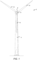
- FIG. 1 illustrates a typical Horizontal Axis Wind Turbine (HAWT) 2 that includes an electrical power generating arrangement, as is shown in Figure 2 .
- HAWT Horizontal Axis Wind Turbine
- this particular image depicts an on-shore wind turbine, it will be understood that equivalent features will also be found on off-shore wind turbines.
- ⁇ horizontal axis' it will be appreciated by the skilled person that for practical purposes, the axis is usually slightly inclined to prevent contact between the rotor blades and the wind turbine tower in the event of strong winds.
- the wind turbine 2 comprises a tower 4, a nacelle 6 rotatably coupled to the top of the tower 4 by a yaw system (not shown), a rotating hub or 'rotor' 8 mounted to the nacelle 4 and a plurality of wind turbine rotor blades 10 coupled to the hub 8.
- the nacelle 4 and rotor blades 10 are turned and directed into the wind direction by the yaw system.
- the nacelle 6 houses an electrical power generating arrangement 20, which includes a powertrain or drivertrain. Both terms are used in the technical art, and 'powertrain' will be used from now on for consistency.
- the wind turbine powertrain comprises a gearbox 22, and a generator 24 which are driven by a main shaft 26.
- the main shaft 26 is supported by a main bearing housing 28 and is connected to, and driven by, the rotor 8 thereby providing input drive to the gearbox 22.
- the gearbox 22 steps up the rotational speed of the low speed main shaft 26 via internal gears (not shown) and drives a gearbox output shaft (not shown in Fig 2 ).
- the gearbox output shaft in turn drives the generator 24, which converts the rotation of the gearbox output shaft into electricity.
- the electricity generated by the generator 24 may then be converted by other components (not shown) as required before being supplied to an appropriate consumer, for example an electrical grid distribution system.
- an epicyclic gearbox comprises a series of planet gears that are arranged about a central sun gear, and which collectively are arranged within an encircling ring gear.
- Such a gearbox may include more than one stage of planet gears.
- the ratio of the number of teeth between the ring gear, the planet gear and the sun gears may be used to determine the gear ratio of the gearbox.
- fine detail of the gearbox will not be described in further detail here as the gearbox is not the principal subject of the invention. Suffice to say that other gearbox configurations could also be used.
- Figure 3 shows some components more clearly. It should be noted here Figure 3 is schematic in form and so for brevity and clarity some components of the generator are not shown or described so as not to detract from the focus of this discussion.
- the main shaft 26 is supported in the main bearing housing 28 by a front bearing 32 and a rear bearing 34.
- the axially-spaced bearings 32,34 ensure that the main shaft 26 is supported securely to rotate about the main rotational axis, shown here as R, despite the high loads that are imposed upon it.
- the gearbox 22 is an epicyclic gearbox, the main shaft 26, the gearbox 22 and the generator 24 are all centred on and share the same rotational axis R.
- the main shaft 26 is coupled to the gearbox 22 at a gearbox input shaft 36.
- the gearbox 22 is coupled to the generator 24 by a gearbox output shaft 38.
- the gearbox output shaft 38 is coupled to a rotor 40 of the generator 24, hereinafter ⁇ generator rotor'.
- the generator 24 in the arrangement shown it is an IPM (interior permanent magnet) electric machine having an external stator 50 which surrounds the generator rotor 40.
- IPM internal permanent magnet
- the generator stator 50 is in a radially outer position relative to the generator rotor 40 and surrounds it as compared to generator designs in which the rotor is external to the stator.
- the magnetically active components of the generator 24 are contained within a generator housing 53 which in this arrangement is cuboidal in form, as can be seen in Figure 2 .
- an elongate hollow conduit or shaft in the form of a "pitch tube” 60 is provided in order to transfer hydraulic and electrical services from the stationary frame of the nacelle to the rotating frame of the main rotor hub.
- the pitch tube 60 extends along the rotational axis R and passes through the generator 24, the gearbox 22 and extends into the main shaft 26.
- the precise form of the pitch tube is not crucial to the invention and so further explanation is omitted.
- pitch tube 60 extends through different components of the powertrain, suitable seals are necessary to ensure that ambient environments of the powertrain are not contaminated by oil-filled environments. For instance, the internal environment of the generator needs to be protected from oil and grease inside the gearbox. However, the sealing demands can be challenging to satisfy because it can be difficult to ensure that the pitch tube is truly concentric with the gearbox output shaft. In circumstances where the pitch tube is slightly misaligned, the effectiveness of conventional rotational seals may be compromised which can lead to admittance of oil mist into the generator and increased wear on the running surface of the pitch tube.
- the pitch tube 60 has an outside diameter that is smaller than the internal diameter of the gearbox output shaft 38 so that an annular volume 74 is defined between these two components. It is this annular volume 74 that must be sealed in order to prevent contamination between the oil-laden environment inside the gearbox 22 and the ambient environment of the generator 24.
- the seal arrangement 70 is located in the annular volume 74 between the pitch tube 60 and the gearbox output shaft 38. More specifically, in this embodiment the seal arrangement 70 is located in the annular volume 74 in a position proximate to the opening 76 of the internal bore 72 of the gearbox output shaft 38.
- a seal member such as an annular lip seal would be mounted on the gearbox output shaft 38 and seal against a running surface of the pitch tube 60.
- a conventional arrangement would be vulnerable to concentricity errors between the two shafts which could lead to excessive wear on the running surface of the pitch tube and/or increased leakage from the seal.
- the seal arrangement 70 of the invention is mounted, supported or otherwise affixed to the pitch tube 60. More specifically, the sealing arrangement 70 is rotatably mounted to the pitch tube 60 so that it is able to rotate relative to it. As can be seen in the Figures, the sealing arrangement 70 is mounted directly to the pitch tube 60 in that there are no other shafts or housing components between them. The sealing arrangement 70 is therefore fixed to the pitch tube 60 in such a way that it is able to rotate whilst fixed to the pitch tube. Expressed another way, the pitch tube 60 carries the sealing arrangement 70.
- the seal arrangement 70 includes two components; a bearing 82 and a seal member 84.
- the bearing 82 is shown here as a roller bearing as this is a convenient way to provide a low friction interface between the pitch tube 60 and the seal member 84.
- other types of bearings would be acceptable, for example different types of ball bearings, roller bearings and friction bearings.
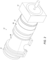
- Figure 4 shows a side view of the seal member 84
- Figure 5 shows a perspective view in which detail may be better appreciated.
- the seal member 84 in this embodiment is an annular component which is generally cylindrical in outer form.
- the interior form of the seal member 84 is shaped to define two sections: a first section 86 serves a connecting function to connect or fix the seal member 84 to the bearing 82; whilst a second section 88 serves the sealing function.
- the two sections 86,88 each define approximately half of the axial length of the seal member 84.
- the first section 86 of the seal member 84 includes a circular socket 90 defined by a cylindrical inner wall 92, the inner diameter of which is comparable to that of the outer diameter of the bearing 82 on which it is mounted.
- the socket 90 has a frustoconical base or floor 94 at which point the first section 86 merges into the second section 88.
- the second section 88 therefore has thicker wall section compared to the first section 86.
- the seal member 84 may be mounted on the bearing 82 by way of a press fit since the internal diameter of the socket 90 is comparable to the outer diameter of the bearing 82. Additional or alternative measures may be taken to ensure a secure fixing. For example, a suitable bonding agent may be applied to the contact surfaces of one or both of these components. Furthermore, a suitable circlip, set screw or pin arrangement may be integrated into the seal arrangement 70 to ensure that the seal member 84 is connected securely to the bearing 82. It is also envisaged that heat shrinking may be a suitable option for securing the seal member onto the bearing.
- the second section 88 of the seal member 84 provides the sealing function.
- the second section 88 defines a labyrinth seal 98.
- the labyrinth seal 98 is depicted as a simple non-isolating radial labyrinth seal featuring a plurality of axially-spaced annular sealing fins 100 that are defined by the second section 88 of the seal member.
- the seal member 84 is configured such that the sealing fins 100 define a very small gap with the underlying running surface of the pitch tube 60 to provide a non-contact seal.
- Drain channels 101 are provided in the seal member 84 so that the fluid captured between the fins 100 can be expelled radially outwards.
- Other types of labyrinth seals would also be acceptable in this application, such as axial labyrinth seals and isolating labyrinth seals.
- the pitch tube could be provided with counter fins that extend radially in a direction away from the pitch tube and interdigitated with the fins of the sealing member.
- other seal types such as lip seals could be used.
- Combinations of seal types may also be used. The skilled person would understand, however, that different types of seal may increase the complexity of the arrangement.
- the seal member 80 may be made from any suitable material. Different materials may be more suited to different applications. For example, types of engineering plastics and rubbers (e.g. nylon, PEEK, FKM or EPDM) may be suitable for some applications, as would metal seals (e.g. steel).
- types of engineering plastics and rubbers e.g. nylon, PEEK, FKM or EPDM
- metal seals e.g. steel
- the seal arrangement 70 is rotatably mounted on the pitch tube 60, the sealing fins 100 of the seal member 84 are accurately positioned with respect to the opposed running surface irrespective of how accurately the pitch tube 60 is mounted with respect to the gearbox output shaft 38. This ensures an accurate seal is established.
- the outer diameter of the seal arrangement 70 is less than the internal diameter of the gearbox output shaft 38. This ensures that the seal arrangement 70 is able to run freely within the annular volume 74 and also provides space to accommodate eccentric mounting between the pitch tube 60 and the gearbox output shaft 38. Due to the difference in diameters, an annular gap 102 is defined between the radially outer surface 103 of the pitch tube 60 and the internal bore 72. Expressed another way, the seal member 84 is spaced from the internal bore 72. It will be noted that any eccentricity in how the pitch tube 60 is mounted with respect to the gearbox output shaft 38 will cause the annular gap 102 to be non-uniform around its circumference. In effect, therefore, it may be considered that any tolerance between the pitch tube 60 and the gearbox output shaft 38 is transferred radially outwards to the annular gap 102 between the seal arrangement 70 and the gearbox output shaft 38.
- the seal arrangement 70 includes a cover in the form of a flexible annular seal 104 that closes the annular gap 102.
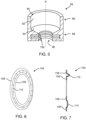
- the flexible annular seal 104 is also shown in Figure 6 in perspective view.
- the flexible annular seal 104 is in the form of a ring or membrane seal.
- the ring seal 104 is shaped so as to be generally planar in cross section. When installed in the annular gap 102, the plane of the ring seal 104 is transverse to the rotational axis R.
- the planar shape of the ring seal 104 together with the material from which it is made, provides it with radial resilience so that it is able to stretch in the radial direction in order to accommodate non-uniformity in the annular gap 102.
- a flat ring would be acceptable for the ring seal 104
- the illustrated embodiment is shaped to provide a greater degree of flexibility.
- the ring seal 104 comprises radially inner and outer flanges or lips 106, 108 which are connected by an intermediate ridge, rib or bridge 110.
- the curved shape of the bridge 110 links the inner and outer flanges 106,108 out of the general plane of the ring seal 104 and therefore provides a greater degree of flexibility to allow the inner and outer flanges 106,108 to move towards and away from each other.
- Figure 7 depicts the ring seal 104 adapting to a non-uniform annular gap 102 in which the lower part of the ring seal 104, in the orientation shown in the diagram, is stretched relative to the upper part, wherein the majority of the stretch is accommodated by the bridge 110.
- the two radial flanges 106,108 of the ring seal may be secured to their respective mounting surfaces in any suitable way. Although not shown here, it is envisaged that the flanges 106, 108 could be adhesively bonded or mechanically fastened to the surfaces to which they are required to be attached.
- the ring seal 104 is positioned so that it extends between a surface of the gearbox output shaft 38 and a surface of the sealing arrangement 70 and, as such, closes the annular gap 102. More specifically, in the illustrated embodiment, the ring seal 104 extends between respective adjacent axial-facing surfaces 112, 114 of the gearbox output shaft 38 and the sealing arrangement 102. The adjacent axial-facing surfaces 112, 114 are aligned in the axial direction along the rotational axis R.
- the ring seal 104 may be attached to the associated mounting surfaces by any suitable means, including clamping rings and bolts, as is appropriate and as would be apparent to the skilled person.
- the ring seal 104 serves as a radial linkage between the seal member 84 and the gearbox output shaft 38. Since the seal member 84 is mounted on the bearing 82, the ring seal 104 acts as a torque rest and as such makes seal member 84 rotate in synchronisation with the gearbox output shaft 38. Since the gearbox output shaft 38 rotates at a higher speed than the pitch tube 60, this helps to ensure the labyrinth seal operates optimally as such seals tend to be more effective at capturing leaking fluids due to the higher radial forces.
- the seal arrangement 70 is relatively compact in the axial direction along the rotational axis R. This means that the sealing function of the seal member 84 is predictable and reliable and does not take up excessive space in the annular volume 74 between the two shafts 38.60.
- the second portion 88 of the seal member 84 is positioned close to the bearing, as shown by the dimension D1 on Figure 4 . More specifically, dimension D1 is less than the radial distance of the annular volume 74 between the gearbox output shaft 38 and the pitch tube 60, which is indicated on Figure 4 as dimension D2. The dimension D1 is also less than the diameter of the pitch tube 60, which is indicated as dimension D3.
- the depth of the seal member 84 that is the axial length of the seal member 84 when oriented as shown in Figure 4 , as indicated by the dimension D4 is substantially equal to that of the dimension D2.
- the bearing (82) is accommodated within the axial length of the seal member 84 and, in this embodiment, does not protrude from the socket 92. This contributes to the space-efficient package of the seal arrangement 70.
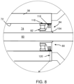
- the seal arrangement 70 is configured to be mounted directly to the pitch tube 60 and also to seal against a running surface on the pitch tube 60. Expressed in another way, the seal arrangement 70 provides a radially inward facing seal. However, it is envisaged that the principles of the invention apply also to a seal arrangement that may be configured to provide a radially outer seal between two rotating shafts. Such a configuration is depicted in Figure 8 , in which it will be noted the components are common with the previous Figures, and so the same reference numerals will be used for clarity. A detailed description of this arrangement will not be provided and only the differences will be explained.
- the seal arrangement 70 is located in the same position as in Figure 4 , namely in the annular volume 74 between the pitch tube 60 and the generator output shaft 38 at an axial position adjacent to the open end of the gearbox output shaft 38.
- the orientation of the seal arrangement 70 has been inverted so that the bearing 82 is fixed to the internal bore 72 of the gearbox output shaft 38 and the seal member 84 is opposed to and so seals against a running surface on the gearbox output shaft 38. It follows, therefore, that the annular gap 102 that is closed by the ring seal 104 is now defined by the radially inward surface of the seal arrangement 70 and the outer surface of the pitch tube 60.
- an optional set of counter fins 116 mounted on a carrier 118.
- the counter fins 116 oppose the fins of the labyrinth sealing member 84 and thus provide additional isolation for the seal arrangement 70. More specifically, the counter fines 116 are interdigitated with the fins of the sealing member 84 as would be understood by the skilled person.
- the counter fins 116 and associated carrier 118 may form an annular component that could be received over the sealing member 84 and the bearing 82. The combined assembly of the counter fins 116/carrier 118, the sealing member 84 and the bearing 82 could therefore be installed as a single component.
- a suitable drain channel 120 could be provided in the outer shaft 38 in order to drain leakage fluid from the seal arrangement 70 through to a suitable drain or sump.
- the seal arrangement 70 is located in the space between nested rotating shafts, such that the radially outer shaft 38 in effect is a rotating housing for the inner shaft/pitch tube 60.
- the invention may also be advantageous in applications where the radially inner shaft extends through a stationary housing.
Landscapes
- Engineering & Computer Science (AREA)
- General Engineering & Computer Science (AREA)
- Mechanical Engineering (AREA)
- Life Sciences & Earth Sciences (AREA)
- Sustainable Development (AREA)
- Sustainable Energy (AREA)
- Chemical & Material Sciences (AREA)
- Combustion & Propulsion (AREA)
- Sealing Using Fluids, Sealing Without Contact, And Removal Of Oil (AREA)
Claims (15)
- Einrichtung, umfassend:eine erste Welle (38) und eine zweite Welle (60), die in einer im Wesentlichen konzentrischen Beziehung gelagert sind, sodass sie imstande sind, sich in Bezug zueinander um eine Rotationsachse (R) zu rotieren; wobei eine der ersten und zweiten Welle (38, 60) durch eine Bohrung (72) hindurch verläuft, die in der anderen von der ersten und zweiten Welle (38, 60) definiert ist;eine Dichtungsanordnung (70) zwischen der ersten und der zweiten Welle (38, 60), wobei die Dichtungsanordnung (70) ein Dichtungselement (84) und ein Lager (82) umfasst, wobei das Dichtungselement (84) für eine Rotationsbewegung in Bezug zur ersten Welle (38) gesperrt ist;wobei die Dichtungsanordnung (70) einen ersten Abschnitt (86) umfasst, der durch das Lager (82) rotierbar auf der zweiten Welle (60) montiert ist, und einen zweiten Abschnitt (88), der konfiguriert ist, um gegen eine Lauffläche, die durch die zweite Welle (60) definiert ist, abzudichten.
- Einrichtung nach Anspruch 1, wobei die Dichtungsanordnung (70) eine radiale Oberfläche (103) umfasst, die der ersten Welle (38) gegenüberliegt, wodurch ein ringförmiger Spalt (102) definiert wird.
- Einrichtung nach Anspruch 2, wobei die Dichtungsanordnung (70) eine flexible ringförmige Dichtung (104) beinhaltet, die den ringförmigen Spalt (102) schließt.
- Einrichtung nach Anspruch 3, wobei sich die flexible ringförmige Dichtung (104) zwischen einer Oberfläche (112) der ersten Welle (38) und einer Oberfläche (114) der Dichtungsanordnung (70) erstreckt, um den ringförmigen Spalt (102) zu schließen.
- Einrichtung nach Anspruch 3 oder 4, wobei sich die flexible ringförmige Dichtung (104) zwischen jeweiligen benachbarten, axial zugewandten Oberflächen der ersten Welle und der Dichtungsanordnung erstreckt.
- Einrichtung nach einem der Ansprüche 3 bis 5, wobei die flexible ringförmige Dichtung (104) eine Membrandichtung ist.
- Einrichtung nach einem der vorstehenden Ansprüche, wobei das Lager (82), auf dem der erste Abschnitt (86) der Dichtungsanordnung (70) an der ersten zweiten Welle (60) montiert ist, ein Wälzlager ist.
- Einrichtung nach einem der vorstehenden Ansprüche, wobei der zweite Abschnitt der Dichtungsanordnung (70) eine oder mehrere Lippendichtungen beinhaltet.
- Einrichtung nach einem der vorstehenden Ansprüche, wobei der zweite Abschnitt der Dichtungsanordnung (70) eine Labyrinthdichtung beinhaltet.
- Einrichtung nach einem der vorstehenden Ansprüche, wobei die erste Welle (38) eine radial äußere Welle ist, durch die hindurch die zweite Welle (60) verläuft.
- Einrichtung nach einem der vorstehenden Ansprüche, wobei der erste Abschnitt (86) und der zweite Abschnitt (88) durch ein Dichtungselement (84) definiert sind.
- Einrichtung nach einem der vorstehenden Ansprüche, wobei die erste Welle (38) rotierbar ist und wobei die zweite Welle (60) rotierbar ist.
- Einrichtung nach einem der vorstehenden Ansprüche, wobei der zweite Abschnitt (88) der Dichtungsanordnung (70) von dem Lager (82) durch einen axialen Abstand (D1) entlang der Rotationsachse (R) getrennt ist, der kleiner ist als ein radialer Abstand (D2) eines ringförmigen Volumens (74), das zwischen der ersten Welle (38) und der zweiten Welle (60) definiert ist.
- Einrichtung nach einem der vorstehenden Ansprüche, wobei die axiale Länge (D4) der Dichtungsanordnung (70), entlang der Rotationsachse (R) angenommen, im Wesentlichen gleich einem radialen Abstand (D2) eines ringförmigen Volumens (74) ist, das zwischen der ersten Welle (38) und der zweiten Welle (60) definiert ist.
- Einrichtung, umfassend:ein Gehäuse (38), das eine Innenbohrung (72) definiert;eine Welle (60), die sich durch die Innenbohrung (72) hindurch erstreckt und die rotierbar in Bezug auf das Gehäuse (38) montiert ist, um um eine Rotationsachse (R) herum zu rotieren;eine Dichtungsanordnung (70) zwischen der Innenbohrung (72) des Gehäuses (38) und der Welle (60), wobei die Dichtungsanordnung (70) ein Dichtungselement (84) und ein Lager (82) umfasst, das Dichtungselement (84) für eine Rotationsbewegung in Bezug zum Gehäuse (38) gesperrt ist; wobei die Dichtungsanordnung (70) ein Dichtungselement (84) umfasst, das von der Innenbohrung (72) des Gehäuses (38) beabstandet ist und einen ersten Abschnitt (86) beinhaltet, der durch das Lager (82) rotierbar auf der Welle gelagert ist, und einen zweiten Abschnitt (88), der konfiguriert ist, um gegen eine durch die Welle (60) definierte Lauffläche abzudichten.
Applications Claiming Priority (2)
| Application Number | Priority Date | Filing Date | Title |
|---|---|---|---|
| DKPA201970675 | 2019-10-31 | ||
| PCT/DK2020/050269 WO2021083466A1 (en) | 2019-10-31 | 2020-10-02 | Apparatus for sealing rotatable components of a wind turbine powertrain |
Publications (3)
| Publication Number | Publication Date |
|---|---|
| EP4051899A1 EP4051899A1 (de) | 2022-09-07 |
| EP4051899C0 EP4051899C0 (de) | 2024-12-04 |
| EP4051899B1 true EP4051899B1 (de) | 2024-12-04 |
Family
ID=72840280
Family Applications (1)
| Application Number | Title | Priority Date | Filing Date |
|---|---|---|---|
| EP20789830.5A Active EP4051899B1 (de) | 2019-10-31 | 2020-10-02 | Vorrichtung zum abdichten von drehbaren bauteilen eines windturbinenantriebsstrangs |
Country Status (5)
| Country | Link |
|---|---|
| US (1) | US11767823B2 (de) |
| EP (1) | EP4051899B1 (de) |
| CN (1) | CN114585811B (de) |
| ES (1) | ES2997238T3 (de) |
| WO (1) | WO2021083466A1 (de) |
Families Citing this family (5)
| Publication number | Priority date | Publication date | Assignee | Title |
|---|---|---|---|---|
| DE102021201875B4 (de) * | 2021-02-26 | 2023-06-07 | Flender Gmbh | Getriebe bzw. Verfahren zum Betrieb eines Getriebes |
| WO2023001347A1 (en) * | 2021-07-20 | 2023-01-26 | Vestas Wind Systems A/S | Powertrain assembly for a wind turbine |
| EP4345299A1 (de) * | 2022-09-27 | 2024-04-03 | Flender GmbH | Betriebssichere lageranordnung für ein pitchrohr einer windkraftanlage |
| DE102023207306A1 (de) | 2023-07-31 | 2025-02-06 | Zf Wind Power Antwerpen N.V. | Anordnung zum Abdichten eines Pitchrohrs |
| EP4621215A1 (de) * | 2024-03-18 | 2025-09-24 | Flender GmbH | Pitchrohr zur durchleitung von versorgungsleitungen einer blatteinstellwinkelregelung für eine windkraftanlage |
Citations (5)
| Publication number | Priority date | Publication date | Assignee | Title |
|---|---|---|---|---|
| US4972986A (en) * | 1988-11-01 | 1990-11-27 | Eg&G Sealol, Inc. | Circumferential inter-seal for sealing between relatively rotatable concentric shafts |
| US20040026867A1 (en) * | 2002-08-09 | 2004-02-12 | Adams David J. | Bearing seal |
| US20160003302A1 (en) * | 2014-07-01 | 2016-01-07 | Uchiyama Manufacturing Corp. | Sealing device |
| EP3168462A1 (de) * | 2015-11-11 | 2017-05-17 | Nordex Energy GmbH | Vorrichtung zur lagerung eines leitungsrohrs in einer rotorwelle einer windenergieanlage, rotorwelle und windenergieanlage |
| KR20190108287A (ko) * | 2018-03-14 | 2019-09-24 | 씰링크 주식회사 | 직선 및 회전운동 밀폐장치 |
Family Cites Families (8)
| Publication number | Priority date | Publication date | Assignee | Title |
|---|---|---|---|---|
| BE486955A (de) * | 1948-01-23 | |||
| DE102007060890A1 (de) | 2007-12-14 | 2009-06-18 | Rolls-Royce Deutschland Ltd & Co Kg | Abdichtung mindestens einer Welle mit mindestens einer hydraulischen Dichtung |
| EP2080904B8 (de) | 2008-01-17 | 2011-06-22 | Gamesa Innovation & Technology, S.L. | Getriebeeinheit für eine Windturbine |
| US7815536B2 (en) | 2009-01-16 | 2010-10-19 | General Electric Company | Compact geared drive train |
| FR2989116B1 (fr) * | 2012-04-05 | 2014-04-25 | Snecma | Dispositif d'etancheite inter-arbres coaxiaux d'une turbomachine |
| US9770981B2 (en) * | 2013-10-18 | 2017-09-26 | General Electric Company | System and method for unified torque transmission and rotary sealing |
| DE102014200674A1 (de) | 2014-01-16 | 2015-07-16 | Zf Friedrichshafen Ag | Anschlussstück für ein Pitchrohr |
| CN105317733A (zh) * | 2014-07-02 | 2016-02-10 | 重庆美的通用制冷设备有限公司 | 旋转密封装置及具有它的压缩机 |
-
2020
- 2020-10-02 ES ES20789830T patent/ES2997238T3/es active Active
- 2020-10-02 EP EP20789830.5A patent/EP4051899B1/de active Active
- 2020-10-02 US US17/641,969 patent/US11767823B2/en active Active
- 2020-10-02 WO PCT/DK2020/050269 patent/WO2021083466A1/en not_active Ceased
- 2020-10-02 CN CN202080073392.8A patent/CN114585811B/zh active Active
Patent Citations (5)
| Publication number | Priority date | Publication date | Assignee | Title |
|---|---|---|---|---|
| US4972986A (en) * | 1988-11-01 | 1990-11-27 | Eg&G Sealol, Inc. | Circumferential inter-seal for sealing between relatively rotatable concentric shafts |
| US20040026867A1 (en) * | 2002-08-09 | 2004-02-12 | Adams David J. | Bearing seal |
| US20160003302A1 (en) * | 2014-07-01 | 2016-01-07 | Uchiyama Manufacturing Corp. | Sealing device |
| EP3168462A1 (de) * | 2015-11-11 | 2017-05-17 | Nordex Energy GmbH | Vorrichtung zur lagerung eines leitungsrohrs in einer rotorwelle einer windenergieanlage, rotorwelle und windenergieanlage |
| KR20190108287A (ko) * | 2018-03-14 | 2019-09-24 | 씰링크 주식회사 | 직선 및 회전운동 밀폐장치 |
Also Published As
| Publication number | Publication date |
|---|---|
| US11767823B2 (en) | 2023-09-26 |
| EP4051899C0 (de) | 2024-12-04 |
| US20220307481A1 (en) | 2022-09-29 |
| CN114585811B (zh) | 2025-05-02 |
| ES2997238T3 (en) | 2025-02-14 |
| WO2021083466A1 (en) | 2021-05-06 |
| EP4051899A1 (de) | 2022-09-07 |
| CN114585811A (zh) | 2022-06-03 |
Similar Documents
| Publication | Publication Date | Title |
|---|---|---|
| EP4051899B1 (de) | Vorrichtung zum abdichten von drehbaren bauteilen eines windturbinenantriebsstrangs | |
| CN100540889C (zh) | 具有一体形成的转子轴承的风轮机齿轮机构 | |
| EP2172665A1 (de) | Trägerstruktur und windkraftgenerator | |
| US20110138963A1 (en) | Active sealing-draining device | |
| EP2078888A1 (de) | Dichtung zur Verwendung in einem Schmiersystem | |
| EP2260207B1 (de) | Eine lagerdichtung umfassende windturbine | |
| US20120141270A1 (en) | Drivetrain and method for lubricating bearing in wind turbine | |
| US10047850B2 (en) | Slew drive with torque tube | |
| US11473565B2 (en) | Fluid film bearing and wind turbine | |
| CN101631975A (zh) | 润滑介质密封装置和带有润滑介质密封装置的风力涡轮机 | |
| CN114483497A (zh) | 用于风力涡轮动力传动系统的球形轴颈轴承 | |
| US20140084588A1 (en) | Gas bearing supported turbomachine with reduction gear assembly | |
| CN109681616B (zh) | 齿轮箱滑环密封结构 | |
| CN104246146A (zh) | 用于涡轮机械同轴的轴之间密封的设备 | |
| DK2677171T3 (en) | Wind turbine with a coupling means located between the planetary gear and the generator for equalizing axial, radial and angular displacement | |
| CN118110787A (zh) | 用于风力涡轮机的发电机转子的轴向密封件 | |
| CN204267738U (zh) | 旋转气密轴系及使用该轴系的转动密封舱装置 | |
| US20260104033A1 (en) | Transmission arrangement and wind turbine | |
| CN216612818U (zh) | 一种电动滚筒 | |
| JP7042176B2 (ja) | 発電機の回転翼支持構造 | |
| CN103998772B (zh) | 风力发电装置及其建设方法 | |
| WO2024140181A1 (zh) | 传动系统及风力发电机组 | |
| JP4523672B1 (ja) | 変速機 | |
| JP2016148429A (ja) | 摩擦ローラ式変速機 | |
| CN103998772A (zh) | 风力发电装置及其建设方法 |
Legal Events
| Date | Code | Title | Description |
|---|---|---|---|
| STAA | Information on the status of an ep patent application or granted ep patent |
Free format text: STATUS: UNKNOWN |
|
| STAA | Information on the status of an ep patent application or granted ep patent |
Free format text: STATUS: THE INTERNATIONAL PUBLICATION HAS BEEN MADE |
|
| PUAI | Public reference made under article 153(3) epc to a published international application that has entered the european phase |
Free format text: ORIGINAL CODE: 0009012 |
|
| STAA | Information on the status of an ep patent application or granted ep patent |
Free format text: STATUS: REQUEST FOR EXAMINATION WAS MADE |
|
| 17P | Request for examination filed |
Effective date: 20220517 |
|
| AK | Designated contracting states |
Kind code of ref document: A1 Designated state(s): AL AT BE BG CH CY CZ DE DK EE ES FI FR GB GR HR HU IE IS IT LI LT LU LV MC MK MT NL NO PL PT RO RS SE SI SK SM TR |
|
| DAV | Request for validation of the european patent (deleted) | ||
| DAX | Request for extension of the european patent (deleted) | ||
| STAA | Information on the status of an ep patent application or granted ep patent |
Free format text: STATUS: EXAMINATION IS IN PROGRESS |
|
| 17Q | First examination report despatched |
Effective date: 20240403 |
|
| GRAP | Despatch of communication of intention to grant a patent |
Free format text: ORIGINAL CODE: EPIDOSNIGR1 |
|
| STAA | Information on the status of an ep patent application or granted ep patent |
Free format text: STATUS: GRANT OF PATENT IS INTENDED |
|
| INTG | Intention to grant announced |
Effective date: 20240605 |
|
| GRAS | Grant fee paid |
Free format text: ORIGINAL CODE: EPIDOSNIGR3 |
|
| GRAA | (expected) grant |
Free format text: ORIGINAL CODE: 0009210 |
|
| STAA | Information on the status of an ep patent application or granted ep patent |
Free format text: STATUS: THE PATENT HAS BEEN GRANTED |
|
| AK | Designated contracting states |
Kind code of ref document: B1 Designated state(s): AL AT BE BG CH CY CZ DE DK EE ES FI FR GB GR HR HU IE IS IT LI LT LU LV MC MK MT NL NO PL PT RO RS SE SI SK SM TR |
|
| REG | Reference to a national code |
Ref country code: CH Ref legal event code: EP |
|
| REG | Reference to a national code |
Ref country code: DE Ref legal event code: R096 Ref document number: 602020042593 Country of ref document: DE |
|
| REG | Reference to a national code |
Ref country code: IE Ref legal event code: FG4D |
|
| U01 | Request for unitary effect filed |
Effective date: 20241218 |
|
| U07 | Unitary effect registered |
Designated state(s): AT BE BG DE DK EE FI FR IT LT LU LV MT NL PT RO SE SI Effective date: 20250110 |
|
| REG | Reference to a national code |
Ref country code: ES Ref legal event code: FG2A Ref document number: 2997238 Country of ref document: ES Kind code of ref document: T3 Effective date: 20250214 |
|
| PG25 | Lapsed in a contracting state [announced via postgrant information from national office to epo] |
Ref country code: HR Free format text: LAPSE BECAUSE OF FAILURE TO SUBMIT A TRANSLATION OF THE DESCRIPTION OR TO PAY THE FEE WITHIN THE PRESCRIBED TIME-LIMIT Effective date: 20241204 |
|
| PG25 | Lapsed in a contracting state [announced via postgrant information from national office to epo] |
Ref country code: NO Free format text: LAPSE BECAUSE OF FAILURE TO SUBMIT A TRANSLATION OF THE DESCRIPTION OR TO PAY THE FEE WITHIN THE PRESCRIBED TIME-LIMIT Effective date: 20250304 |
|
| PG25 | Lapsed in a contracting state [announced via postgrant information from national office to epo] |
Ref country code: GR Free format text: LAPSE BECAUSE OF FAILURE TO SUBMIT A TRANSLATION OF THE DESCRIPTION OR TO PAY THE FEE WITHIN THE PRESCRIBED TIME-LIMIT Effective date: 20250305 |
|
| PG25 | Lapsed in a contracting state [announced via postgrant information from national office to epo] |
Ref country code: RS Free format text: LAPSE BECAUSE OF FAILURE TO SUBMIT A TRANSLATION OF THE DESCRIPTION OR TO PAY THE FEE WITHIN THE PRESCRIBED TIME-LIMIT Effective date: 20250304 |
|
| PG25 | Lapsed in a contracting state [announced via postgrant information from national office to epo] |
Ref country code: SM Free format text: LAPSE BECAUSE OF FAILURE TO SUBMIT A TRANSLATION OF THE DESCRIPTION OR TO PAY THE FEE WITHIN THE PRESCRIBED TIME-LIMIT Effective date: 20241204 |
|
| PG25 | Lapsed in a contracting state [announced via postgrant information from national office to epo] |
Ref country code: PL Free format text: LAPSE BECAUSE OF FAILURE TO SUBMIT A TRANSLATION OF THE DESCRIPTION OR TO PAY THE FEE WITHIN THE PRESCRIBED TIME-LIMIT Effective date: 20241204 |
|
| PG25 | Lapsed in a contracting state [announced via postgrant information from national office to epo] |
Ref country code: IS Free format text: LAPSE BECAUSE OF FAILURE TO SUBMIT A TRANSLATION OF THE DESCRIPTION OR TO PAY THE FEE WITHIN THE PRESCRIBED TIME-LIMIT Effective date: 20250404 |
|
| PG25 | Lapsed in a contracting state [announced via postgrant information from national office to epo] |
Ref country code: SK Free format text: LAPSE BECAUSE OF FAILURE TO SUBMIT A TRANSLATION OF THE DESCRIPTION OR TO PAY THE FEE WITHIN THE PRESCRIBED TIME-LIMIT Effective date: 20241204 |
|
| PG25 | Lapsed in a contracting state [announced via postgrant information from national office to epo] |
Ref country code: CZ Free format text: LAPSE BECAUSE OF FAILURE TO SUBMIT A TRANSLATION OF THE DESCRIPTION OR TO PAY THE FEE WITHIN THE PRESCRIBED TIME-LIMIT Effective date: 20241204 |
|
| PLBE | No opposition filed within time limit |
Free format text: ORIGINAL CODE: 0009261 |
|
| STAA | Information on the status of an ep patent application or granted ep patent |
Free format text: STATUS: NO OPPOSITION FILED WITHIN TIME LIMIT |
|
| 26N | No opposition filed |
Effective date: 20250905 |
|
| U20 | Renewal fee for the european patent with unitary effect paid |
Year of fee payment: 6 Effective date: 20251027 |
|
| PGFP | Annual fee paid to national office [announced via postgrant information from national office to epo] |
Ref country code: GB Payment date: 20251023 Year of fee payment: 6 |
|
| PGFP | Annual fee paid to national office [announced via postgrant information from national office to epo] |
Ref country code: ES Payment date: 20251118 Year of fee payment: 6 |