EP4051932B1 - Vanne rotative ayant un temps de rinçage réduit - Google Patents
Vanne rotative ayant un temps de rinçage réduit Download PDFInfo
- Publication number
- EP4051932B1 EP4051932B1 EP20780403.0A EP20780403A EP4051932B1 EP 4051932 B1 EP4051932 B1 EP 4051932B1 EP 20780403 A EP20780403 A EP 20780403A EP 4051932 B1 EP4051932 B1 EP 4051932B1
- Authority
- EP
- European Patent Office
- Prior art keywords
- channel
- rotor
- stator
- rotary valve
- rotation axis
- Prior art date
- Legal status (The legal status is an assumption and is not a legal conclusion. Google has not performed a legal analysis and makes no representation as to the accuracy of the status listed.)
- Active
Links
Images
Classifications
-
- F—MECHANICAL ENGINEERING; LIGHTING; HEATING; WEAPONS; BLASTING
- F16—ENGINEERING ELEMENTS AND UNITS; GENERAL MEASURES FOR PRODUCING AND MAINTAINING EFFECTIVE FUNCTIONING OF MACHINES OR INSTALLATIONS; THERMAL INSULATION IN GENERAL
- F16K—VALVES; TAPS; COCKS; ACTUATING-FLOATS; DEVICES FOR VENTING OR AERATING
- F16K11/00—Multiple-way valves, e.g. mixing valves; Pipe fittings incorporating such valves
- F16K11/02—Multiple-way valves, e.g. mixing valves; Pipe fittings incorporating such valves with all movable sealing faces moving as one unit
- F16K11/06—Multiple-way valves, e.g. mixing valves; Pipe fittings incorporating such valves with all movable sealing faces moving as one unit comprising only sliding valves, i.e. sliding closure elements
- F16K11/072—Multiple-way valves, e.g. mixing valves; Pipe fittings incorporating such valves with all movable sealing faces moving as one unit comprising only sliding valves, i.e. sliding closure elements with pivoted closure members
- F16K11/074—Multiple-way valves, e.g. mixing valves; Pipe fittings incorporating such valves with all movable sealing faces moving as one unit comprising only sliding valves, i.e. sliding closure elements with pivoted closure members with flat sealing faces
- F16K11/0743—Multiple-way valves, e.g. mixing valves; Pipe fittings incorporating such valves with all movable sealing faces moving as one unit comprising only sliding valves, i.e. sliding closure elements with pivoted closure members with flat sealing faces with both the supply and the discharge passages being on one side of the closure plates
-
- G—PHYSICS
- G01—MEASURING; TESTING
- G01N—INVESTIGATING OR ANALYSING MATERIALS BY DETERMINING THEIR CHEMICAL OR PHYSICAL PROPERTIES
- G01N30/00—Investigating or analysing materials by separation into components using adsorption, absorption or similar phenomena or using ion-exchange, e.g. chromatography or field flow fractionation
- G01N30/02—Column chromatography
- G01N30/04—Preparation or injection of sample to be analysed
- G01N30/16—Injection
- G01N30/20—Injection using a sampling valve
- G01N2030/202—Injection using a sampling valve rotary valves
Definitions
- the invention relates to a rotary valve.
- Rotary valves may be used in laboratory automation systems for distributing liquids, such as reagents, dilutions, samples, etc.
- a rotary valve usually comprises a stator member with stator channels and a rotor member, which comprises a rotor channel. Dependent on different rotary positions, the rotor channel interconnects different stator channels with each other.
- a pump may convey a liquid from a first container and/or channel into the rotary valve and the rotary valve may distribute the liquid into other containers and/or channels dependent on its rotor position.
- the rotary valve also may draw from one of a plurality of source containers and may distribute the fluid into a common outlet.
- a fast flushing time of the valve may increase the overall throughput of an analytical instrument.
- a second important feature of any valve in a laboratory automation system is the flushing volume, i.e. the volume required to substitute a first liquid in the valve with another liquid. the first liquid has to be flushed out completely by the other liquid in order to prevent cross contamination which may impact downstream processes/analyses.
- Small flushing volume may decrease flushing time and/or may save precious reagents.
- US 7 308 908 B2 shows a rotary valve with a stator channel in a stator member, which stator channel is transversely aligned to a rotation axis of a rotor member.
- US 2016 0 033 049 A1 shows a multi-path selector valve with planar rotor and stator faces, in which rotor channels and stator channels are provided that are interconnected in a specific rotor position.
- US 5 419 208 A shows a multiport selection valve with curved rotor and stator faces.
- the openings of the rotor and stator channels, which can be aligned with each other, have walls, which are orthogonal to the respective part of the corresponding face.
- the objective of the invention is a rotary valve with a reduced flushing time.
- the invention relates to a rotary valve comprising a stator member with a planar stator face, the stator member having a plurality of stator channels for conducting a fluid and a rotor member with a planar rotor face facing and in contact with the stator face, the rotor member having at least one rotor channel.
- the rotor member is rotatable with respect to the stator member about a rotation axis, such that in a conduction position, the rotor channel interconnects two of the stator channels and the two stator channels are in fluid communication.
- the stator face and the rotor face may be parallel.
- the rotation axis may be aligned orthogonally to the stator face and the rotor face.
- the stator member and the rotor member may be accommodated in a housing of the rotary valve, wherein the stator member may be statically connected with the housing and the rotor member may be rotatably connected with the housing.
- the rotor member may be rotated by a step motor.
- a pump such as an automatically actuated syringe, may be connected to one of the stator channels.
- the housing of the rotary valve furthermore may comprise means for pressing the rotor face against the stator face, such as a spring.
- the stator member and/or the rotor member may be made of a ceramics material e.g. alumina, metal e.g. stainless steel or polymer e.g. PEEK (Polyetheretherketone) or ETFE (Ethylene Tetrafluoroethylene).
- the stator channels may be made of bores machined in the material before or after sintering or formed by inserting a wire before pressing or molding, which are removed after forming.
- the rotor channel may be made by machining a groove into the material. It also may be that the rotor member and/or the stator member are 3D printed, for example by laser sintering.
- stator member has a stator channel with a central opening that opens into the rotor channel in any conduction position. It may be that the stator member has one or more eccentric stator channels with an opening spaced apart from the rotation axis. In a specific conduction position, one of the eccentric stator channels may be connected with the stator channel with the central opening.
- At least one of the stator channels has a transverse channel section opening into the stator face and running transversely with respect to the stator face, the rotor face and/or the rotation axis.
- Transverse may mean that a central line of the transfers channel is not orthogonal with respect to the stator face and/or the rotor face.
- Transverse may mean that a central line of the transverse channel projected onto a plane comprising the rotation axis is not parallel and is not orthogonal.
- the transverse channel section may have a cylindrical form and/or may have a circular cross-section. It also may be that the transverse channel section has an ellipsoid, egg shaped or polygonal cross-section.
- the interface of the transverse channel section and the stator face may be elongated, such as egg-shaped or ellipsoidal.
- the overall length of the fluid path through the stator member and the rotor member may be shortened. This may decrease the flushing time.
- the flushing performance may be improved compared to an orthogonal orientation.
- the at least one stator channel with the transverse channel section may be an eccentric stator channel.
- the stator member has more than one eccentric stator channel
- each of the eccentric stator channels may have a transverse channel section. At least some of the transverse channel sections may be symmetric with respect to each other by rotation about the rotation axis.
- stator channels there is one or more pairs of stator channels, which are interconnected by a rotor channel. Both stator channels of a pair may have transverse channel sections. It also may be that one stator channel of a pair has a transverse channel section and that the other one is orthogonally aligned to the stator face.
- the pairs of stator channels may be symmetric with respect to each other by rotation about the rotation axis.
- the rotor channel has a bottom, which at an intersection end of the rotor channel is inclined with respect to the rotor face, the stator face and the rotation axis, such that the rotor channel elongates an inner surface of the stator channel, when the rotor member is in the conducting position.
- inclined means that the bottom has a substantially flat bottom surface and substantially straight bottom line, which is angled with respect to the rotor face, the stator face and/or the rotation axis.
- turbulences and/or vorticities in the transition between the rotor channel and the stator channel may be reduced. This also may reduce the flushing time, since a more laminar fluid flow may be achieved. Furthermore, a reduced flushing volume may be achieved by avoiding dead points.
- An inclined bottom of the rotor channel may be provided by a rotor channel, which at the intersection end becomes deeper with increasing distance from the outermost position of the rotor channel. Over a range, the increase of the depth may be linear with respect to the distance to the outermost position.
- the rotor channel is a groove in the rotor face. Over its complete extension, the rotor channel is always opened towards the rotor face.
- the rotor channel has a U-shaped cross-section.
- the bottom surface of the rotor channel may have a substantial circular cross-section.
- a bottom line of the rotor channel at the intersection end is inclined with respect to the rotor face, the stator face and/or the rotation axis.
- the bottom line may be composed of the lowest points of the U-shaped cross-sections along the extension of the rotor channel.
- the bottom of the rotor channel at the interconnection end is inclined with respect to the rotor face, the stator face and the rotation axis with the same angle as the stator channel.
- a cylindrical shape of the transverse channel section of the stator channel may be elongated substantially flush with the rotor channel.
- the rotor channel extends radially with respect to the rotation axis.
- the rotor channel may be substantially straight.
- One end of the rotor channel may be at the center of the rotor member, i.e. at the rotation axis.
- the rotor channel extends tangential with respect to a circle around the rotation axis. It also may be that there are a plurality of rotor channels, which may be distributed symmetrically with respect to the rotation axis.
- a center line of the transverse channel section intersects with the rotation axis.
- the rotation axis and the stator channel may be arranged in one plane.
- the stator member comprises a parallel stator channel, which runs parallel to and/or along the rotation axis of the rotor member.
- the parallel stator channel may be the only input and/or output of the rotary valve from which the fluid is distributed to and/or collected from the eccentric stator channels, which then act as outputs and/or inputs. Both sections may have a circular cross-section and/or may be centred with respect to each other.
- a parallel stator channel is running spaced apart from the rotation axis.
- pairs of stator channels, which are arranged symmetrically around the rotation axis may have a parallel stator channel.
- a connection port may be a substantially cylindrical opening in the rotary valve for connecting pipes or hoses to the rotary valve.
- the connection ports which may be designed to receive screwed fittings, may be provided by the stator member or a further member of the rotary valve arranged on a surface of the stator member opposite to the stator face.
- the parallel stator channel has a first section opening into the rotor channel and a second section opening towards a connection port of the rotary valve.
- the second section has a smaller diameter as the first section. This may help forming a laminar fluid flow between the connection port and the parallel stator channel and/or also may reduce the flushing time.
- the stator member comprises a circular groove surrounding the stator face.
- the circular groove may have an inclined surface, which is inclined with respect to the rotation axis.
- the transverse channel section(s) of the one or more eccentric stator channels may run along this circular groove.
- the transverse channel sections open the possibility, such that such a groove can be formed in the stator.
- the stator With the groove, the stator may be designed more compact.
- the circular groove also may provide space so that any leakage between the rotor member and stator member may leave the rotary valve through a drain hole, rather than forcing through the sealed bearing and possibly damaging the bearing and/or valve.
- the inclined surface is inclined with respect to the rotation axis with the same angle as the transverse channel section. In such a way, material between the inclined surface and the transverse channel sections may be spared.
- a bearing surrounding the rotor member protrudes into the circular groove.
- the bearing may be used for supporting a rotation of the rotor.
- An overall length of the rotary valve may be reduced.
- the bearing may be a sliding bearing or a ball bearing.
- the stator channel with the transverse channel section has a parallel channel section, which opens towards a connection port of the rotary valve.
- the parallel channel section runs parallel to the rotation axis.
- the transverse channel section and the parallel channel section may have the same diameter and/or may have a circular cross-section.
- the connection port to the stator channel may be aligned parallel to the rotation axis. In such a way, a laminar fluid flow between the stator channel and the connection port is supported. This also may support reducing the flushing time.
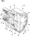
- Fig. 1 shows a rotary valve 10 with a rotor assembly 12 and a stator assembly 14 in a housing 16.
- the rotor assembly 12 comprises a spring element 18, a bearing 20 (such as a ball baearing), a sleeve 22, a rotor member 24 and a sliding bearing 26.
- the spring element 18, which lies on an annular ground wall 28 of the housing 16, presses the rotor member 24 via the bearing 20 and the sleeve 22 against the stator assembly 14.
- a sealing ring 30 tights the rotor assembly against the housing 16.
- the rotor member 24 is rotatably mounted to the bearing 20 and rotatable mounted inside the sliding bearing 26.
- the rotor member 24 is adapted to rotate about a rotation axis A.
- a shaft of a gear and/or an electrical motor may be mounted into the sleeve 22 and into an opening 32 of the rotor member 24.
- the stator assembly 14 comprises a stator member 36, which is fixed to the housing 16.
- a bolt 38 prevents a rotation of the stator member 36.
- a port member 40 of the stator assembly 14 is arranged on the stator member 36 and fixed into the housing with a screw ring 42.
- the port member 40 comprises connection ports 44 for connecting lines or hoses to the rotary valve 10.
- the connection ports 44 are substantially cylindrical openings extending parallel to the rotation axis.
- the stator member 36 comprises stator channels 46, 48 (see also Fig. 2 ), which enter into the connection ports 44.
- the rotor member 24 comprises a rotor channel 50, which in specific rotor positions interconnects the parallel stator channel 46 and one of the eccentric stator channels 48. In such a rotor position, a fluid can flow from the central port 44 to one of the other ports 44 or vice versa. In other positions, the fluid flow may be blocked.
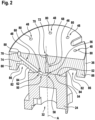
- Fig. 2 shows the rotor member 24 and the stator member 36 in more detail.
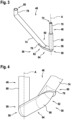
- Fig. 3 and 4 show the inner surfaces of a stator channel 48 and the rotor channel 50.
- the rotor member 24 has a planar, disk shaped rotor face 52 in which the rotor channel 50 is provided as a groove.
- the stator member 36 has a planar, disk shaped stator face 54, which faces and is in contact with the rotor face 52.
- the spring element 18 presses the rotor face 52 against the stator face 54, such that a fluid tight connection is generated.
- FIG. 2 the rotor member 24 and the stator member 36 are shown in a conducting position, in which a fluid flow through the rotary valve is possible.
- the parallel stator channel 46 has a circular opening 56 in the stator face 54 and is positioned over a central extension end 58 of the rotor channel 50.
- An eccentric stator channel 48 has an irregular, elongated opening 60 in the stator face 54 and is positioned over an eccentric extension end 62 of the rotor channel.
- the rotor channel 50 extends from the extension end 58 to the extension end 62 in a radial direction with respect to the rotation axis A.
- the extension end 58 has a semi-circular border.
- the extension end 62 has an ellipsoidal border. In between the extension ends, the borders of the rotor channel 50 are parallel.
- the rotor channel 50 has a U-shaped cross-section with respect to planes orthogonal to the radial direction and the rotation axis A.
- the rotor channel 50 has a longitudinal section, which, starting from the extension end 62, is inclined with respect to the rotation axis A, after that runs in radial direction and at the extension end 58 has a 90° turn into a line parallel to the rotation axis A.
- the complete bottom 64 of the rotor channel 50 is inclined with respect to the rotation axis A and/or with the bottom 64 of the rotor channel 50 between the extension ends 62, 58.
- a substantially straight bottom line 66 is inclined in this way.
- the bottom 64 and/or the bottom line 66 runs orthogonal to the rotation axis A.
- the bottom and/or the bottom line goes over into a line parallel to the rotation axis A.
- the bottom 64 of the rotor channel 50 at the interconnection end 58 is aligned orthogonally to the rotation axis A.
- the parallel stator channel 46 has a first section 68, which opens into the rotor channel 50 at the opening 56, and a second section 70, which opens towards a connection port 44 of the rotary valve 10 at a further circular opening 72. Both sections 68, 70 have a circular cross-section. The second section 70 has a smaller diameter as the first section 68. The opening 72 extends from the diameter of the second section to the diameter of the first section 68.
- Each of the eccentric stator channels 48 has a transverse channel section 74, which opens into the stator face 54 at the respective opening 60.
- the transverse channel section 74 runs transversely with respect to the rotation axis A.
- the transverse channel section 74 has a substantially cylindrical shape with a center line 74 that intersects with the rotation axis A.
- the bottom 64 and/or bottom line 66 of the rotor channel 50 at the interconnection end 62 is inclined with respect to the rotation axis A with the same angle as transverse channel section 74 and/or its center line.
- the rotor channel 50 and its bottom 64 at the intersection end 62 are formed, such that the rotor channel 50 elongates an inner surface of the transverse channel section 74.
- the opening 60 of the transverse channel section 74 has a side wall 76 running parallel to the rotation axis A at a side, where an angle between the transverse channel section 74 and the stator face 54 is acute.
- the opening 60 may be egg-shaped, i.e. may have a border, which is partially ellipsoidal shaped and partially circular shaped.
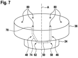
- Each of the eccentric stator channels 48 have a parallel channel section 78, which opens towards one of the connection ports 44 with an opening 80.
- the channel section 78 as well as the opening 80 have a circular cross-section and the same diameter as the transverse channel section 74.
- An angle between the transverse channel section 74 and the parallel channel section 78 is obtuse.
- the parallel channel section 78 runs parallel to the rotation axis A.
- the stator member 36 comprises a circular groove 82 surrounding the stator face 54.
- the circular groove 82 has an inclined surface 84, which is inclined with respect to the rotation axis A with the same angle as the transverse channel sections 74 of the eccentric stator channels 48.
- the bearing 26 surrounding the rotor member 24 protrudes into the circular groove 82.
- the circular groove 82 has a cylindrical surface 86. In such a way, a rim 88 is generated, which mechanically stabilizes the stator member 36.
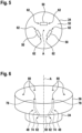
- Fig. 5 shows that the rotor member 24 may comprise more than one rotor channel 50.
- a plurality of rotor channels 50 are arranged rotational symmetric to the rotation axis A.
- Each of these rotor channels 50 may interconnect two stator channels 46, 48 as shown in the following drawings.
- the stator member 36 comprises two eccentric stator channels 48, which are interconnectable by a rotor channel 50 as shown in Fig. 5 .
- the eccentric stator channels 48 may be formed as shown in Fig. 2-4 .
- the rotor channel 50 may have intersection ends 62, such as shown in Fig. 2-4 .
- the stator member 36 comprises an eccentric stator channels 48 and a parallel stator channel 46, which are interconnectable by a rotor channel 50 as shown in Fig. 5 .
- the eccentric stator channel 48 may be formed as shown in Fig. 2-4 .
- the eccentric stator channel 48 also may be formed, such as shown in Fig. 2-4 , however, may be spaced apart from the rotation axis A.
- the rotor channel 50 may have one eccentric intersection end 62, such as shown in Fig. 2-4 .
- the other end of the rotor channel 50 may be formed like the central intersection end 58 as shown in Fig. 2-4 , however may be spaced apart from the rotation axis A.
Landscapes
- Engineering & Computer Science (AREA)
- General Engineering & Computer Science (AREA)
- Mechanical Engineering (AREA)
- Multiple-Way Valves (AREA)
Claims (11)
- Vanne rotative (10), comprenant :un élément formant stator (36) avec une face de stator plane, l'élément formant stator (36) présentant une pluralité de canaux de stator (46, 48) pour conduire un fluide ;un élément formant rotor (24) avec une face de rotor plane (52) faisant face et en contact avec la face de stator, l'élément formant rotor (24) présentant un canal de rotor (50) ;dans laquelle l'élément formant rotor (24) est rotatif par rapport à l'élément formant stator (36) autour d'un axe de rotation (A), de sorte que, dans une position conductrice, le canal de rotor (50) relie deux des canaux de stator (46, 48) et les deux canaux de stator (46, 48) sont en communication fluidique ;dans laquelle au moins l'un des canaux de stator (48) a une section de canal transversale (74) s'ouvrant dans la face de stator (54) et s'étendant transversalement par rapport à la face de stator (54) ;dans laquelle le canal de rotor (50) a un fond (64) qui, à une extrémité d'intersection (62) du canal de rotor (50), est incliné par rapport à la face de rotor (52), de sorte que le canal de rotor (50) prolonge une surface intérieure du canal de stator (48) lorsque l'élément formant rotor (24) est dans la position conductrice ;dans laquelle le canal de rotor (50) est une rainure dans la face de rotor (52) et le canal de rotor est toujours ouvert vers la face de rotor sur toute son extension ;caractérisée en ce que le fond (64) du canal de rotor (50) à l'extrémité d'interconnexion (62) est incliné par rapport à la face du rotor (52) et à l'axe de rotation (A) du même angle que le canal de stator (48), de sorte qu'une forme cylindrique de la section de canal transversale (74) du canal de stator (48) est allongée en affleurement avec le canal de rotor (50).
- Vanne rotative (10) selon la revendication 1,
dans laquelle le canal de rotor (50) a une section transversale en forme de U. - Vanne rotative (10) selon l'une des revendications précédentes,
dans laquelle le fond (64) du canal de rotor (50), à une deuxième extrémité d'interconnexion (58) qui s'ouvre dans un autre canal de stator (46), est aligné orthogonalement à l'axe de rotation (A). - Vanne rotative (10) selon l'une des revendications précédentes,dans laquelle le canal de rotor (50) s'étend radialement par rapport à l'axe de rotation (A) ; oudans laquelle le canal de rotor (50) s'étend tangentiellement par rapport à un cercle autour de l'axe de rotation (A).
- Vanne rotative (10) selon l'une des revendications précédentes,
dans laquelle une ligne centrale de la section de canal transversale (74) coupe l'axe de rotation (A). - Vanne rotative (10) selon l'une des revendications précédentes,
dans laquelle l'élément formant stator (36) comprend un canal de stator parallèle (46) qui s'étend parallèlement à l'axe de rotation (A) de l'élément formant rotor (24). - Vanne rotative (10) selon la revendication 6,dans laquelle le canal de stator parallèle (46) a une première section (68) qui s'ouvre dans le canal de rotor (50) et une deuxième section (70) qui s'ouvre vers un orifice de connexion (44) de la vanne rotative (10) ;dans laquelle la deuxième section (70) a un diamètre plus petit que la première section (68).
- Vanne rotative (10) selon l'une des revendications précédentes,
dans laquelle l'élément formant stator (36) comprend une rainure circulaire (82) entourant la face de stator (54) ; dans laquelle la rainure circulaire (82) présente une surface inclinée (84) qui est inclinée par rapport à l'axe de rotation (A) . - Vanne rotative selon la revendication 8,
dans laquelle la surface inclinée (84) est inclinée par rapport à l'axe de rotation (A) du même angle que la section de canal transversale (74). - Vanne rotative (10) selon les revendications 8 ou 9,
dans laquelle un palier (26) entourant l'élément formant rotor (24) fait saillie dans la rainure circulaire (82). - Vanne rotative (10) selon l'une des revendications précédentes,dans laquelle le canal de stator (48) avec la section de canal transversale (74) a une section de canal parallèle (78) qui s'ouvre vers un orifice de connexion (44) de la vanne rotative (10) ;dans laquelle la section de canal parallèle (78) s'étend parallèlement à l'axe de rotation (A).
Applications Claiming Priority (1)
| Application Number | Priority Date | Filing Date | Title |
|---|---|---|---|
| PCT/US2020/049448 WO2022050956A1 (fr) | 2020-09-04 | 2020-09-04 | Vanne rotative ayant un temps de rinçage réduit |
Publications (2)
| Publication Number | Publication Date |
|---|---|
| EP4051932A1 EP4051932A1 (fr) | 2022-09-07 |
| EP4051932B1 true EP4051932B1 (fr) | 2023-11-08 |
Family
ID=72644879
Family Applications (1)
| Application Number | Title | Priority Date | Filing Date |
|---|---|---|---|
| EP20780403.0A Active EP4051932B1 (fr) | 2020-09-04 | 2020-09-04 | Vanne rotative ayant un temps de rinçage réduit |
Country Status (4)
| Country | Link |
|---|---|
| US (1) | US12038091B2 (fr) |
| EP (1) | EP4051932B1 (fr) |
| CN (1) | CN114930059B (fr) |
| WO (1) | WO2022050956A1 (fr) |
Families Citing this family (3)
| Publication number | Priority date | Publication date | Assignee | Title |
|---|---|---|---|---|
| CN114930059B (zh) * | 2020-09-04 | 2025-11-25 | 帝肯贸易股份公司 | 具有减少的冲洗时间的旋转阀 |
| US12320441B1 (en) * | 2021-02-08 | 2025-06-03 | Schivo Medical Limited | Centering electronic rotary valve |
| US12297931B2 (en) | 2021-02-08 | 2025-05-13 | Schivo Medical Limited | Centering electronic rotary valve |
Family Cites Families (21)
| Publication number | Priority date | Publication date | Assignee | Title |
|---|---|---|---|---|
| AT206706B (de) * | 1957-06-19 | 1959-12-28 | Escher Wyss Ag | Rohrverzweigungsstück mit Verstärkungsrippe |
| US4450613A (en) * | 1982-01-21 | 1984-05-29 | Wfi International, Inc. | Method of manufacturing acute angled vessel connector |
| US5419208A (en) | 1993-01-29 | 1995-05-30 | Upchurch Scientific, Inc. | Multiport selection valve |
| JP3400903B2 (ja) * | 1995-09-26 | 2003-04-28 | ダイワ精工株式会社 | 中通し釣竿 |
| JP2002267083A (ja) * | 2001-03-06 | 2002-09-18 | Kawasaki Steel Corp | 配管分岐部の接合構造 |
| DE112004002159B4 (de) * | 2003-11-10 | 2021-04-22 | Waters Technologies Corp. (N.D.Ges.D. Staates Delaware) | Vorrichtung und Verfahren zum Steuern des Flusses von Fluid in einer Leitung |
| US20090320925A1 (en) * | 2008-06-25 | 2009-12-31 | Rheodyne, Llc | Rotor element for a shear valve with subterranean passage and method |
| US8261773B2 (en) | 2009-07-30 | 2012-09-11 | Idex Health & Science Llc | Multi-position micro-fluidic valve system with removable encoder assembly |
| DE102012021818A1 (de) * | 2011-12-08 | 2013-06-13 | Heidelberger Druckmaschinen Ag | Drehverbindung zwischen zwei relativ um eine Achse beweglichen Bauteilen |
| GB201207365D0 (en) * | 2012-04-27 | 2012-06-13 | Ge Healthcare Bio Sciences Ab | Improvements in and relating to rotary selection valves |
| KR101380472B1 (ko) * | 2012-05-04 | 2014-04-01 | 전북대학교산학협력단 | 내구성이 보강된 유체촉매방식 분해유닛 |
| WO2014047108A1 (fr) | 2012-09-20 | 2014-03-27 | Waters Technologies Corporation | Valve sélectrice rotative et systèmes et procédés associés |
| DE202012104261U1 (de) * | 2012-11-06 | 2014-02-07 | Richard Weinhold | Rohrkupplungsvorrichtung |
| CN203477720U (zh) * | 2013-10-13 | 2014-03-12 | 上海新闵(东台)重型锻造有限公司 | 电站用大口径厚壁三通 |
| RU2688746C2 (ru) | 2014-06-05 | 2019-05-22 | Иллумина, Инк. | Системы и способы с использованием поворотного клапана для по меньшей мере одного из приготовления образца или анализа образца |
| US9739383B2 (en) * | 2014-07-29 | 2017-08-22 | Idex Health & Science Llc | Multi-path selector valve |
| CN204717195U (zh) * | 2015-06-03 | 2015-10-21 | 上海新闵(东台)重型锻造有限公司 | 超临界机组主蒸汽管道斜三通 |
| CN107121519A (zh) * | 2016-02-24 | 2017-09-01 | 北京历元仪器有限公司 | 一种内置流通通道结构的切换阀 |
| JP7094199B2 (ja) * | 2018-10-26 | 2022-07-01 | Toyo Tire株式会社 | 防振ブッシュ |
| US20200200720A1 (en) * | 2018-12-20 | 2020-06-25 | Waters Technologies Corporation | Optical detector flow cell for co2-based chromatography |
| CN114930059B (zh) * | 2020-09-04 | 2025-11-25 | 帝肯贸易股份公司 | 具有减少的冲洗时间的旋转阀 |
-
2020
- 2020-09-04 CN CN202080089585.2A patent/CN114930059B/zh active Active
- 2020-09-04 WO PCT/US2020/049448 patent/WO2022050956A1/fr not_active Ceased
- 2020-09-04 US US17/756,099 patent/US12038091B2/en active Active
- 2020-09-04 EP EP20780403.0A patent/EP4051932B1/fr active Active
Also Published As
| Publication number | Publication date |
|---|---|
| CN114930059B (zh) | 2025-11-25 |
| WO2022050956A1 (fr) | 2022-03-10 |
| US12038091B2 (en) | 2024-07-16 |
| EP4051932A1 (fr) | 2022-09-07 |
| CN114930059A (zh) | 2022-08-19 |
| US20220403943A1 (en) | 2022-12-22 |
Similar Documents
| Publication | Publication Date | Title |
|---|---|---|
| EP4051932B1 (fr) | Vanne rotative ayant un temps de rinçage réduit | |
| CN101617226B (zh) | 用于试样注入的转动阀 | |
| CA2387226C (fr) | Robinet a tournant dote de segments d'etancheite avec ressorts d'appoint | |
| KR19990024027A (ko) | 조절가능한 누출방지 체결시스템 | |
| JP6758660B2 (ja) | 回転バルブおよびクロマトグラフィシステム | |
| JP6636468B2 (ja) | ポンプのための圧力緩和回転子組立体 | |
| SG183479A1 (en) | Ball valve | |
| CN100419314C (zh) | 球阀组件 | |
| US8403656B2 (en) | Vane pump consisting of a two-part stator | |
| CN106102913B (zh) | 旋转式取样阀以及装备有此类阀的装置 | |
| CA2580387C (fr) | Pompe volumetrique rotative comprenant un grattoir et guide du grattoir | |
| KR100236027B1 (ko) | 사판 펌프 | |
| US20260079133A1 (en) | Injection valve | |
| EP2442001A2 (fr) | Soupape d'arrêt | |
| WO2021075184A1 (fr) | Vanne de commutation de chemin d'écoulement, système de vanne de commutation de chemin d'écoulement et chromatographe en phase liquide | |
| JP5388187B2 (ja) | 一軸偏心ねじポンプ | |
| JP7150248B2 (ja) | 水栓装置及びその製造方法 | |
| CN116379183A (zh) | 旋转阀及色谱分析系统和蛋白纯化系统 | |
| FR2848281A1 (fr) | Robinet a boisseau | |
| KR100944387B1 (ko) | 원통형 밸브 | |
| KR200195734Y1 (ko) | 유동방향 변환장치 | |
| CN216843246U (zh) | 转动阀及具有该转动阀的层析实验系统 | |
| EP2759747B1 (fr) | Soupape de liquide | |
| EP4467854A1 (fr) | Procédé d'assemblage pour soupape de commutation de trajet d'écoulement | |
| KR20040006452A (ko) | 자흡식 펌프용 개량 임펠러 및 그 조립 구조체와 이를포함하는 자흡식 펌프 |
Legal Events
| Date | Code | Title | Description |
|---|---|---|---|
| STAA | Information on the status of an ep patent application or granted ep patent |
Free format text: STATUS: UNKNOWN |
|
| STAA | Information on the status of an ep patent application or granted ep patent |
Free format text: STATUS: THE INTERNATIONAL PUBLICATION HAS BEEN MADE |
|
| PUAI | Public reference made under article 153(3) epc to a published international application that has entered the european phase |
Free format text: ORIGINAL CODE: 0009012 |
|
| STAA | Information on the status of an ep patent application or granted ep patent |
Free format text: STATUS: REQUEST FOR EXAMINATION WAS MADE |
|
| 17P | Request for examination filed |
Effective date: 20220602 |
|
| AK | Designated contracting states |
Kind code of ref document: A1 Designated state(s): AL AT BE BG CH CY CZ DE DK EE ES FI FR GB GR HR HU IE IS IT LI LT LU LV MC MK MT NL NO PL PT RO RS SE SI SK SM TR |
|
| STAA | Information on the status of an ep patent application or granted ep patent |
Free format text: STATUS: EXAMINATION IS IN PROGRESS |
|
| 17Q | First examination report despatched |
Effective date: 20220907 |
|
| GRAP | Despatch of communication of intention to grant a patent |
Free format text: ORIGINAL CODE: EPIDOSNIGR1 |
|
| STAA | Information on the status of an ep patent application or granted ep patent |
Free format text: STATUS: GRANT OF PATENT IS INTENDED |
|
| INTG | Intention to grant announced |
Effective date: 20230414 |
|
| GRAS | Grant fee paid |
Free format text: ORIGINAL CODE: EPIDOSNIGR3 |
|
| GRAA | (expected) grant |
Free format text: ORIGINAL CODE: 0009210 |
|
| STAA | Information on the status of an ep patent application or granted ep patent |
Free format text: STATUS: THE PATENT HAS BEEN GRANTED |
|
| AK | Designated contracting states |
Kind code of ref document: B1 Designated state(s): AL AT BE BG CH CY CZ DE DK EE ES FI FR GB GR HR HU IE IS IT LI LT LU LV MC MK MT NL NO PL PT RO RS SE SI SK SM TR |
|
| DAV | Request for validation of the european patent (deleted) | ||
| DAX | Request for extension of the european patent (deleted) | ||
| REG | Reference to a national code |
Ref country code: GB Ref legal event code: FG4D |
|
| REG | Reference to a national code |
Ref country code: CH Ref legal event code: EP |
|
| REG | Reference to a national code |
Ref country code: DE Ref legal event code: R096 Ref document number: 602020020788 Country of ref document: DE |
|
| REG | Reference to a national code |
Ref country code: IE Ref legal event code: FG4D |
|
| P01 | Opt-out of the competence of the unified patent court (upc) registered |
Effective date: 20231219 |
|
| REG | Reference to a national code |
Ref country code: LT Ref legal event code: MG9D |
|
| REG | Reference to a national code |
Ref country code: NL Ref legal event code: MP Effective date: 20231108 |
|
| PG25 | Lapsed in a contracting state [announced via postgrant information from national office to epo] |
Ref country code: GR Free format text: LAPSE BECAUSE OF FAILURE TO SUBMIT A TRANSLATION OF THE DESCRIPTION OR TO PAY THE FEE WITHIN THE PRESCRIBED TIME-LIMIT Effective date: 20240209 |
|
| PG25 | Lapsed in a contracting state [announced via postgrant information from national office to epo] |
Ref country code: IS Free format text: LAPSE BECAUSE OF FAILURE TO SUBMIT A TRANSLATION OF THE DESCRIPTION OR TO PAY THE FEE WITHIN THE PRESCRIBED TIME-LIMIT Effective date: 20240308 |
|
| PG25 | Lapsed in a contracting state [announced via postgrant information from national office to epo] |
Ref country code: LT Free format text: LAPSE BECAUSE OF FAILURE TO SUBMIT A TRANSLATION OF THE DESCRIPTION OR TO PAY THE FEE WITHIN THE PRESCRIBED TIME-LIMIT Effective date: 20231108 |
|
| REG | Reference to a national code |
Ref country code: AT Ref legal event code: MK05 Ref document number: 1629874 Country of ref document: AT Kind code of ref document: T Effective date: 20231108 |
|
| PG25 | Lapsed in a contracting state [announced via postgrant information from national office to epo] |
Ref country code: NL Free format text: LAPSE BECAUSE OF FAILURE TO SUBMIT A TRANSLATION OF THE DESCRIPTION OR TO PAY THE FEE WITHIN THE PRESCRIBED TIME-LIMIT Effective date: 20231108 |
|
| PG25 | Lapsed in a contracting state [announced via postgrant information from national office to epo] |
Ref country code: AT Free format text: LAPSE BECAUSE OF FAILURE TO SUBMIT A TRANSLATION OF THE DESCRIPTION OR TO PAY THE FEE WITHIN THE PRESCRIBED TIME-LIMIT Effective date: 20231108 |
|
| PG25 | Lapsed in a contracting state [announced via postgrant information from national office to epo] |
Ref country code: ES Free format text: LAPSE BECAUSE OF FAILURE TO SUBMIT A TRANSLATION OF THE DESCRIPTION OR TO PAY THE FEE WITHIN THE PRESCRIBED TIME-LIMIT Effective date: 20231108 |
|
| PG25 | Lapsed in a contracting state [announced via postgrant information from national office to epo] |
Ref country code: NL Free format text: LAPSE BECAUSE OF FAILURE TO SUBMIT A TRANSLATION OF THE DESCRIPTION OR TO PAY THE FEE WITHIN THE PRESCRIBED TIME-LIMIT Effective date: 20231108 Ref country code: LT Free format text: LAPSE BECAUSE OF FAILURE TO SUBMIT A TRANSLATION OF THE DESCRIPTION OR TO PAY THE FEE WITHIN THE PRESCRIBED TIME-LIMIT Effective date: 20231108 Ref country code: IS Free format text: LAPSE BECAUSE OF FAILURE TO SUBMIT A TRANSLATION OF THE DESCRIPTION OR TO PAY THE FEE WITHIN THE PRESCRIBED TIME-LIMIT Effective date: 20240308 Ref country code: GR Free format text: LAPSE BECAUSE OF FAILURE TO SUBMIT A TRANSLATION OF THE DESCRIPTION OR TO PAY THE FEE WITHIN THE PRESCRIBED TIME-LIMIT Effective date: 20240209 Ref country code: ES Free format text: LAPSE BECAUSE OF FAILURE TO SUBMIT A TRANSLATION OF THE DESCRIPTION OR TO PAY THE FEE WITHIN THE PRESCRIBED TIME-LIMIT Effective date: 20231108 Ref country code: BG Free format text: LAPSE BECAUSE OF FAILURE TO SUBMIT A TRANSLATION OF THE DESCRIPTION OR TO PAY THE FEE WITHIN THE PRESCRIBED TIME-LIMIT Effective date: 20240208 Ref country code: AT Free format text: LAPSE BECAUSE OF FAILURE TO SUBMIT A TRANSLATION OF THE DESCRIPTION OR TO PAY THE FEE WITHIN THE PRESCRIBED TIME-LIMIT Effective date: 20231108 Ref country code: PT Free format text: LAPSE BECAUSE OF FAILURE TO SUBMIT A TRANSLATION OF THE DESCRIPTION OR TO PAY THE FEE WITHIN THE PRESCRIBED TIME-LIMIT Effective date: 20240308 |
|
| PG25 | Lapsed in a contracting state [announced via postgrant information from national office to epo] |
Ref country code: SE Free format text: LAPSE BECAUSE OF FAILURE TO SUBMIT A TRANSLATION OF THE DESCRIPTION OR TO PAY THE FEE WITHIN THE PRESCRIBED TIME-LIMIT Effective date: 20231108 Ref country code: RS Free format text: LAPSE BECAUSE OF FAILURE TO SUBMIT A TRANSLATION OF THE DESCRIPTION OR TO PAY THE FEE WITHIN THE PRESCRIBED TIME-LIMIT Effective date: 20231108 Ref country code: PL Free format text: LAPSE BECAUSE OF FAILURE TO SUBMIT A TRANSLATION OF THE DESCRIPTION OR TO PAY THE FEE WITHIN THE PRESCRIBED TIME-LIMIT Effective date: 20231108 Ref country code: NO Free format text: LAPSE BECAUSE OF FAILURE TO SUBMIT A TRANSLATION OF THE DESCRIPTION OR TO PAY THE FEE WITHIN THE PRESCRIBED TIME-LIMIT Effective date: 20240208 Ref country code: LV Free format text: LAPSE BECAUSE OF FAILURE TO SUBMIT A TRANSLATION OF THE DESCRIPTION OR TO PAY THE FEE WITHIN THE PRESCRIBED TIME-LIMIT Effective date: 20231108 Ref country code: HR Free format text: LAPSE BECAUSE OF FAILURE TO SUBMIT A TRANSLATION OF THE DESCRIPTION OR TO PAY THE FEE WITHIN THE PRESCRIBED TIME-LIMIT Effective date: 20231108 |
|
| PG25 | Lapsed in a contracting state [announced via postgrant information from national office to epo] |
Ref country code: DK Free format text: LAPSE BECAUSE OF FAILURE TO SUBMIT A TRANSLATION OF THE DESCRIPTION OR TO PAY THE FEE WITHIN THE PRESCRIBED TIME-LIMIT Effective date: 20231108 |
|
| PG25 | Lapsed in a contracting state [announced via postgrant information from national office to epo] |
Ref country code: CZ Free format text: LAPSE BECAUSE OF FAILURE TO SUBMIT A TRANSLATION OF THE DESCRIPTION OR TO PAY THE FEE WITHIN THE PRESCRIBED TIME-LIMIT Effective date: 20231108 |
|
| PG25 | Lapsed in a contracting state [announced via postgrant information from national office to epo] |
Ref country code: SK Free format text: LAPSE BECAUSE OF FAILURE TO SUBMIT A TRANSLATION OF THE DESCRIPTION OR TO PAY THE FEE WITHIN THE PRESCRIBED TIME-LIMIT Effective date: 20231108 |
|
| PG25 | Lapsed in a contracting state [announced via postgrant information from national office to epo] |
Ref country code: SM Free format text: LAPSE BECAUSE OF FAILURE TO SUBMIT A TRANSLATION OF THE DESCRIPTION OR TO PAY THE FEE WITHIN THE PRESCRIBED TIME-LIMIT Effective date: 20231108 Ref country code: SK Free format text: LAPSE BECAUSE OF FAILURE TO SUBMIT A TRANSLATION OF THE DESCRIPTION OR TO PAY THE FEE WITHIN THE PRESCRIBED TIME-LIMIT Effective date: 20231108 Ref country code: RO Free format text: LAPSE BECAUSE OF FAILURE TO SUBMIT A TRANSLATION OF THE DESCRIPTION OR TO PAY THE FEE WITHIN THE PRESCRIBED TIME-LIMIT Effective date: 20231108 Ref country code: IT Free format text: LAPSE BECAUSE OF FAILURE TO SUBMIT A TRANSLATION OF THE DESCRIPTION OR TO PAY THE FEE WITHIN THE PRESCRIBED TIME-LIMIT Effective date: 20231108 Ref country code: EE Free format text: LAPSE BECAUSE OF FAILURE TO SUBMIT A TRANSLATION OF THE DESCRIPTION OR TO PAY THE FEE WITHIN THE PRESCRIBED TIME-LIMIT Effective date: 20231108 Ref country code: DK Free format text: LAPSE BECAUSE OF FAILURE TO SUBMIT A TRANSLATION OF THE DESCRIPTION OR TO PAY THE FEE WITHIN THE PRESCRIBED TIME-LIMIT Effective date: 20231108 Ref country code: CZ Free format text: LAPSE BECAUSE OF FAILURE TO SUBMIT A TRANSLATION OF THE DESCRIPTION OR TO PAY THE FEE WITHIN THE PRESCRIBED TIME-LIMIT Effective date: 20231108 |
|
| REG | Reference to a national code |
Ref country code: DE Ref legal event code: R097 Ref document number: 602020020788 Country of ref document: DE |
|
| PLBE | No opposition filed within time limit |
Free format text: ORIGINAL CODE: 0009261 |
|
| STAA | Information on the status of an ep patent application or granted ep patent |
Free format text: STATUS: NO OPPOSITION FILED WITHIN TIME LIMIT |
|
| 26N | No opposition filed |
Effective date: 20240809 |
|
| PG25 | Lapsed in a contracting state [announced via postgrant information from national office to epo] |
Ref country code: SI Free format text: LAPSE BECAUSE OF FAILURE TO SUBMIT A TRANSLATION OF THE DESCRIPTION OR TO PAY THE FEE WITHIN THE PRESCRIBED TIME-LIMIT Effective date: 20231108 |
|
| PG25 | Lapsed in a contracting state [announced via postgrant information from national office to epo] |
Ref country code: SI Free format text: LAPSE BECAUSE OF FAILURE TO SUBMIT A TRANSLATION OF THE DESCRIPTION OR TO PAY THE FEE WITHIN THE PRESCRIBED TIME-LIMIT Effective date: 20231108 |
|
| PG25 | Lapsed in a contracting state [announced via postgrant information from national office to epo] |
Ref country code: MC Free format text: LAPSE BECAUSE OF FAILURE TO SUBMIT A TRANSLATION OF THE DESCRIPTION OR TO PAY THE FEE WITHIN THE PRESCRIBED TIME-LIMIT Effective date: 20231108 |
|
| PG25 | Lapsed in a contracting state [announced via postgrant information from national office to epo] |
Ref country code: LU Free format text: LAPSE BECAUSE OF NON-PAYMENT OF DUE FEES Effective date: 20240904 |
|
| REG | Reference to a national code |
Ref country code: BE Ref legal event code: MM Effective date: 20240930 |
|
| PG25 | Lapsed in a contracting state [announced via postgrant information from national office to epo] |
Ref country code: BE Free format text: LAPSE BECAUSE OF NON-PAYMENT OF DUE FEES Effective date: 20240930 |
|
| PG25 | Lapsed in a contracting state [announced via postgrant information from national office to epo] |
Ref country code: IE Free format text: LAPSE BECAUSE OF NON-PAYMENT OF DUE FEES Effective date: 20240904 |
|
| REG | Reference to a national code |
Ref country code: CH Ref legal event code: U11 Free format text: ST27 STATUS EVENT CODE: U-0-0-U10-U11 (AS PROVIDED BY THE NATIONAL OFFICE) Effective date: 20251001 |
|
| PG25 | Lapsed in a contracting state [announced via postgrant information from national office to epo] |
Ref country code: FI Free format text: LAPSE BECAUSE OF FAILURE TO SUBMIT A TRANSLATION OF THE DESCRIPTION OR TO PAY THE FEE WITHIN THE PRESCRIBED TIME-LIMIT Effective date: 20231108 |
|
| PGFP | Annual fee paid to national office [announced via postgrant information from national office to epo] |
Ref country code: DE Payment date: 20250919 Year of fee payment: 6 |
|
| PGFP | Annual fee paid to national office [announced via postgrant information from national office to epo] |
Ref country code: GB Payment date: 20250923 Year of fee payment: 6 |
|
| PGFP | Annual fee paid to national office [announced via postgrant information from national office to epo] |
Ref country code: FR Payment date: 20250924 Year of fee payment: 6 |
|
| PGFP | Annual fee paid to national office [announced via postgrant information from national office to epo] |
Ref country code: CH Payment date: 20251001 Year of fee payment: 6 |
|
| PG25 | Lapsed in a contracting state [announced via postgrant information from national office to epo] |
Ref country code: CY Free format text: LAPSE BECAUSE OF FAILURE TO SUBMIT A TRANSLATION OF THE DESCRIPTION OR TO PAY THE FEE WITHIN THE PRESCRIBED TIME-LIMIT; INVALID AB INITIO Effective date: 20200904 |
|
| PG25 | Lapsed in a contracting state [announced via postgrant information from national office to epo] |
Ref country code: HU Free format text: LAPSE BECAUSE OF FAILURE TO SUBMIT A TRANSLATION OF THE DESCRIPTION OR TO PAY THE FEE WITHIN THE PRESCRIBED TIME-LIMIT; INVALID AB INITIO Effective date: 20200904 |