EP4051944B1 - Chemise de tuyau améliorée et procédés associés - Google Patents
Chemise de tuyau améliorée et procédés associés Download PDFInfo
- Publication number
- EP4051944B1 EP4051944B1 EP20803236.7A EP20803236A EP4051944B1 EP 4051944 B1 EP4051944 B1 EP 4051944B1 EP 20803236 A EP20803236 A EP 20803236A EP 4051944 B1 EP4051944 B1 EP 4051944B1
- Authority
- EP
- European Patent Office
- Prior art keywords
- pipe
- liner
- barrier layer
- polymer pipe
- inner polymer
- Prior art date
- Legal status (The legal status is an assumption and is not a legal conclusion. Google has not performed a legal analysis and makes no representation as to the accuracy of the status listed.)
- Active
Links
Images




Classifications
-
- F—MECHANICAL ENGINEERING; LIGHTING; HEATING; WEAPONS; BLASTING
- F16—ENGINEERING ELEMENTS AND UNITS; GENERAL MEASURES FOR PRODUCING AND MAINTAINING EFFECTIVE FUNCTIONING OF MACHINES OR INSTALLATIONS; THERMAL INSULATION IN GENERAL
- F16L—PIPES; JOINTS OR FITTINGS FOR PIPES; SUPPORTS FOR PIPES, CABLES OR PROTECTIVE TUBING; MEANS FOR THERMAL INSULATION IN GENERAL
- F16L55/00—Devices or appurtenances for use in, or in connection with, pipes or pipe systems
- F16L55/16—Devices for covering leaks in pipes or hoses, e.g. hose-menders
- F16L55/162—Devices for covering leaks in pipes or hoses, e.g. hose-menders from inside the pipe
- F16L55/165—Devices for covering leaks in pipes or hoses, e.g. hose-menders from inside the pipe a pipe or flexible liner being inserted in the damaged section
- F16L55/1652—Devices for covering leaks in pipes or hoses, e.g. hose-menders from inside the pipe a pipe or flexible liner being inserted in the damaged section the flexible liner being pulled into the damaged section
-
- F—MECHANICAL ENGINEERING; LIGHTING; HEATING; WEAPONS; BLASTING
- F16—ENGINEERING ELEMENTS AND UNITS; GENERAL MEASURES FOR PRODUCING AND MAINTAINING EFFECTIVE FUNCTIONING OF MACHINES OR INSTALLATIONS; THERMAL INSULATION IN GENERAL
- F16L—PIPES; JOINTS OR FITTINGS FOR PIPES; SUPPORTS FOR PIPES, CABLES OR PROTECTIVE TUBING; MEANS FOR THERMAL INSULATION IN GENERAL
- F16L9/00—Rigid pipes
- F16L9/14—Compound tubes, i.e. made of materials not wholly covered by any one of the preceding groups
- F16L9/147—Compound tubes, i.e. made of materials not wholly covered by any one of the preceding groups comprising only layers of metal and plastics with or without reinforcement
-
- B—PERFORMING OPERATIONS; TRANSPORTING
- B29—WORKING OF PLASTICS; WORKING OF SUBSTANCES IN A PLASTIC STATE IN GENERAL
- B29C—SHAPING OR JOINING OF PLASTICS; SHAPING OF MATERIAL IN A PLASTIC STATE, NOT OTHERWISE PROVIDED FOR; AFTER-TREATMENT OF THE SHAPED PRODUCTS, e.g. REPAIRING
- B29C55/00—Shaping by stretching, e.g. drawing through a die; Apparatus therefor
- B29C55/30—Drawing through a die
-
- B—PERFORMING OPERATIONS; TRANSPORTING
- B29—WORKING OF PLASTICS; WORKING OF SUBSTANCES IN A PLASTIC STATE IN GENERAL
- B29C—SHAPING OR JOINING OF PLASTICS; SHAPING OF MATERIAL IN A PLASTIC STATE, NOT OTHERWISE PROVIDED FOR; AFTER-TREATMENT OF THE SHAPED PRODUCTS, e.g. REPAIRING
- B29C63/00—Lining or sheathing, i.e. applying preformed layers or sheathings of plastics; Apparatus therefor
- B29C63/26—Lining or sheathing of internal surfaces
- B29C63/34—Lining or sheathing of internal surfaces using tubular layers or sheathings
-
- B—PERFORMING OPERATIONS; TRANSPORTING
- B29—WORKING OF PLASTICS; WORKING OF SUBSTANCES IN A PLASTIC STATE IN GENERAL
- B29C—SHAPING OR JOINING OF PLASTICS; SHAPING OF MATERIAL IN A PLASTIC STATE, NOT OTHERWISE PROVIDED FOR; AFTER-TREATMENT OF THE SHAPED PRODUCTS, e.g. REPAIRING
- B29C63/00—Lining or sheathing, i.e. applying preformed layers or sheathings of plastics; Apparatus therefor
- B29C63/38—Lining or sheathing, i.e. applying preformed layers or sheathings of plastics; Apparatus therefor by liberation of internal stresses
- B29C63/42—Lining or sheathing, i.e. applying preformed layers or sheathings of plastics; Apparatus therefor by liberation of internal stresses using tubular layers or sheathings
-
- B—PERFORMING OPERATIONS; TRANSPORTING
- B29—WORKING OF PLASTICS; WORKING OF SUBSTANCES IN A PLASTIC STATE IN GENERAL
- B29C—SHAPING OR JOINING OF PLASTICS; SHAPING OF MATERIAL IN A PLASTIC STATE, NOT OTHERWISE PROVIDED FOR; AFTER-TREATMENT OF THE SHAPED PRODUCTS, e.g. REPAIRING
- B29C63/00—Lining or sheathing, i.e. applying preformed layers or sheathings of plastics; Apparatus therefor
- B29C63/38—Lining or sheathing, i.e. applying preformed layers or sheathings of plastics; Apparatus therefor by liberation of internal stresses
- B29C63/46—Lining or sheathing, i.e. applying preformed layers or sheathings of plastics; Apparatus therefor by liberation of internal stresses of internal surfaces
-
- B—PERFORMING OPERATIONS; TRANSPORTING
- B32—LAYERED PRODUCTS
- B32B—LAYERED PRODUCTS, i.e. PRODUCTS BUILT-UP OF STRATA OF FLAT OR NON-FLAT, e.g. CELLULAR OR HONEYCOMB, FORM
- B32B1/00—Layered products having a non-planar shape
- B32B1/08—Tubular products
-
- B—PERFORMING OPERATIONS; TRANSPORTING
- B32—LAYERED PRODUCTS
- B32B—LAYERED PRODUCTS, i.e. PRODUCTS BUILT-UP OF STRATA OF FLAT OR NON-FLAT, e.g. CELLULAR OR HONEYCOMB, FORM
- B32B15/00—Layered products comprising a layer of metal
- B32B15/04—Layered products comprising a layer of metal comprising metal as the main or only constituent of a layer, which is next to another layer of the same or of a different material
- B32B15/08—Layered products comprising a layer of metal comprising metal as the main or only constituent of a layer, which is next to another layer of the same or of a different material of synthetic resin
-
- B—PERFORMING OPERATIONS; TRANSPORTING
- B32—LAYERED PRODUCTS
- B32B—LAYERED PRODUCTS, i.e. PRODUCTS BUILT-UP OF STRATA OF FLAT OR NON-FLAT, e.g. CELLULAR OR HONEYCOMB, FORM
- B32B15/00—Layered products comprising a layer of metal
- B32B15/04—Layered products comprising a layer of metal comprising metal as the main or only constituent of a layer, which is next to another layer of the same or of a different material
- B32B15/08—Layered products comprising a layer of metal comprising metal as the main or only constituent of a layer, which is next to another layer of the same or of a different material of synthetic resin
- B32B15/085—Layered products comprising a layer of metal comprising metal as the main or only constituent of a layer, which is next to another layer of the same or of a different material of synthetic resin comprising polyolefins
-
- B—PERFORMING OPERATIONS; TRANSPORTING
- B32—LAYERED PRODUCTS
- B32B—LAYERED PRODUCTS, i.e. PRODUCTS BUILT-UP OF STRATA OF FLAT OR NON-FLAT, e.g. CELLULAR OR HONEYCOMB, FORM
- B32B15/00—Layered products comprising a layer of metal
- B32B15/18—Layered products comprising a layer of metal comprising iron or steel
-
- B—PERFORMING OPERATIONS; TRANSPORTING
- B32—LAYERED PRODUCTS
- B32B—LAYERED PRODUCTS, i.e. PRODUCTS BUILT-UP OF STRATA OF FLAT OR NON-FLAT, e.g. CELLULAR OR HONEYCOMB, FORM
- B32B15/00—Layered products comprising a layer of metal
- B32B15/20—Layered products comprising a layer of metal comprising aluminium or copper
-
- B—PERFORMING OPERATIONS; TRANSPORTING
- B32—LAYERED PRODUCTS
- B32B—LAYERED PRODUCTS, i.e. PRODUCTS BUILT-UP OF STRATA OF FLAT OR NON-FLAT, e.g. CELLULAR OR HONEYCOMB, FORM
- B32B27/00—Layered products comprising a layer of synthetic resin
- B32B27/06—Layered products comprising a layer of synthetic resin as the main or only constituent of a layer, which is next to another layer of the same or of a different material
- B32B27/08—Layered products comprising a layer of synthetic resin as the main or only constituent of a layer, which is next to another layer of the same or of a different material of synthetic resin
-
- B—PERFORMING OPERATIONS; TRANSPORTING
- B32—LAYERED PRODUCTS
- B32B—LAYERED PRODUCTS, i.e. PRODUCTS BUILT-UP OF STRATA OF FLAT OR NON-FLAT, e.g. CELLULAR OR HONEYCOMB, FORM
- B32B27/00—Layered products comprising a layer of synthetic resin
- B32B27/30—Layered products comprising a layer of synthetic resin comprising vinyl (co)polymers; comprising acrylic (co)polymers
- B32B27/304—Layered products comprising a layer of synthetic resin comprising vinyl (co)polymers; comprising acrylic (co)polymers comprising vinyl halide (co)polymers, e.g. PVC, PVDC, PVF, PVDF
-
- B—PERFORMING OPERATIONS; TRANSPORTING
- B32—LAYERED PRODUCTS
- B32B—LAYERED PRODUCTS, i.e. PRODUCTS BUILT-UP OF STRATA OF FLAT OR NON-FLAT, e.g. CELLULAR OR HONEYCOMB, FORM
- B32B27/00—Layered products comprising a layer of synthetic resin
- B32B27/32—Layered products comprising a layer of synthetic resin comprising polyolefins
-
- B—PERFORMING OPERATIONS; TRANSPORTING
- B32—LAYERED PRODUCTS
- B32B—LAYERED PRODUCTS, i.e. PRODUCTS BUILT-UP OF STRATA OF FLAT OR NON-FLAT, e.g. CELLULAR OR HONEYCOMB, FORM
- B32B27/00—Layered products comprising a layer of synthetic resin
- B32B27/32—Layered products comprising a layer of synthetic resin comprising polyolefins
- B32B27/322—Layered products comprising a layer of synthetic resin comprising polyolefins comprising halogenated polyolefins, e.g. PTFE
-
- B—PERFORMING OPERATIONS; TRANSPORTING
- B32—LAYERED PRODUCTS
- B32B—LAYERED PRODUCTS, i.e. PRODUCTS BUILT-UP OF STRATA OF FLAT OR NON-FLAT, e.g. CELLULAR OR HONEYCOMB, FORM
- B32B7/00—Layered products characterised by the relation between layers; Layered products characterised by the relative orientation of features between layers, or by the relative values of a measurable parameter between layers, i.e. products comprising layers having different physical, chemical or physicochemical properties; Layered products characterised by the interconnection of layers
- B32B7/04—Interconnection of layers
- B32B7/12—Interconnection of layers using interposed adhesives or interposed materials with bonding properties
-
- F—MECHANICAL ENGINEERING; LIGHTING; HEATING; WEAPONS; BLASTING
- F16—ENGINEERING ELEMENTS AND UNITS; GENERAL MEASURES FOR PRODUCING AND MAINTAINING EFFECTIVE FUNCTIONING OF MACHINES OR INSTALLATIONS; THERMAL INSULATION IN GENERAL
- F16L—PIPES; JOINTS OR FITTINGS FOR PIPES; SUPPORTS FOR PIPES, CABLES OR PROTECTIVE TUBING; MEANS FOR THERMAL INSULATION IN GENERAL
- F16L11/00—Hoses, i.e. flexible pipes
- F16L11/04—Hoses, i.e. flexible pipes made of rubber or flexible plastics
- F16L11/045—Hoses, i.e. flexible pipes made of rubber or flexible plastics with four or more layers without reinforcement
-
- F—MECHANICAL ENGINEERING; LIGHTING; HEATING; WEAPONS; BLASTING
- F16—ENGINEERING ELEMENTS AND UNITS; GENERAL MEASURES FOR PRODUCING AND MAINTAINING EFFECTIVE FUNCTIONING OF MACHINES OR INSTALLATIONS; THERMAL INSULATION IN GENERAL
- F16L—PIPES; JOINTS OR FITTINGS FOR PIPES; SUPPORTS FOR PIPES, CABLES OR PROTECTIVE TUBING; MEANS FOR THERMAL INSULATION IN GENERAL
- F16L55/00—Devices or appurtenances for use in, or in connection with, pipes or pipe systems
- F16L55/16—Devices for covering leaks in pipes or hoses, e.g. hose-menders
- F16L55/162—Devices for covering leaks in pipes or hoses, e.g. hose-menders from inside the pipe
- F16L55/165—Devices for covering leaks in pipes or hoses, e.g. hose-menders from inside the pipe a pipe or flexible liner being inserted in the damaged section
- F16L55/1656—Devices for covering leaks in pipes or hoses, e.g. hose-menders from inside the pipe a pipe or flexible liner being inserted in the damaged section materials for flexible liners
-
- F—MECHANICAL ENGINEERING; LIGHTING; HEATING; WEAPONS; BLASTING
- F16—ENGINEERING ELEMENTS AND UNITS; GENERAL MEASURES FOR PRODUCING AND MAINTAINING EFFECTIVE FUNCTIONING OF MACHINES OR INSTALLATIONS; THERMAL INSULATION IN GENERAL
- F16L—PIPES; JOINTS OR FITTINGS FOR PIPES; SUPPORTS FOR PIPES, CABLES OR PROTECTIVE TUBING; MEANS FOR THERMAL INSULATION IN GENERAL
- F16L58/00—Protection of pipes or pipe fittings against corrosion or incrustation
- F16L58/02—Protection of pipes or pipe fittings against corrosion or incrustation by means of internal or external coatings
-
- F—MECHANICAL ENGINEERING; LIGHTING; HEATING; WEAPONS; BLASTING
- F16—ENGINEERING ELEMENTS AND UNITS; GENERAL MEASURES FOR PRODUCING AND MAINTAINING EFFECTIVE FUNCTIONING OF MACHINES OR INSTALLATIONS; THERMAL INSULATION IN GENERAL
- F16L—PIPES; JOINTS OR FITTINGS FOR PIPES; SUPPORTS FOR PIPES, CABLES OR PROTECTIVE TUBING; MEANS FOR THERMAL INSULATION IN GENERAL
- F16L58/00—Protection of pipes or pipe fittings against corrosion or incrustation
- F16L58/02—Protection of pipes or pipe fittings against corrosion or incrustation by means of internal or external coatings
- F16L58/04—Coatings characterised by the materials used
- F16L58/10—Coatings characterised by the materials used by rubber or plastics
- F16L58/1009—Coatings characterised by the materials used by rubber or plastics the coating being placed inside the pipe
- F16L58/1036—Coatings characterised by the materials used by rubber or plastics the coating being placed inside the pipe the coating being a preformed pipe
-
- F—MECHANICAL ENGINEERING; LIGHTING; HEATING; WEAPONS; BLASTING
- F16—ENGINEERING ELEMENTS AND UNITS; GENERAL MEASURES FOR PRODUCING AND MAINTAINING EFFECTIVE FUNCTIONING OF MACHINES OR INSTALLATIONS; THERMAL INSULATION IN GENERAL
- F16L—PIPES; JOINTS OR FITTINGS FOR PIPES; SUPPORTS FOR PIPES, CABLES OR PROTECTIVE TUBING; MEANS FOR THERMAL INSULATION IN GENERAL
- F16L9/00—Rigid pipes
- F16L9/12—Rigid pipes of plastics with or without reinforcement
-
- B—PERFORMING OPERATIONS; TRANSPORTING
- B29—WORKING OF PLASTICS; WORKING OF SUBSTANCES IN A PLASTIC STATE IN GENERAL
- B29K—INDEXING SCHEME ASSOCIATED WITH SUBCLASSES B29B, B29C OR B29D, RELATING TO MOULDING MATERIALS OR TO MATERIALS FOR MOULDS, REINFORCEMENTS, FILLERS OR PREFORMED PARTS, e.g. INSERTS
- B29K2105/00—Condition, form or state of moulded material or of the material to be shaped
- B29K2105/0097—Glues or adhesives, e.g. hot melts or thermofusible adhesives
-
- B—PERFORMING OPERATIONS; TRANSPORTING
- B29—WORKING OF PLASTICS; WORKING OF SUBSTANCES IN A PLASTIC STATE IN GENERAL
- B29K—INDEXING SCHEME ASSOCIATED WITH SUBCLASSES B29B, B29C OR B29D, RELATING TO MOULDING MATERIALS OR TO MATERIALS FOR MOULDS, REINFORCEMENTS, FILLERS OR PREFORMED PARTS, e.g. INSERTS
- B29K2105/00—Condition, form or state of moulded material or of the material to be shaped
- B29K2105/04—Condition, form or state of moulded material or of the material to be shaped cellular or porous
-
- B—PERFORMING OPERATIONS; TRANSPORTING
- B29—WORKING OF PLASTICS; WORKING OF SUBSTANCES IN A PLASTIC STATE IN GENERAL
- B29K—INDEXING SCHEME ASSOCIATED WITH SUBCLASSES B29B, B29C OR B29D, RELATING TO MOULDING MATERIALS OR TO MATERIALS FOR MOULDS, REINFORCEMENTS, FILLERS OR PREFORMED PARTS, e.g. INSERTS
- B29K2995/00—Properties of moulding materials, reinforcements, fillers, preformed parts or moulds
- B29K2995/0037—Other properties
- B29K2995/0065—Permeability to gases
-
- B—PERFORMING OPERATIONS; TRANSPORTING
- B29—WORKING OF PLASTICS; WORKING OF SUBSTANCES IN A PLASTIC STATE IN GENERAL
- B29L—INDEXING SCHEME ASSOCIATED WITH SUBCLASS B29C, RELATING TO PARTICULAR ARTICLES
- B29L2023/00—Tubular articles
- B29L2023/22—Tubes or pipes, i.e. rigid
-
- B—PERFORMING OPERATIONS; TRANSPORTING
- B32—LAYERED PRODUCTS
- B32B—LAYERED PRODUCTS, i.e. PRODUCTS BUILT-UP OF STRATA OF FLAT OR NON-FLAT, e.g. CELLULAR OR HONEYCOMB, FORM
- B32B2307/00—Properties of the layers or laminate
- B32B2307/70—Other properties
- B32B2307/724—Permeability to gases, adsorption
- B32B2307/7242—Non-permeable
-
- B—PERFORMING OPERATIONS; TRANSPORTING
- B32—LAYERED PRODUCTS
- B32B—LAYERED PRODUCTS, i.e. PRODUCTS BUILT-UP OF STRATA OF FLAT OR NON-FLAT, e.g. CELLULAR OR HONEYCOMB, FORM
- B32B2597/00—Tubular articles, e.g. hoses, pipes
-
- F—MECHANICAL ENGINEERING; LIGHTING; HEATING; WEAPONS; BLASTING
- F16—ENGINEERING ELEMENTS AND UNITS; GENERAL MEASURES FOR PRODUCING AND MAINTAINING EFFECTIVE FUNCTIONING OF MACHINES OR INSTALLATIONS; THERMAL INSULATION IN GENERAL
- F16L—PIPES; JOINTS OR FITTINGS FOR PIPES; SUPPORTS FOR PIPES, CABLES OR PROTECTIVE TUBING; MEANS FOR THERMAL INSULATION IN GENERAL
- F16L11/00—Hoses, i.e. flexible pipes
- F16L11/04—Hoses, i.e. flexible pipes made of rubber or flexible plastics
- F16L2011/047—Hoses, i.e. flexible pipes made of rubber or flexible plastics with a diffusion barrier layer
Definitions
- the present invention relates to the field of hydrocarbon service, and in particular pipelines comprising liners for corrosion prevention. More specifically, the present invention relates to improvements to such liners that increase the integrity and reliability of lined pipelines and reduce the risk of liner collapse without compromising corrosion prevention.
- British Patent Number GB 2,186,340 in the name of British Gas, discloses a method of lining a buried gas, water or sewage pipe using a synthetic resin liner having an external diameter greater than the internal diameter of the pipe.
- the liner is heated, pulled through a die which reduces its external diameter and then through the pipe to be lined. Thereafter the liner is pressurised such that it expands into contact with the internal wall of the pipe.
- European patent number EP 0 912 853 discloses a flexible tube of layered fluoropolymer membrane.
- the tube may be fabricated from a porous expanded polytetrafluoroethylene (PTFE) membrane.
- PTFE polytetrafluoroethylene
- the tube may be created by helically winding a strip of membrane about a mandrel and overlapping adjacent edges of the membrane to create a helically oriented edge of the outer layer of membrane.
- the film-wrapped mandrel may then be prepared and heated to achieve membrane adhesion.
- One or more layers of the tube may comprise materials other than the expanded PTFE to provide desired properties to the flexible tube.
- one or more sheet-like elements, such as polymeric films, metal foils, metal screens, or the like may be provided in or on the flexible tube to provide enhanced properties to the resulting tube.
- United States Patent Number US 6,240,612 also in the name of British Gas, discloses a similar method of lining installed pipework in which the external diameter of a liner made from a memory retaining plastics material is reduced by up to 15% by pulling the liner through a die at ambient temperature. After pulling through the pipework the liner is allowed to expand within the pipework by relaxation of pulling tension followed by memory induced expansion at ambient temperature and pressure. This expansion into contact with the internal wall of the pipe is generally referred to as "reversion".
- British Patent Number GB 2,536,492 in the name of Pioneer Lining Technology Limited, discloses a method in which progressive flooding of the pipeline acts to displace any air pockets in the annulus, in the direction of the flooding.
- a polymer lined carbon steel pipeline can be up to 50% cheaper to produce than a solid CRA pipeline or a pipeline clad or lined with CRA.
- CRA pipelines over polymer lined pipelines for hydrocarbon service, particularly in sour service.
- United States Patent Number US 6,220,079 discloses a liner which is profiled to provide one or more continuous channels along an exterior surface of the liner, providing a path along the pipeline for any gases that may permeate through the liner. Permeated gases may be vented at the end of the pipeline.
- a liner for lining a host pipe, or a composite pipe comprising:
- the liner could equivalently be termed a lining, pipe lining, or a pipe liner.
- the inner polymer pipe is innermost and could equivalently be termed an innermost polymer pipe, a first polymer pipe, a first layer or an innermost layer, or variation thereon.
- the term "pipe” is preferred as the "pipe” might itself comprise multiple layers.
- outer polymer pipe is outermost and could equivalently be termed an outermost polymer pipe, a second polymer pipe, a second layer or an outermost layer, or variation thereon.
- outermost polymer pipe a second polymer pipe, a second layer or an outermost layer, or variation thereon.
- pipe is preferred as the "pipe” might itself comprise multiple layers.
- the inner polymer pipe is extruded.
- the inner polymer pipe comprises one or more materials selected from the group comprising PE, PE-RT, UHMWPE, PP, PVDF and PTFE.
- the inner polymer pipe comprises a hydrophobic or hydrophilic material.
- the inner polymer pipe comprises two or more layers.
- each of the layers is extruded.
- the two or more layers may be joined by a porous adhesive.
- the barrier layer comprises a metallic foil.
- the metallic foil may comprise one or more materials selected from the group comprising aluminium, stainless steel, Monel, Incoloy, Inconel or titanium.
- the barrier layer is attached to the inner polymer pipe by a porous adhesive.
- the adhesive is heat sensitive.
- the barrier layer is attached to the inner polymer pipe by an adhesive tape.
- the adhesive tape may be temperature and/or pressure sensitive.
- the barrier layer comprises a plurality of discrete circumferential sections.
- the barrier layer is wound around the inner polymer pipe. Preferably, successive turns of the barrier layer overlap.
- the barrier layer is sealed.
- the outer polymer pipe is extruded over the barrier layer.
- the outer polymer pipe comprises one or more materials selected from the group comprising PE, PE-RT, UHMWPE, PP, PVDF and PTFE.
- the outer polymer pipe comprises a plurality of layers.
- each of the layers is extruded.
- the plurality of layers may be joined by an adhesive.
- the external diameter of the liner is greater than the internal diameter of the host pipe.
- the external diameter of the second polymer pipe is greater than the internal diameter of the host pipe.
- the external diameter of the inner polymer pipe is greater than the internal diameter of the host pipe.
- the external diameter of the inner polymer pipe may be greater than the internal diameter of the host pipe.
- the host pipe may be extruded over the barrier layer.
- a liner or composite pipe comprising:
- the inner polymer pipe is extruded from one or more porous materials.
- the inner polymer pipe is extruded from one or more sintered porous materials
- the inner polymer pipe comprises two or more layers, and the method comprises extruding the second and each subsequent layer over the preceding layer.
- the inner polymer pipe may comprise three layers, in which case a first layer is extruded, a second layer extruded over the first, and a third layer extruded over the second.
- the method comprises determining a pore size, pore density and/or wall thickness of the inner polymer pipe in response to the service environment for which the liner or composite pipe is intended.
- the method comprises determining a thickness of the inner polymer pipe dependent on the properties of the material of the inner polymer pipe.
- surrounding the inner polymer pipe with a barrier layer comprises applying a metallic foil to the inner polymer pipe.
- the method comprises allowing the inner polymer pipe to cool prior to applying the metallic foil.
- the method comprises selecting a material of the barrier layer in response to the service environment for which the liner or composite pipe is intended.
- the method comprises selecting a thickness of the barrier layer in response to the properties of the material and/or the service environment for which the liner is intended.
- the method comprises applying an adhesive or an adhesive tape to the external surface of the inner polymer pipe prior to applying the barrier layer.
- the method comprises applying an adhesive or an adhesive tape to the internal surface of the barrier layer prior to applying the barrier layer.
- the barrier layer is applied to the inner polymer pipe in a continuous axial operation.
- the barrier layer is spirally wound around the inner polymer pipe. Preferably, successive turns of the barrier layer overlap.
- the method comprises sealing the barrier layer.
- the barrier layer is sealed by heat sealing.
- the barrier layer is sealed by welding overlapping edges of the barrier layer, for example by gas thermal arc welding or by ultrasonic welding.
- the method further comprises extruding an outer polymer pipe over the barrier layer;
- the outer polymer pipe is extruded over the barrier layer using an annular die.
- the method comprises applying a vacuum to draw the outer polymer pipe onto the barrier layer.
- the method comprises allowing the outer polymer pipe to cool.
- the method comprises manufacturing the liner to a pre-set length to suit a host pipe for which the liner is intended.
- the method is performed at a spoolbase, a bundle site or a double, quad or hex jointing facility.
- the liner or composite pipe may be extruded directly on to a suitable reel or reels for onward shipment.
- Embodiments of the second aspect of the invention may comprise features corresponding to the preferred or optional features of the first aspect of the invention or vice versa.
- a method of lining a host pipe comprising:
- the external diameter of the liner is greater than the internal diameter of the host pipe.
- the external diameter of the outer polymer pipe (where present) is greater than the internal diameter of the host pipe.
- the external diameter of the inner polymer pipe is greater than the internal diameter of the host pipe.
- the method comprises pulling the liner through a swaging die or one or more rollers.
- the method comprises folding or otherwise deforming the cross-section of the liner.
- the method comprises subsequently pulling the liner through the host pipe.
- the method subsequently comprises releasing pulling tension on the liner.
- Embodiments of the third aspect of the invention may comprise features corresponding to the preferred or optional features of the first or second aspects of the invention or vice versa.
- a lined pipe comprising:
- the host pipe is lined with the liner in accordance with the third aspect.
- the host pipe is extruded over the barrier layer.
- the host pipe is a carbon steel pipe.
- the host pipe may be a reinforced thermoplastic pipe or a flexible pipe or riser.
- Embodiments of the fourth aspect of the invention may comprise features corresponding to the preferred or optional features of any of the first to third aspects of the invention or vice versa.
- Figure 1 shows a cross-section through a lined pipe 101 which comprises a carbon steel host pipe 103 and a polymer liner 105.
- the carbon steel host pipe 103 is provided with corrosion resistance by installation of a polymer liner (or pipe) 105 (using a reduction and reversion process) which remains in tight contact with the interior surface of the carbon steel host pipe 103.
- the internal bore of the lined pipe through which fluid is transported is indicated by reference numeral 102.
- the polymer liner 105 In water injection service, the polymer liner 105 is not troubled by permeation of gas from the internal bore 102 into the annular space between the polymer liner 105 and the carbon steel host pipe, and Figure 1 is illustrative of this scenario.
- the lined pipe 101 In live hydrocarbon service as illustrated in Figure 2 , the lined pipe 101 is used to transport hydrocarbons at operating pressure.
- gas (as indicated by reference numeral 107) permeates through the liner 105 from the internal bore 102 and accumulates in the annulus (as indicated by reference numeral 109). This creates back-pressure on the liner 105 which can cause the liner 105 to collapse when the operating pressure in the pipeline 101 is reduced.
- Barrier pipe is used in the water industry, for example to transport drinking water in areas of contaminated ground, to prevent external contaminants (organic and inorganic) from penetrating through the material of the water pipe and thereby entering the water system.
- Barrier pipe typically comprises a protective aluminium layer (the barrier), sandwiched between an inner polymer pipe and an outer polymer pipe. The aluminium layer is bonded to each polymer pipe using an adhesive.
- barrier pipe or a liner comprising an internal barrier layer
- Figure 3 shows a cross-section through a lined pipe 201 which comprises a carbon steel host pipe 203 lined with such a barrier pipe 205.
- the barrier pipe 205 comprises a central metallic layer (or barrier layer) 211 sandwiched between an inner polymer pipe 205A and an outer polymer pipe 205B.
- the barrier layer 211 is bonded to each polymer pipe 205A, 205B using an adhesive (not shown).
- FIG 4 shows a cross section through the lined pipe 201 shown in Figure 3 , this time in live hydrocarbon service.
- Gas (as indicated by reference numeral 207) permeates from the internal bore 202 through the inner polymer pipe 205A and now accumulates between the inner polymer pipe 205A and the barrier layer 211 (as indicated by reference numeral 209).
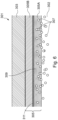
- Figure 5 shows a cross-section through a lined pipe 301 which comprises a carbon steel host pipe 303 and a liner 305, now in accordance with the present invention.
- the carbon steel host pipe 303 is provided with corrosion resistance by installation of the liner 305 (using a reduction and reversion process) which remains in tight contact with the interior surface of the carbon steel host pipe 303.
- the liner 305 differs from the liner 205 illustrated in Figure 2 in at least one key detail.
- Figure 7 is an exploded view of the cross-section through the lined pipe 301 shown in Figure 5 , for ease of reference.
- the liner 305 comprises an outer polymer layer, polymer pipe 305B, which is bonded to barrier layer 311 using an adhesive 313. It is the outer polymer pipe 305B which contacts the host pipe 303 after the liner 305 has reverted. It will be understood that the outer polymer pipe is substantially cylindrical, hence describing same as a "pipe”. As noted elsewhere it might equivalently be termed an outermost polymer layer.
- inner polymer layer pipe 205A has been replaced with a porous pipe 305A which is bonded to the barrier layer 311, on the opposite side of the barrier layer 311 from the outer polymer pipe 305B, using a (preferably porous) adhesive 315.
- porous pipe 305A is also substantially cylindrical, hence describing same as a "pipe”. As noted elsewhere it might equivalently be termed an innermost polymer layer.
- Figure 6 shows the lined pipe 301 being used in live hydrocarbon service.
- gas (as indicated by reference numeral 307) is allowed to pass freely between the internal bore 302 of the lined pipe 301 and the barrier layer 311 such that there is no accumulation of gas within the layers of the liner 305 that would otherwise pose a risk of collapse.
- the purpose of the porous pipe 305A is expressly to permit the passage of gas 307 (or liquid) through the inner layer (or layers) of the liner 305, between the internal bore 302 of the lined pipe 301 and the barrier layer 311 and vice versa.
- This is in contrast to the polymer liner 105 shown in Figures 1 and 2 and the inner polymer pipe 205A shown in Figures 3 and 4 which substantially prevent the passage of gas 107,207.
- the porous pipe 305A comprises a polymer material and purposely has a plurality of pores or interstices which permit the passage of gas (or liquid), whereas the polymer liner 105 shown in Figures 1 and 2 and the inner polymer pipe 205A shown in Figures 3 and 4 is substantially solid (i.e. does not permit the passage of gas or liquid).
- the invention does not assume that gas permeation is inevitable and simply seek to mitigate the resulting risk; rather, the invention prevents permeation and furthermore prevents the resulting risk being moved from an annulus between a liner and a host pipe to an interface between a barrier layer and an inner polymer pipe (of a barrier pipe).
- the invention prevents permeation and furthermore prevents the resulting risk being moved from an annulus between a liner and a host pipe to an interface between a barrier layer and an inner polymer pipe (of a barrier pipe).
- a further benefit of the invention which follows is that the necessity for CRA materials will be significantly reduced because the carbon steel host pipe is no longer being exposed to corrosive products in service. This will result in a significant reduction in the total cost as well as in the environmental impact of such pipelines. Even if the barrier layer comprises a CRA material, this would still represent a significant reduction in CRA material overall because a CRA barrier layer would contain only a small fraction of the amount of CRA that would be used to line or clad the same length of pipe.
- the host pipe is described as being a carbon steel host pipe, it will be understood that the material of the host pipe is incidental and may in fact comprise any material; in other words the liner of the invention may be used as a liner for any kind of pipe. What is important is the structure and/or features of the liner which address the problems of gas permeation through conventional liners.
- each layer could comprise multiple layers; in other words, one or both pipes could comprise a laminate or other arrangement of multiple layers.
- the preferred technique for installation of the liner is the reduction (via a swaging die), insertion and reversion technique developed by British Gas and subsequently refined for the oil and gas industry by Swagelining Limited
- the invention is not limited to or by any particular method of inserting the liner.
- Such a technique is employed in the Tite Liner ® system developed by United Pipeline Systems.
- the liner may be folded or otherwise deformed into an H-, U- or C-shaped cross-section, inserted into the host pipe, and then allowed or caused to return to its original shape by application of heat and/or pressure for example. This is sometimes referred to as close-fit lining or fold and form lining.
- the liner may be inserted using the so-called slip-lining technique, whereby the liner is selected to have a smaller outer diameter than the inner diameter of the host pipe, and after (or during) insertion the annular space between the liner and the host pipe is sealed or grouted.
- Figure 8 shows (in exploded view) a partial cross-section through a lined pipe 401 which comprises a flexible host pipe 403 and an alternative liner 405, not in accordance with the present invention.
- the liner 405 differs from the liner 305 illustrated in Figures 6 and 7 in that there is no outer polymer layer. Instead, it is the barrier layer 411 which contacts the host pipe 403.
- the liner comprises an inner porous pipe 405A which is bonded to the barrier layer 411, on the opposite side of the barrier layer 411 from the host pipe 403, using a (preferably porous) adhesive 415.
- Examples of flexible host pipe in which such a liner 405 may be deployed include reinforced thermoplastic pipe and flexible pipes and risers such as may be used for hydrocarbon service.
- gas is allowed to pass freely between the internal bore (not shown) of the lined pipe 401 and the barrier layer 411 such that there is no accumulation of gas within the layers of the liner 405 that would otherwise pose a risk of collapse, and gas is prevented from permeating to and accumulating in the annulus between the barrier layer and the flexible host pipe 403.
- the innermost polymer pipe is extruded (in cylindrical form) from material which is accepted as suitable for being in contact with the transported products.
- the material could comprise commodity polymer grade porous or sintered porous materials such as polyethylene (PE), PE-RT, UHMWPE or be selected from the PP range of polymer grades.
- PE polyethylene
- PE-RT PE-RT
- UHMWPE UHMWPE
- higher grade engineering polymers such as PVDF or PTFE may be used in porous form.
- materials may be hydrophobic or hydrophilic in nature. Pore size, pore density and wall thickness of the porous innermost pipe will be determined in response to the demands of the application, i.e. the service environment for which it is intended.
- the innermost polymer pipe could comprise a composite of different materials as may be appropriate, and it is also anticipated that the innermost polymer pipe could comprise multiple layers of different (or the same) materials. In this way different properties of different materials can be exploited. For example, one layer might provide hydrophobic or hydrophilic properties and another sub-layer might provide mechanical strength. Each layer may be extruded in turn. A porous adhesive may be applied between the layers to join them together while preserve the porosity of the layer as a whole.
- the thickness of the innermost polymer pipe can be calculated or otherwise determined (for example from a look up table) at the pipe design stage and will depend upon the properties of the selected materials. For example, a material with high modulus enables the innermost polymer pipe to be thinner than is possible with a lower modulus material.
- the innermost polymer pipe may be allowed to cool sufficiently prior to attaching the metallic foil which will form the barrier layer.
- the metallic foil may comprise aluminium, stainless steel or any corrosion resistant alloy such as Monel, Incoloy, Inconel or titanium or other such metallic material that is appropriate for the service environment. Wall thickness of the metallic foil may vary depending upon the service environment and the material properties but manufacturing tolerances are such that foils are available in thickness ranges from 0.009mm and above.
- the metallic foil is generally attached to the innermost polymer pipe by an adhesive.
- the adhesive may be solid but is preferably porous and may be heat sensitive.
- the adhesive may take the form of an adhesive tape.
- the adhesive may be applied directly to the external surface of the innermost pipe immediately before applying the metallic layer.
- the adhesive tape can be wound around the innermost pipe.
- the adhesive layer may be pre-applied to the inner surface of the metallic layer in preparation for application to the external surface of the innermost polymer pipe.
- the metallic foil may be applied to the innermost polymer pipe by a continuous axial operation (i.e. in discrete circumferential sections) or by spirally winding the metallic foil around the innermost polymer pipe. In either application, the metallic layer will overlap to ensure there is no gap in the protective layer provided by the metallic foil. It is important that there is no pathway for the transit of permeated gas from the transported fluid to reach the carbon steel host pipe.
- Application bonding (or sealing) of the metallic foil may be facilitated by either the use of the adhesive only where the overlap is heat sealed or by an option based on welding of the overlapping edges of the metallic foil or by an option of welding in combination with adhesive.
- the foil may be welded using - for example - very low amperage (low heat) Gas Thermal Arc Welding (GTAW) or by ultrasonic welding. Typically, these methods produce a fusion bond through very low heat generative processes.
- GTAW Gas Thermal Arc Welding
- the fusion of the metallic foil overlap seam should not present a risk of damage to the innermost polymer pipe as a result of heat originating from the welding process. It should be noted that when the process selected is based on a combination of low temperature welding together with pre-applied adhesive, the area adjacent to the weld area on both sides of the metallic foil may be kept free of adhesive to avoid contamination of the fusion joint. When no welding operation is to be used, then the pre-applied adhesive may cover the full area of the metallic foil on both sides and may be heat sealed during the foil wrapping operation.
- this method can also be used to produce a composite pipe; i.e. a pipe in which the outermost polymer pipe effectively constitutes the host pipe.
- the outermost polymer pipe can be formed by extrusion coating of the selected polymer material over the metallic foil layer using an annular die. A vacuum applied under the annular extruded melt can be employed to draw the outermost pipe onto the outer layer of metallic foil and adhesive and thereby ensure it fits tightly. Thereafter, the fully formed liner may be cooled to a completed condition and may be cut to length.
- the material of the outermost polymer pipe may comprise one or more solid materials selected from the group comprising PE, PE-RT, UHMWPE, PP, PVDF and PTFE.
- multilayer liner stalks may be manufactured in accordance with the guidance set out above to pre-set lengths to suit the length of the carbon steel stalks being lined.
- a modular extrusion facility may be employed to allow multi-layer liner to be manufactured on the pipeline site, which may be a spoolbase, a bundle site or a double / quad / hex jointing facility. It is foreseen that a liner may be extruded directly on to a suitable reel (or reels) for onward shipment to its destination.
- the liner be inserted in a host pipe using a reduction and reversion process, such as Swagelining ® or roll-down. It will also be understood that other methods of lining a pipe with such a liner are possible (as intimated above with examples). The following short description of the preferred process allows certain preferred and optional features of the liner to be understood in the context of the manner in which the liner is to be installed.
- the external diameter of the (multi-layer) liner Prior to insertion in a host pipe, the external diameter of the (multi-layer) liner is greater than the internal diameter of the host pipe.
- the liner is temporarily reduced in diameter, for example by pulling it through a swaging die or reduction rollers, such that the external diameter of the liner is less than the internal diameter of the host pipe.
- the liner is then inserted into the host pipe, for example by maintaining tension and continuing to pull the liner through the host pipe. Once the liner has been inserted into the host pipe, it is allowed to revert towards its original size, for example by release of the pulling tension. The liner thus forms a tight fit within the host pipe.
- the external diameter of the outermost polymer pipe is greater than the internal diameter of the host pipe. It is optional whether the external diameter of the inner polymer pipe is greater than the internal diameter of the host pipe.
- the invention provides an improved pipe liner and associated methods, including a method of manufacturing the improved pipe liner and a method of lining a host pipe with such a pipe liner.
- the invention solves the problem of gas permeation through a polymer liner in hydrocarbon service which can result in corrosion of the host pipe and can also cause liner collapse. Corrosion occurs due to contact between corrosive species and the host pipe itself. Gases can also accumulate in an annulus between or within the liner and the host pipe and expand during operational de-pressurisation of the pipeline, causing collapse of the liner.
- the improved pipe liner comprises a barrier layer, which prevents permeation through the liner, surrounding an inner polymer pipe and covered by an outer polymer pipe.
- the inner polymer pipe is porous which permits free movement of gas between the internal bore of a lined pipe and the barrier layer, so as to prevent accumulation of gases anywhere in the lined pipe, while ensuring that gases do not permeate to, and damage, the host pipe.
- the liner can be inserted using Swagelining, roll-down, or any other suitable close-fit lining techniques, without compromising the effectiveness of the barrier layer.
- porous is technically and functionally distinct from the term “permeable”, and in any case it should be understood that standard polymer materials are generally considered to be impermeable, certainly within the specific range of temperatures and pressures in the environment at which they are normally targeted.
- Barrier pipe addresses the issue that it is inevitable that some gas or liquid will eventually permeate through the polymer liner, and does so by locating a metallic (e.g. aluminium) barrier layer within the liner. Gas or liquid which permeates through the innermost layer of the barrier pipe will be effectively halted at the metallic barrier layer.
- a metallic e.g. aluminium
- the Applicant has realised that because the liner material is substantially impermeable, gas that has transited through the inner layer by permeation will eventually accumulate at the barrier layer and will effectively be trapped there, shifting the risk of liner collapse from the annulus between the liner and the host pipe to the interface between the barrier pipe and the innermost layer of the barrier pipe.
- the Applicant's invention facilitates free transit of gas in all directions, with immediate effect, because the innermost layer of the liner is porous. There is no gradual transit phenomenon over time (i.e. no permeation) and therefore accumulation of the kind discussed above is not possible.
- the porous nature of the innermost layer thereby eliminates the risk of collapse.
Landscapes
- Engineering & Computer Science (AREA)
- General Engineering & Computer Science (AREA)
- Mechanical Engineering (AREA)
- Manufacturing & Machinery (AREA)
- Rigid Pipes And Flexible Pipes (AREA)
- Laminated Bodies (AREA)
- Lining Or Joining Of Plastics Or The Like (AREA)
Claims (18)
- Un revêtement (305) permettant de revêtir un tuyau d'accueil (303) ou un tuyau composite, le revêtement ou le tuyau composite comprenant :un tuyau intérieur en polymère (305A) ; etune couche barrière (311) entourant le tuyau intérieur en polymère ;dans lequel le tuyau intérieur en polymère est poreux, comportant plusieurs pores ou interstices qui permettent le passage du gaz (307), de sorte que le tuyau intérieur en polymère permet la libre circulation du gaz entre l'alésage interne (302) et la couche barrière, empêchant l'accumulation de gaz à l'intérieur des couches du revêtement ou du tuyau composite ;dans lequel le tuyau intérieur en polymère est collé à la couche barrière avec un adhésif (315) ;dans lequel le revêtement ou le tuyau composite comprend en outre un tuyau extérieur en polymère (305B) entourant la couche barrière ; etdans lequel le tuyau extérieur en polymère n'est pas poreux.
- Le revêtement ou le tuyau composite de la revendication 1, dans lequel le tuyau intérieur en polymère et/ou le tuyau extérieur en polymère comprend un ou plusieurs matériaux choisis parmi le PE, le PE-RT, l'UHMWPE, le PP, le PVDF et le PTFE.
- Le revêtement ou le tuyau composite de l'une des revendications précédentes, dans lequel le tuyau intérieur en polymère comprend un matériau hydrophobe ou hydrophile.
- Le revêtement ou le tuyau composite de l'une des revendications précédentes, dans lequel le tuyau intérieur en polymère comprend deux ou plusieurs couches collées par un adhésif poreux.
- Le revêtement ou le tuyau composite de l'une des revendications précédentes, dans lequel la couche barrière comprend une feuille métallique, éventuellement choisie parmi l'aluminium, l'acier inoxydable, le Monel, l'Incoloy, l'Inconel ou le titane.
- Le revêtement ou le tuyau composite de l'une des revendications précédentes, dans lequel la couche barrière est fixée au tuyau intérieur en polymère par un adhésif poreux, ou dans lequel la couche barrière est fixée au tuyau intérieur en polymère par un ruban adhésif sensible à la température et/ou à la pression.
- Le revêtement ou le tuyau composite de l'une des revendications précédentes, dans lequel la couche barrière comprend plusieurs sections circonférentielles séparées se chevauchant, ou dans lequel la couche barrière est enroulée autour du tuyau intérieur en polymère, et dans lequel les spires successives de la couche barrière se chevauchent, la couche barrière étant éventuellement scellée par des soudures au niveau des chevauchements.
- Le revêtement ou le tuyau composite de l'une des revendications précédentes, dans lequel le tuyau extérieur en polymère est extrudé sur la couche barrière.
- Le procédé de fabrication d'un revêtement (305) ou d'un tuyau composite, consistant à :extruder un tuyau intérieur en polymère (305A) ;entourer le tuyau intérieur en polymère avec une couche barrière (311) ; et à entourer la couche barrière avec un tuyau extérieur en polymère ;dans lequel le tuyau intérieur en polymère est poreux, comportant plusieurs pores ou interstices qui permettent le passage du gaz (307), de sorte que le tuyau intérieur en polymère permet la libre circulation du gaz entre l'alésage interne (302) et la couche barrière, empêchant l'accumulation de gaz à l'intérieur des couches du revêtement ou du tuyau composite ;dans lequel le tuyau intérieur en polymère est collé à la couche barrière avec un adhésif (315) ; etdans lequel le tuyau extérieur en polymère n'est pas poreux.
- Le procédé de la revendication 9, dans lequel le tuyau intérieur en polymère est extrudé à partir d'un ou de plusieurs matériaux poreux ou d'un ou de plusieurs matériaux frittés.
- Le procédé de la revendication 9 ou 10, dans lequel le tuyau intérieur en polymère comprend deux ou plusieurs couches, et consistant à extruder la deuxième couche et chaque couche suivante sur la couche précédente ainsi qu'à fournir un adhésif poreux entre les couches.
- Le procédé de l'une des revendications 9 à 11, consistant à déterminer la taille des pores, la densité des pores et/ou l'épaisseur de la paroi du tuyau intérieur en polymère en fonction de l'environnement de service auquel le revêtement ou le tuyau composite est destiné, et/ou en fonction des propriétés du matériau du tuyau intérieur en polymère.
- Le procédé de l'une des revendications 9 à 12, consistant à sélectionner le matériau de la couche barrière en fonction de l'environnement de service auquel le revêtement ou le tuyau composite est destiné, et/ou à sélectionner l'épaisseur de la couche barrière en fonction des propriétés du matériau et/ou de l'environnement de service auquel le revêtement ou le tuyau composite est destiné.
- Le procédé de l'une des revendications 9 à 13, consistant à appliquer un adhésif ou un ruban adhésif sur la surface externe du tuyau intérieur en polymère ou sur la surface interne de la couche barrière, puis à appliquer la couche barrière sur le tuyau intérieur en polymère.
- Le procédé de l'une des revendications 9 à 14, dans lequel la couche barrière est appliquée sur le tuyau intérieur en polymère dans le cadre d'un mouvement axial continu, ou dans lequel la couche barrière est enroulée en spirale autour du tuyau intérieur en polymère, et dans lequel les spires successives de la couche barrière se chevauchent, et dans lequel le procédé consiste éventuellement à sceller la couche barrière par thermoscellage ou par soudage des bords de la couche barrière se chevauchant.
- Le procédé de l'une des revendications 14 à 22, consistant en outre à extruder le tuyau extérieur en polymère sur la couche barrière, éventuellement en utilisant une matrice annulaire et en appliquant un vide pour attirer le tuyau extérieur en polymère sur la couche barrière.
- Le procédé de l'une des revendications 14 à 24, consistant à fabriquer le revêtement à une longueur prédéfinie adaptée au tuyau d'accueil auquel le revêtement est destiné, ou dans lequel le revêtement ou le tuyau composite est extrudé directement sur une ou plusieurs bobines pour être expédié ultérieurement.
- Le procédé de revêtement d'un tuyau d'accueil, consistant à :fournir un revêtement conforme à l'une des revendications 1 à 8 ;réduire temporairement le diamètre extérieur du revêtement de manière à ce qu'il soit inférieur au diamètre intérieur du tuyau d'accueil ;insérer le revêtement dans le tuyau d'accueil ; et àpermettre au revêtement de revenir à sa taille d'origine à l'intérieur du tuyau d'accueil.
Applications Claiming Priority (2)
| Application Number | Priority Date | Filing Date | Title |
|---|---|---|---|
| GB1915755.1A GB2588641B (en) | 2019-10-30 | 2019-10-30 | Improved pipe liner and associated methods |
| PCT/GB2020/052710 WO2021084236A1 (fr) | 2019-10-30 | 2020-10-26 | Chemise de tuyau améliorée et procédés associés |
Publications (3)
| Publication Number | Publication Date |
|---|---|
| EP4051944A1 EP4051944A1 (fr) | 2022-09-07 |
| EP4051944B1 true EP4051944B1 (fr) | 2023-09-13 |
| EP4051944C0 EP4051944C0 (fr) | 2023-09-13 |
Family
ID=68769033
Family Applications (1)
| Application Number | Title | Priority Date | Filing Date |
|---|---|---|---|
| EP20803236.7A Active EP4051944B1 (fr) | 2019-10-30 | 2020-10-26 | Chemise de tuyau améliorée et procédés associés |
Country Status (6)
| Country | Link |
|---|---|
| US (1) | US11796091B2 (fr) |
| EP (1) | EP4051944B1 (fr) |
| AU (1) | AU2020373211B2 (fr) |
| CA (1) | CA3153680C (fr) |
| GB (1) | GB2588641B (fr) |
| WO (1) | WO2021084236A1 (fr) |
Families Citing this family (11)
| Publication number | Priority date | Publication date | Assignee | Title |
|---|---|---|---|---|
| US12169043B2 (en) | 2021-05-14 | 2024-12-17 | Saudi Arabian Oil Company | Extruded aliphatic polyketone permeation barrier for spoolable composite pipes |
| FR3130925B1 (fr) * | 2021-12-17 | 2023-12-15 | Saipem Sa | Conduite pour le transport de fluides à tube en acier avec chemisage de protection muni de fentes pour l’évacuation du gaz accumulé sous le chemisage |
| GB2632498A (en) * | 2023-08-10 | 2025-02-12 | Subsea 7 Ltd | Lined pipelines |
| AU2024319487A1 (en) | 2023-08-10 | 2026-02-19 | Subsea 7 Limited | Lined pipelines |
| AU2024320302A1 (en) | 2023-08-10 | 2026-02-19 | Subsea 7 Limited | Lined pipelines |
| GB2632481A (en) * | 2023-08-10 | 2025-02-12 | Subsea 7 Ltd | Lined pipelines |
| GB2632482A (en) | 2023-08-10 | 2025-02-12 | Subsea 7 Ltd | Lined pipelines |
| CN117759789A (zh) * | 2023-12-30 | 2024-03-26 | 湖南振辉管业有限公司 | 一种金属内衬多层复合管及其制造方法 |
| CN117570282A (zh) * | 2023-12-30 | 2024-02-20 | 湖南振辉管业有限公司 | 一种端面包边密封的多层复合管及其制造方法 |
| CN117759790A (zh) * | 2023-12-30 | 2024-03-26 | 湖南振辉管业有限公司 | 一种端面包边的承插式多层管材及其制造方法 |
| NL2037015B1 (en) * | 2024-02-13 | 2025-08-20 | Pipelife Nederland Bv | Non-permeable pipe |
Family Cites Families (19)
| Publication number | Priority date | Publication date | Assignee | Title |
|---|---|---|---|---|
| US4436778A (en) * | 1981-10-05 | 1984-03-13 | Ball Corporation | Multilayer tubular body with uncentered barrier layer |
| GB2186340B (en) | 1986-02-10 | 1990-08-01 | British Gas Plc | Method for lining a pipe or main |
| US6240612B1 (en) | 1988-05-09 | 2001-06-05 | British Gas Plc | Method for the lining of existing pipes |
| US6016848A (en) * | 1996-07-16 | 2000-01-25 | W. L. Gore & Associates, Inc. | Fluoropolymer tubes and methods of making same |
| DE19801798A1 (de) * | 1997-12-23 | 1999-06-24 | Linde Ag | Förderschlauch für Feststoffe insbesondere mit tiefen Temperaturen |
| GB2336885B (en) * | 1998-04-29 | 2002-11-13 | Glynwed Pipe Systems Ltd | Improvements in or relating to pipes |
| US6220079B1 (en) | 1998-07-22 | 2001-04-24 | Safety Liner Systems, L.L.C. | Annular fluid manipulation in lined tubular systems |
| GB0025301D0 (en) | 2000-10-14 | 2000-11-29 | Boreas Consultants Ltd | Lined pipeline vent |
| US20030213596A1 (en) * | 2002-05-16 | 2003-11-20 | Davis Robert H. | Tubular goods and liners |
| US8127800B2 (en) * | 2005-02-28 | 2012-03-06 | Parker-Hannifin Corporation | Fire protective hose assembly |
| EP1974903A1 (fr) * | 2007-03-29 | 2008-10-01 | Tokai Rubber Industries, Ltd. | Tuyau à faible perméabilité au gaz |
| US9592648B2 (en) * | 2009-06-01 | 2017-03-14 | Gates Corporation | Low-permeation flexible fuel hose |
| FR2982795B1 (fr) | 2011-11-21 | 2013-11-29 | Moderne D Isolation Soc | Complexe isolant |
| GB201303619D0 (en) * | 2013-02-28 | 2013-04-17 | Valpar Ind Ltd | Improved beverage dispensing tubing |
| CA2897301C (fr) * | 2014-07-14 | 2020-06-02 | Fyfe Co. Llc | Revetement de tuyau etanche et tres resistant |
| EP3189260A4 (fr) * | 2014-09-02 | 2018-01-17 | National Oilwell Varco Denmark I/S | Tuyau flexible non collé |
| GB2536492B (en) | 2015-03-20 | 2017-10-18 | Pioneer Lining Tech Ltd | Method of laying lined pipeline |
| GB2538549B (en) * | 2015-05-21 | 2018-02-28 | Pioneer Lining Tech Limited | Joining lined pipe sections |
| CN205877445U (zh) * | 2016-03-21 | 2017-01-11 | 洛阳国润新材料科技股份有限公司 | 一种石油化工用内外加强型防渗透复合管道 |
-
2019
- 2019-10-30 GB GB1915755.1A patent/GB2588641B/en active Active
-
2020
- 2020-10-26 WO PCT/GB2020/052710 patent/WO2021084236A1/fr not_active Ceased
- 2020-10-26 CA CA3153680A patent/CA3153680C/fr active Active
- 2020-10-26 US US17/642,430 patent/US11796091B2/en active Active
- 2020-10-26 AU AU2020373211A patent/AU2020373211B2/en active Active
- 2020-10-26 EP EP20803236.7A patent/EP4051944B1/fr active Active
Also Published As
| Publication number | Publication date |
|---|---|
| US20220341514A1 (en) | 2022-10-27 |
| CA3153680C (fr) | 2023-02-14 |
| WO2021084236A1 (fr) | 2021-05-06 |
| EP4051944A1 (fr) | 2022-09-07 |
| BR112022007261A2 (pt) | 2022-07-12 |
| GB201915755D0 (en) | 2019-12-11 |
| AU2020373211B2 (en) | 2025-08-14 |
| US11796091B2 (en) | 2023-10-24 |
| GB2588641A (en) | 2021-05-05 |
| AU2020373211A1 (en) | 2022-03-24 |
| EP4051944C0 (fr) | 2023-09-13 |
| GB2588641B (en) | 2022-04-20 |
| CA3153680A1 (fr) | 2021-05-06 |
Similar Documents
| Publication | Publication Date | Title |
|---|---|---|
| EP4051944B1 (fr) | Chemise de tuyau améliorée et procédés associés | |
| EP0507680B1 (fr) | Procédé de réalisation en continu d'une structure tubulaire souple comportant un feuil monocouche d'épaisseur micrométrique incorporé et structures tubulaires souples réalisées selon ce procédé | |
| EP0507679B1 (fr) | Procédé de réalisation en continu d'une structure tubulaire souple comportant une feuille multicouche d'épaisseur micrométrique incorporé et structures tubulaires souples réalisées selon ce procédé | |
| RU2709588C2 (ru) | Термопластичная композитная труба с многослойной промежуточной прослойкой | |
| JP5666551B2 (ja) | 低温流体の搬送の為の複合ホース | |
| US20130025735A1 (en) | Flexible pipe and process for production thereof | |
| KR20130103498A (ko) | 강성 인서트를 지니는 유체 취급 어셈블리 | |
| JP2022118001A (ja) | 多層中間層体を有する熱可塑性複合管 | |
| US8714204B2 (en) | Free venting pipe and method of manufacture | |
| US20140238525A1 (en) | Thermoplastic composite pipe with longitudinal reinforcement | |
| US20160076675A1 (en) | Flexible Pipe with Corrosion Resistant Layer | |
| WO2022183170A1 (fr) | Tuyau non collé en plastique renforcé | |
| US20100003440A1 (en) | Tubular Members and Method of Forming Same | |
| WO2024022616A2 (fr) | Barrière de perméation et procédé de fabrication | |
| US20120238428A1 (en) | Method for providing a wound up fiber reinforced tube | |
| BR112022007261B1 (pt) | Revestidor de tubo aprimorado e métodos associados | |
| EP3477176A1 (fr) | Procédé de fabrication d'un tube revêtu d'une gaine intérieure | |
| WO2025032261A1 (fr) | Pipelines revêtus | |
| AU2024320302A1 (en) | Lined pipelines | |
| AU2024320283A1 (en) | Lined pipelines | |
| EP1316751A2 (fr) | Tuyau multicouche | |
| CN117450334A (zh) | 一种输氢用高压力钢丝网增强塑料复合管材及其制造方法 |
Legal Events
| Date | Code | Title | Description |
|---|---|---|---|
| STAA | Information on the status of an ep patent application or granted ep patent |
Free format text: STATUS: UNKNOWN |
|
| STAA | Information on the status of an ep patent application or granted ep patent |
Free format text: STATUS: THE INTERNATIONAL PUBLICATION HAS BEEN MADE |
|
| PUAI | Public reference made under article 153(3) epc to a published international application that has entered the european phase |
Free format text: ORIGINAL CODE: 0009012 |
|
| STAA | Information on the status of an ep patent application or granted ep patent |
Free format text: STATUS: REQUEST FOR EXAMINATION WAS MADE |
|
| 17P | Request for examination filed |
Effective date: 20220525 |
|
| AK | Designated contracting states |
Kind code of ref document: A1 Designated state(s): AL AT BE BG CH CY CZ DE DK EE ES FI FR GB GR HR HU IE IS IT LI LT LU LV MC MK MT NL NO PL PT RO RS SE SI SK SM TR |
|
| DAV | Request for validation of the european patent (deleted) | ||
| DAX | Request for extension of the european patent (deleted) | ||
| GRAP | Despatch of communication of intention to grant a patent |
Free format text: ORIGINAL CODE: EPIDOSNIGR1 |
|
| STAA | Information on the status of an ep patent application or granted ep patent |
Free format text: STATUS: GRANT OF PATENT IS INTENDED |
|
| RIC1 | Information provided on ipc code assigned before grant |
Ipc: B32B 27/32 20060101ALI20230516BHEP Ipc: B32B 27/30 20060101ALI20230516BHEP Ipc: B32B 27/08 20060101ALI20230516BHEP Ipc: B32B 15/20 20060101ALI20230516BHEP Ipc: B32B 15/18 20060101ALI20230516BHEP Ipc: B32B 15/085 20060101ALI20230516BHEP Ipc: B32B 15/08 20060101ALI20230516BHEP Ipc: B32B 7/12 20060101ALI20230516BHEP Ipc: B32B 1/08 20060101ALI20230516BHEP Ipc: B29C 63/34 20060101ALI20230516BHEP Ipc: B29C 55/30 20060101ALI20230516BHEP Ipc: F16L 11/04 20060101ALI20230516BHEP Ipc: F16L 9/147 20060101ALI20230516BHEP Ipc: F16L 58/10 20060101ALI20230516BHEP Ipc: F16L 55/165 20060101AFI20230516BHEP |
|
| INTG | Intention to grant announced |
Effective date: 20230605 |
|
| GRAS | Grant fee paid |
Free format text: ORIGINAL CODE: EPIDOSNIGR3 |
|
| GRAA | (expected) grant |
Free format text: ORIGINAL CODE: 0009210 |
|
| STAA | Information on the status of an ep patent application or granted ep patent |
Free format text: STATUS: THE PATENT HAS BEEN GRANTED |
|
| AK | Designated contracting states |
Kind code of ref document: B1 Designated state(s): AL AT BE BG CH CY CZ DE DK EE ES FI FR GR HR HU IE IS IT LI LT LU LV MC MK MT NL NO PL PT RO RS SE SI SK SM TR |
|
| RBV | Designated contracting states (corrected) |
Designated state(s): AL AT BE BG CH CY CZ DE DK EE ES FI FR GR HR HU IE IS IT LI LT LU LV MC MK MT NL NO PL PT RO RS SE SI SK SM TR |
|
| REG | Reference to a national code |
Ref country code: CH Ref legal event code: EP |
|
| REG | Reference to a national code |
Ref country code: DE Ref legal event code: R096 Ref document number: 602020017739 Country of ref document: DE |
|
| REG | Reference to a national code |
Ref country code: IE Ref legal event code: FG4D |
|
| U01 | Request for unitary effect filed |
Effective date: 20230919 |
|
| U07 | Unitary effect registered |
Designated state(s): AT BE BG DE DK EE FI FR IT LT LU LV MT NL PT SE SI Effective date: 20230925 |
|
| U20 | Renewal fee for the european patent with unitary effect paid |
Year of fee payment: 4 Effective date: 20231026 |
|
| REG | Reference to a national code |
Ref country code: NO Ref legal event code: T2 Effective date: 20230913 |
|
| PG25 | Lapsed in a contracting state [announced via postgrant information from national office to epo] |
Ref country code: GR Free format text: LAPSE BECAUSE OF FAILURE TO SUBMIT A TRANSLATION OF THE DESCRIPTION OR TO PAY THE FEE WITHIN THE PRESCRIBED TIME-LIMIT Effective date: 20231214 |
|
| PG25 | Lapsed in a contracting state [announced via postgrant information from national office to epo] |
Ref country code: RS Free format text: LAPSE BECAUSE OF FAILURE TO SUBMIT A TRANSLATION OF THE DESCRIPTION OR TO PAY THE FEE WITHIN THE PRESCRIBED TIME-LIMIT Effective date: 20230913 Ref country code: HR Free format text: LAPSE BECAUSE OF FAILURE TO SUBMIT A TRANSLATION OF THE DESCRIPTION OR TO PAY THE FEE WITHIN THE PRESCRIBED TIME-LIMIT Effective date: 20230913 Ref country code: GR Free format text: LAPSE BECAUSE OF FAILURE TO SUBMIT A TRANSLATION OF THE DESCRIPTION OR TO PAY THE FEE WITHIN THE PRESCRIBED TIME-LIMIT Effective date: 20231214 |
|
| PG25 | Lapsed in a contracting state [announced via postgrant information from national office to epo] |
Ref country code: IS Free format text: LAPSE BECAUSE OF FAILURE TO SUBMIT A TRANSLATION OF THE DESCRIPTION OR TO PAY THE FEE WITHIN THE PRESCRIBED TIME-LIMIT Effective date: 20240113 |
|
| PG25 | Lapsed in a contracting state [announced via postgrant information from national office to epo] |
Ref country code: ES Free format text: LAPSE BECAUSE OF FAILURE TO SUBMIT A TRANSLATION OF THE DESCRIPTION OR TO PAY THE FEE WITHIN THE PRESCRIBED TIME-LIMIT Effective date: 20230913 |
|
| PG25 | Lapsed in a contracting state [announced via postgrant information from national office to epo] |
Ref country code: SM Free format text: LAPSE BECAUSE OF FAILURE TO SUBMIT A TRANSLATION OF THE DESCRIPTION OR TO PAY THE FEE WITHIN THE PRESCRIBED TIME-LIMIT Effective date: 20230913 Ref country code: RO Free format text: LAPSE BECAUSE OF FAILURE TO SUBMIT A TRANSLATION OF THE DESCRIPTION OR TO PAY THE FEE WITHIN THE PRESCRIBED TIME-LIMIT Effective date: 20230913 Ref country code: IS Free format text: LAPSE BECAUSE OF FAILURE TO SUBMIT A TRANSLATION OF THE DESCRIPTION OR TO PAY THE FEE WITHIN THE PRESCRIBED TIME-LIMIT Effective date: 20240113 Ref country code: ES Free format text: LAPSE BECAUSE OF FAILURE TO SUBMIT A TRANSLATION OF THE DESCRIPTION OR TO PAY THE FEE WITHIN THE PRESCRIBED TIME-LIMIT Effective date: 20230913 Ref country code: CZ Free format text: LAPSE BECAUSE OF FAILURE TO SUBMIT A TRANSLATION OF THE DESCRIPTION OR TO PAY THE FEE WITHIN THE PRESCRIBED TIME-LIMIT Effective date: 20230913 Ref country code: SK Free format text: LAPSE BECAUSE OF FAILURE TO SUBMIT A TRANSLATION OF THE DESCRIPTION OR TO PAY THE FEE WITHIN THE PRESCRIBED TIME-LIMIT Effective date: 20230913 |
|
| PG25 | Lapsed in a contracting state [announced via postgrant information from national office to epo] |
Ref country code: PL Free format text: LAPSE BECAUSE OF FAILURE TO SUBMIT A TRANSLATION OF THE DESCRIPTION OR TO PAY THE FEE WITHIN THE PRESCRIBED TIME-LIMIT Effective date: 20230913 |
|
| REG | Reference to a national code |
Ref country code: CH Ref legal event code: PL |
|
| REG | Reference to a national code |
Ref country code: DE Ref legal event code: R097 Ref document number: 602020017739 Country of ref document: DE |
|
| PG25 | Lapsed in a contracting state [announced via postgrant information from national office to epo] |
Ref country code: MC Free format text: LAPSE BECAUSE OF FAILURE TO SUBMIT A TRANSLATION OF THE DESCRIPTION OR TO PAY THE FEE WITHIN THE PRESCRIBED TIME-LIMIT Effective date: 20230913 |
|
| PG25 | Lapsed in a contracting state [announced via postgrant information from national office to epo] |
Ref country code: CH Free format text: LAPSE BECAUSE OF NON-PAYMENT OF DUE FEES Effective date: 20231031 |
|
| PLBE | No opposition filed within time limit |
Free format text: ORIGINAL CODE: 0009261 |
|
| STAA | Information on the status of an ep patent application or granted ep patent |
Free format text: STATUS: NO OPPOSITION FILED WITHIN TIME LIMIT |
|
| PG25 | Lapsed in a contracting state [announced via postgrant information from national office to epo] |
Ref country code: MC Free format text: LAPSE BECAUSE OF FAILURE TO SUBMIT A TRANSLATION OF THE DESCRIPTION OR TO PAY THE FEE WITHIN THE PRESCRIBED TIME-LIMIT Effective date: 20230913 Ref country code: CH Free format text: LAPSE BECAUSE OF NON-PAYMENT OF DUE FEES Effective date: 20231031 |
|
| 26N | No opposition filed |
Effective date: 20240614 |
|
| PG25 | Lapsed in a contracting state [announced via postgrant information from national office to epo] |
Ref country code: IE Free format text: LAPSE BECAUSE OF NON-PAYMENT OF DUE FEES Effective date: 20231026 |
|
| PG25 | Lapsed in a contracting state [announced via postgrant information from national office to epo] |
Ref country code: IE Free format text: LAPSE BECAUSE OF NON-PAYMENT OF DUE FEES Effective date: 20231026 |
|
| U20 | Renewal fee for the european patent with unitary effect paid |
Year of fee payment: 5 Effective date: 20241002 |
|
| PG25 | Lapsed in a contracting state [announced via postgrant information from national office to epo] |
Ref country code: CY Free format text: LAPSE BECAUSE OF FAILURE TO SUBMIT A TRANSLATION OF THE DESCRIPTION OR TO PAY THE FEE WITHIN THE PRESCRIBED TIME-LIMIT; INVALID AB INITIO Effective date: 20201026 |
|
| PG25 | Lapsed in a contracting state [announced via postgrant information from national office to epo] |
Ref country code: HU Free format text: LAPSE BECAUSE OF FAILURE TO SUBMIT A TRANSLATION OF THE DESCRIPTION OR TO PAY THE FEE WITHIN THE PRESCRIBED TIME-LIMIT; INVALID AB INITIO Effective date: 20201026 |
|
| U20 | Renewal fee for the european patent with unitary effect paid |
Year of fee payment: 6 Effective date: 20251022 |
|
| PG25 | Lapsed in a contracting state [announced via postgrant information from national office to epo] |
Ref country code: TR Free format text: LAPSE BECAUSE OF FAILURE TO SUBMIT A TRANSLATION OF THE DESCRIPTION OR TO PAY THE FEE WITHIN THE PRESCRIBED TIME-LIMIT Effective date: 20230913 |
|
| PGFP | Annual fee paid to national office [announced via postgrant information from national office to epo] |
Ref country code: NO Payment date: 20251028 Year of fee payment: 6 |