EP4051990B1 - Tragbarer artikel mit einer sensorvorrichtung - Google Patents
Tragbarer artikel mit einer sensorvorrichtung Download PDFInfo
- Publication number
- EP4051990B1 EP4051990B1 EP20816574.6A EP20816574A EP4051990B1 EP 4051990 B1 EP4051990 B1 EP 4051990B1 EP 20816574 A EP20816574 A EP 20816574A EP 4051990 B1 EP4051990 B1 EP 4051990B1
- Authority
- EP
- European Patent Office
- Prior art keywords
- sensor
- sensor device
- data
- wearable article
- over
- Prior art date
- Legal status (The legal status is an assumption and is not a legal conclusion. Google has not performed a legal analysis and makes no representation as to the accuracy of the status listed.)
- Active
Links
Images


Classifications
-
- H—ELECTRICITY
- H04—ELECTRIC COMMUNICATION TECHNIQUE
- H04L—TRANSMISSION OF DIGITAL INFORMATION, e.g. TELEGRAPHIC COMMUNICATION
- H04L67/00—Network arrangements or protocols for supporting network services or applications
- H04L67/01—Protocols
- H04L67/12—Protocols specially adapted for proprietary or special-purpose networking environments, e.g. medical networks, sensor networks, networks in vehicles or remote metering networks
-
- G—PHYSICS
- G08—SIGNALLING
- G08C—TRANSMISSION SYSTEMS FOR MEASURED VALUES, CONTROL OR SIMILAR SIGNALS
- G08C19/00—Electric signal transmission systems
-
- G—PHYSICS
- G01—MEASURING; TESTING
- G01D—MEASURING NOT SPECIALLY ADAPTED FOR A SPECIFIC VARIABLE; ARRANGEMENTS FOR MEASURING TWO OR MORE VARIABLES NOT COVERED IN A SINGLE OTHER SUBCLASS; TARIFF METERING APPARATUS; MEASURING OR TESTING NOT OTHERWISE PROVIDED FOR
- G01D21/00—Measuring or testing not otherwise provided for
-
- G—PHYSICS
- G01—MEASURING; TESTING
- G01D—MEASURING NOT SPECIALLY ADAPTED FOR A SPECIFIC VARIABLE; ARRANGEMENTS FOR MEASURING TWO OR MORE VARIABLES NOT COVERED IN A SINGLE OTHER SUBCLASS; TARIFF METERING APPARATUS; MEASURING OR TESTING NOT OTHERWISE PROVIDED FOR
- G01D9/00—Recording measured values
- G01D9/005—Solid-state data loggers
-
- H—ELECTRICITY
- H04—ELECTRIC COMMUNICATION TECHNIQUE
- H04L—TRANSMISSION OF DIGITAL INFORMATION, e.g. TELEGRAPHIC COMMUNICATION
- H04L12/00—Data switching networks
- H04L12/28—Data switching networks characterised by path configuration, e.g. LAN [Local Area Networks] or WAN [Wide Area Networks]
- H04L12/40—Bus networks
-
- H—ELECTRICITY
- H04—ELECTRIC COMMUNICATION TECHNIQUE
- H04L—TRANSMISSION OF DIGITAL INFORMATION, e.g. TELEGRAPHIC COMMUNICATION
- H04L69/00—Network arrangements, protocols or services independent of the application payload and not provided for in the other groups of this subclass
- H04L69/26—Special purpose or proprietary protocols or architectures
Definitions
- the present invention is directed towards a sensor device, wearable article, system and method.
- Sensor devices can communicate with one or more master devices over a serial protocol.
- Example serial protocols include Serial Peripheral Interface (SPI), Inter-Integrated Circuit (I2C), Controller Area Network (CAN), and Recommended Standard 232 (RS-232).
- SPI Serial Peripheral Interface
- I2C Inter-Integrated Circuit
- CAN Controller Area Network
- RS-232 Recommended Standard 232
- many sensor devices may be connected to the master device over one or more shared communication lines. Beneficially, this reduces the number of physical communication lines which can reduce the cost and complexity of the resultant sensor system. This is particularly advantageous for wearable articles such as garments as having many communication lines can reduce the comfort and physical appearance of the wearable article.
- each sensor device only has a limited time access to the communication lines for sending data to the master device. This means that data communicated to the master device may have a lower sampling rate than the available sampling rate of the sensor device.
- each sensor device may have a unique, unalterable, factory-programmed identifier. This increases the burden on the master device as the master device has to obtain these identifiers prior to performing communication with the sensor devices and increases the risk of error due to the use of an incorrect identifier.
- US 2007/0152812 discloses a garment with an embedded electronic temperature sensor.
- the temperature sensor is connected to a garment-mounted module referred to as a WEM.
- the WEM communicates with the temperature sensor over a 1-wire protocol.
- the temperature sensor has a lasered ROM storing a unique identifier and a buffer for storing temperature values.
- EP 3370367 A1 discloses a system comprising a headset and a communication unit coupled by a link for transporting power and bidirectional data traffic.
- a wearable article comprising a sensor device.
- the sensor device comprises a sensor module.
- the sensor device comprises a buffer arranged to store time-series sensor data sensed by the sensor module.
- the sensor device comprises an input-output interface arranged to send and receive data over a bidirectional line.
- the sensor device is therefore arranged to store time series sensor data in a buffer. This allows the sensor device to temporarily store data prior to transmission over the input-output interface. This is beneficial as the sensor device is generally only able to transmit data over the bidirectional line for a limited period of time. This is because the sensor device is unable to transmit data over the bidirectional line when other devices such as other sensor devices or a master device are utilising the bidirectional line bus for data transmission.
- the buffer therefore enables the sensor device to locally store time-series sensor data until a command is received from a master device for transmitting data over the input-output interface.
- the time series sensor data stored in the buffer may comprise 2 or more samples of sensor data, 5 or more samples of sensor data, 10 or more samples of sensor data, 50 or more samples of sensor data, 100 or more samples of sensor data, 500 or more samples of sensor data, or 1000 or more samples of sensor data.
- the buffer may be arranged to store up to or more than 10 minutes of data sensed by the sensor module, up to or more than 30 minutes of data sensed by the sensor module, up to or more than 1 hour of data sensed by the sensor module, up to or more than 6 hours of data sensed by the sensor module, up to or more than 12 hours of data sensed by the sensor module, up to or more than 24 hours of data sensed by the sensor module, up to or more than 1 week of data sensed by the sensor module, or up to or more than 1 month of data sensed by the sensor module.
- the buffer may have a storage capacity of at least 500 bytes, at least one 1 kilobyte, at least 5 kilobytes, at least 50 kilobytes, at least 500 kilobytes, at least 1 megabyte, at least 5 megabytes, at least 50 megabytes, at least 60 megabytes, at least 100 megabytes, at least 200 megabytes, or at least 250 megabytes. It will be appreciated that there is no required upper limit to the storage capacity of the buffer particularly considering the continual development in memory devices. At the time of writing, it may be desirable that the buffer does not have a storage capacity of more 8 gigabytes due to physical size considerations when integrating the sensor device in a wearable article such as a garment. However, it will be appreciated that as the physical size of storage devices decreases buffers with larger storage capacities may be able to be integrated into the wearable article.
- the input-output interface may be arranged to send the time-series sensor data over the bidirectional line.
- the input-output interface may be arranged to send the data in response to receiving a request for data from a master device over the bidirectional line.
- this approach enables a master device to request and read data from the buffer of the sensor device.
- the input-output interface may be a single-wire input-output interface.
- the bidirectional line may be a single-wire bidirectional line.
- the use of a single-wire protocol means that only one-wire is used to send and receive data over the sensor device. Beneficially, this is the minimum possible number of conductive lines that may be provided. This reduces the number of physical hardware connections required for data transmission to/from the sensor device and is particularly beneficial for wearable article implementations. It is appreciated that even with a single-wire protocol, a separate ground line may still be provided.
- the present disclosure is not limited to single-wire input-output interfaces and single-wire bidirectional lines although particular advantages are achieved in these examples.
- Two-wire bidirectional lines, three-wire bidirectional lines or four or more wire bidirectional lines may also be used in some examples.
- the bidirectional lines may use any existing serial protocol such as Serial Peripheral Interface (SPI), Inter-Integrated Circuit (I2C), Controller Area Network (CAN), Recommended Standard 232 (RS-232), and 1-wire
- the sensor device may be arranged to receive power via the input-output interface.
- the bidirectional line may therefore be used for both communication and power.
- the sensor device may further comprise a power source arranged to supply power to the sensor device.
- the power source helps ensure that a consistent power supply is provided for the sensor device without requiring separate power lines.
- the sensor device may be arranged to receive power over the input-output interface and store the power in the power source. This enables sensor devices to be consistently powered even when the bidirectional line is shared by many devices which generally means that the sensor device only has a limited time window to receive power over the bidirectional line.
- the power source may comprise a capacitor.
- the capacitor may be a supercapacitor.
- the power source may comprise a rechargeable battery.
- the sensor device further comprises a non-volatile memory arranged to store an identifier for the sensor device.
- the memory is a programmable non-volatile memory such as a programmable read-only memory (PROM).
- the input-output interface is arranged to receive an identifier over the bidirectional line.
- the sensor device may be arranged to compare the received identifier to an identifier stored in the non-volatile memory.
- the sensor device uses a single-wire bidirectional line for communicating data.
- Weightable article as referred to throughout the present disclosure may refer to any form of electronic device which may be worn by a user such as a smart watch, necklace, bracelet, or glasses.
- the wearable article may be a textile article.
- the wearable article may be a garment.
- the garment may refer to an item of clothing or apparel.
- the garment may be a top.
- the top may be a shirt, t-shirt, blouse, sweater, jacket/coat, or vest.
- the garment may be a dress, brassiere, shorts, pants, arm or leg sleeve, vest, jacket/coat, glove, armband, underwear, headband, hat/cap, collar, wristband, stocking, sock, or shoe, athletic clothing, swimwear, wetsuit or drysuit
- the wearable article/garment may be constructed from a woven or a nonwoven material.
- the wearable article/garment may be constructed from natural fibres, synthetic fibres, or a natural fibre blended with one or more other materials which can be natural or synthetic.
- the yarn may be cotton.
- the cotton may be blended with polyester and/or viscose and/or polyamide according to the particular application. Silk may also be used as the natural fibre.
- the garment may be a tight-fitting garment. Beneficially, a tight-fitting garment helps ensure that the sensor devices of the garment are held in contact with or in the proximity of a skin surface of the wearer.
- the garment may be a compression garment.
- the garment may be an athletic garment such as an elastomeric athletic garment.
- the sensor device 10 may comprise a number of electronics components 101, 103, 105, 107, 109, 111 provided within a semiconductor package.
- the electronics components comprise a sensor module 101, buffer 103, input-output (I/O) interface 105, power source 107, memory 109, and translator 111.
- the sensor device 10 is connected to a bidirectional communication line 11 via the input-output interface 105.
- the sensor device 10 is also connected to ground 15 via a ground line 13.
- the components of the sensor device 10 ma all be provided on the substrate. Therefore, a single integrate circuit may be provided containing all of the electronic components of the sensor device 10.
- the sensor device 10 may be provided in a single semiconductor package.
- the sensor module 101 is arranged to sense data.
- the sensed data is temporarily stored in the buffer 103 prior to transmission of the data over the single-wire bidirectional line 11 connected to the I/O interface 105.
- the use of a buffer 103 is beneficial as the sensor device 10 is generally only able to transmit data over the single-wire bidirectional line 11 for a limited period of time. This is because the sensor device 10 is unable to transmit data over the single-wire bidirectional line 11 when other devices such as other sensor devices 10 or a master device are utilising the single-wire bidirectional line 11 for data transmission.
- the buffer 103 therefore enables the sensor device 10 to locally store time-series sensor data until a command is received from a master device for transmitting data over the I/O interface 105.
- the sensor device 10 may be supplied with power over the single-wire bidirectional line 11. However, power may only be available during idle periods of the single-wire bidirectional line 11 when data is not being transmitted over the single-wire bidirectional line 11.
- the sensor device 10 comprises a power source 107.
- the power source 107 supplies power to the electronics components of the sensor device 10 even when power is not able to be source from the single-wire bidirectional line 11. During idle periods, the power source 107 may be charged over the single-wire bidirectional line 11.
- the power source 107 is a capacitor such as a super capacitor.
- the power source 107 is a rechargeable battery.
- the power source 107 enables the sensor device 10 to derive power from the single-wire bidirectional line 105, which means that an external power supply is not required for the sensor device 10.
- the absence of an external power supply reduces the number of physical connections required for the sensor device 10 and enables the sensor device 10 to be more seamless integrated into wearable articles.
- the memory 109 of the sensor device 10 is arranged to store an identifier for the sensor device 10.
- the identifier may be a serial number for the sensor device 10.
- the identifier for the sensor device 10 may act as a device address and may enable the sensor device 10 to be individually selected from among a plurality of slave devices connected to the single-wire bidirectional line 11.
- the identifier may be in a global unique address format which may comprise a family code that identifies the device type, an individual address, and cyclic redundancy check (CRC) value.
- CRC enables the master device to determine if an address was read without error.
- other identifier formats may be used as appropriate by the skilled person in the art.
- the memory 109 is a non-volatile memory such as a read-only memory (ROM).
- ROM read-only memory
- the identifier is written to the ROM memory 109 during manufacture of the sensor device 10 and is not changeable thereafter.
- the memory 109 is a programmable non-volatile memory such as a programmable ROM (PROM).
- PROM programmable ROM
- the identifier may be written to the PROM memory 109 after the manufacture of the sensor device 10. This provides more flexibility in setting the identifiers for the memory 109.
- the invention uses an erasable and reprogrammable non-volatile memory 109 to allow for the content of the memory 109 to be changed and added to as desired.
- erasable and reprogrammable non-volatile memory include erasable programmable read-only memory (EPROM), electrically erasable programmable read-only memory (EEPROM) and floating-gate memory such as flash memory.
- EPROM erasable programmable read-only memory
- EEPROM electrically erasable programmable read-only memory
- floating-gate memory such as flash memory.
- the translator 111 manages the flow of data to and from the sensor device 10 and controls the interaction between the sensor module 101, memory 109, and buffer 103.
- the translator 111 may also be known as a memory controller or one-wire port.
- Step S101 of the method comprises the sensor module 101 sensing data.
- step S102 the sensed data is stored in the buffer 103.
- Steps S101 and S102 may be repeated for a plurality of iterations such that data representing a plurality of different time instances are written to the buffer 103.
- time series sensor data is stored in the buffer 103.
- step S103 the data is read from the buffer 103 and transmitted over the single-wire bidirectional line 11 via the I/O interface 105.
- the data may be transmitted from the buffer 103 in response to receiving a command from a master device connected to the sensor device 10 over the single-wire bidirectional line 11.
- the sensor module 101 may continue to sense data and write the data to the buffer 103 as data is being read from the buffer 103.
- this method allows for a single-wire bidirectional line 11 to be used to transmit and receive data from the sensor device 10 without any loss of sensor data during time periods where the single-wire bidirectional line 11 is occupied and not able to be used to transmit data by the sensor module 10.
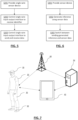
- FIG. 3 there is shown a schematic diagram of an example system 1 comprising a master device 20 connected to a plurality of slave devices 10 using a single-wire bidirectional line 11.
- the plurality of slave devices 10 are sensor devices 10 as per the example sensor device 10 shown in Figure 1 .
- Each of the sensor devices 10 may comprise the same type of sensor module 101 or may comprise different types of sensor module 101 for sensing different types of data.
- Additional slave devices having different configurations to the sensor device 10 of Figure 1 may also be connected to the single-wire bidirectional line 11.
- the plurality of sensor devices 10 and the master device 20 also have a ground line 13 for connecting the sensor devices 10 and master device 20 to ground 15. No other wired connections between the master device 20 and the sensor devices 10 are provided.
- the master device 20 initiates the sensor devices 10 and controls the transmission of data over the single-wire bidirectional line 11.
- the master device 20 is arranged to transmit data to the sensor devices 10 and receive data from the sensor devices 10 over the single-wire bidirectional line 11. Power may also be transferred to the sensor devices 10 over the single-wire bidirectional line 11.
- the master device 20 first transmits a "reset" command to the sensor devices 10 which synchronises all of the devices connected to the single-wire bidirectional line 11.
- the master device 20 then transmits a selection command comprising an identifier for one of the sensor devices 10 to the sensor devices 10 over the single-wire bidirectional line 11.
- the sensor device 10 with the corresponding identifier stored in the memory of the sensor device 10 is selected while the other sensor devices 10 configure themselves to ignore subsequent communications over the single-wire bidirectional line 11 until the next "reset" command is transmitted by the master device 20 over the single-wire bidirectional line 11.
- the master device 20 is able to transmit commands to the sensor device 10 as well as data to the sensor device 10.
- the master device 20 is also able to read data from the sensor device 10.
- the master device 20 may read data from the buffer of the sensor device 10. This enables the master device 20 to read time-series data from the buffer of the sensor device 10.
- the master device 20 may write data to the memory of the sensor device 10.
- the data written to the memory of the sensor device 10 may be a new or updated identifier for the sensor device 10.
- the master device 20 may transmit a command to the sensor device 10.
- the command may be for changing the type of data sensed by the sensor device 10 or the type of data output by the sensor device 10 over the single-wire bidirectional line 11.
- the master device 20 may be desirable to provide data to the master device 20 in real-time or near real time.
- the master device 20 is able to transmit a request for recent data sensed by the sensor device 10, and the sensor device 10 transmits the recent data as a result. Meanwhile, the sensor device 10 may still retain data locally on the buffer. Once the master device 20 no longer requires real-time or near-real time data, the master device 20 may read out the original high resolution time-series sensor data from the buffer of the sensor device 10. This approach enables the master device 20 to obtain low-resolution data or data at a low sampling rate for real-time processing operations while still maintaining the original high-resolution/high sampling rate data for later retrieval and analysis.
- the master device 20 may be a removable electronic module for the wearable article.
- the electronic module may be configured to be releasably mechanically coupled to the wearable article.
- the mechanical coupling of the electronic module to the wearable article may be provided by a mechanical interface such as a clip, a plug and socket arrangement, etc.
- the mechanical coupling or mechanical interface may be configured to maintain the electronic module in a particular orientation with respect to the garment when the electronic module is coupled to the wearable article. This may be beneficial in ensuring that the electronic module is securely held in place with respect to the garment and/or that any electronic coupling of the electronic module and the wearable article (or a component of the garment) can be optimized.
- the mechanical coupling may be maintained using friction or using a positively engaging mechanism, for example.
- the master device 20 may comprise a communicator.
- the communicator may be a mobile/cellular communicator operable to communicate the data wirelessly via one or more base stations.
- the communicator may provide wireless communication capabilities for the garment and enables the garment to communicate via one or more wireless communication protocols such as used for communication on: a wireless wide area network (WWAN), a wireless metroarea network (WMAN), a wireless local area network (WLAN), a wireless personal area network (WPAN), a near field communication (NFC), and a cellular communication network.
- the cellular communication network may be a fourth generation (4G) LTE, LTE Advanced (LTE-A), fifth generation (5G), sixth generation (6G), and/or any other present or future developed cellular wireless network.
- a first communicator of the master device 20 may be provided for cellular communication and a separate communicator may be provided for short-range local communication over WLAN, WPAN, NFC, or Bluetooth ® , WiFi or any other electromagnetic RF communication protocol.
- the master device 20 may comprise a Universal Integrated Circuit Card (UICC) that enables the wearable article to access services provided by a mobile network operator (MNO).
- the UICC may include at least a read-only memory (ROM) configured to store an MNO profile that the wearable article can utilize to register and interact with an MNO.
- the UICC may be in the form of a Subscriber Identity Module (SIM) card.
- SIM Subscriber Identity Module
- the wearable article may have a receiving section arranged to receive the SIM card.
- the UICC is embedded directly into a controller of the wearable article. That is, the UICC may be an electronic/embedded UICC (eUICC).
- eUICC is beneficial as it removes the need to store a number of MNO profiles, i.e. electronic Subscriber Identity Modules (eSIMs).
- eSIMs can be remotely provisioned to garments.
- the wearable article may comprise a secure element that represents an embedded Universal Integrated Circuit Card (eUICC).
Landscapes
- Engineering & Computer Science (AREA)
- Physics & Mathematics (AREA)
- General Physics & Mathematics (AREA)
- Computer Networks & Wireless Communication (AREA)
- Signal Processing (AREA)
- Computing Systems (AREA)
- Computer Security & Cryptography (AREA)
- Health & Medical Sciences (AREA)
- General Health & Medical Sciences (AREA)
- Medical Informatics (AREA)
- Arrangements For Transmission Of Measured Signals (AREA)
Claims (13)
- Wearable-Artikel (30), der eine Sensorvorrichtung (10) umfasst, wobei die Sensorvorrichtung (10) Folgendes umfasst:ein Sensormodul (101);einen Puffer (103), der dazu ausgelegt ist, Zeitreihen-Sensordaten zu speichern, die durch das Sensormodul (101) erfasst werden; undeine Eingabe-Ausgabe-Schnittstelle (105), die dazu ausgelegt ist, Daten über eine bidirektionale Leitung zu senden und zu empfangen; unddadurch gekennzeichnet, dass die Sensorvorrichtung (10) ferner einen programmierbaren nichtflüchtigen Speicher (109) umfasst, der dazu ausgelegt ist, eine Kennung für die Sensorvorrichtung zu speichern,wobei der Speicher (109) ein löschbarer und umprogrammierbarer nichtflüchtiger Speicher (109) ist,und wobei die Eingabe-Ausgabe-Schnittstelle (105) dazu ausgelegt ist, eine Kennung über die bidirektionale Leitung zu empfangen und die Kennung als die Kennung für die Sensorvorrichtung (10) in den löschbaren und programmierbaren Speicher zu schreiben.
- Wearable-Artikel (30) nach Anspruch 1, wobei die Eingabe-Ausgabe-Schnittstelle (105) dazu ausgelegt ist, die Zeitreihen-Sensordaten über die bidirektionale Leitung zu senden.
- Wearable-Artikel (30) nach Anspruch 1 oder 2, wobei die Eingabe-Ausgabe-Schnittstelle (105) eine Ein-Draht-Eingabe-Ausgabe-Schnittstelle ist.
- Wearable-Artikel (30) nach einem der vorhergehenden Ansprüche, wobei die Sensorvorrichtung (10) dazu ausgelegt ist, Leistung über die Eingabe-Ausgabe-Schnittstelle (105) zu empfangen.
- Wearable-Artikel (30) nach einem der vorhergehenden Ansprüche, wobei die Sensorvorrichtung (10) ferner eine Leistungsquelle (107) umfasst, die dazu ausgelegt ist, der Sensorvorrichtung (10) Leistung zuzuführen.
- Wearable-Artikel (30) nach Anspruch 5, wobei die Sensorvorrichtung (10) dazu ausgelegt ist, Leistung über die Eingabe-Ausgabe-Schnittstelle (105) zu empfangen und die Leistung in der Leistungsquelle (107) zu speichern.
- Wearable-Artikel (30) nach Anspruch 5 oder 6, wobei die Leistungsquelle (107) einen Kondensator, optional einen Superkondensator, umfasst.
- Wearable-Artikel (30) nach Anspruch 5 oder 6, wobei die Leistungsquelle (107) eine wiederaufladbare Batterie umfasst.
- Wearable-Artikel (30) nach einem der vorhergehenden Ansprüche, wobei die Eingabe-Ausgabe-Schnittstelle (105) dazu ausgelegt ist, eine Kennung über die bidirektionale Leitung zu empfangen, und wobei die Sensorvorrichtung (10) dazu ausgelegt ist, die empfangene Kennung mit der Kennung für die Sensorvorrichtung (10) zu vergleichen, die in dem nichtflüchtigen Speicher gespeichert ist.
- Wearable-Artikel (30) nach einem der vorhergehenden Ansprüche, wobei das Sensormodul (101) einen Prozessor (113) und einen Speicher (115) umfasst, wobei der Speicher (115) Anweisungen speichert und wobei die Anweisungen bei Ausführung durch den Prozessor (113) bewirken, dass der Prozessor (113) Operationen durchführt, wobei die Operationen Erzeugen einer komprimierten Repräsentation von Daten, die durch das Sensormodul erfasst werden, umfassen, wobei die komprimierte Repräsentation optional eine Inferenz umfasst, die aus durch das Sensormodul (101) erfassten Daten erzeugt wird.
- Wearable-Artikel (30) nach Anspruch 10, wobei die Eingabe-Ausgabe-Schnittstelle (105) dazu ausgelegt ist, die komprimierte Repräsentation der durch das Sensormodul (101) erfassten Daten über die bidirektionale Linie zu senden.
- Wearable-Artikel (30) nach Anspruch 10 oder 11, wobei die Sensorvorrichtung (10) dazu ausgelegt ist, zwischen dem Senden, über die bidirektionale Leitung, der durch das Sensormodul (101) erfassten Zeitreihendaten und der komprimierten Repräsentation von durch das Sensormodul (101) erfassten Daten umzuschalten.
- Wearable-Artikel (30) nach einem der vorhergehenden Ansprüche, der ferner Folgendes umfasst:eine Master-Vorrichtung (20); undwobei die Sensorvorrichtung (10) mehrere Sensorvorrichtungen (10) umfasst, wobei die mehreren Sensorvorrichtungen (10) und die Master-Vorrichtung (20) über eine bidirektionale Leitung miteinander verbunden sind und wobei Daten zwischen der Master-Vorrichtung (20) und den mehreren Sensorvorrichtungen (10) über die bidirektionale Leitung ausgetauscht werden können, wobei optional die Master-Vorrichtung (20) lösbar mit dem Wearable-Artikel (30) gekoppelt ist.
Priority Applications (1)
| Application Number | Priority Date | Filing Date | Title |
|---|---|---|---|
| EP25179882.3A EP4636363A2 (de) | 2019-11-28 | 2020-11-26 | Tragbarer artikel mit einer sensorvorrichtung |
Applications Claiming Priority (2)
| Application Number | Priority Date | Filing Date | Title |
|---|---|---|---|
| GB1917332.7A GB2589359A (en) | 2019-11-28 | 2019-11-28 | Sensor device, system and wearable article |
| PCT/GB2020/053006 WO2021105677A1 (en) | 2019-11-28 | 2020-11-26 | Wearable article comprising a sensor device |
Related Child Applications (2)
| Application Number | Title | Priority Date | Filing Date |
|---|---|---|---|
| EP25179882.3A Division EP4636363A2 (de) | 2019-11-28 | 2020-11-26 | Tragbarer artikel mit einer sensorvorrichtung |
| EP25179882.3A Division-Into EP4636363A2 (de) | 2019-11-28 | 2020-11-26 | Tragbarer artikel mit einer sensorvorrichtung |
Publications (3)
| Publication Number | Publication Date |
|---|---|
| EP4051990A1 EP4051990A1 (de) | 2022-09-07 |
| EP4051990C0 EP4051990C0 (de) | 2025-07-09 |
| EP4051990B1 true EP4051990B1 (de) | 2025-07-09 |
Family
ID=69147202
Family Applications (2)
| Application Number | Title | Priority Date | Filing Date |
|---|---|---|---|
| EP25179882.3A Pending EP4636363A2 (de) | 2019-11-28 | 2020-11-26 | Tragbarer artikel mit einer sensorvorrichtung |
| EP20816574.6A Active EP4051990B1 (de) | 2019-11-28 | 2020-11-26 | Tragbarer artikel mit einer sensorvorrichtung |
Family Applications Before (1)
| Application Number | Title | Priority Date | Filing Date |
|---|---|---|---|
| EP25179882.3A Pending EP4636363A2 (de) | 2019-11-28 | 2020-11-26 | Tragbarer artikel mit einer sensorvorrichtung |
Country Status (4)
| Country | Link |
|---|---|
| US (1) | US12131629B2 (de) |
| EP (2) | EP4636363A2 (de) |
| GB (1) | GB2589359A (de) |
| WO (1) | WO2021105677A1 (de) |
Family Cites Families (44)
| Publication number | Priority date | Publication date | Assignee | Title |
|---|---|---|---|---|
| DE19647668A1 (de) | 1996-11-19 | 1998-05-28 | Bosch Gmbh Robert | Slavestation, Masterstation, BUS-System und Verfahren zum Betreiben eines BUS-Systems |
| US20030023777A1 (en) | 2001-07-27 | 2003-01-30 | Ken Fields | Dynamic address assignment for one-wire interface |
| US7144830B2 (en) | 2002-05-10 | 2006-12-05 | Sarnoff Corporation | Plural layer woven electronic textile, article and method |
| US6646336B1 (en) | 2002-06-28 | 2003-11-11 | Koninkl Philips Electronics Nv | Wearable silicon chip |
| DE10251900A1 (de) | 2002-11-07 | 2004-05-19 | Trium Analysis Online GmbH c/o Institut für Medizinische Statistik und Epidemiologie (IMSE) der TU München Klinikum rechts der Isar | Patientenüberwachungssystem und -verfahren |
| DE10354602A1 (de) * | 2003-11-21 | 2005-06-16 | Robert Bosch Gmbh | Verbindungselemente, Verfahren zur Buskommunikation zwischen einem Steuergerät zur Ansteuerung von Personenschutzmitteln als Master und wenigstens einem Verbindungselement zur Gewichtsmessung in einem Sitz als Slave und Bus-System |
| US7880282B2 (en) | 2003-12-18 | 2011-02-01 | Rf Module & Optical Design Ltd. | Semiconductor package with integrated heatsink and electromagnetic shield |
| US6943061B1 (en) | 2004-04-12 | 2005-09-13 | Ns Electronics Bangkok (1993) Ltd. | Method of fabricating semiconductor chip package using screen printing of epoxy on wafer |
| US8022522B1 (en) | 2005-04-01 | 2011-09-20 | Marvell International Ltd. | Semiconductor package |
| US7760082B2 (en) * | 2005-09-21 | 2010-07-20 | Chon Meng Wong | System and method for active monitoring and diagnostics of life signs using heartbeat waveform and body temperature remotely giving the user freedom to move within its vicinity without wires attachment, gel, or adhesives |
| EP1818672B1 (de) | 2006-02-14 | 2012-08-29 | Mettler-Toledo AG | Messvorrichtung und Verfahren für den Betrieb der Messvorrichtung |
| US20100036209A1 (en) | 2008-08-07 | 2010-02-11 | Searete Llc, A Limited Liability Corporation Of The State Of Delaware | Circulatory monitoring systems and methods |
| CH702634A1 (de) | 2010-02-04 | 2011-08-15 | Radicos Technologies Gmbh | Adressierbare knoteneinheit und verfahren zum adressieren. |
| US9282893B2 (en) | 2012-09-11 | 2016-03-15 | L.I.F.E. Corporation S.A. | Wearable communication platform |
| US9498128B2 (en) | 2012-11-14 | 2016-11-22 | MAD Apparel, Inc. | Wearable architecture and methods for performance monitoring, analysis, and feedback |
| US20140269812A1 (en) * | 2013-03-14 | 2014-09-18 | Primex Wireless, Inc | Method and Apparatus for Probe Calibration |
| US9658296B2 (en) | 2013-07-10 | 2017-05-23 | Infineon Technologies Ag | Current sensor device |
| US9138191B1 (en) | 2014-07-09 | 2015-09-22 | Qualcomm Incorporated | Integrated circuit module with lead frame micro-needles |
| AU2015323905A1 (en) | 2014-09-29 | 2017-04-27 | MAD Apparel, Inc. | Garment integrated electrical interface system and method of manufacture |
| US20170319132A1 (en) | 2014-10-01 | 2017-11-09 | L.I.F.E. Corporation S.A. | Devices and methods for use with physiological monitoring garments |
| EP3258845B1 (de) | 2015-02-19 | 2025-07-30 | 6Degrees Ltd. | Ferngesteuerte physische aktivitätsüberwachung |
| WO2016181958A1 (ja) | 2015-05-11 | 2016-11-17 | 学校法人早稲田大学 | 電子デバイスおよびその製造方法 |
| CN106469699A (zh) | 2015-08-21 | 2017-03-01 | 意法半导体有限公司 | 半导体装置及其制造方法 |
| DE112015006957T5 (de) | 2015-09-24 | 2018-06-07 | Intel Corporation | Dehnbare elektronische Anordnung |
| WO2017117048A1 (en) | 2015-12-29 | 2017-07-06 | Zoll Medical Corporation | Monitoring a garment |
| US20170264978A1 (en) | 2016-03-10 | 2017-09-14 | Sentrix Technology Limited | Wearable electronic module and attachment system |
| JP2019524204A (ja) | 2016-07-01 | 2019-09-05 | エル.アイ.エフ.イー. コーポレーション エス.エー.L.I.F.E. Corporation S.A. | 複数のセンサを有する衣服によるバイオメトリクス識別 |
| US10149645B2 (en) | 2016-07-12 | 2018-12-11 | Andrew Poutiatine | System for tracking and responding to solar radiation exposure for improvement of athletic performance |
| KR20180032985A (ko) | 2016-09-23 | 2018-04-02 | 삼성전자주식회사 | 집적회로 패키지 및 그 제조 방법과 집적회로 패키지를 포함하는 웨어러블 디바이스 |
| GB2555592B (en) | 2016-11-02 | 2019-02-27 | Conductive Transfers Ltd | Transfer for application to a surface |
| US10530083B2 (en) | 2016-11-16 | 2020-01-07 | Honeywell Safety Products Usa, Inc. | Printed circuit board biosensing garment connector |
| DE102017012056A1 (de) | 2016-12-30 | 2018-07-05 | Suunto Oy | Tragbares kleidungsstück sowie system und verfahren zum bestimmen der durch ein tragbares kleidungsstück bereitgestellten stützung |
| EP3370367A1 (de) * | 2017-03-03 | 2018-09-05 | Iristick nv | System mit einem kopfhörer und einer kommunikationseinheit |
| GB201804502D0 (en) | 2018-03-21 | 2018-05-02 | Smith & Nephew | Biocompatible encapsulation and component stress relief for sensor enabled negative pressure wound therapy dressings |
| EP3493479B1 (de) | 2017-11-30 | 2020-12-02 | Elmos Semiconductor SE | Verfahren zum einspeisen von adressierungsströmen durch busknoten eines seriellen datenbussystems und busknoten für ein derartiges datenbussystem |
| WO2019134031A2 (en) | 2018-01-06 | 2019-07-11 | Myant Inc. | Electronics-to-textile interconnection method and system |
| IT201800004357A1 (it) | 2018-04-10 | 2019-10-10 | Dispositivo elettronico elastico applicabile su tessuto | |
| US11534615B2 (en) * | 2018-04-26 | 2022-12-27 | West Affum Holdings Dac | Wearable Cardioverter Defibrillator (WCD) system logging events and broadcasting state changes and system status information to external clients |
| CN110123305A (zh) | 2019-04-13 | 2019-08-16 | 复旦大学 | 一种跨层优化的可穿戴心电采集系统 |
| GB2593674B (en) | 2020-03-24 | 2025-05-14 | Prevayl Innovations Ltd | Layer structure comprising a semiconductor package |
| US12288736B2 (en) | 2019-11-28 | 2025-04-29 | Prevayl Innovations Limited | Sensor package, article comprising the same and manufacturing method thereof |
| GB2589567B (en) | 2019-11-28 | 2024-07-10 | Prevayl Innovations Ltd | Semiconductor package, article and method |
| GB2593479B (en) | 2020-03-24 | 2024-04-03 | Prevayl Innovations Ltd | Article with semiconductor package and method |
| GB2592391B (en) | 2020-02-26 | 2022-11-16 | Prevayl Innovations Ltd | Signal measuring apparatus and system |
-
2019
- 2019-11-28 GB GB1917332.7A patent/GB2589359A/en not_active Withdrawn
-
2020
- 2020-11-26 WO PCT/GB2020/053006 patent/WO2021105677A1/en not_active Ceased
- 2020-11-26 EP EP25179882.3A patent/EP4636363A2/de active Pending
- 2020-11-26 US US17/779,486 patent/US12131629B2/en active Active
- 2020-11-26 EP EP20816574.6A patent/EP4051990B1/de active Active
Also Published As
| Publication number | Publication date |
|---|---|
| WO2021105677A1 (en) | 2021-06-03 |
| EP4051990A1 (de) | 2022-09-07 |
| US20230020184A1 (en) | 2023-01-19 |
| EP4051990C0 (de) | 2025-07-09 |
| EP4636363A2 (de) | 2025-10-22 |
| GB201917332D0 (en) | 2020-01-15 |
| GB2589359A (en) | 2021-06-02 |
| US12131629B2 (en) | 2024-10-29 |
Similar Documents
| Publication | Publication Date | Title |
|---|---|---|
| US12543043B2 (en) | Electronics module for a wearable article | |
| US12130686B2 (en) | Electronics module for a wearable device | |
| US11813080B2 (en) | Sensor device, method and wearable article | |
| WO2021105684A1 (en) | Wearable article, electronic module, system and method | |
| EP4051990B1 (de) | Tragbarer artikel mit einer sensorvorrichtung | |
| GB2589360A (en) | Sensor device, system and wearable article | |
| US20230014669A1 (en) | Wearable article, electronic module, system and method | |
| WO2021105681A1 (en) | Sensor device, system and wearable article | |
| WO2021105682A1 (en) | Wearable article and method of making the same | |
| GB2591726A (en) | Sensor device, system and wearable article | |
| GB2590896A (en) | Sensor device, system and wearable device | |
| GB2585729A (en) | Electronics module for a wearable article | |
| GB2592900A (en) | Electronics module for a wearable article | |
| GB2599673A (en) | Method and system for measuring and displaying biosignal data to a wearer of a wearable article | |
| US20260129454A1 (en) | Electronics Module for a Wearable Article | |
| US12376061B2 (en) | Wearable device and method | |
| US20220240855A1 (en) | Wearable device and method | |
| GB2596932A (en) | Electronics module for a wearable article | |
| GB2613249A (en) | Method, system and article | |
| WO2023105201A1 (en) | Electronics module, a controller for an electronics module and a method performed by a controller | |
| GB2585728A (en) | Electronics module for a wearable article | |
| GB2611457A (en) | Electronics module for a wearable article | |
| GB2611459A (en) | Electronics module for a wearable article | |
| WO2021105679A1 (en) | Wearable article, electronic module, system and method | |
| GB2644367A (en) | System comprising a garment hanger with means to retain an electronics module |
Legal Events
| Date | Code | Title | Description |
|---|---|---|---|
| STAA | Information on the status of an ep patent application or granted ep patent |
Free format text: STATUS: UNKNOWN |
|
| STAA | Information on the status of an ep patent application or granted ep patent |
Free format text: STATUS: THE INTERNATIONAL PUBLICATION HAS BEEN MADE |
|
| PUAI | Public reference made under article 153(3) epc to a published international application that has entered the european phase |
Free format text: ORIGINAL CODE: 0009012 |
|
| STAA | Information on the status of an ep patent application or granted ep patent |
Free format text: STATUS: REQUEST FOR EXAMINATION WAS MADE |
|
| 17P | Request for examination filed |
Effective date: 20220601 |
|
| AK | Designated contracting states |
Kind code of ref document: A1 Designated state(s): AL AT BE BG CH CY CZ DE DK EE ES FI FR GB GR HR HU IE IS IT LI LT LU LV MC MK MT NL NO PL PT RO RS SE SI SK SM TR |
|
| DAV | Request for validation of the european patent (deleted) | ||
| DAX | Request for extension of the european patent (deleted) | ||
| STAA | Information on the status of an ep patent application or granted ep patent |
Free format text: STATUS: EXAMINATION IS IN PROGRESS |
|
| 17Q | First examination report despatched |
Effective date: 20231004 |
|
| RAP3 | Party data changed (applicant data changed or rights of an application transferred) |
Owner name: PREVAYL INNOVATIONS LIMITED |
|
| RAP3 | Party data changed (applicant data changed or rights of an application transferred) |
Owner name: PREVAYL INNOVATIONS LIMITED |
|
| RAP3 | Party data changed (applicant data changed or rights of an application transferred) |
Owner name: PREVAYL INNOVATIONS LIMITED |
|
| GRAP | Despatch of communication of intention to grant a patent |
Free format text: ORIGINAL CODE: EPIDOSNIGR1 |
|
| STAA | Information on the status of an ep patent application or granted ep patent |
Free format text: STATUS: GRANT OF PATENT IS INTENDED |
|
| INTG | Intention to grant announced |
Effective date: 20250205 |
|
| GRAS | Grant fee paid |
Free format text: ORIGINAL CODE: EPIDOSNIGR3 |
|
| GRAA | (expected) grant |
Free format text: ORIGINAL CODE: 0009210 |
|
| STAA | Information on the status of an ep patent application or granted ep patent |
Free format text: STATUS: THE PATENT HAS BEEN GRANTED |
|
| AK | Designated contracting states |
Kind code of ref document: B1 Designated state(s): AL AT BE BG CH CY CZ DE DK EE ES FI FR GB GR HR HU IE IS IT LI LT LU LV MC MK MT NL NO PL PT RO RS SE SI SK SM TR |
|
| REG | Reference to a national code |
Ref country code: GB Ref legal event code: FG4D |
|
| REG | Reference to a national code |
Ref country code: CH Ref legal event code: EP |
|
| REG | Reference to a national code |
Ref country code: IE Ref legal event code: FG4D |
|
| REG | Reference to a national code |
Ref country code: DE Ref legal event code: R096 Ref document number: 602020054291 Country of ref document: DE |
|
| U01 | Request for unitary effect filed |
Effective date: 20250807 |
|
| U07 | Unitary effect registered |
Designated state(s): AT BE BG DE DK EE FI FR IT LT LU LV MT NL PT RO SE SI Effective date: 20250819 |
|
| PG25 | Lapsed in a contracting state [announced via postgrant information from national office to epo] |
Ref country code: IS Free format text: LAPSE BECAUSE OF FAILURE TO SUBMIT A TRANSLATION OF THE DESCRIPTION OR TO PAY THE FEE WITHIN THE PRESCRIBED TIME-LIMIT Effective date: 20251109 |
|
| PGFP | Annual fee paid to national office [announced via postgrant information from national office to epo] |
Ref country code: GB Payment date: 20251229 Year of fee payment: 6 |
|
| PG25 | Lapsed in a contracting state [announced via postgrant information from national office to epo] |
Ref country code: NO Free format text: LAPSE BECAUSE OF FAILURE TO SUBMIT A TRANSLATION OF THE DESCRIPTION OR TO PAY THE FEE WITHIN THE PRESCRIBED TIME-LIMIT Effective date: 20251009 |
|
| PG25 | Lapsed in a contracting state [announced via postgrant information from national office to epo] |
Ref country code: HR Free format text: LAPSE BECAUSE OF FAILURE TO SUBMIT A TRANSLATION OF THE DESCRIPTION OR TO PAY THE FEE WITHIN THE PRESCRIBED TIME-LIMIT Effective date: 20250709 |
|
| PG25 | Lapsed in a contracting state [announced via postgrant information from national office to epo] |
Ref country code: GR Free format text: LAPSE BECAUSE OF FAILURE TO SUBMIT A TRANSLATION OF THE DESCRIPTION OR TO PAY THE FEE WITHIN THE PRESCRIBED TIME-LIMIT Effective date: 20251010 |
|
| PG25 | Lapsed in a contracting state [announced via postgrant information from national office to epo] |
Ref country code: PL Free format text: LAPSE BECAUSE OF FAILURE TO SUBMIT A TRANSLATION OF THE DESCRIPTION OR TO PAY THE FEE WITHIN THE PRESCRIBED TIME-LIMIT Effective date: 20250709 |
|
| PG25 | Lapsed in a contracting state [announced via postgrant information from national office to epo] |
Ref country code: RS Free format text: LAPSE BECAUSE OF FAILURE TO SUBMIT A TRANSLATION OF THE DESCRIPTION OR TO PAY THE FEE WITHIN THE PRESCRIBED TIME-LIMIT Effective date: 20251009 |
|
| PG25 | Lapsed in a contracting state [announced via postgrant information from national office to epo] |
Ref country code: ES Free format text: LAPSE BECAUSE OF FAILURE TO SUBMIT A TRANSLATION OF THE DESCRIPTION OR TO PAY THE FEE WITHIN THE PRESCRIBED TIME-LIMIT Effective date: 20250709 |
|
| PG25 | Lapsed in a contracting state [announced via postgrant information from national office to epo] |
Ref country code: SM Free format text: LAPSE BECAUSE OF FAILURE TO SUBMIT A TRANSLATION OF THE DESCRIPTION OR TO PAY THE FEE WITHIN THE PRESCRIBED TIME-LIMIT Effective date: 20250709 |
|
| PG25 | Lapsed in a contracting state [announced via postgrant information from national office to epo] |
Ref country code: CZ Free format text: LAPSE BECAUSE OF FAILURE TO SUBMIT A TRANSLATION OF THE DESCRIPTION OR TO PAY THE FEE WITHIN THE PRESCRIBED TIME-LIMIT Effective date: 20250709 |
|
| PG25 | Lapsed in a contracting state [announced via postgrant information from national office to epo] |
Ref country code: SK Free format text: LAPSE BECAUSE OF FAILURE TO SUBMIT A TRANSLATION OF THE DESCRIPTION OR TO PAY THE FEE WITHIN THE PRESCRIBED TIME-LIMIT Effective date: 20250709 |