EP4052018B1 - Chambre de réaction microfluidique dotée d'un circuit de chambre de réaction et procédé - Google Patents
Chambre de réaction microfluidique dotée d'un circuit de chambre de réaction et procédé Download PDFInfo
- Publication number
- EP4052018B1 EP4052018B1 EP20915018.4A EP20915018A EP4052018B1 EP 4052018 B1 EP4052018 B1 EP 4052018B1 EP 20915018 A EP20915018 A EP 20915018A EP 4052018 B1 EP4052018 B1 EP 4052018B1
- Authority
- EP
- European Patent Office
- Prior art keywords
- reaction chamber
- substrate
- microfluidic
- fluid
- circuit
- Prior art date
- Legal status (The legal status is an assumption and is not a legal conclusion. Google has not performed a legal analysis and makes no representation as to the accuracy of the status listed.)
- Active
Links
Images








Classifications
-
- B—PERFORMING OPERATIONS; TRANSPORTING
- B01—PHYSICAL OR CHEMICAL PROCESSES OR APPARATUS IN GENERAL
- B01L—CHEMICAL OR PHYSICAL LABORATORY APPARATUS FOR GENERAL USE
- B01L3/00—Containers or dishes for laboratory use, e.g. laboratory glassware; Droppers
- B01L3/50—Containers for the purpose of retaining a material to be analysed, e.g. test tubes
- B01L3/502—Containers for the purpose of retaining a material to be analysed, e.g. test tubes with fluid transport, e.g. in multi-compartment structures
- B01L3/5027—Containers for the purpose of retaining a material to be analysed, e.g. test tubes with fluid transport, e.g. in multi-compartment structures by integrated microfluidic structures, i.e. dimensions of channels and chambers are such that surface tension forces are important, e.g. lab-on-a-chip
- B01L3/502715—Containers for the purpose of retaining a material to be analysed, e.g. test tubes with fluid transport, e.g. in multi-compartment structures by integrated microfluidic structures, i.e. dimensions of channels and chambers are such that surface tension forces are important, e.g. lab-on-a-chip characterised by interfacing components, e.g. fluidic, electrical, optical or mechanical interfaces
-
- G—PHYSICS
- G01—MEASURING; TESTING
- G01N—INVESTIGATING OR ANALYSING MATERIALS BY DETERMINING THEIR CHEMICAL OR PHYSICAL PROPERTIES
- G01N21/00—Investigating or analysing materials by the use of optical means, i.e. using sub-millimetre waves, infrared, visible or ultraviolet light
- G01N21/62—Systems in which the material investigated is excited whereby it emits light or causes a change in wavelength of the incident light
- G01N21/63—Systems in which the material investigated is excited whereby it emits light or causes a change in wavelength of the incident light optically excited
- G01N21/64—Fluorescence; Phosphorescence
- G01N21/645—Specially adapted constructive features of fluorimeters
-
- B—PERFORMING OPERATIONS; TRANSPORTING
- B01—PHYSICAL OR CHEMICAL PROCESSES OR APPARATUS IN GENERAL
- B01L—CHEMICAL OR PHYSICAL LABORATORY APPARATUS FOR GENERAL USE
- B01L3/00—Containers or dishes for laboratory use, e.g. laboratory glassware; Droppers
- B01L3/50—Containers for the purpose of retaining a material to be analysed, e.g. test tubes
- B01L3/502—Containers for the purpose of retaining a material to be analysed, e.g. test tubes with fluid transport, e.g. in multi-compartment structures
- B01L3/5027—Containers for the purpose of retaining a material to be analysed, e.g. test tubes with fluid transport, e.g. in multi-compartment structures by integrated microfluidic structures, i.e. dimensions of channels and chambers are such that surface tension forces are important, e.g. lab-on-a-chip
- B01L3/502707—Containers for the purpose of retaining a material to be analysed, e.g. test tubes with fluid transport, e.g. in multi-compartment structures by integrated microfluidic structures, i.e. dimensions of channels and chambers are such that surface tension forces are important, e.g. lab-on-a-chip characterised by the manufacture of the container or its components
-
- B—PERFORMING OPERATIONS; TRANSPORTING
- B01—PHYSICAL OR CHEMICAL PROCESSES OR APPARATUS IN GENERAL
- B01L—CHEMICAL OR PHYSICAL LABORATORY APPARATUS FOR GENERAL USE
- B01L7/00—Heating or cooling apparatus; Heat insulating devices
- B01L7/52—Heating or cooling apparatus; Heat insulating devices with provision for submitting samples to a predetermined sequence of different temperatures, e.g. for treating nucleic acid samples
-
- C—CHEMISTRY; METALLURGY
- C12—BIOCHEMISTRY; BEER; SPIRITS; WINE; VINEGAR; MICROBIOLOGY; ENZYMOLOGY; MUTATION OR GENETIC ENGINEERING
- C12Q—MEASURING OR TESTING PROCESSES INVOLVING ENZYMES, NUCLEIC ACIDS OR MICROORGANISMS; COMPOSITIONS OR TEST PAPERS THEREFOR; PROCESSES OF PREPARING SUCH COMPOSITIONS; CONDITION-RESPONSIVE CONTROL IN MICROBIOLOGICAL OR ENZYMOLOGICAL PROCESSES
- C12Q1/00—Measuring or testing processes involving enzymes, nucleic acids or microorganisms; Compositions therefor; Processes of preparing such compositions
- C12Q1/68—Measuring or testing processes involving enzymes, nucleic acids or microorganisms; Compositions therefor; Processes of preparing such compositions involving nucleic acids
- C12Q1/6844—Nucleic acid amplification reactions
-
- G—PHYSICS
- G01—MEASURING; TESTING
- G01N—INVESTIGATING OR ANALYSING MATERIALS BY DETERMINING THEIR CHEMICAL OR PHYSICAL PROPERTIES
- G01N21/00—Investigating or analysing materials by the use of optical means, i.e. using sub-millimetre waves, infrared, visible or ultraviolet light
- G01N21/62—Systems in which the material investigated is excited whereby it emits light or causes a change in wavelength of the incident light
- G01N21/63—Systems in which the material investigated is excited whereby it emits light or causes a change in wavelength of the incident light optically excited
- G01N21/64—Fluorescence; Phosphorescence
- G01N21/6428—Measuring fluorescence of fluorescent products of reactions or of fluorochrome labelled reactive substances, e.g. measuring quenching effects, using measuring "optrodes"
-
- B—PERFORMING OPERATIONS; TRANSPORTING
- B01—PHYSICAL OR CHEMICAL PROCESSES OR APPARATUS IN GENERAL
- B01L—CHEMICAL OR PHYSICAL LABORATORY APPARATUS FOR GENERAL USE
- B01L2200/00—Solutions for specific problems relating to chemical or physical laboratory apparatus
- B01L2200/14—Process control and prevention of errors
- B01L2200/143—Quality control, feedback systems
- B01L2200/147—Employing temperature sensors
-
- B—PERFORMING OPERATIONS; TRANSPORTING
- B01—PHYSICAL OR CHEMICAL PROCESSES OR APPARATUS IN GENERAL
- B01L—CHEMICAL OR PHYSICAL LABORATORY APPARATUS FOR GENERAL USE
- B01L2200/00—Solutions for specific problems relating to chemical or physical laboratory apparatus
- B01L2200/16—Reagents, handling or storing thereof
-
- B—PERFORMING OPERATIONS; TRANSPORTING
- B01—PHYSICAL OR CHEMICAL PROCESSES OR APPARATUS IN GENERAL
- B01L—CHEMICAL OR PHYSICAL LABORATORY APPARATUS FOR GENERAL USE
- B01L2300/00—Additional constructional details
- B01L2300/06—Auxiliary integrated devices, integrated components
- B01L2300/0627—Sensor or part of a sensor is integrated
- B01L2300/0645—Electrodes
-
- B—PERFORMING OPERATIONS; TRANSPORTING
- B01—PHYSICAL OR CHEMICAL PROCESSES OR APPARATUS IN GENERAL
- B01L—CHEMICAL OR PHYSICAL LABORATORY APPARATUS FOR GENERAL USE
- B01L2300/00—Additional constructional details
- B01L2300/06—Auxiliary integrated devices, integrated components
- B01L2300/0627—Sensor or part of a sensor is integrated
- B01L2300/0654—Lenses; Optical fibres
-
- B—PERFORMING OPERATIONS; TRANSPORTING
- B01—PHYSICAL OR CHEMICAL PROCESSES OR APPARATUS IN GENERAL
- B01L—CHEMICAL OR PHYSICAL LABORATORY APPARATUS FOR GENERAL USE
- B01L2300/00—Additional constructional details
- B01L2300/06—Auxiliary integrated devices, integrated components
- B01L2300/0627—Sensor or part of a sensor is integrated
- B01L2300/0663—Whole sensors
-
- B—PERFORMING OPERATIONS; TRANSPORTING
- B01—PHYSICAL OR CHEMICAL PROCESSES OR APPARATUS IN GENERAL
- B01L—CHEMICAL OR PHYSICAL LABORATORY APPARATUS FOR GENERAL USE
- B01L2300/00—Additional constructional details
- B01L2300/12—Specific details about materials
-
- B—PERFORMING OPERATIONS; TRANSPORTING
- B01—PHYSICAL OR CHEMICAL PROCESSES OR APPARATUS IN GENERAL
- B01L—CHEMICAL OR PHYSICAL LABORATORY APPARATUS FOR GENERAL USE
- B01L2300/00—Additional constructional details
- B01L2300/18—Means for temperature control
-
- B—PERFORMING OPERATIONS; TRANSPORTING
- B01—PHYSICAL OR CHEMICAL PROCESSES OR APPARATUS IN GENERAL
- B01L—CHEMICAL OR PHYSICAL LABORATORY APPARATUS FOR GENERAL USE
- B01L2300/00—Additional constructional details
- B01L2300/18—Means for temperature control
- B01L2300/1805—Conductive heating, heat from thermostatted solids is conducted to receptacles, e.g. heating plates, blocks
- B01L2300/1827—Conductive heating, heat from thermostatted solids is conducted to receptacles, e.g. heating plates, blocks using resistive heater
-
- G—PHYSICS
- G01—MEASURING; TESTING
- G01N—INVESTIGATING OR ANALYSING MATERIALS BY DETERMINING THEIR CHEMICAL OR PHYSICAL PROPERTIES
- G01N21/00—Investigating or analysing materials by the use of optical means, i.e. using sub-millimetre waves, infrared, visible or ultraviolet light
- G01N21/01—Arrangements or apparatus for facilitating the optical investigation
- G01N21/03—Cuvette constructions
- G01N2021/0325—Cells for testing reactions, e.g. containing reagents
-
- G—PHYSICS
- G01—MEASURING; TESTING
- G01N—INVESTIGATING OR ANALYSING MATERIALS BY DETERMINING THEIR CHEMICAL OR PHYSICAL PROPERTIES
- G01N21/00—Investigating or analysing materials by the use of optical means, i.e. using sub-millimetre waves, infrared, visible or ultraviolet light
- G01N21/01—Arrangements or apparatus for facilitating the optical investigation
- G01N21/03—Cuvette constructions
- G01N2021/0346—Capillary cells; Microcells
-
- G—PHYSICS
- G01—MEASURING; TESTING
- G01N—INVESTIGATING OR ANALYSING MATERIALS BY DETERMINING THEIR CHEMICAL OR PHYSICAL PROPERTIES
- G01N21/00—Investigating or analysing materials by the use of optical means, i.e. using sub-millimetre waves, infrared, visible or ultraviolet light
- G01N21/01—Arrangements or apparatus for facilitating the optical investigation
- G01N21/03—Cuvette constructions
- G01N21/05—Flow-through cuvettes
- G01N2021/058—Flat flow cell
-
- G—PHYSICS
- G01—MEASURING; TESTING
- G01N—INVESTIGATING OR ANALYSING MATERIALS BY DETERMINING THEIR CHEMICAL OR PHYSICAL PROPERTIES
- G01N21/00—Investigating or analysing materials by the use of optical means, i.e. using sub-millimetre waves, infrared, visible or ultraviolet light
- G01N21/62—Systems in which the material investigated is excited whereby it emits light or causes a change in wavelength of the incident light
- G01N21/63—Systems in which the material investigated is excited whereby it emits light or causes a change in wavelength of the incident light optically excited
- G01N21/64—Fluorescence; Phosphorescence
- G01N2021/6417—Spectrofluorimetric devices
- G01N2021/6419—Excitation at two or more wavelengths
-
- G—PHYSICS
- G01—MEASURING; TESTING
- G01N—INVESTIGATING OR ANALYSING MATERIALS BY DETERMINING THEIR CHEMICAL OR PHYSICAL PROPERTIES
- G01N21/00—Investigating or analysing materials by the use of optical means, i.e. using sub-millimetre waves, infrared, visible or ultraviolet light
- G01N21/62—Systems in which the material investigated is excited whereby it emits light or causes a change in wavelength of the incident light
- G01N21/63—Systems in which the material investigated is excited whereby it emits light or causes a change in wavelength of the incident light optically excited
- G01N21/64—Fluorescence; Phosphorescence
- G01N2021/6417—Spectrofluorimetric devices
- G01N2021/6421—Measuring at two or more wavelengths
-
- G—PHYSICS
- G01—MEASURING; TESTING
- G01N—INVESTIGATING OR ANALYSING MATERIALS BY DETERMINING THEIR CHEMICAL OR PHYSICAL PROPERTIES
- G01N21/00—Investigating or analysing materials by the use of optical means, i.e. using sub-millimetre waves, infrared, visible or ultraviolet light
- G01N21/62—Systems in which the material investigated is excited whereby it emits light or causes a change in wavelength of the incident light
- G01N21/63—Systems in which the material investigated is excited whereby it emits light or causes a change in wavelength of the incident light optically excited
- G01N21/64—Fluorescence; Phosphorescence
- G01N21/6428—Measuring fluorescence of fluorescent products of reactions or of fluorochrome labelled reactive substances, e.g. measuring quenching effects, using measuring "optrodes"
- G01N2021/6439—Measuring fluorescence of fluorescent products of reactions or of fluorochrome labelled reactive substances, e.g. measuring quenching effects, using measuring "optrodes" with indicators, stains, dyes, tags, labels, marks
-
- G—PHYSICS
- G01—MEASURING; TESTING
- G01N—INVESTIGATING OR ANALYSING MATERIALS BY DETERMINING THEIR CHEMICAL OR PHYSICAL PROPERTIES
- G01N21/00—Investigating or analysing materials by the use of optical means, i.e. using sub-millimetre waves, infrared, visible or ultraviolet light
- G01N21/62—Systems in which the material investigated is excited whereby it emits light or causes a change in wavelength of the incident light
- G01N21/63—Systems in which the material investigated is excited whereby it emits light or causes a change in wavelength of the incident light optically excited
- G01N21/64—Fluorescence; Phosphorescence
- G01N21/6428—Measuring fluorescence of fluorescent products of reactions or of fluorochrome labelled reactive substances, e.g. measuring quenching effects, using measuring "optrodes"
- G01N2021/6439—Measuring fluorescence of fluorescent products of reactions or of fluorochrome labelled reactive substances, e.g. measuring quenching effects, using measuring "optrodes" with indicators, stains, dyes, tags, labels, marks
- G01N2021/6441—Measuring fluorescence of fluorescent products of reactions or of fluorochrome labelled reactive substances, e.g. measuring quenching effects, using measuring "optrodes" with indicators, stains, dyes, tags, labels, marks with two or more labels
-
- G—PHYSICS
- G01—MEASURING; TESTING
- G01N—INVESTIGATING OR ANALYSING MATERIALS BY DETERMINING THEIR CHEMICAL OR PHYSICAL PROPERTIES
- G01N21/00—Investigating or analysing materials by the use of optical means, i.e. using sub-millimetre waves, infrared, visible or ultraviolet light
- G01N21/62—Systems in which the material investigated is excited whereby it emits light or causes a change in wavelength of the incident light
- G01N21/63—Systems in which the material investigated is excited whereby it emits light or causes a change in wavelength of the incident light optically excited
- G01N21/64—Fluorescence; Phosphorescence
- G01N21/645—Specially adapted constructive features of fluorimeters
- G01N2021/6482—Sample cells, cuvettes
-
- G—PHYSICS
- G01—MEASURING; TESTING
- G01N—INVESTIGATING OR ANALYSING MATERIALS BY DETERMINING THEIR CHEMICAL OR PHYSICAL PROPERTIES
- G01N21/00—Investigating or analysing materials by the use of optical means, i.e. using sub-millimetre waves, infrared, visible or ultraviolet light
- G01N21/01—Arrangements or apparatus for facilitating the optical investigation
- G01N21/03—Cuvette constructions
- G01N21/0332—Cuvette constructions with temperature control
Definitions
- the present disclosure relates to an apparatus comprising a microfluidic reaction chamber to contain a reaction fluid for amplification of nucleic acids, and a reaction chamber circuit disposed within the microfluidic reaction chamber.
- the present disclosure also relates to a method using the microfluidic reaction chamber.
- Microfluidics is a technology that applies across a variety of disciplines including engineering, physics, chemistry, microtechnology and biotechnology. Microfluidics involves the study of small volumes of fluid and how to manipulate, control and use such small volumes of fluid in various microfluidic systems and devices such as microfluidic chips.
- microfluidic biochips referred to as "lab-on-chip" are used in the field of molecular biology to integrate assay operations for purposes such as analyzing enzymes and nucleic acids, detecting biochemical toxins and pathogens, diagnosing diseases, etc.
- PCR Polymerase chain reaction
- US2008300146A1 discloses a bio-chip device with a sample compartment and a light sensitive element and a method for the detection of fluorescent particles within at least one sample compartment of a bio chip device.
- US2009013768A1 discloses a device for bioassays with an integrated detector.
- US2016356715A1 discloses biosensors for biological or chemical analysis and methods of manufacturing the same.
- US2019250102A1 discloses a fluorescent testing system, a molecular testing method, and a fluorescent testing method.
- WO2020222763A1 discloses a microfluidic reaction chamber for amplification of nucleic acids.
- the present invention is directed to an apparatus as defined in appended independent claim 1 and a method as defined in appended independent claim 10. Particular embodiments of the invention are defined in the appended dependent claims.
- PCR is a method used in molecular biology to make many copies of a nucleic acid segment. Using PCR, a single copy (or more) of a nucleic acid sequence is exponentially amplified to generate thousands to millions or more copies of that particular nucleic acid segment. PCR is a temperature-mediated process involving cycling a reaction volume, or mixture, between set temperatures. Many PCR methods utilize the visible range of fluorescent spectroscopy to detect nucleic acids. With fluorescent spectroscopy, a fluorescence signal is detected from a labeled fluorescent tag after washing the unconjugated tag. Upon excitation from an external light source, these fluorescent labels emit a signal. A transducer, such as a photodetector, can collect these signals and transduce them to the electrical domain (i.e., voltage or current) for signal amplification and conditioning.
- electrical domain i.e., voltage or current
- Detection mechanisms for fluorescent amplification utilize multiple devices.
- many fluorescence detection systems include an excitation light source, a fluorophore, wavelength filters to isolate emission photons from excitation photons, and a detector that registers emission photons and produces a recordable output, usually as an electrical signal.
- different respective optical filters may be used depending on the fluorescent markers used.
- the use of these multiple devices increases the cost and time of performing nucleic acid amplification and detection.
- difficulty may arise in orienting circuitry for heating reaction fluids, and detecting fluorescent signals, in such a position that high throughput PCR may be performed without local overheating of the reaction volume of the PCR device and without incorporating external devices.
- Fluorescent labels when attached directly to a probe molecule, allow for almost instantaneous detection. Fluorescence analysis is very sensitive, especially when special optical detection equipment is used. However, while sensitive optical detection equipment is available, it is rather expensive and thus out of reach for many researchers. Additionally, for each fluorescent probe used, when performing PCR or any other analytical technique involving microfluidic devices, a different respective light source and associated filter(s) may be used to detect the fluorescent signal.
- the present disclosure relates to an apparatus comprising a microfluidic reaction chamber to contain a reaction fluid for amplification of nucleic acids, and a reaction chamber circuit disposed within the microfluidic reaction chamber.
- the apparatus and method described herein may include the use of multiple filters and may therefore allow for multiple fluorescent probes to be used with a single handheld device. This reduces the use of multiple reaction chambers for multiple fluorescent probes (e.g., enabling multiplexing), and provides an integrated device for performing PCR and fluorescent detection. Moreover, the positioning of the reaction chamber circuit in the apparatus described herein, provides for high thermal efficiency, which permits the rapid and specific temperature changes for PCR to be achieved within the apparatus.
- the present disclosure relates to an apparatus comprising a microfluidic reaction chamber to contain a reaction fluid for amplification of nucleic acids, and a reaction chamber circuit disposed within the microfluidic reaction chamber.
- the microfluidic reaction chamber includes a base wall defined in part by a substrate, a top wall parallel to the base wall and defined in part by a transparent lid, a first side wall perpendicular to the base wall and defined in part by the transparent lid, and a second side wall perpendicular to the base wall and defined in part by the transparent lid.
- the reaction chamber circuit is disposed within the microfluidic reaction chamber, and includes a top surface parallel to and proximal to the top wall of the microfluidic reaction chamber, a bottom surface parallel to and distal to the top wall of the microfluidic reaction chamber, a first side wall parallel to the first side wall of the microfluidic reaction chamber, and a second side wall parallel to the second side wall of the microfluidic reaction chamber.
- the top surface of the reaction chamber circuit, the bottom surface of the reaction chamber circuit, the first side wall of the reaction chamber circuit and the second side wall of the reaction chamber circuit are in fluidic contact with the reaction fluid.
- the bottom surface of the reaction chamber circuit includes a photodetector to detect a fluorescence signal from a labeled fluorescent tag in the reaction fluid.
- the substrate includes a proximal end and a distal end opposite the proximal end, a first fluid channel traversing a width of the substrate, a second fluid channel traversing a width of the substrate, and a base wall disposed between the first fluid channel and the second fluid input/output.
- the transparent lid is coupled to the proximal end of the substrate and the distal end of the substrate to form a microfluidic reaction chamber.
- the reaction chamber circuit extends from the proximal end of the substrate to the distal end of the substrate and includes a top surface proximal to the transparent lid and a bottom surface distal to the transparent lid.
- the bottom surface of the reaction chamber circuit includes a photodetector to detect a fluorescence signal from a labeled fluorescent tag in a reaction fluid within the microfluidic reaction chamber.
- a method in yet another example, includes receiving a reaction fluid via a first fluid channel of a microfluidic reaction chamber, the reaction fluid including a reagent and a biologic sample for amplification of nucleic acids included in the biologic sample.
- the method includes containing the reaction fluid in the microfluidic reaction chamber such that a reaction chamber circuit suspended within the microfluidic reaction chamber is in direct fluidic contact with the reaction fluid.
- the method includes heating the reaction fluid to specified temperatures for nucleic acid amplification, and detecting a fluorescence signal from a labeled fluorescent tag in the reaction fluid indicative of amplification of the nucleic acids in the biologic sample, via a photodetector disposed on a bottom surface of the reaction chamber circuit and facing a base wall of the microfluidic reaction chamber.
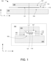
- Figure 1 is a schematic diagram of an example microfluidic reaction chamber with a reaction chamber circuit, according to the present disclosure.
- Figure 1 illustrates an apparatus 100 comprising a microfluidic reaction chamber 101 to contain a reaction fluid for amplification of nucleic acids.
- the microfluidic reaction chamber 101 may contain a small amount of reaction fluid, such as less than 10 ⁇ L of the reaction fluid.
- a reaction fluid refers to or includes a fluid including components to perform nucleic acid amplification with fluorescence detection.
- the components in the reaction fluid may include, a biologic sample that contains the target sequence(s) to be amplified, an enzyme that polymerizes new nucleic acid strands, two (or more) nucleic acid primers, deoxyribonucleotide triphosphates (dNTPs), a buffer solution providing a suitable chemical environment for amplification and optimum activity and stability of the polymerase, and a reporter molecule such as fluorophores.
- the polymerase enzyme include, but are not limited to, DNA polymerase such as Taq DNA polymerase, and reverse transcriptase.
- the buffer solution include components such as bivalent cations, including magnesium (Mg) or manganese (Mn) ions and monovalent cations, such as potassium (K) ions, among others.
- a reaction chamber circuit 115 is disposed within the microfluidic reaction chamber 101.
- a reaction chamber circuit refers to or includes circuitry to sense and measure properties of components of the reaction fluid in the microfluidic reaction chamber 101.
- the reaction chamber circuit 115 includes a complimentary metal-oxide-semiconductor (CMOS) silicon circuit. Examples are not so limited, however, and in various examples the reaction chamber circuit 115 may include an n-type transistor, a p-type transistor, and/or a metal-oxide-semiconductor field-effect transistor (MOSFET), among others.
- CMOS complimentary metal-oxide-semiconductor
- the presence of a transistor type circuit in a microfluidic reaction chamber provides the ability to sense and measure properties of components of the fluid in the chamber.
- the reaction chamber circuit 115 can also be used to heat reaction fluid in the reaction chamber.
- the reaction fluid may be in contact with the reaction chamber circuit in order to sense and measure properties of components in the fluid and heat the fluid in the reaction chamber.
- the microfluidic reaction chamber 101 is defined by several components.
- the microfluidic reactor includes a base wall 103 defined in part by a substrate 105, and a top wall 107 parallel to the base wall 103 and defined in part by a transparent lid 109.
- a cross-section 102 of apparatus 100 along the Y axis further illustrates positioning of various components of apparatus 100.
- the microfluidic reaction chamber 101 is further defined by a first side wall 111 perpendicular to the base wall 103 and defined in part by the transparent lid 109, and a second side wall 113 perpendicular to the base wall 103 and defined in part by the transparent lid 109.
- the transparent lid 109 therefore partially forms or makes up the microfluidic reaction chamber 101 and may be mounted on or attached to the substrate 105.
- the transparent lid 109 may comprise glass, quartz, poly (methyl methacrylate), polycarbonates, cyclic olefin copolymer, polyethylene terephthalate, polyethylene terephthalate glycol, and polyvinyl chloride for example, although other suitable materials are also contemplated.
- the substrate 105 may, for example, comprise a silicon-based wafer or may be formed of single crystalline silicon, polycrystalline silicon, gallium arsenide, glass, silica, ceramics, plastics, or a semiconducting material, for example. In some examples, the substrate 105 may be a composite material, and/or include multiple layers of different materials.
- orientation of sides of the microfluidic reaction chamber 101 are described as being perpendicular to one another, such language is used to generally describe the position of one surface relative to another and does not imply a value of an angle.
- the first side wall 111 may be at an angle less than, greater than, or equal to ninety-degrees relative to the base wall 103.
- the second side wall 113 may be at an angle less than, greater than, or equal to ninety-degrees relative to the base wall 103.
- perpendicular to is used throughout, such nomenclature is intended to describe a general orientation of one object relative to another such that the two objects intersect at an angle and does not describe the angle of orientation of the two objects unless otherwise mentioned.
- microfluidic reaction chamber 101 is illustrated as having a generally rectangular cross section (e.g., cross-section 102), examples are not so limited.
- the microfluidic reaction chamber 101 may have a square, rhomboid, or parallelogram shaped cross-section, or have curved or compound sides.
- a reaction chamber circuit 115 is disposed within the microfluidic reaction chamber 101.
- the reaction chamber circuit 115 is disposed within the microfluidic reaction chamber 101 such that the sides of the reaction chamber circuit 115 are in fluidic contact with the reaction fluid within the microfluidic reaction chamber 101.
- the reaction chamber circuit 115 includes a top surface 117 parallel to and proximal to the top wall 107 of the microfluidic reaction chamber 101, a bottom surface 119 parallel to and distal to the top wall 107of the microfluidic reaction chamber 101, a first side wall 160 parallel to the first side wall 111 of the microfluidic reaction chamber 101, and a second side wall 162 parallel to the second side wall 113 of the microfluidic reaction chamber 101.
- the reaction chamber circuit 115 is suspended within the microfluidic reaction chamber 101 such that the top surface 117 of reaction chamber circuit 115, the bottom surface 119 of the reaction chamber circuit 115, the first side wall 160 of the reaction chamber circuit 115 and the second side wall 162 of the reaction chamber circuit 115 are in fluidic contact with the reaction fluid.
- detection of amplified nucleic acids is enabled by an integrated photosensor, such as a photodiode, avalanche photodiode (APD) or any other photosensitive element placed on the flipped side of a suspended portion of the reaction chamber circuit 115.
- an integrated photosensor such as a photodiode, avalanche photodiode (APD) or any other photosensitive element placed on the flipped side of a suspended portion of the reaction chamber circuit 115.
- APD avalanche photodiode
- This configuration helps to attenuate excitation light.
- the bottom surface 119 (or "flipped side") of the reaction chamber circuit 115 includes a photodetector 121 to detect a fluorescence signal from a labeled fluorescent tag in the reaction fluid, as discussed further herein.
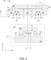
- Figure 2 is a schematic diagram of an example microfluidic reaction chamber with a reaction chamber circuit and including fluid channels, according to the present disclosure.
- the apparatus 200 may include fluid channels 104 and 106 that allow the reaction fluid to flow in and/or out of the microfluidic reaction chamber 101.
- the fluid channels 104 and 106 may be defined by side walls of the substrate. For instance, side walls 102-1, 102-2, 102-3, and 102-4 of the substrate 105 form fluid channels 104, 106.
- Fluid channel 104 and fluid channel 106 each extend a width of the substrate 105, such that fluid may flow between the microfluidic reaction chamber 101 and the environment outside of apparatus 200.
- the transparent lid 109 and the substrate 105 may, together, form the microfluidic reaction chamber 101.
- the first side wall 111 of the microfluidic reaction chamber 101 is defined in part by the transparent lid 109 and in part by the substrate 105.
- the second side wall 113 is defined in part by the transparent lid 109 and in part by the substrate 105.
- the ends of the microfluidic reaction chamber 101 may be plugged with end caps.
- the opening between the transparent lid 109 and the substrate 105 and/or the reaction chamber circuit 115 may be plugged with end caps 108-1, 108-2, and 108-3.
- the end caps 108-1, 108-2, and 108-3 shown may comprise a sealing adhesive or any other suitable adhesive.
- Figure 3 is a schematic diagram of an example microfluidic reaction chamber with a reaction chamber circuit and including a filter, according to the present disclosure.
- the description of the parts or components of apparatus 100 above applies to corresponding parts in apparatus 300.
- the example of Figure 3 illustrates an apparatus 300 comprising a substrate 105 including a proximal end 114 and a distal end 116 opposite the proximal end 114, a first fluid channel 104 traversing a width of the substrate 105, a second fluid channel 106 traversing a width of the substrate 105, and a base wall 103 disposed between the first fluid channel 104 and the second fluid channel 106.
- the apparatus 300 further includes a transparent lid 109 coupled to the proximal end 114 of the substrate 105 and the distal end 116 of the substrate 105 to form a microfluidic reaction chamber 101.
- the apparatus 300 includes a reaction chamber circuit 115 extending from the proximal end 114 of the substrate 105 to the distal end 116 of the substrate 105.
- the reaction chamber circuit 115 includes a top surface 117 proximal to the transparent lid 109 and a bottom surface 119 distal to the transparent lid 109.
- the microfluidic reaction chamber 101 includes circuitry to heat the reaction fluid, the reaction fluid including a reagent and a biologic sample for amplification of nucleic acids included in the biologic sample. Accordingly, PCR or other nucleic acid amplification techniques may be performed with the apparatus 300, and the result of amplification may be detected by the apparatus 300 itself.
- the reaction chamber circuit 115 includes a bottom surface 119 including a photodetector 121 to detect a fluorescence signal from a labeled fluorescent tag in a reaction fluid within the microfluidic reaction chamber 101. Excitation light source(s) 150 may be placed on the face side of the transparent lid 109, opposite of the top wall 107.
- the base wall 103 of the substrate 105 between the first fluid channel 104 and the second fluid channel 106 is recessed relative to a surface of the proximal end 114 and a surface of the distal end 116.
- the reaction chamber circuit 115 is coupled to the surface of the proximal end 114 of the substrate 105 and the surface of the distal end 116 of the substrate 105.
- the recessed portion of the substrate 105 in combination with the first fluid channel 104 and the second fluid channel 106 allow for the movement of the reaction fluid in and/or out of the microfluidic reaction chamber 101.
- the transparent lid 109 is coupled to the reaction chamber circuit 115 via an adhesive end cap 118 disposed at the proximal end 114 of the substrate 105 and an adhesive end cap 120 disposed at the distal end 116 of the substrate 105.
- the adhesive end cap 118 may comprise the same or different material than the adhesive end cap 120.
- the photodetector 121 is placed on the bottom surface 119 of the reaction chamber circuit 115 and facing towards substrate 105. While Figure 3 illustrates four excitation light sources, more or fewer light sources may be used. Moreover, excitation lights may be initiated sequentially to excite and detect presence of different fluorescent probes. The excitation lights may be a narrow band light sources or a plurality of different bandpass light sources illuminating the top of the transparent lid 109 to excite fluorescent markers within the microfluidic reaction chamber 101. This design enables an integrated-on-chip real time multiplex detection apparatus and increased heat efficiency with low power consumption for nucleic acid amplification and molecular diagnostics devices.
- the reaction chamber circuit 115 further includes an optical filter 123 disposed on a surface of the photodetector 121 proximal to the substrate 105.
- the filter 123 blocks unwanted traces of excitation light.
- the filter 123 may be an emission filter that allows fluorescence from the reaction fluid in the microfluidic reaction chamber 101 to reach the photodetector 121 while blocking unwanted traces of excitation light.
- Filter 123 may allow a narrow band of wavelengths to pass through it, around the peak fluorophore emission wavelength. Incident radiation outside of the wavelength range is either partially or totally blocked by the filter 123.
- the filter 123 may be disposed in direct congruent contact with the photodetector 121 on the bottom surface 119 of the reaction chamber circuit 115.
- excitation filter or a plurality of excitation filters may be disposed between the excitation light sources 150 and the transparent lid 109.
- the excitation filter(s) may also allow a narrow band of wavelengths to pass through it, around the peak fluorophore excitation wavelength, and may reflect wavelengths around the emission wavelength.
- Figure 4 is a schematic diagram of an example microfluidic reaction chamber with a reaction chamber circuit and recessed circuitry, according to the present disclosure.
- the substrate 105 includes a proximal end depression 122 at the proximal end 114 of the substrate 105 and a distal end depression 124 at the distal end 116 of the substrate 105, wherein the reaction chamber circuit 115 is disposed within the proximal end depression 122 and the distal end depression 124.
- the depth of the proximal end depression 122 is equal to the depth of the reaction chamber circuit 115, and the depth of the distal end depression 124 is equal to the depth of the reaction chamber circuit 115, such that the reaction chamber circuit 115 is relatively level with the substrate 105.
- side walls 102-1, 102-2, 102-3, and 102-4 of the substrate 105 form fluid channels 104, and 106.
- a base wall 103 of the microfluidic reaction chamber 101 between the fluid channels 104, 106 and proximal to the reaction chamber circuit 115 is recessed relative to a proximal end 114 of the substrate 105 and a distal end 116 of the substrate 105 to permit passage of the reaction fluid between the fluid channels 104, 106.
- the apparatus 400 is similar in construction to apparatus 300 illustrated in Figure 3 .
- the transparent lid 109 is coupled directly to the reaction chamber circuit 115, via side edges 164 and 166. As illustrated, the transparent lid 109 includes an enclosed cavity formed by the side edges 164 and 166 of the transparent lid 109.
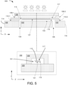
- FIG. 5 is a schematic diagram of an example microfluidic reaction chamber with a reaction chamber circuit and suspension posts, according to the present disclosure.
- the substrate 105 is not recessed, rather, posts 110-1 and 110-2 support the reaction chamber circuit 115.
- edges of the transparent lid 109 are plugged by adhesive end caps 108-1 and 108-3.
- the posts may be composed of silicon or other suitable material.
- the posts may be of a width ranging from about 50 ⁇ m thick to about 675 ⁇ m thick.
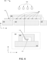
- Figure 6 is a schematic diagram of an example microfluidic reaction chamber with a reaction chamber circuit and an array of photodetectors, according to the present disclosure.
- narrow band light sources 150 may operate sequentially to detect individual fluorescent probes enabling PCR multiplexing.
- an array of photodetectors 168 may be arranged spatially along the reaction chamber circuit 115. Each photodetector of the array of photodetectors 168 may detect a different range of fluorescence, thereby enabling parallel detection of multiple fluorescent probes.
- the light sources 150 may be grouped to run sequentially or be ordered to minimize excitation of one probe by neighboring light sources.
- Figure 7 is a multi-dimensional view of an example microfluidic reaction chamber with a reaction chamber circuit, according to the present disclosure.
- the description of the parts or components of apparatus 100 above applies to corresponding parts in apparatus 700.
- Figure 7 illustrates an apparatus 700 comprising a microfluidic reaction chamber 101 to contain a reaction fluid, and a reaction chamber circuit 115 suspended within the microfluidic reaction chamber 101.
- the reaction fluid includes a reagent and a biologic sample for amplification of nucleic acids included in the biologic sample.
- the microfluidic reaction chamber 101 includes a substrate 105 including a proximal end 114 and a distal end 116 opposite the proximal end 114, and a transparent lid 109 coupled to the substrate 105.
- the reaction chamber circuit 115 is in direct fluidic contact with the reaction fluid, such that all four sides of the reaction chamber circuit 115 are in contact with the reaction fluid.
- the reaction chamber circuit 115 extends along the length of the apparatus 700 in the x plane, while fluid channels (not illustrated in Figure 7 ) allow for the passage of reaction fluid in and/or out of the microfluidic reaction chamber 101 in along the y plane.
- Figure 8 is a schematic diagram of an example microfluidic reaction chamber with a reaction chamber circuit and open capillary ends, according to the present disclosure.
- the description of the parts or components of apparatus 100 above applies to corresponding parts in apparatus 800.
- the example illustrated in Figure 8 illustrates the reaction chamber circuit 115 suspended centrally in the microfluidic reaction chamber 101.
- the ends of the reaction chamber circuit 115 are in contact with the substrate surface 105.
- Reaction fluid surrounds the reaction chamber circuit 115 on all sides, such that the distance 130 between the reaction chamber circuit 115 and the transparent lid 109 on one side, is the same as the distance 132 between the reaction chamber circuit 115 and the substrate 105 on a second side.
- Reaction fluid may enter and/or exit the microfluidic reaction chamber 101 through open capillary ends on the proximal end 114 and the distal end 116.
- An array of photodetectors 168 disposed on the reaction chamber circuit 115 faces the substrate 105 as illustrated.
- Figure 9 is a schematic diagram of another example microfluidic reaction chamber with a reaction chamber circuit and open capillary ends, according to the present disclosure.
- the description of the parts or components of apparatus 100 above applies to corresponding parts in apparatus 900.
- the example illustrated in Figure 9 illustrates the reaction chamber circuit 115 suspended centrally in the microfluidic reaction chamber 101.
- the ends of the reaction chamber circuit 115 are in contact with the substrate surface 105.
- Reaction fluid may enter and/or exit the microfluidic reaction chamber 101 through open capillary ends on the proximal end 114 and the distal end 116.
- a photodetector 121 disposed on the reaction chamber circuit 115 faces the substrate 105 as illustrated.
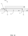
- Figure 10 is a schematic diagram of an example microfluidic reaction chamber with a reaction chamber circuit and a recessed substrate, according to the present disclosure.
- the description of the parts or components of apparatus 100 above applies to corresponding parts in apparatus 1000.
- the example of Figure 10 illustrates a reaction chamber circuit 115 mounted on a substrate 105 with adhesive 134 at each end of the reaction chamber circuit 115.
- a relief 136 in the substrate 105 allows fluid to reach the bottom side of the reaction chamber circuit 115, and a transparent lid 109 is mounted over the reaction chamber circuit 115 onto the substrate 105.
- Fluid channels 104 and 106 may be created through the substrate 105 to allow reaction fluid to enter and exit the microfluidic reaction chamber 101.
- FIG 11 is a schematic diagram of an example microfluidic reaction chamber with a reaction chamber circuit and sealing adhesive, according to the present disclosure.
- the description of the parts or components of apparatus 100 above applies to corresponding parts in apparatus 1100.
- the reaction chamber circuit 115 includes circuitry to heat the reaction fluid to specified temperatures for nucleic acid amplification, and a photodetector 121 disposed on a bottom surface 119 of the reaction chamber circuit 115 and facing the substrate 105 of the microfluidic reaction chamber 101. As described herein, the bottom surface 119 of the reaction chamber circuit 115 is distal to the transparent lid 109 relative to a top surface 117 of the reaction chamber circuit 115.
- the photodetector 121 detects a fluorescence signal from a labeled fluorescent tag in the reaction fluid indicative of amplification of the nucleic acids in the biologic sample. Moreover, a first fluid channel 104 may traverse a width of the substrate 105, and a second fluid channel 106 may traverse the width of the substrate 105. The photodetector 121 may detect the fluorescence signal from the fluorescent tag responsive to excitation by narrow band light passing through the transparent lid 109 and scattered by the substrate 105.
- the reaction chamber circuit 115 is oriented such that the circuitry faces the substrate 105.
- An aperture 130 is included such that electrical power and signal can reach the reaction chamber circuit 115 through the substrate 105.
- a relief in the substrate allows the reaction chamber circuit 115 to be in direct contact/access to the fluid in the chamber.
- FIG 12 is a schematic diagram of an example microfluidic reaction chamber with a reaction chamber circuit and a heat pipe, according to the present disclosure.
- the description of the parts or components of apparatus 100 above applies to corresponding parts in apparatus 1200.
- the heat pipe 152 may draw heat from the reaction chamber circuit 115 and from the substrate 105 to cool the microfluidic reaction chamber 101.
- the heat pipe 152 may extend around a surface of the substrate 105 and be in direct physical contact with both the substrate and the reaction chamber circuit 115, as illustrated.
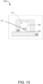
- Figure 13 is a schematic diagram of an example microfluidic reaction chamber with a displaced reaction chamber circuit, according to the present disclosure.
- the description of the parts or components of apparatus 100 above applies to corresponding parts in apparatus 1300.
- the reaction chamber circuit 115 including a top surface 117 opposite the bottom surface 119 and proximal to the transparent lid 109, and wherein the reaction chamber circuit 115 is disposed within the microfluidic reaction chamber 101 such that a distance 130 between the top surface 117 of the reaction chamber circuit 115 and the transparent lid 109 is greater than a distance 132 between the bottom surface 119 of the reaction chamber circuit 115 and the substrate 105.
- Figure 14 is a schematic diagram of an example microfluidic reaction chamber with a reaction chamber circuit and reduced transparent lid, according to the present disclosure.
- Various methods may be used to cool the reaction chamber circuit 115, including use of a heat pipe as illustrated in regard to Figure 12 , and changing a distance between the reaction chamber circuit 115 and the substrate 105 as discussed in regards to Figure 13 .
- the description of the parts or components of apparatus 100 above applies to corresponding parts in apparatus 1400.
- Figure 14 illustrates an additional method for cooling the reaction chamber circuit 115, by reducing a width of the transparent lid 109. For instance, the top width 140 of the transparent lid 109 may be less than the side width 142 of the transparent lid 109 so that heat may dissipate to the surrounding air.
- Figure 15 is an example flow diagram of a method 201, according to the present disclosure.
- the method 201 includes containing a reaction fluid for amplification of nucleic acids in a microfluidic reaction chamber.
- the microfluidic reaction chamber includes a base wall defined in part by a substrate, a top wall parallel to the base wall and defined in part by a transparent lid, a first side wall perpendicular to the base wall and defined in part by the transparent lid, and a second side wall perpendicular to the base wall and defined in part by the transparent lid.
- the method 201 includes heating the reaction fluid using a reaction chamber circuit disposed within the microfluidic reaction chamber.
- the reaction chamber circuit includes a top surface parallel to and proximal to the top wall of the microfluidic reaction chamber, a bottom surface parallel to and distal to the top wall of the microfluidic reaction chamber, a first side wall parallel to the first side wall of the microfluidic reaction chamber, and a second side wall parallel to the second side wall of the microfluidic reaction chamber.
- the method 203 includes detecting a fluorescence signal from a labeled fluorescent tag in the reaction fluid.
- the fluorescence signal is detected from a labeled fluorescent tag in the reaction fluid indicative of amplification of the nucleic acids in the biologic sample, via a photodetector disposed on a bottom surface of the reaction chamber circuit and facing a substrate of the microfluidic reaction chamber.
- the microfluidic reaction chamber includes a transparent lid. Accordingly, detecting the fluorescence signal at 207 may include detecting the fluorescence signal from the fluorescent tag responsive to excitation by narrow band light passing through the transparent lid.
- detection of a plurality of fluorescent signals may be multiplexed, such that more than one fluorescent signal may be detected at a time and using a same apparatus.
- each of the excitation light sources 150 may provide light of a different wavelength in relation to the remainder of the excitation light sources 150.
- each of the photoreactors in the array of photodetectors 168 may detect fluorescent signals associated with a different respective wavelength in relation to the remainder of the array of photodetectors 168.
- detecting the fluorescence signal may include detecting a plurality of fluorescence signals from a plurality of fluorescent tags responsive to excitation by a plurality of different light sources passing through the transparent lid.
- the plurality of light sources may be used in an ordered manner to minimize cross-excitation of photodetectors.
- detecting the fluorescence signal may include exposing the reaction fluid to the different respective light sources (e.g., 150 illustrated in Figure 6 ) in a sequential manner.
- detecting the fluorescence signal may include exposing the reaction fluid to the different respective light sources in parallel, such that groups of the light sources are illuminated at a given time.
Landscapes
- Chemical & Material Sciences (AREA)
- Health & Medical Sciences (AREA)
- Life Sciences & Earth Sciences (AREA)
- General Health & Medical Sciences (AREA)
- Chemical Kinetics & Catalysis (AREA)
- Analytical Chemistry (AREA)
- Organic Chemistry (AREA)
- Biochemistry (AREA)
- Immunology (AREA)
- Physics & Mathematics (AREA)
- Zoology (AREA)
- Proteomics, Peptides & Aminoacids (AREA)
- Wood Science & Technology (AREA)
- Engineering & Computer Science (AREA)
- Clinical Laboratory Science (AREA)
- Molecular Biology (AREA)
- Microbiology (AREA)
- General Engineering & Computer Science (AREA)
- Biophysics (AREA)
- General Physics & Mathematics (AREA)
- Nuclear Medicine, Radiotherapy & Molecular Imaging (AREA)
- Pathology (AREA)
- Bioinformatics & Cheminformatics (AREA)
- Biotechnology (AREA)
- Genetics & Genomics (AREA)
- Dispersion Chemistry (AREA)
- Hematology (AREA)
- Optics & Photonics (AREA)
- Apparatus Associated With Microorganisms And Enzymes (AREA)
- Measuring Or Testing Involving Enzymes Or Micro-Organisms (AREA)
Claims (14)
- Appareil comprenant :une chambre de réaction microfluidique (101) destinée à contenir un fluide réactionnel pour l'amplification d'acides nucléiques, la chambre de réaction microfluidique comportant une paroi de base (103) définie en partie par un substrat (105), une paroi supérieure (107) parallèle à la paroi de base et définie en partie par un couvercle transparent (109), une première paroi latérale (111) perpendiculaire à la paroi de base et définie en partie par le couvercle transparent et une seconde paroi latérale (113) perpendiculaire à la paroi de base et définie en partie par le couvercle transparent ; etun circuit (115) de chambre de réaction disposé à l'intérieur de la chambre de réaction microfluidique, le circuit de chambre de réaction comportant une surface supérieure (117) parallèle à la paroi supérieure de la chambre de réaction microfluidique et proximale par rapport à celle-ci, une surface inférieure (119) parallèle à la paroi supérieure de la chambre de réaction microfluidique et distale par rapport à celle-ci, une première paroi latérale (160) parallèle à la première paroi latérale de la chambre de réaction microfluidique et une seconde paroi latérale (162) parallèle à la seconde paroi latérale de la chambre de réaction microfluidique ;dans lequel la surface supérieure du circuit de chambre de réaction, la surface inférieure du circuit de chambre de réaction, la première paroi latérale du circuit de chambre de réaction et la seconde paroi latérale du circuit de chambre de réaction sont en contact fluidique avec le fluide réactionnel et la surface inférieure du circuit de chambre de réaction comporte un photodétecteur (121) destiné à détecter un signal de fluorescence provenant d'une étiquette fluorescente marquée dans le fluide réactionnel ; et dans lequel le circuit de chambre de réaction comporte en outre un filtre optique (123) disposé sur une surface du photodétecteur proximale par rapport au substrat.
- Appareil selon la revendication 1, dans lequel le circuit de chambre de réaction comporte un circuit de silicium semiconducteur à oxyde de métal complémentaire, CMOS, avec une circuiterie disposée sur la surface inférieure faisant face au substrat.
- Appareil selon la revendication 1, dans lequel la première paroi latérale de la chambre de réaction microfluidique est définie en partie par le couvercle transparent et en partie par le substrat et la seconde paroi latérale est définie en partie par le couvercle transparent et en partie par le substrat.
- Appareil selon la revendication 3, dans lequel les parois latérales (102-1, 102-2, 102-3, 102-4) du substrat forment des canaux fluidiques (104, 106) et dans lequel une paroi de base de la chambre de réaction microfluidique entre les canaux fluidiques et proximale par rapport au circuit de chambre de réaction est en retrait par rapport à une extrémité proximale du substrat et à une extrémité distale du substrat afin de permettre le passage du fluide réactionnel entre les canaux fluidiques.
- Appareil selon la revendication 1, selon lequel :le substrat comporte une extrémité proximale (114) et une extrémité distale (116) opposée à l'extrémité proximale ;un premier canal à fluide (104) traverse une largeur du substrat ;un second canal fluidique (106) traverse une largeur du substrat, selon lequel la paroi de base est disposée entre le premier canal fluidique et le second canal fluidique ;le couvercle transparent est couplé à l'extrémité proximale du substrat et à l'extrémité distale du substrat afin de former la chambre de réaction microfluidique ; et le circuit de chambre de réaction s'étend depuis l'extrémité proximale du substrat à l'extrémité distale du substrat.
- Appareil selon la revendication 5, selon lequel la chambre de réaction microfluidique comporte une circuiterie destinée à chauffer le fluide réactionnel, le fluide réactionnel comportant un réactif et un échantillon biologique pour l'amplification d'acides nucléiques inclus dans l'échantillon biologique.
- Appareil selon la revendication 5, dans lequel la paroi de base du substrat entre le premier canal fluidique et le second canal fluidique est en retrait par rapport à une surface de l'extrémité proximale et à une surface de l'extrémité distale et le circuit de chambre de réaction est couplé à la surface de l'extrémité proximale du substrat et à la surface de l'extrémité distale du substrat.
- Appareil selon la revendication 5, dans lequel le couvercle transparent est couplé au circuit de chambre de réaction par l'intermédiaire d'un capuchon d'extrémité adhésif (118) disposé au niveau de l'extrémité proximale du substrat et d'un capuchon d'extrémité adhésif (120) disposé au niveau de l'extrémité distale du substrat.
- Appareil selon la revendication 5, dans lequel le substrat comporte une dépression (122) d'extrémité proximale au niveau de l'extrémité proximale du substrat et une dépression (124) d'extrémité distale au niveau de l'extrémité distale du substrat, dans lequel le circuit de chambre de réaction est disposé à l'intérieur de la dépression d'extrémité proximale et de la dépression d'extrémité distale.
- Procédé (201) consistant à :contenir (203) un fluide réactionnel pour l'amplification d'acides nucléiques dans une chambre de réaction microfluidique, la chambre de réaction microfluidique comportant une paroi de base définie en partie par un substrat, une paroi supérieure parallèle à la paroi de base et définie en partie par un couvercle transparent, une première paroi latérale perpendiculaire à la paroi de base et définie en partie par le couvercle transparent et une seconde paroi latérale perpendiculaire à la paroi de base et définie en partie par le couvercle transparent ;chauffer (205) le fluide réactionnel à l'aide d'un circuit de chambre de réaction disposé à l'intérieur de la chambre de réaction microfluidique, le circuit de chambre de réaction comportant une surface supérieure parallèle à la paroi supérieure de la chambre de réaction microfluidique et proximale par rapport à celle-ci, une surface inférieure parallèle à la paroi supérieure de la chambre de réaction microfluidique et distale par rapport à celle-ci, une première paroi latérale parallèle à la première paroi latérale de la chambre de réaction microfluidique et une seconde paroi latérale parallèle à la seconde paroi latérale de la chambre de réaction microfluidique, dans lequel la surface supérieure du circuit de chambre de réaction, la surface inférieure du circuit de chambre de réaction, la première paroi latérale du circuit de chambre de réaction et la seconde paroi latérale du circuit de chambre de réaction sont en contact fluidique avec le fluide réactionnel et dans lequel le circuit de chambre de réaction comporte en outre un filtre optique disposé sur une surface du photodétecteur proximale par rapport au substrat ; et détecter (207) un signal de fluorescence provenant d'une étiquette fluorescente marquée dans le fluide réactionnel indiquant l'amplification des acides nucléiques dans le fluide réactionnel, par l'intermédiaire d'un photodétecteur disposé sur une surface inférieure du circuit de chambre de réaction et faisant face à un substrat de la chambre de réaction microfluidique.
- Procédé selon la revendication 10, dans lequel la chambre de réaction microfluidique comporte un couvercle transparent et dans lequel la détection du signal de fluorescence comporte la détection du signal de fluorescence de l'étiquette fluorescente en réponse à l'excitation par une lumière à bande étroite passant à travers le couvercle transparent.
- Procédé selon la revendication 10, dans lequel la détection du signal de fluorescence comporte la détection d'une pluralité de signaux de fluorescence provenant d'une pluralité d'étiquettes fluorescentes en réponse à l'excitation par une pluralité de sources lumineuses différentes passant à travers le couvercle transparent.
- Procédé selon la revendication 12, dans lequel la détection du signal de fluorescence comporte la soumission du fluide réactionnel aux sources lumineuses (150) différentes de manière séquentielle.
- Procédé selon la revendication 12, dans lequel la détection du signal de fluorescence comporte la soumission du fluide réactionnel aux sources lumineuses différentes respectives en parallèle.
Applications Claiming Priority (1)
| Application Number | Priority Date | Filing Date | Title |
|---|---|---|---|
| PCT/US2020/014448 WO2021150212A1 (fr) | 2020-01-21 | 2020-01-21 | Chambre de réaction microfluidique dotée d'un circuit de chambre de réaction |
Publications (3)
| Publication Number | Publication Date |
|---|---|
| EP4052018A1 EP4052018A1 (fr) | 2022-09-07 |
| EP4052018A4 EP4052018A4 (fr) | 2022-11-02 |
| EP4052018B1 true EP4052018B1 (fr) | 2025-03-26 |
Family
ID=76993267
Family Applications (1)
| Application Number | Title | Priority Date | Filing Date |
|---|---|---|---|
| EP20915018.4A Active EP4052018B1 (fr) | 2020-01-21 | 2020-01-21 | Chambre de réaction microfluidique dotée d'un circuit de chambre de réaction et procédé |
Country Status (3)
| Country | Link |
|---|---|
| US (1) | US12599901B2 (fr) |
| EP (1) | EP4052018B1 (fr) |
| WO (1) | WO2021150212A1 (fr) |
Families Citing this family (1)
| Publication number | Priority date | Publication date | Assignee | Title |
|---|---|---|---|---|
| CN108593416B (zh) * | 2018-04-08 | 2020-09-08 | 国家纳米科学中心 | 微纳粒子检测系统及方法 |
Family Cites Families (12)
| Publication number | Priority date | Publication date | Assignee | Title |
|---|---|---|---|---|
| US6833242B2 (en) | 1997-09-23 | 2004-12-21 | California Institute Of Technology | Methods for detecting and sorting polynucleotides based on size |
| US6197503B1 (en) | 1997-11-26 | 2001-03-06 | Ut-Battelle, Llc | Integrated circuit biochip microsystem containing lens |
| US6927049B2 (en) * | 1999-07-21 | 2005-08-09 | The Regents Of The University Of California | Cell viability detection using electrical measurements |
| KR100700126B1 (ko) | 2003-03-10 | 2007-03-28 | 가시오게산키 가부시키가이샤 | Dna 분석 장치, dna 센서, 그리고 분석 방법 |
| FR2881363B1 (fr) * | 2005-02-02 | 2008-03-14 | Commissariat Energie Atomique | Dispositif d'analyses biologiques avec detecteur integre |
| WO2007063457A2 (fr) | 2005-11-29 | 2007-06-07 | Koninklijke Philips Electronics N.V. | Dispositif de puce biologique comportant un compartiment d'echantillon et un element photosensible, procede de detection de particules fluorescentes dans au moins un compartiment d'echantillon d'un dispositif de puce biologique |
| US20110312781A1 (en) | 2010-06-17 | 2011-12-22 | Geneasys Pty Ltd | Loc with digital memory to store genetic data updates |
| EP2632593B1 (fr) * | 2010-10-27 | 2021-09-29 | Illumina, Inc. | Cellules d'écoulement pour analyse biologique ou chimique |
| CN110411998B (zh) | 2013-12-10 | 2022-06-07 | 伊鲁米那股份有限公司 | 用于生物或化学分析的生物传感器及其制造方法 |
| JP6775223B2 (ja) | 2016-10-27 | 2020-10-28 | シャープ株式会社 | 蛍光検査システム、分子検査方法及び蛍光検査方法 |
| EP3560593B1 (fr) | 2018-04-25 | 2024-06-05 | OPTOLANE Technologies Inc. | Cartouche de pcr numérique en temps réel |
| EP3880791A4 (fr) | 2019-04-29 | 2022-03-30 | Hewlett-Packard Development Company, L.P. | Chambre de réaction microfluidique pour amplification d'acides nucléiques |
-
2020
- 2020-01-21 EP EP20915018.4A patent/EP4052018B1/fr active Active
- 2020-01-21 WO PCT/US2020/014448 patent/WO2021150212A1/fr not_active Ceased
- 2020-01-21 US US17/782,598 patent/US12599901B2/en active Active
Also Published As
| Publication number | Publication date |
|---|---|
| US20230001412A1 (en) | 2023-01-05 |
| EP4052018A4 (fr) | 2022-11-02 |
| WO2021150212A1 (fr) | 2021-07-29 |
| US12599901B2 (en) | 2026-04-14 |
| EP4052018A1 (fr) | 2022-09-07 |
Similar Documents
| Publication | Publication Date | Title |
|---|---|---|
| EP2178641B1 (fr) | Procédés et dispositifs permettant des mesures corrélées et multiparamètres portant sur une seule cellule, ainsi que le recueil de résidus de matériaux biologiques | |
| EP1246700B1 (fr) | Systeme d'amplification en chaine par polymerase | |
| US5958349A (en) | Reaction vessel for heat-exchanging chemical processes | |
| AU2011202316B2 (en) | Instrument and methods for mixing the contents of a detection chamber | |
| US20060027317A1 (en) | Methods of sealing micro wells | |
| US20070003443A1 (en) | Thermal-cycling pipette tip | |
| US20140113298A1 (en) | Detection and mixing in a conduit in integrated bioanalysis systems | |
| CN101300352A (zh) | 检测、分析和鉴定基因组dna的方法和分子诊断装置 | |
| JP2011038922A (ja) | 光検出用チップおよび該光検出用チップを用いた光検出装置 | |
| US8778637B2 (en) | Method and apparatus for applying continuous flow and uniform temperature to generate thermal melting curves in a microfluidic device | |
| EP2074409A2 (fr) | Procédés et systèmes pour une détection avec une irradiation frontale | |
| US12599901B2 (en) | Microfluidic reaction chamber with a reaction chamber circuit | |
| US7186989B2 (en) | Low thermal mass fluorometer | |
| Sundberg et al. | Solution-phase DNA mutation scanning and SNP genotyping by nanoliter melting analysis | |
| KR20030096877A (ko) | 핵산증폭반응 산물의 실시간 모니터링 장치 | |
| KR20140023370A (ko) | 발광 검출 방법 | |
| AU2012203830B2 (en) | Instrument and methods for mixing the contents of a detection chamber | |
| WO2007063457A2 (fr) | Dispositif de puce biologique comportant un compartiment d'echantillon et un element photosensible, procede de detection de particules fluorescentes dans au moins un compartiment d'echantillon d'un dispositif de puce biologique | |
| Sayers et al. | A real-time continuous flow polymerase chain reactor for DNA expression quantification | |
| Chang et al. | Fluorescence Sensing on the Microscale | |
| WO2022186818A1 (fr) | Particules de chambre pour traitement d'acide nucléique | |
| WO2022177558A1 (fr) | Amplification d'acides nucléiques microfluidique | |
| EP1738829A1 (fr) | Systeme d'amplification en chaine par polymerase | |
| Chien et al. | Simultaneous quantification for Hepatitis B virus and Hepatitis C virus using real-time PCR Lab-on-a-chip | |
| HK1206673B (en) | Methods and devices for correlated, multi-parameter single cell measurements and recovery of remnant biological material |
Legal Events
| Date | Code | Title | Description |
|---|---|---|---|
| STAA | Information on the status of an ep patent application or granted ep patent |
Free format text: STATUS: THE INTERNATIONAL PUBLICATION HAS BEEN MADE |
|
| PUAI | Public reference made under article 153(3) epc to a published international application that has entered the european phase |
Free format text: ORIGINAL CODE: 0009012 |
|
| STAA | Information on the status of an ep patent application or granted ep patent |
Free format text: STATUS: REQUEST FOR EXAMINATION WAS MADE |
|
| 17P | Request for examination filed |
Effective date: 20220601 |
|
| AK | Designated contracting states |
Kind code of ref document: A1 Designated state(s): AL AT BE BG CH CY CZ DE DK EE ES FI FR GB GR HR HU IE IS IT LI LT LU LV MC MK MT NL NO PL PT RO RS SE SI SK SM TR |
|
| REG | Reference to a national code |
Ref country code: DE Ref legal event code: R079 Free format text: PREVIOUS MAIN CLASS: G01N0021010000 Ipc: G01N0021640000 Ref document number: 602020048538 Country of ref document: DE |
|
| A4 | Supplementary search report drawn up and despatched |
Effective date: 20220930 |
|
| RIC1 | Information provided on ipc code assigned before grant |
Ipc: G01N 21/05 20060101ALN20220926BHEP Ipc: G01N 21/03 20060101ALN20220926BHEP Ipc: B01L 3/00 20060101ALI20220926BHEP Ipc: C12Q 1/6844 20180101ALI20220926BHEP Ipc: G01N 21/64 20060101AFI20220926BHEP |
|
| DAV | Request for validation of the european patent (deleted) | ||
| DAX | Request for extension of the european patent (deleted) | ||
| GRAP | Despatch of communication of intention to grant a patent |
Free format text: ORIGINAL CODE: EPIDOSNIGR1 |
|
| STAA | Information on the status of an ep patent application or granted ep patent |
Free format text: STATUS: GRANT OF PATENT IS INTENDED |
|
| RIC1 | Information provided on ipc code assigned before grant |
Ipc: B01L 7/00 20060101ALN20241122BHEP Ipc: G01N 21/05 20060101ALN20241122BHEP Ipc: G01N 21/03 20060101ALN20241122BHEP Ipc: B01L 3/00 20060101ALI20241122BHEP Ipc: C12Q 1/6844 20180101ALI20241122BHEP Ipc: G01N 21/64 20060101AFI20241122BHEP |
|
| INTG | Intention to grant announced |
Effective date: 20241211 |
|
| GRAS | Grant fee paid |
Free format text: ORIGINAL CODE: EPIDOSNIGR3 |
|
| GRAA | (expected) grant |
Free format text: ORIGINAL CODE: 0009210 |
|
| STAA | Information on the status of an ep patent application or granted ep patent |
Free format text: STATUS: THE PATENT HAS BEEN GRANTED |
|
| AK | Designated contracting states |
Kind code of ref document: B1 Designated state(s): AL AT BE BG CH CY CZ DE DK EE ES FI FR GB GR HR HU IE IS IT LI LT LU LV MC MK MT NL NO PL PT RO RS SE SI SK SM TR |
|
| REG | Reference to a national code |
Ref country code: GB Ref legal event code: FG4D |
|
| REG | Reference to a national code |
Ref country code: CH Ref legal event code: EP |
|
| REG | Reference to a national code |
Ref country code: DE Ref legal event code: R096 Ref document number: 602020048538 Country of ref document: DE |
|
| REG | Reference to a national code |
Ref country code: IE Ref legal event code: FG4D |
|
| PG25 | Lapsed in a contracting state [announced via postgrant information from national office to epo] |
Ref country code: RS Free format text: LAPSE BECAUSE OF FAILURE TO SUBMIT A TRANSLATION OF THE DESCRIPTION OR TO PAY THE FEE WITHIN THE PRESCRIBED TIME-LIMIT Effective date: 20250626 |
|
| PG25 | Lapsed in a contracting state [announced via postgrant information from national office to epo] |
Ref country code: FI Free format text: LAPSE BECAUSE OF FAILURE TO SUBMIT A TRANSLATION OF THE DESCRIPTION OR TO PAY THE FEE WITHIN THE PRESCRIBED TIME-LIMIT Effective date: 20250326 |
|
| REG | Reference to a national code |
Ref country code: LT Ref legal event code: MG9D |
|
| PG25 | Lapsed in a contracting state [announced via postgrant information from national office to epo] |
Ref country code: NO Free format text: LAPSE BECAUSE OF FAILURE TO SUBMIT A TRANSLATION OF THE DESCRIPTION OR TO PAY THE FEE WITHIN THE PRESCRIBED TIME-LIMIT Effective date: 20250626 |
|
| PG25 | Lapsed in a contracting state [announced via postgrant information from national office to epo] |
Ref country code: HR Free format text: LAPSE BECAUSE OF FAILURE TO SUBMIT A TRANSLATION OF THE DESCRIPTION OR TO PAY THE FEE WITHIN THE PRESCRIBED TIME-LIMIT Effective date: 20250326 |
|
| PG25 | Lapsed in a contracting state [announced via postgrant information from national office to epo] |
Ref country code: LV Free format text: LAPSE BECAUSE OF FAILURE TO SUBMIT A TRANSLATION OF THE DESCRIPTION OR TO PAY THE FEE WITHIN THE PRESCRIBED TIME-LIMIT Effective date: 20250326 |
|
| PG25 | Lapsed in a contracting state [announced via postgrant information from national office to epo] |
Ref country code: GR Free format text: LAPSE BECAUSE OF FAILURE TO SUBMIT A TRANSLATION OF THE DESCRIPTION OR TO PAY THE FEE WITHIN THE PRESCRIBED TIME-LIMIT Effective date: 20250627 Ref country code: BG Free format text: LAPSE BECAUSE OF FAILURE TO SUBMIT A TRANSLATION OF THE DESCRIPTION OR TO PAY THE FEE WITHIN THE PRESCRIBED TIME-LIMIT Effective date: 20250326 |
|
| REG | Reference to a national code |
Ref country code: NL Ref legal event code: MP Effective date: 20250326 |
|
| PG25 | Lapsed in a contracting state [announced via postgrant information from national office to epo] |
Ref country code: NL Free format text: LAPSE BECAUSE OF FAILURE TO SUBMIT A TRANSLATION OF THE DESCRIPTION OR TO PAY THE FEE WITHIN THE PRESCRIBED TIME-LIMIT Effective date: 20250326 |
|
| PG25 | Lapsed in a contracting state [announced via postgrant information from national office to epo] |
Ref country code: SE Free format text: LAPSE BECAUSE OF FAILURE TO SUBMIT A TRANSLATION OF THE DESCRIPTION OR TO PAY THE FEE WITHIN THE PRESCRIBED TIME-LIMIT Effective date: 20250326 |
|
| REG | Reference to a national code |
Ref country code: AT Ref legal event code: MK05 Ref document number: 1779401 Country of ref document: AT Kind code of ref document: T Effective date: 20250326 |
|
| PG25 | Lapsed in a contracting state [announced via postgrant information from national office to epo] |
Ref country code: SM Free format text: LAPSE BECAUSE OF FAILURE TO SUBMIT A TRANSLATION OF THE DESCRIPTION OR TO PAY THE FEE WITHIN THE PRESCRIBED TIME-LIMIT Effective date: 20250326 |
|
| PG25 | Lapsed in a contracting state [announced via postgrant information from national office to epo] |
Ref country code: PT Free format text: LAPSE BECAUSE OF FAILURE TO SUBMIT A TRANSLATION OF THE DESCRIPTION OR TO PAY THE FEE WITHIN THE PRESCRIBED TIME-LIMIT Effective date: 20250728 Ref country code: ES Free format text: LAPSE BECAUSE OF FAILURE TO SUBMIT A TRANSLATION OF THE DESCRIPTION OR TO PAY THE FEE WITHIN THE PRESCRIBED TIME-LIMIT Effective date: 20250326 |
|
| PG25 | Lapsed in a contracting state [announced via postgrant information from national office to epo] |
Ref country code: IT Free format text: LAPSE BECAUSE OF FAILURE TO SUBMIT A TRANSLATION OF THE DESCRIPTION OR TO PAY THE FEE WITHIN THE PRESCRIBED TIME-LIMIT Effective date: 20250326 Ref country code: PL Free format text: LAPSE BECAUSE OF FAILURE TO SUBMIT A TRANSLATION OF THE DESCRIPTION OR TO PAY THE FEE WITHIN THE PRESCRIBED TIME-LIMIT Effective date: 20250326 |
|
| PG25 | Lapsed in a contracting state [announced via postgrant information from national office to epo] |
Ref country code: AT Free format text: LAPSE BECAUSE OF FAILURE TO SUBMIT A TRANSLATION OF THE DESCRIPTION OR TO PAY THE FEE WITHIN THE PRESCRIBED TIME-LIMIT Effective date: 20250326 |
|
| PG25 | Lapsed in a contracting state [announced via postgrant information from national office to epo] |
Ref country code: EE Free format text: LAPSE BECAUSE OF FAILURE TO SUBMIT A TRANSLATION OF THE DESCRIPTION OR TO PAY THE FEE WITHIN THE PRESCRIBED TIME-LIMIT Effective date: 20250326 |
|
| PG25 | Lapsed in a contracting state [announced via postgrant information from national office to epo] |
Ref country code: RO Free format text: LAPSE BECAUSE OF FAILURE TO SUBMIT A TRANSLATION OF THE DESCRIPTION OR TO PAY THE FEE WITHIN THE PRESCRIBED TIME-LIMIT Effective date: 20250326 |
|
| PG25 | Lapsed in a contracting state [announced via postgrant information from national office to epo] |
Ref country code: SK Free format text: LAPSE BECAUSE OF FAILURE TO SUBMIT A TRANSLATION OF THE DESCRIPTION OR TO PAY THE FEE WITHIN THE PRESCRIBED TIME-LIMIT Effective date: 20250326 |
|
| PG25 | Lapsed in a contracting state [announced via postgrant information from national office to epo] |
Ref country code: IS Free format text: LAPSE BECAUSE OF FAILURE TO SUBMIT A TRANSLATION OF THE DESCRIPTION OR TO PAY THE FEE WITHIN THE PRESCRIBED TIME-LIMIT Effective date: 20250726 |
|
| REG | Reference to a national code |
Ref country code: DE Ref legal event code: R097 Ref document number: 602020048538 Country of ref document: DE |
|
| PG25 | Lapsed in a contracting state [announced via postgrant information from national office to epo] |
Ref country code: DK Free format text: LAPSE BECAUSE OF FAILURE TO SUBMIT A TRANSLATION OF THE DESCRIPTION OR TO PAY THE FEE WITHIN THE PRESCRIBED TIME-LIMIT Effective date: 20250326 |
|
| PG25 | Lapsed in a contracting state [announced via postgrant information from national office to epo] |
Ref country code: CZ Free format text: LAPSE BECAUSE OF FAILURE TO SUBMIT A TRANSLATION OF THE DESCRIPTION OR TO PAY THE FEE WITHIN THE PRESCRIBED TIME-LIMIT Effective date: 20250326 |
|
| PLBE | No opposition filed within time limit |
Free format text: ORIGINAL CODE: 0009261 |
|
| STAA | Information on the status of an ep patent application or granted ep patent |
Free format text: STATUS: NO OPPOSITION FILED WITHIN TIME LIMIT |
|
| REG | Reference to a national code |
Ref country code: CH Ref legal event code: L10 Free format text: ST27 STATUS EVENT CODE: U-0-0-L10-L00 (AS PROVIDED BY THE NATIONAL OFFICE) Effective date: 20260211 |
|
| 26N | No opposition filed |
Effective date: 20260105 |
|
| PGFP | Annual fee paid to national office [announced via postgrant information from national office to epo] |
Ref country code: DE Payment date: 20251217 Year of fee payment: 7 |