EP4052033B1 - Elektrophysiologisches messgerät und messverfahren zur erfassung mindestens eines elektrischen messwerts an einer biologischen zellprobe - Google Patents
Elektrophysiologisches messgerät und messverfahren zur erfassung mindestens eines elektrischen messwerts an einer biologischen zellprobe Download PDFInfo
- Publication number
- EP4052033B1 EP4052033B1 EP20797746.3A EP20797746A EP4052033B1 EP 4052033 B1 EP4052033 B1 EP 4052033B1 EP 20797746 A EP20797746 A EP 20797746A EP 4052033 B1 EP4052033 B1 EP 4052033B1
- Authority
- EP
- European Patent Office
- Prior art keywords
- cell sample
- substrate
- nanoelectrodes
- cell
- nanoelectrode
- Prior art date
- Legal status (The legal status is an assumption and is not a legal conclusion. Google has not performed a legal analysis and makes no representation as to the accuracy of the status listed.)
- Active
Links
Images






Classifications
-
- G—PHYSICS
- G01—MEASURING; TESTING
- G01N—INVESTIGATING OR ANALYSING MATERIALS BY DETERMINING THEIR CHEMICAL OR PHYSICAL PROPERTIES
- G01N33/00—Investigating or analysing materials by specific methods not covered by groups G01N1/00 - G01N31/00
- G01N33/48—Biological material, e.g. blood, urine; Haemocytometers
- G01N33/483—Physical analysis of biological material
- G01N33/487—Physical analysis of biological material of liquid biological material
- G01N33/48707—Physical analysis of biological material of liquid biological material by electrical means
- G01N33/48728—Investigating individual cells, e.g. by patch clamp, voltage clamp
Definitions
- the invention relates to electrophysiological measuring devices and electrophysiological measuring methods for detecting at least one electrical measurement value on a biological cell sample, in particular a measuring device and a measuring method for detecting an action potential on at least one cell membrane of the cell sample and/or an ion current through at least one cell membrane of the cell sample. Substrates for receiving biological cells and their applications are also described.
- the invention is applicable to the handling and in particular characterization of biological cell samples, in particular individual cells or cell aggregates, in pharmacology, medicine, biochemistry and/or biomedicine.
- Electrophysiological investigations on cell samples from at least one biological cell or cell aggregates include in particular the measurement of ion currents through the cell membrane ("patch-clamp” measurement) or the measurement of action potentials on the cell membrane (“current-clamp” measurement).
- a compensation current is passed into the sample in order to keep the membrane voltage constant
- the injection of a compensation current during the measurement can be dispensed with due to the low current amplitudes.
- a nanoelectrode array comprises a large number of compact ([4], [8]) or hollow ([5] to [8]) electrode tips with typical diameters in the sub-micrometer range, which protrude from a solid substrate, for example as a matrix arrangement.
- the electrode tips In order to carry out an intracellular measurement (measurement inside the cell), i.e. to establish direct electrical contact between the electrode and the cytosol inside the cell, the electrode tips must penetrate the cell membrane.
- the cytosol would be isolated from the electrode tip by the cell membrane, so that practically only an extracellular measurement (measurement on the outside of the cell) could be carried out.
- the extracellular measurement is less meaningful and, due to the relatively low potentials, less accurate than the intracellular measurement.
- nanostructured metal electrodes are used to detect extracellular signals from biological cells derived.
- the nanostructured metal electrodes are unsuitable for intracellular measurements.
- electrophysiological potentials to generate electrical currents.
- the tips of the nanoelectrodes are provided with a coating that activates endocytosis of the membrane and thus facilitates the absorption of the electrodes into the interior of the cells. This technique is unsuitable for electrophysiological studies because the endocytosis coating can affect the cells in an undesirable way.
- Another disadvantage of conventional nanoelectrode arrays can arise from natural cell movement that adherent biological cells can perform due to an ongoing rearrangement of their cell-substrate contacts. Cells can migrate over a substrate with nanoelectrodes during the measurement, which distorts the measurement result. Natural cell movement can be restricted by an adhesion-reducing substrate coating. However, the substrate coating has the disadvantage that it can influence the physiology of the cells.
- Structured substrates with so-called microgrooves are known from [14] and [15], which are intended to influence the cultivation of adherent cells, but in practice can have limited effectiveness. In general, it can also be disadvantageous if conventional substrates carry coatings, such as Matrigel or fibronectin, which can cause undesirable biochemical changes in cells.
- an electrophysiological measuring device in which a cell is held under the effect of a suction pressure on a pore in which a tip-shaped electrode is arranged. Measures for a stable holding of the cell on the pore are not disclosed in [24].
- the object of the invention is to provide an improved electrophysiological measuring device and/or an improved electrophysiological measuring method for recording at least one electrical measurement value on a biological cell sample, with which disadvantages and limitations of conventional techniques can be avoided.
- the invention should in particular enable electrophysiological examinations with increased accuracy, reproducibility and reliability, be suitable for intracellular measurement on cells, allow routine applications and/or have an expanded area of application.
- the invention should provide an improved electrophysiological measuring device and/or an improved electrophysiological measuring method, whereby better adhesion of cells to substrate surfaces is enabled.
- an electrophysiological measuring device which is designed to record at least one electrical measurement value on a biological cell sample.
- the electrophysiological measuring device comprises a substrate device which is designed to receive the cell sample.
- the cell sample comprises a single biological cell or a plurality of cells (e.g. cell cluster, cell aggregate, or tissue section, in particular cell aggregate with cells connected by nexus contacts).
- the substrate device has a substrate with a substrate surface for the adherent positioning of cells.
- the substrate surface preferably has a flat shape, whereby a reference plane (hereinafter also: xy plane) of the substrate, whereby the substrate surface itself can be flat or structured with elevations and/or depressions.
- the substrate device is configured to provide at least one liquid film, preferably a liquid layer or a liquid bath, for covering the cells and is preferably, but not necessarily, formed as part of a chamber (vessel) for this purpose.
- the chamber can be closed (e.g. bowl) or designed for flow (e.g. channel).
- the chamber can have a projection for fixing the cell sample in a chamber wall above the substrate device.
- the substrate device can be one- or multi-part and/or at least partially formed by parts of the measuring device that are configured for other functions in addition to receiving the cell sample.
- the substrate device comprises in particular a substrate that in various configurations comprises a single substrate body for receiving the cell sample or can be combined with other components, such as membranes.
- the substrate has a substrate surface that is preferably made of a cell-compatible material and, for example, has a cell-compatible coating.
- the substrate surface, in particular the coating advantageously fulfills a dual function with regard to the insulation of the conductive tip of at least one nanoelectrode and the direct, tight contact with the cell membrane.
- the electrophysiological measuring device further comprises an electrode device with at least one, preferably a plurality of nanoelectrodes (in particular at least two nanoelectrodes).
- the electrode device has a single or a plurality of nanoelectrodes. If features are described below with reference to several nanoelectrodes, these features are preferably also given in the same way in variants with a single nanoelectrode.
- Each nanoelectrode extends straight in a longitudinal direction (hereinafter also: z-direction) from an electrode carrier to a free electrode tip (free end).
- the diameter of the nanoelectrodes is less than 1 ⁇ m, preferably less than or equal to 800 nm, e.g. less than or equal to 500 nm, and/or at least 50 nm.
- the longitudinal length of the nanoelectrodes is preferably at least 100 nm, particularly preferably at least 1 ⁇ m, and/or at most 10 ⁇ m, particularly preferably at most 3 ⁇ m.
- the electrode device and the substrate device are arranged such that the nanoelectrodes can be introduced intracellularly into the cell sample when the latter is received by the substrate device.
- the nanoelectrodes have a configuration such that they can be inserted into at least one of the cells the cell sample.
- the electrode device and the substrate device are connected to one another.
- the nanoelectrodes are arranged such that the longitudinal direction of the nanoelectrodes is perpendicular to the reference plane of the substrate surface.
- the nanoelectrodes are positioned relative to the substrate surface such that the free electrode tips are at a vertical distance from the substrate surface, so that the nanoelectrodes are in direct contact with the cytosol in the cell interior of the cell sample on the substrate surface.
- the vertical distance from the substrate surface is preferably at least 1 ⁇ m and/or at most 1 mm, but can also be selected in the range of less than 1 ⁇ m.
- the nanoelectrodes can sit on a shaft and form columns or taper conically to a tip.
- the shaft can be formed by a cylinder or truncated cone with a height of 1 ⁇ m to 50 ⁇ m, onto which the nanoelectrodes are placed. However, the shaft can also be higher.
- the electrode device of the electrophysiological measuring device can be coupled to a measuring device or is permanently connected.
- the measuring device is configured to record electrical quantities, in particular voltages and/or currents, at the nanoelectrodes and to determine electrophysiological measured values, such as resting potentials, action potentials or ion currents through cell membranes.
- the measurement of ion currents through the cell membrane (“patch clamp” measurement) or the measurement of action potentials on the cell membrane (“current clamp” measurement) is carried out. Simultaneous or consecutive measurements of both action potentials and ion currents are also possible using the cell-attached patch clamp method on a cell sample.
- the electrophysiological measuring device is equipped with an actuating device which is designed for a mutual movement of the nanoelectrodes and/or the cell sample along the longitudinal direction of the nanoelectrodes.
- the mutual movement is formed in such a way that the nanoelectrodes can penetrate into the cell sample when the latter is received by the substrate device.
- the actuating device acts on the nanoelectrodes, in particular their electrode carriers and/or the nanoelectrodes themselves, and/or the substrate device, in particular the substrate or a lateral chamber wall, so that the nanoelectrodes are actively moved towards the cell sample and/or the cell sample towards the nanoelectrodes.
- the actuating device acts in such a way that the nanoelectrodes penetrate into the cell sample at the same time.
- the relative movement preferably extends over a distance in the range from 100 nm to 5 mm.
- the provision of the actuator of the electrophysiological measuring device overcomes numerous limitations of conventional techniques.
- the nanoelectrodes in particular their electrode tips, are placed in a targeted manner in the biological cell sample.
- the introduction of the nanoelectrodes into the cytosol is triggered by the actuation of the actuator.
- the measurement is not dependent on spontaneous processes or processes occurring or triggered by electrode coatings.
- the accuracy, reproducibility and reliability of the measurement are improved by the positioning of the nanoelectrodes in the cell sample.
- the inventors have found that biological cell samples allow the simultaneous introduction of a large number of nanoelectrodes with penetration of the cell membrane without damaging the nanoelectrodes.
- the actuator By allowing the actuator to move the nanoelectrodes and/or the cell sample relative to one another along the longitudinal direction of the nanoelectrodes, undesirable lateral forces that could bend nanoelectrodes are avoided or reduced to a negligible level.
- the inventors have further discovered that the cell membrane has a stabilizing effect on the nanoelectrodes, so that they are guided from the cell membrane into the cytosol.
- the above object is achieved by an electrophysiological measuring method in which at least one electrical measurement value is recorded intracellularly on a biological cell sample.
- the measuring method which is preferably carried out with the electrophysiological measuring device according to the first general aspect of the invention, comprises the following steps.
- the cell sample comprising a single cell or a plurality of cells, is arranged on a substrate device.
- the arrangement of the cell sample on the substrate device comprises, for example, positioning a cell suspension on a substrate of the substrate device, optionally followed by culturing the cell sample.
- the arrangement of the cell sample comprises positioning the substrate device in a cell suspension, followed by transferring at least one cell to the substrate device.
- a plurality of nanoelectrodes of an electrode device are positioned such that the nanoelectrodes, in particular their electrode tips, protrude intracellularly into the cell sample.
- the nanoelectrodes extend parallel to each other in a longitudinal direction and perpendicular to a reference plane, which represents a lateral extension of the substrate surface.
- the positioning of the nanoelectrodes comprises a movement of the nanoelectrodes and/or the cell sample along the longitudinal direction of the nanoelectrodes with an adjusting device until the nanoelectrodes protrude into the cell sample and form a form direct electrical contact with the interior of the cell. At least one electrical measurement value is then taken from the cell sample.
- the penetration of cells in the cell sample can occur in such a way that the nanoelectrodes first contact the cell membrane with their tips and deform it (destabilization) and then penetrate into the cells through a pulse-shaped forward movement.
- the pulse-shaped forward movement can be provided by a suitable control of the actuating device, in particular control of the actuator by the drive unit.
- the provision of the adjusting device offers the advantage that the cell sample can be arranged spatially separated from the nanoelectrodes before the measurement. Unintentional penetration of the nanoelectrodes into the cells can be prevented or reduced to a negligible level.
- Parts of the measuring device, in particular the substrate feeder and/or the adjusting device form a separating device that is designed to spatially separate the cell sample from the nanoelectrodes before the adjusting device is operated.
- a temporal reference point is set for the electrophysiological measurement, so that this can in particular include the recording of a time dependency of electrophysiological variables.
- the actuating device comprises a suction device as an actuator and drive unit, which is designed to draw the cell sample to the nanoelectrodes.
- the suction device is formed by at least one suction opening and a pump device (suction pump), which is connected to the space above the substrate surface via the at least one suction opening in the substrate device.
- the substrate is equipped with the at least one nanoelectrode.
- the nanoelectrodes are preferably fixed to the substrate, arranged to protrude from the substrate or to be sunk into the substrate.
- the at least one suction opening is formed in such a way that when the at least one suction opening is subjected to the negative pressure, the cell sample is moved towards the substrate surface and with at least one directional component parallel to the longitudinal direction of the nanoelectrodes.
- the nanoelectrode comes into contact with a cell, the nanoelectrode is guided into the cell by the suction movement.
- the first embodiment of the invention has the particular advantages that the measuring device has a simple structure and the control device is easy to control.
- the power of the pump device is preferably variable and controllable so that a predetermined suction process can be carried out that enables reliable penetration of the membrane of the cell sample.
- the suction process takes place, for example, in such a way that in a first phase with a lower suction pressure a slower movement of the cell sample is caused than in a second phase with a higher suction pressure.
- Cell samples of different sizes can be moved using the suction device. The distance traveled by the cell sample can be adjusted by the duration of operation of the pump device.
- the suction device can also be used to detect non-adherent cells in the space above the substrate.
- a chamber with a chamber wall having a conical shape narrowing towards the substrate is provided above the substrate device, the chamber being designed to receive a culture medium and the cell sample in the form of a cell aggregate, and above the substrate device, a projection for fixing the cell sample is provided in the chamber wall at the lower end of the chamber.
- the nanoelectrodes are preferably arranged protrudingly on the substrate of the substrate device, with the at least one suction opening preferably being arranged directly adjacent to the nanoelectrodes.
- the nanoelectrodes are arranged outside the at least one suction opening on its edge (edge nanoelectrodes).
- the nanoelectrodes and the at least one suction opening are preferably located in one plane.
- the cell membrane of a cell sample is not penetrated in the center of the suction opening, but laterally next to the suction opening.
- the arrangement on the edge of the at least one suction opening advantageously simplifies the movement of the cell sample parallel to the longitudinal direction of the nanoelectrodes.
- the use of edge nanoelectrodes simplifies the manufacture of the measuring device according to the invention and in particular the contacting of the nanoelectrodes.
- the at least one suction opening can be equipped with an adhesive surface on its edge, where the nanoelectrode or nanoelectrodes are located, which promotes cell adhesion.
- a sealing resistance (in particular in the high mega- or giga-ohm range) is formed with the cell sample on the adhesive surface of the peripheral edge.
- the at least one suction opening is provided in the substrate between the nanoelectrodes, so that when the cell sample is sucked in, the adjacent nanoelectrodes penetrate into the cell sample.
- the nanoelectrodes can, for example, be arranged along a circle around a central suction opening. For example, a large number of suction openings are provided in the substrate between the positions of the nanoelectrodes.
- a further advantage of the suction device is that components are available from fluidic microsystem technology with which the suction device of the electrophysiological measuring device can be implemented.
- the at least one nanoelectrode can be arranged at an angle to the at least one suction opening.
- the inclination can have advantages for the reliable and deformation-free introduction of the nanoelectrode(s) into the cell sample.
- each nanoelectrode is connected to a measuring device via a connecting line, wherein the connecting line is arranged outside the at least one suction opening, at the edge of which the nanoelectrode is positioned. This advantageously simplifies the structure of the measuring device.
- the shape of the suction opening can advantageously be selected depending on the specific application of the invention.
- the suction opening can, for example, have a circular shape or a square shape.
- the suction opening can have an elongated slot shape.
- the suction opening alternatively or additionally comprises a ring opening which is arranged in the substrate device and connected to the pump device.
- the ring opening is arranged such that it surrounds at least one group of the nanoelectrodes along the reference plane of the substrate.
- the ring opening advantageously offers the possibility of forming a unified flow towards the nanoelectrodes in the space above the substrate.
- the nanoelectrodes can be arranged in at least one of the suction opening(s) in the substrate. At least one nanoelectrode can be provided in each suction opening. In this case, for example, a single nanoelectrode or several nanoelectrodes extend in each suction opening with the longitudinal direction perpendicular to the reference plane of the substrate.
- the positioning of the nanoelectrodes in at least one of the suction openings has the particular advantage that the nanoelectrodes in the suction openings receive mechanical protection. Furthermore, the movement of the cell sample parallel to the longitudinal direction of the nanoelectrodes is facilitated.
- the at least one nanoelectrode extends parallel to an inner wall of the suction opening in the substrate device.
- the inner wall preferably extends perpendicular to the reference plane of the substrate. This advantageously results in stabilization of the nanoelectrodes during the penetration of cells.
- Electrode tips of the nanoelectrodes can protrude above the substrate surface or be sunk into the suction opening.
- the at least one nanoelectrode is arranged is that its free end has a predetermined vertical distance from the surface of the substrate device.
- the at least one suction opening can be free of reference electrodes for the intracellular detection of the at least one electrical measurement value.
- no reference electrode is required for the cell-attached measurement provided according to the invention, since the intracellular potential of the cell sample can be used as a reference potential for the measurement.
- the suction device can act directly on the cell sample.
- the effect can be provided on a deformable carrier membrane that is designed to receive the cell sample.
- the deformable carrier membrane is part of the substrate device.
- the carrier membrane which is, for example, a silicone membrane (e.g. ultra-thin and hyper-elastic silicone membrane, see, for example, [18]) or is made of collagen, has such a small thickness that it can be penetrated by the nanoelectrodes when the suction device is activated.
- the thickness of the carrier membrane is selected, for example, in the range of 1 ⁇ m to 30 ⁇ m.
- the deformable carrier membrane is arranged at a distance above the substrate with the nanoelectrodes so that when the at least one suction opening is subjected to negative pressure, the deformable carrier membrane with the cell sample is moved towards the substrate.
- the cell sample with the carrier membrane moves parallel to the longitudinal direction of the nanoelectrodes.
- the nanoelectrodes penetrate the carrier membrane and the cell membrane of the cell sample.
- the substrate device comprises a mouth region of a suction tube device, such as a pipette tip (not an embodiment of the invention).
- the mouth region is a free end of the suction tube device, at which it has a mouth opening.
- the nanoelectrodes are arranged protruding on a peripheral edge of the mouth opening.
- the nanoelectrodes can carry insulation layers which leave the electrode tips of the nanoelectrodes free, or they can carry a viscous coating, or they can be uncoated.
- the longitudinal direction of the nanoelectrodes runs parallel to the axial direction of the suction tube device.
- the suction opening is formed by the mouth opening of the suction tube device.
- This variant advantageously enables the combination with techniques known per se for the electrophysiological examination of cell samples, in particular with the patch clamp technique known per se. It is therefore particularly preferred to arrange a measuring electrode inside the intake manifold device, which is designed for ion current measurement with a patch-clamp amplifier (current amplifier).
- the last-mentioned variant in which the substrate device forms the mouth region of a patch-clamp pipette in particular, can generally be described as a new patch-clamp pipette that is equipped with nanoelectrodes for cell penetration (not an embodiment of the invention). Accordingly, a patch-clamp pipette with nanoelectrodes on the pipette tip is described, wherein the patch-clamp pipette is configured for connection to a measuring device.
- the actuating device can comprise an electrode drive device as an actuator and drive unit, which acts on the electrode device and is set up for introducing the nanoelectrodes into the cell sample (not an embodiment of the invention).
- the substrate in particular the substrate body, has a plurality of electrode openings, in each of which one of the nanoelectrodes is arranged.
- the drive device is configured for mechanically advancing the nanoelectrodes through the electrode openings until the electrode tips protrude above the substrate surface into the cell sample.
- the electrode device can be connected to the substrate device in such a way that the nanoelectrodes are arranged in the space above the substrate surface, with the electrode tips being arranged at a distance from the substrate surface and pointing towards the substrate surface.
- the electrode drive device is configured for mechanically advancing the nanoelectrodes towards the substrate surface until the electrode tips protrude into the cell sample on the substrate surface.
- This variant has the advantage that the nanoelectrodes can be adjusted using the adjustment device and introduced into the cell sample that is arranged in a fixed position (adherently) on the substrate device.
- the drive device can be used to adjust the penetration depth of the nanoelectrodes into the cell sample with increased accuracy and reproducibility.
- the substrate of the substrate device has a fixed, shape-retaining pore membrane.
- the pore membrane forms the substrate surface for receiving the cell sample.
- the pore membrane has openings which are arranged in the substrate body like the electrode openings.
- the drive device is arranged in such a way that when it is actuated it presses the electrode device towards the pore membrane, whereby the nanoelectrodes through the openings of the pore membrane into the cell sample.
- the adhesion forces that hold the cell sample on the pore membrane are greater than the propulsion forces required to penetrate the nanoelectrodes into the cell sample.
- the substrate device comprises a compressible substrate body arranged between the electrode device and the pore membrane, and the electrode drive device presses the electrode device against the substrate body so that the substrate body is compressed between the electrode device and the pore membrane while the nanoelectrodes are advanced through the electrode openings through the substrate body and the pore membrane into the cell sample, additional advantages can be achieved in terms of stabilization of the pore membrane during actuation of the electrode drive device (not an embodiment of the invention).
- the substrate body is made of a compressible plastic, such as polydimethylsiloxane (PDMS).
- the electrode openings in the substrate device can be closed with a cover membrane, wherein the electrode drive device is designed to move the nanoelectrodes through the cover membrane into the cell sample.
- the nanoelectrodes are advantageously separated from the cell sample by the cover membrane.
- the cover membrane forms a variant of a separation device with which the electrophysiological measuring device can be equipped (not an embodiment of the invention).
- the electrode drive device is formed by the nanoelectrodes themselves, by making them from a material that expands in response to external stimulation.
- the electrodes themselves form the actuator.
- the electrode drive device can be formed by the electrode carrier of the nanoelectrodes, which acts as an actuator.
- the electrode drive device, in particular the nanoelectrodes and/or the electrode carrier, is designed, for example, for a piezoelectric, electrical, mechanical and/or magnetic movement of the nanoelectrodes.
- the nanoelectrodes and/or the electrode carrier can be made from a material that is designed for expansion, in particular a change in length of the nanoelectrodes, such as a piezoelectric material and/or an organic material, such as a polymer or resin.
- a material that is designed for expansion in particular a change in length of the nanoelectrodes, such as a piezoelectric material and/or an organic material, such as a polymer or resin.
- an electrical control of the actuators is provided as the drive unit.
- the adjusting device can comprise a substrate drive device as an actuator and drive unit, which is coupled to the substrate device and is designed to pull the cell sample to the nanoelectrodes (not an embodiment of the invention).
- the substrate body itself can form the actuator and be made of a material that shows a contraction in response to external stimulation.
- the substrate body can be connected to an actuator with which the substrate body can be displaced.
- the nanoelectrodes are fixedly connected to the substrate device. When the substrate body material is stimulated or the substrate body is displaced, the cell sample on the substrate is pulled against the nanoelectrodes so that they penetrate the cell sample.
- This variant has the advantage that the substrate body can be adjusted and moved to the stationary nanoelectrodes using the adjusting device. This enables additional mechanical stabilization of the nanoelectrodes, e.g. with a partial embedding layer, and can simplify the connection of the nanoelectrodes to the measuring device.
- the actuating device can comprise a magnetic drive device as an actuator and drive unit, which comprises magnetic particles as an actuator that are intended for coupling with the cell sample, and a main magnet as a drive unit that is arranged to interact with the magnetic particles and pull the cell sample to the nanoelectrodes (not an embodiment of the invention).
- Magnetic particles magnetic beads
- a further advantage of this variant is that the substrate device and the electrode device can be formed in a stationary manner without moving parts, which simplifies the structure of the measuring device.
- it can be advantageous to selectively move only the cells of interest to the nanoelectrodes.
- the actuating device can comprise a chamber drive device as an actuator and drive unit, which is coupled to a chamber wall connected to the substrate device and is designed to pull the cell sample to the nanoelectrodes (not an embodiment of the invention).
- the chamber wall as an actuator is made of a material that shows a contraction in response to external stimulation.
- the electrode device is connected to the substrate device via the chamber wall in such a way that the nanoelectrodes are arranged in the space above the substrate surface, wherein the electrode tips are provided with are arranged at a distance from the substrate surface and point towards the substrate surface. By contracting or mechanically compressing the chamber wall, the nanoelectrodes are moved towards the substrate surface until the electrode tips protrude into the cell sample on the substrate surface.
- This variant has the advantage that the nanoelectrodes can be adjusted using the adjustment device and inserted into the cell sample arranged in a fixed position (adherently) on the substrate device. By contracting or compressing the chamber wall, the penetration depth of the nanoelectrodes into the cell sample can be adjusted with increased accuracy and reproducibility. The movement can be limited by stop elements.
- cells such as enzymatically isolated heart muscle cells, enzymatically isolated neuronal cells, heart cells differentiated from stem cells or neuronal cells differentiated from stem cells can be cultured on a nanoelectrode array.
- a first step can be to coat the substrate surface (culture surface) with Matrigel or fibronectin, which improves adhesion and can also stimulate differentiation processes. The coating can alternatively be done during production (use of coated nanoelectrode arrays). After the cells are added, they adhere to the substrate surface, which is optionally structured and can have grooves or grooves with lateral anchor elements.
- the penetration of the nanoelectrodes into the cell sample can be supported by electroporation at the same time as the actuation of the actuating device.
- the diameter of the conductive tip is preferably less than or equal to 500 nm, in particular less than or equal to 200 nm, e.g. less than or equal to 100 nm, and/or conical, which enables a focused application of the membrane potential and facilitates penetration (breakdown) of the membrane.
- the nanoelectrodes may carry an electrically insulating, viscous coating which, upon introduction of the nanoelectrodes into the cell sample can be stripped from the nanoelectrodes by the action of the cell membrane.
- the use of the viscous coating has the advantage that it is relatively easy to apply and can be easily removed when using the measuring device.
- Embodiments of the invention are described below with reference to an electrophysiological measuring device equipped with up to twenty nanoelectrodes.
- the invention is not limited to these examples, but can be implemented accordingly with a measuring device or high-throughput test device that has a larger number of nanoelectrodes arranged as a single row or as a two-dimensional array.
- a measuring device or high-throughput test device that has a larger number of nanoelectrodes arranged as a single row or as a two-dimensional array.
- more than 500 nanoelectrodes (or up to 1000), each of which can be coupled to at least one measuring device can be provided in a measuring device, so that a large number of cell samples can be provided at the same time and examined simultaneously or sequentially.
- a single nanoelectrode can also be provided.
- Parts of the measuring device which are referred to as a substrate device or an electrode device, for example, can be implemented by separate or common components.
- the electrode device can at least partially form the substrate device or the actuating device can at least partially form a chamber of the measuring device.
- suction openings provided in embodiments of the invention preferably have an adhesive surface coating on their edges to support the formation of the seal resistance.
- the invention is not limited to this application, but can be carried out accordingly with other electrophysiological measurements, such as the measurement of movements using electrical cell-substrate sensing (see e.g. [18, 19]), or in combination with other measurements, such as fluorescence measurements or the detection of intracellular calcium or other ions.
- electrophysiological measurements such as the selection of electrical measurement parameters, the derivation of electrophysiological measurement signals from the nanoelectrodes, the arrangement of nanoelectrodes, the amplifier technology and/or the selection of perfusion media, details of sample preparation and details of the handling and, if applicable, cultivation of biological cell samples, such as the preparation of cell aggregates, are not described, since these are known per se from conventional techniques.
- the invention is described in particular with respect to the configuration and operation of the actuating device and/or the configuration of a substrate device with a structured surface.
- the measuring device or a high-throughput test device can have further components, such as liquid reservoirs, a fluidic device for supplying and removing media to the substrate, control elements (e.g. controllable valves), temperature control devices, humidification devices and the like.
- a measuring device according to the invention can in particular be a self-sufficient device for laboratory or industrial applications for examining cell samples.
- the measuring device can be part of a cultivation device for biological cells, which is designed in particular for the cultivation of cell aggregates.
- a control device can be provided with which the measuring device, in particular the electrode device and/or the actuating device, can be controlled.
- the nanoelectrodes are preferably coated with an electrically insulating layer, eg SiO 2 , which leaves the electrode tips of the nanoelectrodes exposed, or completely coated with a viscous substance which exposes the conductive electrode tips of the nanoelectrodes when penetrating the cell, without this being mentioned in the description of the individual figures.
- the cell culture surfaces can optionally be coated with Matrigel or fibronectin.
- Elastic materials can include e.g. PDMS or rubber.
- the chamber for receiving the cell sample may have a shape as described in [16]. [16] is incorporated by reference into the present disclosure, particularly with regard to the shapes of the chamber for receiving the cell sample.
- Figure 1 shows a first variant of an electrophysiological measuring device 100 with a substrate device 10 and an electrode device 20 (not an embodiment of the invention).
- the substrate device 10 comprises a substrate 11, which is provided for receiving the cell sample 1.
- the substrate 11 extends in a reference plane, which in Figure 1 is aligned substantially perpendicular to the plane of the drawing.
- the substrate device 10 is part of a chamber 90, the chamber wall 91 of which forms a vessel for receiving a cultivation medium 2 in the space above the substrate 11.
- the electrode device 20 comprises a plurality of nanoelectrodes 21 arranged on a flat electrode carrier 22.
- the nanoelectrodes 21 extend in a longitudinal direction (parallel to the z-direction) perpendicular to the reference plane of the substrate 11.
- the substrate 11 is formed by the electrode carrier 22 and an insulating layer 23 that covers the electrode carrier 22.
- the insulating layer 23 leaves electrode tips 26 of the nanoelectrodes 21 exposed so that a direct electrical contact is formed between the nanoelectrodes 21 and the cytosol in the cell sample 1.
- the insulating layer 23, which forms a connection with the cell membrane 1A (lipid membrane), consists, for example, of SiO 2 with a thickness of 10 nm to 100 nm.
- the nanoelectrodes may generally be formed from a non-conductive material, such as a plastic, and carry a conductive coating (10 - 100 nm) of a conductive material, e.g. gold.
- a conductive coating (10 - 100 nm) of a conductive material, e.g. gold.
- An insulating layer, e.g. of SiO 2 with a thickness in the range of 10 nm to 100 nm may be provided on the conductive coating.
- the nanoelectrodes 21 and mutually electrically insulated carrier sections 25 of the electrode carrier 22 are made of an electrically conductive material, such as gold, platinum, iridium, iridium oxide and rhodium oxide, titanide, silver/silver chloride.
- the nanoelectrodes 21 have a conical or pyramidal shape with a longitudinal length of e.g. 100 nm to 10 ⁇ m and a diameter at the electrode tips of e.g. 50 nm to 200 nm.
- the electrode carrier 22 has insulation sections 24 which divide the electrode carrier 22 into the plurality of electrically insulated, electrically conductive carrier sections 25. Each of the carrier sections 25 is electrically connected to one of the nanoelectrodes 21.
- each carrier section 25 is connected to a measuring circuit 81 of a measuring device 80.
- the measuring device 80 also has reference electrodes 82, which are arranged in the chamber 90 above the substrate 11 and are electrically connected to the culture medium 2 in the chamber 90.
- the measuring circuits 81 are provided for measuring electrical voltage and/or current values on the cell sample 1.
- the measuring device 80 is also optionally equipped with pulse generators for applying voltage pulses to the cell sample.
- an actuating device for the relative movement of the cell sample 1 and the nanoelectrodes 21 is formed by a suction device 30, which comprises a suction opening 31 in the substrate device 10 and a pump device 32 (drive unit).
- the pump device 32 comprising e.g. a microliter syringe (manufacturer Hamilton)
- the suction opening 31 can be subjected to a negative pressure, under the effect of which the culture medium 2 and with it the cell sample 1 are drawn to the suction opening 31.
- the cell membrane 1A is penetrated by cells of the cell sample 1, so that the electrode tips 26 protrude into the interior of the cells of the cell sample 1. Furthermore, the cells are electrically separated from the electrode carrier 22 by the insulation layer 23.
- suction opening 31 Although in Figure 1 only one suction opening 31 is shown, the realization of a measuring device is not limited to this variant. More suction openings 31 can be provided, which are distributed in the substrate 11 between the nanoelectrodes 21. All suction openings are connected to a common pump device 32. When the pump device 32 is actuated, cells in several sections of the container formed by the chamber 90 are drawn evenly to the nanoelectrodes 21.
- a suspension of the culture medium 2 with the cell sample 1 is filled into the chamber 90.
- the cell sample 1 which includes, for example, heart cells differentiated from stem cells, can settle on the substrate 11 under the effect of gravity, but there is still no or only negligible penetration of the cell membrane 1A by the nanoelectrodes 21.
- the pump device 32 By actuating the pump device 32, the cell sample 1 is sucked to the substrate 11 so that the nanoelectrodes 21 penetrate into the interior of the cells of the cell sample 1.
- a single nanoelectrode or several nanoelectrodes 21 can penetrate into individual cells.
- How many nanoelectrodes 21 have penetrated into each cell can be determined, for example, by an electrical measurement of the resistance between adjacent nanoelectrodes 21. An electrophysiological measurement is then carried out in a manner known per se using the measuring device 80. The electrophysiological measurement can be carried out on all nanoelectrodes 21 simultaneously or sequentially. A time dependence of measured values can be recorded, e.g. in order to measure the spread of an action potential from cell to cell in a cell sample 1.
- the cell sample 1 can be removed from the chamber 90.
- a cultivation of the cell sample 1 in the chamber 90 can be provided afterwards.
- further medium comprising for example nutrients and/or differentiation factors, can be added to the cultivation medium 2.
- at least one further electrical measurement can be carried out on the cell sample 1.
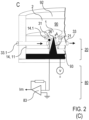
- Figure 2 shows a modified variant of the electrophysiological measuring device 100 in different phases of the relative movement of the cell sample 1 and the nanoelectrodes 21 (not an embodiment of the invention).
- the substrate 11 is formed by a substrate body 14, e.g. made of PDMS or polyvinyl chloride (PVC) with a thickness of 3 mm to 5 mm, with continuous suction openings 31, which extend in the z-direction perpendicular to the reference plane of the substrate 11.
- the suction openings 31 are, for example, round with a diameter, e.g. in the range of 1 to 4 ⁇ m.
- the chamber 90 is divided by the substrate 11 into an upper chamber section 92 and a lower chamber section 93, which are connected to one another via the suction openings 31.
- One of the suction openings 31 is shown with a schematically shown lateral suction line 33, which is connected to the pump device 32 (see Figure 2A ).
- each of the suction openings 31 can be equipped with a lateral suction line 33 and/or At least one suction line can be connected to the lower chamber section 93.
- a perfusion line 33.1 can be provided at at least one of the suction openings 31, as shown schematically in Figure 2C shown.
- the suction opening 31 can optionally be covered with an ultra-thin elastic film (e.g. made of silicone), as in Figure 3
- an ultra-thin elastic film e.g. made of silicone
- the nanoelectrodes 21 of the electrode device 20 are arranged in a fixed position in the lower chamber section 93.
- the nanoelectrodes 21 extend in the z-direction through the suction openings 31.
- the nanoelectrodes 21 are arranged sunk in the suction openings 31.
- the nanoelectrodes 21 are preferably positioned centrally in the suction openings 31.
- the electrode carrier 22 of the nanoelectrodes 21 is, as described above with reference to Figure 1 described, divided into individual carrier sections 25 by insulation sections 24. Each of the carrier sections 21 is electrically connected to a measuring circuit 81 of the measuring device 80.
- the cultivation medium 2 is drawn, in particular, from the upper chamber section 92 through the suction openings 31. Together with the resulting liquid movement, individual cells or cell groups of the cell sample 1 are drawn to the suction openings 31.
- the cell sample 1 is partially drawn into the suction opening 31 when the suction line 33 is subjected to the negative pressure, as shown schematically in the Figures 2B and 2C is shown.
- the cell sample 1 hits the electrode tip 26 of the nanoelectrode 21. Under the effect of the suction pressure, the cell sample 1 penetrates the nanoelectrode 21. Electrical measurement values are then recorded on the cell sample 1.
- the measuring device 100 according to Figure 2 can be implemented in a modified manner according to one or more of the following features.
- Several nanoelectrodes 21 can be provided per suction opening 31.
- the suction openings 31 can have a different shape, e.g. as a groove in the substrate body.
- the suction openings 31 can be closed at the bottom in the substrate body and each can be equipped with a lateral suction line, with the nanoelectrodes being firmly embedded in the substrate body. Coatings of the Nanoelectrodes and/or the culture area formed by the surface of the substrate 11.
- FIGS. 2A and 2B show an application of the measuring device for exclusive membrane potential measurements with a reference electrode 82 in the bath (cultivation medium 2).
- Figure 2C shows a modified application of the measuring device for patch-clamp measurements with a fixed cell ("cell attached" measurement) with a ground electrode 82.1 in liquid contact with the lower chamber section 93.
- adhesion sections 14.1 on the upper end of the suction openings 31 on the substrate 11, which end faces the upper chamber section 92.
- the adhesion sections 14.1 (shown schematically hatched) surround the upper edge of a suction opening 31.
- Adhesion sections 14.1 can also be provided in the variants according to the Figures 2A and 2B (not embodiments of the invention) and may be provided in the embodiments of the invention.
- a high-resistance contact > 100 megaohms or a giga-seal is formed at the edge of the suction openings 31. This is used to carry out the cell-attached measurement on the cell membrane surrounding the nanoelectrode 21 with respect to the membrane potential measured with the nanoelectrode 21.
- Both lines for potential (V) and membrane current (Im) are isolated from each other and can be measured simultaneously with the measuring device 80, which comprises a patch-clamp amplifier 83.
- the at least one nanoelectrode 21 has a central position in the suction opening 31, which is also referred to as a perfusion pore.
- the suction opening 31 simultaneously forms a perfusable compartment around the respective at least one nanoelectrode 21.
- the ground electrode 82.1 is arranged in this compartment, electrically insulated from the nanoelectrode 21, to form an additional virtual mass.
- the ground electrode 82.1 is also used for the "cell attached" patch-clamp measurements.
- FIG. 2C illustrates a further advantageous feature of a measuring device (not an embodiment of the invention) which in the variant of the Figure 2C and can also be optionally provided in the described embodiments.
- the nanoelectrode 21 has a tip distance A from the surface of the substrate (distance of the electrode tip in the longitudinal direction of the nanoelectrode 21 from the surface, see arrow).
- the tip distance A is preferably selected in the range from 100 nm to 5 ⁇ m.
- the diameter of the suction opening 31 is preferably selected in the range from 1.5 ⁇ m to 5 ⁇ m for measurements on individual cells and in the range from 10 ⁇ m to 100 ⁇ m, in particular 10 ⁇ m to 20 ⁇ m, for measurements on cell aggregates.
- the in Figure 3 The variant of the electrophysiological measuring device 100 shown is similar to the measuring device 100 according to Figure 1 constructed (not an embodiment of the invention).
- the substrate device 10 forms with the chamber 90 a vessel for receiving the culture medium 2 with the cell sample 1.
- the substrate device 10 is equipped with a flexible, deformable carrier membrane 12, which is intended for receiving the cell sample 1 and optionally for the growth of the cells of the cell sample 1.
- the carrier membrane 12 divides the chamber 90 into an upper chamber section 92 and a lower chamber section 93.
- the carrier membrane 12 is, for example, a silicone membrane, for example with a thickness in the range of 1 to 5 ⁇ m.
- the carrier membrane advantageously also acts as an insulator by tightly enclosing the shaft of the nanoelectrode. This enables the optional use of nanoelectrodes not coated with an insulation layer 23.
- the shaft of the nanoelectrode can be extended for this application, e.g. to up to 50 ⁇ m.
- the electrode device 20 is formed by stationary nanoelectrodes 21 in conjunction with a flat electrode carrier 22 at the bottom of the chamber 90.
- the electrode device 20 forms a bottom part with which the chamber 90 is closed at the bottom.
- the carrier membrane 12 is stretched between the walls 91 of the chamber 90 so that it extends parallel to the extension of the electrode carrier 22.
- the carrier membrane 12 can be arranged at a distance from the electrode tips 26 of the nanoelectrodes 21 or can touch them.
- the actuating device for the relative movement of the cell sample 1 and the nanoelectrodes 21 comprises the suction device 30 with the at least one suction opening 31 in the bottom part of the substrate 11 and a pumping device 32 connected to the suction opening 31.
- a negative pressure liquid is sucked out of the lower chamber section 93, so that the carrier membrane 12 with the cell sample 1 is moved to the electrode device 20 and in particular to the nanoelectrodes 21.
- the nanoelectrodes 21 penetrate the carrier membrane 12 and the cell membrane 1A of the cells of the cell sample 1 located on the carrier membrane 12 until the electrode tips 26 are positioned inside the cells. The desired electrophysiological measurement is then carried out.
- the carrier membrane 12 is provided by a separating device which separates the space for receiving the cell sample 1 (upper chamber section 92) from the nanoelectrodes 21 in the lower chamber section 93 as long as the suction device 30 is not actuated and the carrier membrane 12 is not pulled towards the nanoelectrodes 21.
- the measuring device 100 according to the Figures 1 to 3 can be manufactured from plastic, metallic components and/or ceramics using available manufacturing processes in fluidic microsystem technology.
- the substrate device 10 of the electrophysiological measuring device 100 is formed by the mouth region 13A of a suction tube device (not an embodiment of the invention).
- the suction tube device is, for example, a measuring pipette 13 (partially shown) which is designed for a patch-clamp measurement (patch-clamp pipette).
- the edge of the mouth region 13A (pipette tip) at the end of the measuring pipette 13 preferably has a thickness d in the range of, for example, 1 ⁇ m to 10 ⁇ m.
- the edge of the mouth region 13A has an adhesive surface coating to support the formation of the seal resistance.
- the inner diameter D of the mouth region 13A is in the range of, for example. B.
- the electrode device 20 comprises two or more nanoelectrodes 21 (one of the electrodes shown in a sectional view for illustration purposes), which are arranged protruding on the peripheral edge of the mouth region 13A.
- the longitudinal directions of the nanoelectrodes 21 extend parallel to the axial direction of the measuring pipette 13.
- Connecting lines 27 run from the nanoelectrodes 21 to measuring circuits 81 of a measuring device 80.
- the connecting lines 27 are attached outside the mouth opening, for example on the outer surface of the measuring pipette 13, and are electrically insulated relative to the environment ( Figures 4A and 4B ) or free-standing ( Figure 4C ).
- the measuring device 80 additionally comprises a reference electrode 82, which is arranged inside the measuring pipette, and a measuring amplifier 83, which is designed for measuring ion currents.
- the adjusting device for the relative movement of the cell sample 1 ( Figure 4B, 4C and 4D ) and the nanoelectrodes 21 a suction device 30.
- This is in the variant according to Figure 4 formed by the mouth opening 34 of the suction tube device (mouth of the measuring pipette) and a pump device connected to the suction tube device (piston of the pipette, not shown).
- the mouth region 13A forms the suction opening, on the edge of which the nanoelectrodes 21 are arranged.
- the nanoelectrodes 21 may carry an insulating layer 23 which covers the nanoelectrodes 21, leaving the electrode tips 26 uncoated ( Figure 4B ).
- the electrode tips 26 protrude, for example, approximately 100 nm to 5 ⁇ m from the insulation layer 23.
- the insulation layer 23 can improve the contact with the cell membrane, which is advantageous for both individual cells and cell aggregates.
- the insulation layer 23, e.g. made of SiO 2 is intended for mouth openings 34 with an inner diameter, e.g. in the range of 10 to 100 ⁇ m, and for measurements on cell aggregates that are connected via nexus connections.
- No insulation layer 23 is required, for example, if so-called "cell-attached” measurements are carried out on individual cells and a high-resistance contact (> 100 megaohms) or a giga-seal is formed at the edge of the mouth area 13A ( Figures 4C and 4D ). This would be the case, for example, for an inner diameter D of the orifice 34 in the range of 1 to 30 ⁇ m, a thickness in the range of 2 to 5 ⁇ m and the suction of a single cell.
- a cell suspension is provided in a vessel (not shown) which contains the cells or cell aggregates to be examined.
- the measuring pipette is introduced into the cell suspension.
- a cell or a cell aggregate is sucked into the mouth area 13A (cell-attached configuration), whereby the cell is moved to the nanoelectrodes 21 until they penetrate into the cell interior and establish electrical contact with the cytosol in the cell.
- the membrane patch 1B is formed (see Figures 4B, 4C ).
- the electrophysiological measurement such as a patch-clamp measurement, is carried out in a known manner.
- membrane potentials are measured on different cells that are connected to each other by nexus contacts, for example in myocardial cell samples.
- several potentials of different cells can be measured and used as reference values for "cell-attached" measurements.
- a particular advantage of the Figure 4 The advantage of the measuring device shown is that, due to the positioning of the nanoelectrodes 21 at the mouth area 13A, no further reference electrode needs to be contained in the vessel with the cell suspension.
- the measuring pipette 13 can be handled freely. This is particularly advantageous when changing solutions for testing substances or the like.
- the intracellular potential (V) can be tapped directly and used as a reference value for the patch clamp measurement. In the cell-attached configuration, ion currents through the insulating membrane section and, at the same time, the action potentials generated by the cell aggregate or the individual cell can be measured.
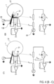
- FIG. 4B a schematic representation of the current flow, starting from the "virtual ground” (IV converter, black dot in pipette) through the membrane patch of the cell membrane 1A, the nanoelectrode 21, an external conductive (e.g. gold) metal jacket 13B, which surrounds the measuring pipette 13, through to the voltage generator 84, which generates a voltage clamp signal.
- the bath solution is not connected to the measuring device 80 (patch-clamp amplifier).
- such measurements can be carried out under conditions of gigaseal isolation (hatched areas on pipette tip) of the membrane patch.
- an insulation layer 23 e.g. SiO 2
- the membrane patch is isolated from the remaining cell membrane 1A and bath solution by contact with the pipette tip.
- the voltage clamp signal is applied to the virtual earth via the nanoelectrode (R NE ), with the gigaseal resistor (RGig) isolating the membrane patch from the bath solution.
- the pipette is provided on the outside with two conductor tracks that are insulated from one another and run from the measuring device 80 directly to the pipette tip (patch pore).
- Two nanoelectrodes 21.1, 21.2 are provided on the pipette tip, which contact the (-) input and the output of an operational amplifier of the measuring circuit 81 for 2 electrode voltage clamp via the two conductor tracks.
- the cell membrane potential is measured at the cell sample 1 in the form of a cell aggregate is measured and a feedback current is injected via the nanoelectrode 21.2 to keep the membrane potential constant.
- the bath solution is not connected to a separate earth potential.
- the measuring device 80 also comprises the measuring amplifier 83 for measuring ion currents, in particular for a patch-clamp current measurement, which is connected to a reference electrode 82 inside the pipette.
- the myocardial cells of the cell aggregate are connected to each other by nexus contacts, the potential of the cells sucked into the patch pore is kept constant.
- the ion currents on the "clamped" membrane patch are measured with the current-voltage converter.
- the inner diameter of the pipette tip is between 10 and 200 ⁇ m.
- the variant of the measuring device shown comprises a multiple coating of the glass surface of the measuring pipette 13 with a layer sequence which comprises a structured gold layer produced by sputtering on the glass surface with a thickness in the range of 100 nm to 500 nm for forming the conductor tracks and on top of that a SiO 2 layer with a thickness in the range of 50 nm to 500 nm.
- the nanoelectrodes 21.1, 21.2 are arranged by placing them, for example, on the gold layer at the mouth opening.
- FIGS 5 to 6 illustrate further modifications of the electrophysiological measuring device 100 (not embodiments of the invention) and Figure 7 illustrates an embodiment of the electrophysiological measuring device 100 according to the invention), each with a substrate device 10, an electrode device 20, comprising an electrode carrier 22 and nanoelectrodes 21, and a suction device 30 in a schematic sectional view ( Figures 5 , 7 ) or schematic plan view ( Figure 6 ).
- a chamber 90 with a conical shape narrowing towards the substrate 11 is provided above the substrate device 10.
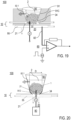
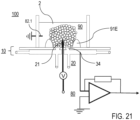
- the chamber 90 is designed to accommodate a culture medium 2 and the cell sample 1 in the form of a cell aggregate (see Figure 5, not an embodiment of the invention). Further variants of this embodiment are described below with reference to the Figures 19 (embodiment of the invention) and 20 to 21 (not embodiments of the invention).
- the chamber wall of chamber 90 has according to Figure 5 an upper, flatter wall section 91A and a lower, steeper wall section 91B (not an embodiment of the invention).
- This Subdivision can have advantages when fixing the cell sample 1 in the chamber 90.
- the lower, steeper section 91B can be provided with an inner, electrically conductive coating, which forms a reference electrode 85 for an electrophysiological measurement or serves for impedance measurements to detect movements of the cell aggregates.
- the substrate device 10 comprises a substrate 11 which, as in Figure 1 by the electrode carrier 22 with electrically conductive carrier sections 25 and insulation sections 24 (see Figure 6 , not an embodiment of the invention).
- the insulation sections 24 divide the electrode carrier 22 into the carrier sections 25, which are each connected to a nanoelectrode 21 and a measuring circuit 81 of the measuring device 80.
- the nanoelectrodes 21 have a height in the range of e.g. 1 to 10 ⁇ m.
- the measuring device 80 comprises the measuring circuits 81, which are each connected to the nanoelectrodes 21, and a measuring amplifier 83, which is designed for measuring ion currents, in particular a patch-clamp current measurement, and is connected to a reference electrode 82.
- the suction device 30 comprises a central suction opening 31 in the substrate 11, which is connected to a pump device (not shown) for applying a negative pressure.
- a ring opening 34 is provided, which surrounds the nanoelectrodes 21 in the reference plane of the substrate 11.
- the ring opening 34 can be connected to the same pump device or, as in Figure 5 shown, be connected to a separate pump device via a flow channel 35 below the electrode device 20.
- the outer ring opening 34 serves to suck in the cell sample 1 and fix it in the funnel of the chamber 90.
- the ring opening 34 can be replaced by several suction openings which are evenly distributed in a circle around the central suction opening 31.
- the embodiment of the invention according to Figure 7 is constructed similarly to the electrophysiological measuring device 100 according to Figure 5 .
- no ring opening is provided in the substrate 11.
- the chamber wall 91 forms a projection 91C at a distance from the substrate 11, which extends in the circumferential direction and radially inwards.
- the projection 91C forms an undercut, with which the fixation of the cell sample 1 on the substrate 11 with the nanoelectrodes 21 is additionally supported.
- a concentric suction channel is formed, which is provided with at least one flushing line 95.
- the cell sample 1 can be sucked into the chamber via this suction channel, which enables the fixation of the cell sample 1 as an alternative to the ring opening 34 according to Figure 5 and also enables perfusion of cell sample 1 with liquids, e.g. solutions of test substances.
- a cell aggregate that forms the cell sample 1 is first pipetted into a culture medium 2 in the chamber 90.
- the suction opening 31 and/or the ring opening 34 and/or the flushing line 95 are subjected to a negative pressure, the cell sample 1 is drawn towards the bottom of the chamber 90 onto the nanoelectrodes 21 until they penetrate the cells of the cell sample 1.
- the cell sample 1 is in the variant according to Figure 5 from the lower, steeper wall section 91B of the chamber wall. Since the cells of the cell sample 1 are connected to each other via nexus contacts, the measuring device 80 can record electrical measured values that represent the entire cell sample 1 (see [16]).
- the cell sample is sucked in with the suction opening 31 in the center and the optionally provided concentric ring opening 34 or the concentric suction channel in the lower funnel section, so that the penetration of the membrane is effected.
- the suction opening 31 is preferably surrounded by a sealing ring section 28, which forms an electrical resistance as in conventional patch clamp measurements.
- the sealing ring section 28 is formed by the surface of an insulation section 24.
- the actuating device is formed by an electrode drive device 40, as shown schematically in the Figures 8 to 11 is shown (no embodiments of the invention).
- the electrode drive device 40 comprises a mechanical drive that acts on the electrode device 20, in particular the electrode carrier 22 and/or the nanoelectrodes 21.
- the electrode drive device 40 comprises an electrically stimulated piezo actuator made of a piezoelectric material, such as piezoelectric ceramics or piezoelectric crystals. Alternatively, other materials can be used that change their geometric properties in response to another, e.g. optical, external stimulation.
- the electrode carrier 22 with the nanoelectrodes 21 is arranged to be movable relative to the chamber wall 91 of the chamber 90, wherein between the electrode device 20 and the chamber wall 91, preferably a seal 91D which allows a sliding movement of the electrode carrier 22 and is at the same time liquid-tight.
- the substrate device 10 comprises a substrate 11 which has a substrate body 14 and/or a pore membrane 16, each of which contains continuous electrode openings 15.
- the electrode carrier 22 of the electrode device 20 is arranged on the underside of the substrate device 10. Nanoelectrodes 21 of the electrode device 20 protrude into the electrode openings 15 towards the chamber 90. When the electrode drive device 40 is actuated, the nanoelectrodes 21 are pushed forward through the electrode openings 15.
- the substrate body 14 is made of a compressible material, such as PVC with a thickness of 100 nm to 100 ⁇ m.
- the pore membrane 16 is arranged on the upper side of the substrate body 14 facing away from the electrode device 20.
- the pore membrane 16 is made of an inelastic material, such as PDMS or PVC with a thickness of 100 to 500 ⁇ m and is attached to the inside of the chamber wall 91.
- the pore membrane 16 is shown at a distance from the substrate body 14.
- the pore membrane 16 which extends parallel to the reference plane of the substrate 11 with the substrate body 14, touches the upper side of the substrate body 14.
- the pore membrane 16 represents a fixed support for the cell sample 1 ( Figure 8A).
- the electrode drive device 40 When the electrode drive device 40 is actuated, the electrode device 20 presses against the substrate body 14, whereby the latter is compressed between the electrode device 20 and the pore membrane 16, while the nanoelectrodes 21 are pushed forward through the electrode openings 15 until the electrode tips 26 penetrate into the cell sample 1 ( Figure 8B). In this state, the desired electrical quantities of the cell sample 1 are measured with the measuring device 80.
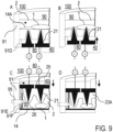
- the at least one electrode opening 15 of the substrate device 10 is closed with a cover membrane 14A and the electrode drive device 40 is set up for the movement of the nanoelectrodes 21 through the cover membrane 14A into the cell sample 1 ( Figures 9A and 9B , not embodiments of the invention).
- the electrode carrier 22 with the nanoelectrodes 21 is movable relative to the chamber wall 91 of the chamber 90 arranged, whereby the liquid-tight seal 91D allows the sliding movement of the electrode carrier 22.
- the cover membrane 14A forms the substrate surface for receiving the cell sample 1, and it is like the pore membrane 16 ( Figure 8 ) is made of an inelastic material and is attached to the inside of the chamber wall 91.
- the cover membrane 14A is provided by a separating device which separates the space for receiving the cell sample 1 (interior of the chamber 90) from the nanoelectrodes 21 as long as the electrode driving device 40 is not actuated and the nanoelectrodes 21 are not advanced.
- the substrate 11 of the substrate device 10 comprises a substrate body 14 with a closed surface, in which case nanoelectrodes 21 of the electrode device 20 are arranged at a distance from the substrate body 14 and protrude from the chamber 90 to the substrate body 14 (top-down configuration, see Figures 9C and 9D , not embodiments of the invention).
- the electrode device 20 is connected to the chamber wall 91 and can be moved perpendicular to the reference plane of the substrate 11.
- the electrode drive device 40 is actuated, the nanoelectrodes 21 are advanced towards the substrate 11 until the electrode tips 26 penetrate into the cell sample 1, so that the measurement of the desired electrical quantities of the cell sample 1 can be carried out with the measuring device 80.
- the substrate body 14 can comprise a transparent plate, e.g. made of plastic or glass, so that a visual and/or optical-microscopic observation of the cell sample 1 is possible through the substrate body 14.
- the substrate body 14 is coated with a cell-compatible material, such as Magel, poly-L-lysine, gelatin or fibronectin.
- a lateral flushing line 95 (perfusion channel), which is also optionally provided, serves to supply cells. Furthermore, the flushing line 95 allows the generation of a negative pressure, under the effect of which the advance movement of the electrode device 20 is supported.
- a spacer 91E (elastic spacer element, shown hatched), e.g. made of PDMS or rubber, is provided, which seals the chamber and is also equipped with at least one stop element 91F (not an embodiment of the invention).
- the spacer 91E can be attached to the edge of the chamber 90 (as shown) and optionally additionally provided in the volume of the chamber, surrounding the nanoelectrodes 21. Spacers 91E can thus be placed not only at the edge of the chamber 90, but also between the nanoelectrodes 21 and the substrate body 14.
- a simultaneous movement of the nanoelectrodes 21 into several cells on a substrate surface is made possible without the electrode carrier 25 being bent by the movement.
- the movement of the nanoelectrodes 21 can be restricted with the at least one stop element 91F (limiting element), which enables a defined penetration depth of the nanoelectrodes 21 into the cytosol to be set.
- the solid SiO 2 coating of the nanoelectrodes 21 can be omitted.
- a coating 23A of the nanoelectrodes 21 with a thin layer (e.g. 10 nm to 100 nm or more, e.g. up to 1 ⁇ m) of a viscous material for example Vaseline, mixtures of silicone oil and Parafilm, polydimethylsiloxane (PDMS), gelatin, each with admixtures of extracellular matrix (Magel, BioCoat, fibronectin, poly-L-lysine or amino acids and nutrients, is preferably provided.
- the coating 23A is partially stripped off the nanoelectrodes 21 so that contact with the cytosol is established (see Figure 9D , not embodiments of the invention).
- the coating 23A of the nanoelectrodes 21 with the viscous material can also be provided in the other embodiments of the invention.
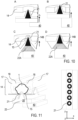
- the substrate of the substrate device 10 comprises a substrate body 14 with electrode openings 15 made of a non-compressible material ( Figures 10, 11 , not embodiments of the invention).
- the electrode device 20 is as in Figure 8 arranged below the substrate body 14, with the nanoelectrodes 21 protruding into the electrode openings 15. Deviating from Figure 8 the electrode device 20 is arranged at a distance z 0 from the substrate body 14. The distance z 0 is selected such that the nanoelectrodes 21 can be moved by a sufficient feed path through the electrode openings 15 into the cell sample 1 ( Figures 10A/B ).
- the distance z 0 is, for example, 100 nm to 3 mm.
- the underside of the substrate body 14 forms a stop for the electrode device, so that a defined penetration depth of the nanoelectrodes 21 in the cell sample can be set.
- the substrate body or the cell array can be equipped with flexible spacers (spacer elements) and stop elements (see Figures 9C, 9D , not embodiments of the invention).
- the substrate body 14 can be provided on its underside with a guide cone 14B, which interacts with suitably shaped conical sections 22A of the electrode carrier 22 ( Figure 10C , not an embodiment of the invention).
- a guide cone 14B which interacts with suitably shaped conical sections 22A of the electrode carrier 22 ( Figure 10C , not an embodiment of the invention).
- the guide cone 14B can consist of a flexible material (eg PDMS), which has a sealing and insulating effect when the nanoelectrode moves.
- an insulating coating of the nanoelectrode can optionally be dispensed with ( Figure 10D , not an embodiment of the invention).
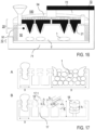
- Figure 11 shows a structured surface of the substrate body 14 with substrate projections 17 which have laterally protruding anchor elements 18.
- the substrate projections 17 with the anchor elements 18 fix the cell sample 1 during the piercing of the nanoelectrode 21 when this is pushed forward through the electrode opening 15 with the electrode drive device 40.
- the substrate projections 17 have an elongated wall shape so that a groove (channel) for receiving the cell sample 1 is formed between the substrate projections 17.
- the cell sample 1 can, for example, form a fiber growing in the longitudinal direction of the groove which is fixed in the channel by anchor elements.
- the upper surface of 17 is provided with nanostructures which prevent cell adhesion, and the groove can optionally be provided with adhesion-promoting coatings.
- the nanoelectrodes 21 and the electrode openings 15 are, for example, B. arranged in a row, as shown in the top view in the right part of Figure 11
- the peripheral edges of the electrode openings 15 each form sealing surfaces for supporting the cell membrane of the cell sample during the measurement. Further details and functions of the structured surface are described below with reference to the Figures 15 and 17 (not embodiments of the invention) are described.
- the actuating device is formed by a substrate drive device 50, as shown schematically by way of example in Figure 12
- the substrate drive device 50 comprises a mechanical drive which acts on the substrate device 10, in particular the substrate body 14 with the electrode openings 15.
- the electrode device 20 with the nanoelectrodes 21 and the electrode carrier 22, which e.g. as in Figure 1 is arranged in a stationary manner at the bottom of the chamber 90.
- the substrate drive device 50 is formed by the substrate body 14 itself, which is made, for example, from a material that can be stimulated electrically, optically, magnetically or with ultrasound. In response to an external stimulation, for example a change in an electrical voltage applied to the substrate body 14, the substrate body 14 contracts.
- the thickness of the substrate body 14 decreases ( Figures 12A/12B ) until the nanoelectrodes 21 protrude above the upper surface of the substrate body 14 and penetrate into the cell sample 1.
- the substrate body 14 preferably has a cell-compatible coating on its upper side, e.g. made of SiO 2 , which forms the substrate surface for receiving the cell sample.
- the actuating device is formed by a magnetic drive device 60, as shown schematically by way of example in Figure 13 is shown.
- the magnetic drive device 60 comprises magnetic particles 61 which are coupled to the cell sample 1 and a main magnet 62 which is arranged below the electrode device 20.
- the magnetic particles 61 are, for example, glass-coated micro iron spheres or magnetic nanoparticles.
- the main magnet 62 is a permanent magnet or a switchable electromagnet.
- the main magnet 62 is intended to draw the cell sample 1 to the nanoelectrodes 21 upon magnetic interaction with the magnetic particles 61 until they penetrate into the cells of the cell sample 1.
- the cell sample 1 can be moved in a direction perpendicular to the reference plane of the substrate 11 and optionally also laterally along the reference plane of the substrate 11. For the lateral movement, a displacement of the main magnet 62 parallel to the reference plane of the substrate 11 can be provided. Details of the movement of the cell sample 1 can be realized, for example, as described in [17].
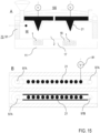
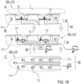
- the actuating device is formed by a chamber drive device 70, which is provided on a chamber wall 91 connected to the substrate device 10 and is designed to move the nanoelectrodes 21 towards the cell sample 1 (see Figures 14 to 16 ).
- the chamber drive device 70 is formed by the chamber wall 91 itself.
- the chamber drive device 70 can be a separate component which is connected to the chamber wall 91, e.g. made of an elastically deformable material, or another part of the chamber 90 and deforms the chamber wall 91 when actuated (see e.g. Figure 16 ).
- This variant is implemented as a top-down configuration, in which the electrode device 20 with the nanoelectrodes 21 is arranged at a distance above the stationary substrate 11 of the substrate device 10.
- the chamber wall 91 forms a Separation device is provided which separates the cell sample 1 inside the chamber 90 from the nanoelectrodes 21 as long as the chamber drive device 70 is not actuated and the nanoelectrodes 21 are not advanced ( Figures 14A , 15A and 16 ).
- the chamber 90 of the electrophysiological measuring device 100 is limited at the bottom by the substrate 11, e.g. made of glass, laterally by the chamber wall 91 and at the top by a cover part 94, e.g. made of glass, into which the electrode device 20 and a feed funnel 96 are integrated.
- the electrode device 20 comprises an electrode carrier 22 which is divided by insulation sections 24 into carrier sections 25 each with a nanoelectrode 21, as described above. Each nanoelectrode 21 is connected to a measuring circuit 81 of the measuring device 80.
- the chamber wall 91 consists of a piezoelectric material which contracts when an electrical voltage changes. Alternatively, the chamber wall can consist of an elastic material which can be compressed by a chamber drive device.
- the measuring device 100 is filled with a cell suspension comprising the cell sample 1 and a culture medium 2 via the feed funnel 96.
- the internal dimensions and the inner surface of the feed funnel 96 and the chamber 90 can be formed such that the supply of the cell suspension is supported by capillary forces.
- the cell sample 1 adheres to the surface of the substrate 11 before the nanoelectrodes 21 move.
- the surface of the substrate 11 can, as described with reference to Figure 17 described, to promote adhesion (nanostructuring as adhesion aid).
- the nanoelectrodes 21 are at a distance from the cells of the cell sample 1 ( Figure 14A ).
- the electrode device 20 Upon electrical stimulation of the chamber drive device 70, ie the chamber wall 91, the electrode device 20 is lowered until the nanoelectrodes 21 penetrate the cells of the cell sample 1 ( Figure 14B ). In this state, at least one electrical measurement value is recorded on cell sample 1.
- the chamber 90 of the electrophysiological measuring device 100 may be a closed vessel with a cylindrical interior ( Figures 14A and 14B , not an embodiment of the invention).
- the chamber 90 can have a cuboid-shaped interior and in particular be formed as a flow system (channel), as in the plan view in Figure 14C
- the nanoelectrodes 21 in the cover part 94 can be, for example, an electrode array, in particular for measurements on cell layers (monolayers).
- Figure 14C further illustrates that the chamber 90 may be laterally sealed by a spacer 91E (not an embodiment of the invention).
- the Figures 15A and 15B show a modification of the electrophysiological measuring device 100 according to Figure 14 , wherein the substrate 11 has a structured surface with substrate projections 17 and lateral anchor elements 18 (not embodiments of the invention).
- the substrate projections 17 form straight grooves on the bottom of the chamber 90 in which the cell sample 1 is positioned in an adherent manner.
- the grooves have, for example, a width of 10 ⁇ m to 300 ⁇ m and a depth of 3 ⁇ m to 300 ⁇ m.
- the lateral anchor elements 18 have, for example, an extension parallel to the reference plane of the substrate of 100 nm to 100 ⁇ m.
- the adherent growth exclusively or predominantly in the grooves can be supported by an adhesion-promoting coating in the grooves. While cells without the anchor elements 18 may only adhere superficially in the grooves and detach from the substrate 11, especially when contracting cardiac muscle fibers form (see [14], [15]), the anchor elements 18 provide additional fixation of the cells.
- Figure 15B shows a top view of a variant of the electrophysiological measuring device 100 in which the nanoelectrodes 21 form two straight rows that run along the alignment of the grooves formed by the substrate protrusions 17 (not an embodiment of the invention).
- a measuring circuit 81 is provided on each of the nanoelectrodes 21 (only illustrated on one of the nanoelectrodes 21).
- a stimulation electrode 97A, 97B is provided for stimulation and excitation propagation in one direction along the row.
- the side accesses of the chamber are open.
- the chamber is arranged in a cell culture vessel, for example, and then placed in a laterally sealed perfusion device so that the chamber can be perfused along the depressions in the base (grooves with and without anchor elements).
- the open variant of the Figure 15 ensures access of larger volumes of culture medium in a cell culture vessel to the cells by diffusion.
- the volume is in the very flat closed version Fig. 14C limited by the low height.
- the variants in particular of the Figures 15A and 15B have the further particular advantage of enabling intracellular measurements of the propagation of an action potential across a cell culture, e.g. a fiber structure. This was possible with conventional techniques only use extracellular electrodes.
- the propagation of the action potential can be measured in particular as a function of the effect of a perfusion fluid.
- the perfusion fluid can contain, for example, biologically active substances, in particular drugs, whose effect on the cell sample 1 is to be recorded by the electrophysiological measurement.
- FIG 16 a modified variant of the chamber drive device 70 is shown, which comprises a holder 71 and a lever actuator 72 (not an embodiment of the invention).
- the chamber 90 with the substrate device 10 and the electrode device 20 is fixed in the holder 71.
- the cover part 94 with the electrode device 20 is arranged so as to be movable relative to the chamber wall 91.
- the lever actuator 72 acts on the cover part 94.
- the chamber wall 91 is made of an elastic (compressible) material.
- the lever actuator 72 comprises, for example, a piezoelectric material or alternatively a combination of two materials with different thermal expansion coefficients, for example a bi-metal composite.
- the bi-metal composite has the advantage of a larger feed path (e.g. up to 100 ⁇ m or more), compared to a piezoelectric material (e.g. up to 2 to 5 ⁇ m).
- the actuator 72 can be part of the electrode carrier 22 (not an embodiment of the invention).
- substrate projections 17 with lateral anchor elements 18 can be provided, as shown in Figures 17A and 17B (not embodiments of the invention).
- the substrate projections 17 with lateral anchor elements 18 can be provided in all embodiments of the invention described here that are equipped with an adjusting device.
- the substrate projections 17 with lateral anchor elements 18 can be provided in measuring devices that do not have an adjusting device and in which no targeted relative movement of the cell sample and nanoelectrodes is therefore provided (not embodiments of the invention).
- the substrate projections 17 with lateral anchor elements 18 can be provided in substrates, e.g. in the form of cover glasses with a structured surface, in which no nanoelectrodes are provided (not embodiments of the invention).
- the production of the Substrate protrusions with the anchor elements are produced, for example, using nanoimprint lithography technology.
- the improved fixation of the cell sample is advantageous because cells with poor adhesion could, for example, be flushed out of the chamber if shear forces occur in a perfusion fluid due to the solution flow.
- the Figures 17A and 17B show substrate projections 17 in column or wall form, which at their upper ends each have lateral anchor elements 18 one above the other (so-called double or triple T-profiles).
- the substrate projections 17 can form, for example, simple T-profiles or have more than three lateral anchor elements 18 one above the other.
- the double T-profiles are characterized by a distance X of the substrate projections 17, which is selected for the fixation of individual cells, for example, in the range from 300 nm to 10 ⁇ m and for the fixation of cell aggregates and fibers, for example, in the range from 30 ⁇ m to 1 mm.
- the double-T profiles are characterized by a height Z of the substrate projections 17 in the range of 500 nm to 1 mm, a width of the anchor elements x 1 in the range of 100 nm to 1 mm, an undercut depth of the anchor elements x 2 in the range of 100 nm to 100 ⁇ m, a thickness of the anchor elements z 1 in the range of 100 nm to 500 nm and a distance of the anchor elements z 2 in the range of 50 nm to 10 ⁇ m.
- the anchor elements can have different extensions parallel to the reference plane of the substrate, e.g. increasing towards the substrate (see Figure 17B ).
- dimension X3 is between 2% and 50% larger than X2, with another anchor element a dimension X4 could be 5-50% larger than X3.
- the top of the T-structures has a lower adhesion for cells than the other surfaces, which causes a preferential adhesion and growth of the cells at the bottom along the depression (groove).
- a nub 17.1, for example, to prevent adhesion is shown as an example in Figure 17B shown (not an embodiment of the invention).
- the arrays for fibers in T-structures enable the measurement of action potentials (APs) at different points along and thus the determination of the propagation speed or the intercellular resistance.
- APs action potentials
- the measurement is carried out on a structure aligned with the grooves, which facilitates these measurements due to the simplified geometry - compared to undirected growth in a monolayer.
- the substrate projections 17 can form elongated nano-grooves, which form, for example, adhesion elements for filopodia of individual cells or cell aggregates. Openings in which electrodes can be moved can be provided in the substrate between the substrate projections 17 (see, for example, Figure 11 , not an embodiment of the invention).
- depressions between substrate projections 17, e.g. with T-structures can have other geometric shapes in addition to a straight alignment (growth of simple longitudinal fiber directions), such as running cross-shaped, running circular and/or having tapers (not an embodiment of the invention).
- Figure 18 shows a variant of the electrophysiological measuring device 100, in which the substrate device 10, the electrode device 20 and parts, in particular the actuators, of the actuating device form a flexible measuring probe 110 (not an embodiment of the invention). It is in Figure 18 only the distal end of the measuring probe 110 is shown, which furthermore has a flexible shaft for insertion, e.g. through an endoscope, into a tissue and is equipped with at least one drive unit for controlling the actuators of the actuating device.
- the measuring probe 110 can be implemented with all variants of actuating devices described above, with reference here to a suction device 30 as an example.
- the measuring probe 110 is constructed, for example, from flexible polymer materials and metals. Furthermore, the measuring probe 110 can be equipped with all variants of measuring devices 80 described above, in particular measuring circuits, pulse generators, reference electrodes, ground electrodes and/or amplifiers.
- the measuring probe 110 for measuring membrane potentials and/or ion currents can be used for the detection of intracellular membrane potentials of individual neuronal cells and/or the measurement of transmembrane ion currents, e.g. in brain tissue under in vivo conditions.
- the use of such probes and their placement in brain tissue is described in e.g. in [20].
- a disadvantage of conventional probes is that only the surface potentials of neuron groups, but not the intracellular potentials of individual Cells or the currents through cell membranes are recorded. With the measuring probe 110, new applications of electrophysiological measuring devices and an extension of the method described in [20] are achieved.
- the measuring probe 110 is equipped with a plurality of measuring units (e.g. measuring units for intracellular measurements of membrane potentials or current measurements through membranes in the cell-attached configuration), which are essentially like the variants of the electrophysiological measuring device described above, in particular as in the Figures 1 , 3 , 4 , 8 and/or 9, (no embodiments of the invention).
- a probe body 111 of the measuring probe 110 which forms the substrate device 10, e.g. has a diameter of 1 to 3 mm and is made of a flexible polymer, cylindrical depressions are embedded, each of which is equipped with a nanoelectrode 21 and a suction opening 31.
- the nanoelectrodes 21 are connected to the measuring device 80 via electrical conductors.
- the suction openings 31 are each connected to a pump device (not shown) via a suction line.
- Each suction line can be equipped with a valve for selectively controlling individual measuring units.
- the depressions can be used for measuring intracellular membrane potentials with an ultra-thin membrane (in Figure 18A not shown) must be closed (see Figure 3 ).
- Other adjustment devices may be provided for the suction devices shown (see e.g. Figures 8 and 9 , not embodiments of the invention).
- the measuring probe 110 is inserted into the tissue to be examined through an endoscope or another hollow tube.
- the tissue is drawn to the measuring probe 110 so that the nanoelectrodes 21 penetrate into the cells.
- the nerve tissue or a membrane with the adhered nerve tissue
- the substrate device 10 and the electrode device 20 of the measuring probe 110 can be adapted as in the Figures 18B and 18C is shown (not an embodiment of the invention).
- the latter is equipped on its surface with ring-shaped attachments 31.1, which vary in their dimensions (inner diameter e.g.
- the ring-shaped attachments 31.1 (corresponding to the pipette tips of the embodiments described above) are made of glass or SiO 2 or a polymer such as PDMS, for example, and form a high-resistance contact or gigaseal contact with the cell accommodated.
- the ring-shaped attachments 31.1 are located in the cylindrical recesses, which are connected to one or more pumping devices by thin tubes (capillaries).
- Ring-shaped attachments 31.1 (not shown) can also be provided which surround the edges of the recesses on the surface of the probe body (not an embodiment of the invention).
- FIG 18B Features of a further variant of the measuring probe 110 are shown, in which the ring-shaped attachments 31.1 are equipped with at least one nanoelectrode 21 in the edge region (not an embodiment of the invention).
- the negative pressure is applied within the ring-shaped attachment 31.1, which leads to the production of a seal with the surface of the nerve tissue and at the same time causes the penetration of cells with the nanoelectrodes.
- Figure 18C shows a larger section of the measuring probe 110 in a schematic plan view with several measuring units for measuring membrane potentials (upper row) or ion currents with the cell-attached configuration and membrane potentials with the aid of nanoelectrodes (lower row).
- the lines to the measuring device 80 are guided inside the measuring probe 110.
- the suction lines or other drive elements for moving the nanoelectrodes are not shown.
- the Figure 19 illustrates a further variant of the embodiment of the electrophysiological measuring device 100 according to the invention.
- Figures 20 to 21 illustrate variants of the electrophysiological measuring device 100 (not embodiments of the invention).
- the measuring device 100 comprises in particular a substrate device 10, an electrode device 20 with a nanoelectrode 21, a suction device 30, a measuring device 80 with a ground electrode 82.1 and a chamber 90 for receiving a culture medium 2 and the cell sample 1 in the form of a cell aggregate in a schematic sectional view.
- annular gap 34A is provided in the chamber wall 91 at the lower end of the chamber 90, which forms an annular suction channel.
- the annular gap 34A has a larger outer diameter than the diameter of the lower End of the chamber 90.
- the chamber wall 91 thereby receives a projection 91C for further fixation of the cell sample 1 (see also Figure 7 ).
- the annular gap 34A is connected to a pumping device (not shown) with which the annular gap 34A can be subjected to a negative pressure relative to the pressure in the chamber 90.
- the annular gap 34A can be replaced by several suction openings which are evenly distributed in the chamber wall.
- the cell sample 1 When the annular gap 34A is subjected to negative pressure, the cell sample 1 is advantageously sucked in from the side (radially outwards and simultaneously towards the bottom of the chamber 90), which, due to the symmetrical arrangement of the annular gap 34A, causes a force to act towards the nanoelectrode 21 at the bottom of the chamber 90.
- the nanoelectrode is arranged at an angle of 90 degrees relative to the suction direction in the annular gap 34A, the nanoelectrode 21 penetrates reliably into the cell sample 1.
- the nanoelectrode 21 is arranged on the bottom of the chamber 90 to the side of the annular gap 34A and to the side of the additional perfusion opening provided in the middle. A cell membrane of the cell sample is thus supported by the cell carrier 10 in the immediate vicinity of the nanoelectrode 21. This can advantageously achieve stabilization of the cell membrane.
- the perfusion opening arranged centrally at the bottom of the chamber 90 is connected to a flushing line 95, which provides a perfusion channel for perfusing the cell sample 1 and/or a connection to a reference electrode 82 of the measuring device 80.
- the flushing line 95 is formed, for example, as a microfluidic channel in the cell carrier 10.
- Figure 20 shows a variant of the measuring device 100, in which the chamber 90 deviates from the conical shape, e.g. according to Figure 19 at its lower end has the shape of a spherical shell section 91D.
- This shape has the advantage that an undesirable deformation of the cell sample 1, e.g. by a projection 91C (see Figure 19 ) or by inner edges on the bottom of the chamber 90, so that injuries are avoided, especially on sensitive cell samples.
- the spherical shell section 91D is preferably dimensioned so that about a third to a half of the sucked-in cell sample 1 sits in the spherical shell section 91D.
- Cell samples 1 in the form of cell aggregates have, for example, a diameter in the range of 300 ⁇ m to 1 mm, so that the diameter D of the chamber 90 at the upper end of the spherical shell section 91D and the height of the spherical shell section 91D in the axial direction is preferably selected in the range 500 ⁇ m to 800 ⁇ m.
- a ring opening 34 is provided, which is connected to a pump device (not shown) via a flow channel 35 below the electrode device 20.
- the ring opening 34 serves to suck in the cell sample 1 and fix it in the chamber 90.
- a cylindrical chamber 90 can be provided, in the bottom of which the ring opening 34 is arranged for sucking in the cell sample 1. Furthermore, an annular bead 91D is provided on the bottom of the chamber 91, which protrudes upwards in the axial direction and laterally surrounds the ring opening. The annular bead 91D advantageously forms a positioning and suction aid when fixing the cell sample 1.
Landscapes
- Health & Medical Sciences (AREA)
- Engineering & Computer Science (AREA)
- Life Sciences & Earth Sciences (AREA)
- Biomedical Technology (AREA)
- Chemical & Material Sciences (AREA)
- Physics & Mathematics (AREA)
- Food Science & Technology (AREA)
- Biochemistry (AREA)
- Urology & Nephrology (AREA)
- Hematology (AREA)
- Biophysics (AREA)
- Medicinal Chemistry (AREA)
- Analytical Chemistry (AREA)
- Molecular Biology (AREA)
- General Health & Medical Sciences (AREA)
- General Physics & Mathematics (AREA)
- Immunology (AREA)
- Pathology (AREA)
- Apparatus Associated With Microorganisms And Enzymes (AREA)
- Investigating Or Analyzing Materials By The Use Of Electric Means (AREA)
Description
- Die Erfindung betrifft elektrophysiologische Messgeräte und elektrophysiologische Messverfahren zur Erfassung mindestens eines elektrischen Messwerts an einer biologischen Zellprobe, insbesondere ein Messgerät und ein Messverfahren zur Erfassung von einem Aktionspotential an mindestens einer Zellmembran der Zellprobe und/oder einem lonenstrom durch mindestens eine Zellmembran der Zellprobe. Es werden auch Substrate zur Aufnahme biologischer Zellen und deren Anwendungen beschrieben. Die Erfindung ist bei der Handhabung und insbesondere Charakterisierung von biologischen Zellproben, insbesondere von einzelnen Zellen oder Zellaggregaten, in der Pharmakologie, Medizin, Biochemie und/oder Biomedizin anwendbar.
- In der vorliegenden Beschreibung wird auf den folgenden Stand der Technik Bezug genommen, der den technischen Hintergrund der Erfindung darstellt:
- [1]
EP 1 040 349 B1 ; - [2] O. P. Hamill et al. in "Pflugers Arch." 1981 Aug; 391(2):85-100;
- [3]
EP 1 349 916 A2 ; - [4] J. Abbott et al. in "Acc. Chem. Res." 51 (2019) 600-608;
- [5] A. Cerea et al. in "Lab Chip" 18 (2018) 3492-3500;
- [6] X. Xie et al. in "ACS Nano" 9 (2015) 11667-11677;
- [7] X. Xie et al. in "ACS Nano" 7 (2013) 4351-4358;
- [8] K. Li et al. in "Comprehensive Biotechnology" Kapitel 5.11, S.125-139 (Elsevier B. V. 2011, DOI: 10.1016/B978-0-08-088504-9.00497-9);
- [9] M. R. Angle et al. in "Biophysical Journal" 107 (2014) 2091-2100;
- [10] "Nanostrukturierte Metallelektroden zur funktionalen Kopplung an neuronale Zellen", Dorothea Brüggemann, Dissertation, RWTH Aachen, Schriften des Forschungszentrums Jülich, Band 9, ISBN 978-3-89336-627-9;
- [11]
WO 2010/031506 A1 ; - [12] A. M. Shum et al. in "Adv. Mater." 29 (2017) 1602448;
- [13]
EP 1 953 812 A1 ; - [14] C. Morez et al. in "Biomaterials" 70, 94-104;
- [15] M. A. Bucaro et al. in " ACSNANO" 6 (2012), 6222-6230;
- [16]
DE 10 2017 130 518 ; - [17] R. Wang et al. in "Scientific reports" 8 (2018) Artikel-Nr.: 14205;
- [18] "Entwicklung eines autokontraktilen Herzmuskelmodells zur funktionalen Medikamenten-und Toxinforschung" Matthias Goßmann, Dissertation, Universität Duisburg-Essen, 2015, (https://duepublico2.uni-due.de/servlets/MCRFileNodeServlet/duepublico_ derivate_00040212/DissGossmann.pdf;
- [19] M. Goßmann et al. in "Cell. Physiol. Biochem." 2016; 38:1182 - 1198;
- [20] E. Musk et al. "An integrated brain-machine interface platform with thousands of channels" (http://dx.doi.org/10.1101/703801);
- [21]
DE 198 27 957 A1 ; - [22]
US 2006/0 163 062 A1 ; - [23] Y. I. Zilberter et al. in "Pflugers Arch." 1982 Aug, 394(2):150-5; und
- [24]
US 2006/129043 A1 . - Elektrophysiologische Untersuchungen an Zellproben aus mindestens einer biologischen Zelle oder Zellaggregaten umfassen insbesondere die Messung von lonenströmen durch die Zellmembran ("patch-clamp"-Messung) oder die Messung von Aktionspotentialen an der Zellmembran ("current-clamp"-Messung). Bei dem älteren "voltage-clamp"-Verfahren wird ein Kompensationsstrom in die Probe geleitet, um die Membranspannung konstant zu halten, wohingegen bei "patch-clamp"-Messungen wegen der geringen Stromamplituden auf die Injektion eines Kompensationsstromes während der Messung verzichtet werden kann. Es ist bekannt, elektrophysiologische Messungen an Pipettenspitzen oder mit planaren Messgeräten durchzuführen, bei denen eine einzelne Zelle oder ein rekonstituierte Membransystem auf einer Pore in einer ebenen Oberfläche ("patch-Pore") positioniert wird ([1], [2]). Es können mehrere Poren in einer Oberfläche vorhanden sein und somit mehrere Einzelzellen gleichzeitig mit der "patch-clamp" Technik ([2]) untersucht werden (Parallelisierung der Untersuchung). Die (Multiarray-)-"patch-clamp"-Methode bzw. "patch-clamp"-Chips werden z. B. in [1] und [3] beschrieben. Die Zellmembran einer einzelnen Zelle oder auch die Membranen mehrerer Zellen bilden bei den patch-clamp-Messungen eine feste Verbindung mit dem Rand einer Saugpore (auch als patch-Pore bezeichnet), die mit einer Saugvorrichtung verbunden ist. Am Rand der Saugpore wird der so genannte Sealwiderstand gebildet. Bei einer Variante der patch-clamp-Messungen, der so genannten "cell attached"-Messung" wird die Membran in der Pore nicht zerstört, sondern bleibt intakt (siehe [23]). Ein Nachteil dieser Messungen ist, dass das Membranpotential (im Gegensatz zur so genannten "whole cell"-Messung) nicht erfasst werden kann.
- Zur weiteren Parallelisierung von elektrophysiologischen Untersuchungen ist die Verwendung von Nanoelektroden-Arrays vorgeschlagen worden (siehe zum Beispiel [4] bis [8]). Ein Nanoelektroden-Array umfasst eine Vielzahl von kompakten ([4], [8]) oder hohlen ([5] bis [8]) Elektrodenspitzen mit typischen Durchmessern im sub-Mikrometer-Bereich, die zum Beispiel als Matrixanordnung von einem festen Substrat abstehen. Um eine intrazelluläre Messung (Messung im Zellinneren) durchzuführen, d.h. um einen direkten elektrischen Kontakt zwischen der Elektrode und dem Zytosol im Zellinneren herzustellen, müssen die Elektrodenspitzen die Zellmembran durchdringen (penetrieren). Andernfalls würde ohne ein Eindringen der Elektrodenspitzen in das Zellinnere das Zytosol von der Elektrodenspitze durch die Zellmembran isoliert werden, so dass praktisch nur eine extrazelluläre Messung (Messung an der Zellaußenseite) durchgeführt werden könnte. Die extrazelluläre Messung ist jedoch weniger aussagekräftig und wegen der relativ geringen Potentiale ungenauer als die intrazelluläre Messung.
- Die Penetration der Zellmembran kann spontan erfolgen oder durch eine Elektroporation induziert werden [4]. Die spontane Penetration hat die Nachteile, dass es sich um ein seltenes, nicht reproduzierbar realisiertes Ereignis handelt und die Elektrode oft nur unzureichend in die Zelle eindringt. Die Elektroporation hingegen kann mit einer unerwünschten Beeinflussung der Zelle und damit des Messergebnisses der elektrophysiologischen Untersuchung verbunden sein. Hohle Nanoelektroden der Nanoelektroden-Arrays aus [5] bis [8] erlauben neben einer elektrophysiologischen Messung oder sensorischen Aufgaben auch die Zufuhr von Biomolekülen in das Zellinnere. Neben den genannten Nachteilen hinsichtlich des Eindringens der Elektroden in die Zellen haben die hohlen Nanoelektroden weitere Nachteile aufgrund der beschränkten Miniaturisierbarkeit und Komplexität des Substrataufbaus.
- Die Messung der Kraft, die zum Durchdringen der Zellmembran mit einer Nanoelektrode erforderlich ist, mittels Techniken der Atomkraftmikroskopie (AFM) wird in [9] beschrieben. Die untersuchte Elektrode wird auf einem biegsamen AFM-Träger angeordnet und mit diesem in eine Zelle eingeführt. Aus dieser Technik ergeben sich zwar Hinweise auf die Kräfte, die für die Penetration erforderlich sind. Für praktische, routinemäßige elektrophysiologische Untersuchungen wäre diese Technik jedoch ungeeignet, da sie auf die Anwendung der AFM-Technik und auf Messungen mit einzelnen Elektroden beschränkt ist.
- Weitere Anwendungen von Nanoelektroden-Arrays sind in [10] und [11] beschrieben. Gemäß [10] werden mit nanostrukturierten Metallelektroden extrazelluläre Signale von biologischen Zellen abgeleitet. Die nanostrukturierten Metallelektroden sind für intrazelluläre Messungen ungeeignet. In [11] wird vorgeschlagen, elektrophysiologische Potentiale zur Erzeugung elektrischer Ströme auszunutzen. Um ein Eindringen der Nanoelektroden in die Zellen zu fördern, sind die Spitzen der Nanoelektroden mit einer Beschichtung versehen, die eine Endozytose der Membran aktiviert und damit die Aufnahme der Elektroden in den Innenraum der Zellen erleichtert. Diese Technik ist für elektrophysiologische Untersuchungen ungeeignet, da die Endozytose-Beschichtung die Zellen in unerwünschter Weise beeinflussen kann.
- Ein weiterer Nachteil herkömmlicher Nanoelektroden-Arrays kann sich durch eine natürliche Zellbewegung ergeben, die adhärente biologische Zellen aufgrund einer laufenden Umordnung ihrer Zell-Substrat-Kontakte ausführen können. Zellen können während der Messung über ein Substrat mit Nanoelektroden wandern, wodurch das Messergebnis verfälscht wird. Die natürliche Zellbewegung kann durch eine Adhäsions-mindernde Substratbeschichtung eingeschränkt werden. Die Substratbeschichtung hat jedoch den Nachteil, dass sie die Physiologie der Zellen beeinflussen kann.
- Das Interesse an einer Parallelisierung der Untersuchung von Zellen besteht nicht nur, um die Zahl der gleichzeitigen Messungen zu erhöhen. Vielmehr können bei der Anordnung einer Vielzahl biologischer Zellen auf einem Substrat mit einer strukturierten Oberfläche physiologische Bedingungen, wie zum Beispiel in einem Gewebe, nachgebildet werden. Strukturierte Substrate zur Aufnahme einer Vielzahl biologischer Zellen, wie sie zum Beispiel in [12] beschrieben sind, erlauben die Beobachtung von biochemisch induzierten Zellveränderungen und deren Übertragung von Zelle zu Zelle. Auch in diesem Fall sollen Zellbewegungen möglichst unterbunden werden, was bei den aus [12] bekannten Substraten nur ungenügend möglich ist. In [13] sind deformierbare Substrate beschrieben, die biologische Zellen aufnehmen können, aber nur für mechanische Verschiebungen biologischer Zellenproben geeignet wären. Aus [14] und [15] sind strukturierte Substrate mit so genannten Microgrooves bekannt, welche die Kultivierung adhärenter Zellen beeinflussen sollen, in der Praxis aber eine beschränkte Wirksamkeit haben können. Generell kann auch von Nachteil sein, wenn herkömmliche Substrate Beschichtungen, wie z.B. Matrigel oder Fibronektin, tragen, die an Zellen unerwünschte biochemische Veränderungen hervorrufen können.
- Weitere elektrophysiologische Untersuchungen an biologischen Zellen werden in [21] und [22] beschrieben, wobei die Zellen mit einem Unterdruck an Elektroden mit typischen Durchmessern im mm- oder µm-Bereich gesaugt und gehaltert werden. In [21] wird die Verwendung einer Mikroelektrode mit einem Durchmesser oberhalb 10 µm vorgeschlagen, die mittig im Inneren eines zylindrischen Elektrodenmantels sitzt, in dem ein Unterdruck erzeugt wird und der eine Saugeinrichtung bildet. Gemäß [22] ist die Elektrode zentral in einer Saugöffnung und vor diese vorragend angeordnet. Diese Techniken können aufgrund der relativ großen Elektrodendurchmesser Nachteile sowohl in Bezug auf den Platzbedarf der Elektroden als auch hinsichtlich der elektrophysiologischen Signalableitung haben. Die Technik gemäß [21] hat beschränkte Anwendungen, da insbesondere cell attached-Messungen nicht möglich sind.
- Aus [24] ist ein elektrophysiologisches Messgerät bekannt, bei dem eine Zelle unter der Wirkung eines Saugdrucks auf einer Pore gehalten wird, in der eine spitzenförmige Elektrode angeordnet ist. Maßnahmen für eine stabile Halterung der Zelle auf der Pore sind in [24] nicht offenbart.
- Die Aufgabe der Erfindung ist es, ein verbessertes elektrophysiologisches Messgerät und/oder ein verbessertes elektrophysiologisches Messverfahren zur Erfassung mindestens eines elektrischen Messwerts an einer biologischen Zellprobe bereitzustellen, mit denen Nachteile und Beschränkungen herkömmlicher Techniken vermieden werden können. Die Erfindung soll insbesondere elektrophysiologische Untersuchungen mit erhöhter Genauigkeit, Reproduzierbarkeit und Zuverlässigkeit ermöglichen, für die intrazelluläre Messung an Zellen geeignet sein, routinemäßige Anwendungen erlauben und/oder einen erweiterten Anwendungsbereich haben. Gemäß einem weiteren Gesichtspunkt soll die Erfindung ein verbessertes elektrophysiologisches Messgerät und/ oder ein verbessertes elektrophysiologisches Messverfahren bereitstellen, wobei eine bessere Haftung von Zellen auf Substratoberflächen ermöglicht wird.
- Diese Aufgaben werden durch Vorrichtungen bzw. Verfahren mit den Merkmalen der unabhängigen Ansprüche gelöst. Vorteilhafte Ausführungsformen und Anwendungen der Erfindung ergeben sich aus den abhängigen Ansprüchen.
- Gemäß einem ersten allgemeinen Gesichtspunkt der Erfindung wird die obige Aufgabe durch ein elektrophysiologisches Messgerät gelöst, das zur Erfassung mindestens eines elektrischen Messwerts an einer biologischen Zellprobe eingerichtet ist. Das elektrophysiologische Messgerät umfasst eine Substrateinrichtung, die zur Aufnahme der Zellprobe eingerichtet ist. Die Zellprobe umfasst eine einzelne biologische Zelle oder eine Vielzahl von Zellen (z. B. Zellhaufen, Zellaggregat, oder Gewebeabschnitt, insbesondere Zellaggregat mit durch Nexuskontakte verbundenen Zellen). Die Substrateinrichtung weist ein Substrat mit einer Substratoberfläche zur adhärenten Positionierung von Zellen auf. Die Substratoberfläche hat vorzugsweise eine ebene Form, wodurch eine Bezugsebene (im Folgenden auch: x-y-Ebene) des Substrats aufgespannt wird, wobei die Substratoberfläche selbst eben oder mit Erhebungen und/oder Vertiefungen strukturiert sein kann.
- Des Weiteren ist die Substrateinrichtung zur Bereitstellung mindestens eines Flüssigkeitsfilms, vorzugsweise einer Flüssigkeitsschicht oder eines Flüssigkeitsbads, für eine Abdeckung der Zellen konfiguriert und hierzu vorzugsweise, jedoch nicht zwingend als Teil einer Kammer (Gefäß) gebildet. Die Kammer kann geschlossen (z. B. Schale) oder für einen Durchfluss eingerichtet sein (z. B. Kanal). Die Kammer kann oberhalb der Substrateinrichtung in einer Kammerwand einen Vorsprung zur Fixierung der Zellprobe aufweisen. Die Substrateinrichtung kann ein- oder mehrteilig sein und/oder zumindest teilweise durch Teile des Messgeräts gebildet werden, die für weitere Funktionen neben der Aufnahme der Zellprobe konfiguriert sind. Die Substrateinrichtung umfasst insbesondere ein Substrat, das in verschiedenen Konfigurationen einen einzigen Substratkörper zur Aufnahme der Zellprobe umfasst oder mit weiteren Komponenten, wie z. B. Membranen, kombiniert sein kann. Das Substrat hat eine Substratoberfläche, die vorzugsweise aus einem zellverträglichen Material hergestellt ist und z. B. eine zellverträgliche Beschichtung trägt. Die Substratoberfläche, insbesondere die Beschichtung erfüllt vorteilhafterweise eine Doppelfunktion in Bezug auf die Isolation der leitenden Spitze von mindestens einer Nanoelektrode und den direkten dichten Kontakt mit der Zellmembran.
- Das elektrophysiologische Messgerät umfasst des Weiteren eine Elektrodeneinrichtung mit mindestens einer, vorzugsweise einer Vielzahl von Nanoelektroden (insbesondere mindestens zwei Nanoelektroden). Die Elektrodeneinrichtung weist eine einzige oder eine Vielzahl von Nanoelektroden auf. Werden im Folgenden Merkmale unter Bezug auf mehrere Nanoelektroden beschrieben, so sind diese Merkmale vorzugsweise in gleicher Weise auch bei Varianten mit einer einzigen Nanoelektrode gegeben. Jede Nanoelektrode erstreckt sich gerade in einer Longitudinalrichtung (im Folgenden auch: z-Richtung) von einem Elektrodenträger zu einer freien Elektrodenspitze (freies Ende). Der Durchmesser der Nanoelektroden, insbesondere an deren freien Elektrodenspitze, die in die Zellprobe ragt, ist kleiner als 1 µm, vorzugsweise kleiner oder gleich 800 nm, z. B. kleiner oder gleich 500 nm, und/oder mindestens 50 nm. Die longitudinale Länge der Nanoelektroden beträgt vorzugsweise mindestens 100 nm, besonders bevorzugt mindestens 1 µm, und/ oder höchstens 10 µm, besonders bevorzugt höchstens 3 µm.
- Die Elektrodeneinrichtung und die Substrateinrichtung sind so angeordnet, dass die Nanoelektroden intrazellulär in die Zellprobe einführbar sind, wenn diese von der Substrateinrichtung aufgenommen ist. Die Nanoelektroden haben eine Konfiguration, dass sie in mindestens eine der Zellen der Zellprobe ragen können. Die Elektrodeneinrichtung und die Substrateinrichtung sind miteinander verbunden. Vorzugsweise sind die Nanoelektroden so angeordnet, dass die Longitudinalrichtung der Nanoelektroden senkrecht zu der Bezugsebene der Substratoberfläche verläuft. In mindestens einem Betriebszustand des Messgeräts sind die Nanoelektroden relativ zur Substratoberfläche so positioniert, dass die freien Elektrodenspitzen einen senkrechten Abstand von der Substratoberfläche haben, so dass die Nanoelektroden mit dem Zytosol im Zellinneren der Zellprobe auf der Substratoberfläche in direktem Kontakt sind. Der senkrechte Abstand von der Substratoberfläche beträgt vorzugsweise mindestens 1 µm und/oder höchstens 1 mm, kann aber auch im Bereich geringer als 1 µm gewählt sein. Die Nanoelektroden können auf einem Schaft aufsitzen und Säulen bilden oder sich konisch zu einer Spitze verjüngen. Der Schaft kann durch einen Zylinder oder Kegelstumpf mit einer Höhe von 1 µm bis 50 µm gebildet werden, auf den die Nanoelektroden aufgesetzt werden. Der Schaft kann jedoch auch höher sein.
- Vorzugsweise ist die Elektrodeneinrichtung des elektrophysiologischen Messgeräts mit einer Messeinrichtung koppelbar oder fest verbunden. Die Messeinrichtung ist konfiguriert, elektrische Größen, insbesondere Spannungen und/oder Ströme, an den Nanoelektroden zu erfassen und elektrophysiologische Messwerte, wie z. B. Ruhepotentiale, Aktionspotentiale oder lonenströme durch Zellmembranen zu ermitteln. Vorzugsweise erfolgt die Messung von lonenströmen durch die Zellmembran ("patch-clamp"-Messung) oder die Messung von Aktionspotentialen an der Zellmembran ("current-clamp"-Messung). Es werden auch gleichzeitige oder aufeinanderfolgende Messungen sowohl von Aktionspotentialen als auch von lonenströmen mit der cell-attached patch clamp-Methode an einer Zellprobe ermöglicht.
- Gemäß der Erfindung ist das elektrophysiologische Messgerät mit einer Stelleinrichtung ausgestattet, die für eine gegenseitige Bewegung der Nanoelektroden und/oder der Zellprobe entlang der Longitudinalrichtung der Nanoelektroden ausgelegt ist. Die gegenseitige Bewegung ist so gebildet, dass die Nanoelektroden in die Zellprobe eindringen können, wenn diese von der Substrateinrichtung aufgenommen ist. Die Stelleinrichtung wirkt auf die Nanoelektroden, insbesondere deren Elektrodenträger und/oder die Nanoelektroden selbst, und/oder die Substrateinrichtung, insbesondere das Substrat oder eine seitliche Kammerwand, so dass die Nanoelektroden zu der Zellprobe und/oder die Zellprobe zu den Nanoelektroden aktiv bewegt werden. Die Stelleinrichtung wirkt so, dass die Nanoelektroden gleichzeitig in die Zellprobe dringen. Die Relativbewegung erstreckt sich vorzugsweise über einen Weg im Bereich von 100 nm bis 5 mm.
- Vorteilhafterweise werden durch die Bereitstellung der Stelleinrichtung des elektrophysiologischen Messgeräts zahlreiche Beschränkungen der herkömmlichen Techniken überwunden. Die Nanoelektroden, insbesondere deren Elektrodenspitzen, werden gezielt in der biologischen Zellprobe platziert. Die Einführung der Nanoelektroden in das Zytosol wird durch die Betätigung der Stelleinrichtung ausgelöst. Die Messung ist nicht von spontanen oder durch Elektrodenbeschichtungen erfolgende oder ausgelöste Prozesse abhängig. Die Genauigkeit, Reproduzierbarkeit und Zuverlässigkeit der Messung wird durch die Positionierung der Nanoelektroden in der Zellprobe verbessert. Die Erfinder haben festgestellt, dass biologische Zellproben die gleichzeitige Einführung einer Vielzahl von Nanoelektroden mit einer Penetration der Zellmembran erlauben, ohne dass die Nanoelektroden beschädigt werden. Indem die Stelleinrichtung eine gegenseitige Bewegung der Nanoelektroden und/oder der Zellprobe entlang der Longitudinalrichtung der Nanoelektroden erlaubt, werden unerwünschte Lateralkräfte, welche Nanoelektroden verbiegen könnten, vermieden oder auf ein vernachlässigbares Maß reduziert. Die Erfinder haben des Weiteren festgestellt, dass die Zellmembran stabilisierend auf die Nanoelektroden wirkt, so dass diese von der Zellmembran in das Zytosol geführt werden.
- Gemäß einem zweiten allgemeinen Gesichtspunkt der Erfindung wird die obige Aufgabe durch ein elektrophysiologisches Messverfahren gelöst, bei dem mindestens ein elektrischer Messwert an einer biologischen Zellprobe intrazellulär erfasst wird. Das Messverfahren, das vorzugsweise mit dem elektrophysiologischen Messgerät gemäß dem ersten allgemeinen Gesichtspunkt der Erfindung ausgeführt wird, umfasst die folgenden Schritte. Zunächst wird die Zellprobe, umfassend eine einzelne Zelle oder eine Vielzahl von Zellen, auf einer Substrateinrichtung angeordnet. Die Anordnung der Zellprobe auf der Substrateinrichtung umfasst z. B. eine Positionierung einer Zellsuspension auf einem Substrat der Substrateinrichtung, optional gefolgt von einer Kultivierung der Zellprobe. Alternativ umfasst die Anordnung der Zellprobe eine Positionierung der Substrateinrichtung in einer Zellsuspension, gefolgt von einer Übertragung von mindestens einer Zelle auf die Substrateinrichtung. Anschließend oder bei der Übertragung der mindestens einen Zelle auf die Substrateinrichtung wird eine Vielzahl von Nanoelektroden einer Elektrodeneinrichtung so positioniert, dass die Nanoelektroden, insbesondere deren Elektrodenspitzen, intrazellulärer in die Zellprobe ragen. Die Nanoelektroden erstrecken sich parallel zueinander in einer Longitudinalrichtung und senkrecht zu einer Bezugsebene, welche eine laterale Ausdehnung der Substratoberfläche repräsentiert. Die Positionierung der Nanoelektroden umfasst gemäß der Erfindung eine Bewegung der Nanoelektroden und/oder der Zellprobe entlang der Longitudinalrichtung der Nanoelektroden mit einer Stelleinrichtung, bis die Nanoelektroden in die Zellprobe ragen und einen direkten elektrischen Kontakt mit dem Zellinneren bilden. Anschließend erfolgt die Messung des mindestens einen elektrischen Messwertes an der Zellprobe.
- Die Penetration von Zellen der Zellprobe kann bei Betätigung der Stelleinrichtung so ablaufen, dass die Nanoelektroden mit ihren Spitzen zunächst die Zellmembran kontaktieren und deformieren (Destabilisierung) und anschließend durch eine pulsförmige Vorwärtsbewegung in die Zellen eindringen. Die pulsförmige Vorwärtsbewegung kann durch eine geeignete Steuerung der Stelleinrichtung, insbesondere Steuerung des Aktors durch die Antriebseinheit, bereitgestellt werden.
- Die Bereitstellung der Stelleinrichtung bietet den Vorteil, dass die Zellprobe vor der Messung räumlich von den Nanoelektroden getrennt angeordnet sein kann. Es kann ein unbeabsichtigtes Eindringen der Nanoelektroden in die Zellen verhindert oder auf ein vernachlässigbares Maß vermindert werden. Teile des Messgeräts, insbesondere der Substrateinreichung und/oder der Stelleinrichtung bilden eine Trenneinrichtung, die zur räumlichen Trennung der Zellprobe von den Nanoelektroden vor Betrieb der Stelleinrichtung eingerichtet ist. Mit Betätigung der Stelleinrichtung wird ein zeitlicher Bezugspunkt für die elektrophysiologische Messung gesetzt, so dass diese insbesondere die Erfassung einer Zeitabhängigkeit von elektrophysiologischen Größen umfassen kann.
- Vorteilhafterweise sind eine Reihe von Varianten möglich, die Stelleinrichtung im erfindungsgemäßen elektrophysiologischen Messgerät zu realisieren, wie im Folgenden dargestellt wird.
- Gemäß der Erfindung umfasst die Stelleinrichtung als Aktor und Antriebseinheit eine Saugeinrichtung, die für ein Ziehen der Zellprobe zu den Nanoelektroden eingerichtet ist. Die Saugeinrichtung wird durch mindestens eine Saugöffnung und eine Pumpeinrichtung (Saugpumpe) gebildet, die über die mindestens eine Saugöffnung in der Substrateinrichtung mit dem Raum über der Substratoberfläche verbunden ist. Das Substrat ist mit der mindestens einen Nanoelektrode ausgestattet. Vorzugsweise sind die Nanoelektroden bei der ersten Ausführungsform auf dem Substrat fixiert, von dem Substrat vorragend oder in das Substrat versenkt angeordnet. Bei Beaufschlagung der mindestens einen Saugöffnung mit einem Unterdruck relativ zum umgebenden Atmosphärendruck mit der Pumpeinrichtung werden die Zellprobe und/oder eine umgebende Suspensionsflüssigkeit zum Substrat hin gezogen. Die mindestens eine Saugöffnung ist so gebildet, dass bei Beaufschlagung der mindestens einen Saugöffnung mit dem Unterdruck die Zellprobe zur Substratoberfläche und mit mindestens einer Richtungskomponente parallel zur Longitudinalrichtung der Nanoelektroden bewegt wird. Bei Berührung einer Nanoelektrode mit einer Zelle wird die Nanoelektrode durch die Saugbewegung in die Zelle geführt. Die erste Ausführungsform der Erfindung hat die besonderen Vorteile, dass das Messgerät einen einfachen Aufbau hat und die Stelleinrichtung einfach steuerbar ist. Die Leistung der Pumpeinrichtung ist vorzugsweise veränderlich und steuerbar, so dass ein vorbestimmter Ansaugvorgang ausgeführt werden kann, der eine zuverlässige Penetration der Membran der Zellprobe ermöglicht. Der Ansaugvorgang erfolgt beispielsweise derart, dass in einer ersten Phase mit einem geringeren Saugdruck eine langsamere Bewegung der Zellprobe bewirkt wird als in einer zweiten Phase mit einem höheren Saugdruck. Mit der Saugeinrichtung können Zellproben verschiedener Größe bewegt werden. Die Wegstrecke, die von der Zellprobe zurückgelegt wird, ist durch die Dauer des Betriebs der Pumpeinrichtung einstellbar. Mit der Saugeinrichtung sind auch nicht-adhärente Zellen im Raum oberhalb des Substrats erfassbar.
- Gemäß der Erfindung ist oberhalb der Substrateinrichtung eine Kammer mit einer Kammerwand mit einer sich zum Substrat hin verengenden Konusform vorgesehen, wobei die Kammer zur Aufnahme eines Kultivierungsmediums und der Zellprobe in Gestalt eines Zellaggregats eingerichtet ist, und oberhalb der Substrateinrichtung ist in der Kammerwand am unteren Ende der Kammer ein Vorsprung zur Fixierung der Zellprobe vorgesehen.
- Vorzugsweise sind bei der Erfindung die Nanoelektroden auf dem Substrat der Substrateinrichtung vorstehend angeordnet, wobei die mindestens eine Saugöffnung vorzugsweise unmittelbar benachbart zu den Nanoelektroden angeordnet ist. Mit anderen Worten, die Nanoelektroden sind außerhalb der mindestens einen Saugöffnung an deren Rand angeordnet (randständige Nanoelektroden). Vorzugsweise befinden sich die Nanoelektroden und die mindestens eine Saugöffnung in einer Ebene. Die Zellmembran einer Zellprobe wird nicht im Zentrum der Saugöffnung, sondern seitlich neben der Saugöffnung penetriert. Vorteilhafterweise wird durch die Anordnung am Rand der mindestens einen Saugöffnung die Bewegung der Zellprobe parallel zur Longitudinalrichtung der Nanoelektroden vereinfacht. Des Weiteren wird durch die Verwendung von randständigen Nanoelektroden die Herstellung des erfindungsgemäßen Messgeräts und insbesondere die Kontaktierung der Nanoelektroden vereinfacht.
- Vorteilhafterweise kann die mindestens eine Saugöffnung an ihrem Rand, wo sich die Nanoelektrode oder Nanoelektroden befinden, mit einer adhäsiven Oberfläche ausgestattet sein, welche die Zelladhäsion fördert. An der adhäsiven Oberfläche des Umfangsrandes wird mit der Zellprobe ein Sealwiderstand (insbesondere im hohen Mega- oder Giga-Ohm-Bereich) gebildet. Damit werden die gleichzeitigen oder aufeinanderfolgenden Messungen von Aktionspotentialen und von lonenströmen an einer Zellprobe mit der "cell-attached patch clamp"-Methode verbessert. Durch die Verwendung von randständigen Nanoelektroden werden Beschränkungen herkömmlicher "cell attached"-Messungen behoben, und das Membranpotential kann direkt bestimmt und für die simultane patch clamp-Messung an der Zellprobe verwendet werden.
- Besonders bevorzugt ist die mindestens eine Saugöffnung im Substrat zwischen den Nanoelektroden vorgesehen, so dass beim Ansaugen der Zellprobe die angrenzenden Nanoelektroden in die Zellprobe eindringen. Die Nanoelektroden können z. B. entlang eines Kreises um eine zentrale Saugöffnung angeordnet sein. Es ist beispielsweise eine Vielzahl von Saugöffnungen im Substrat zwischen den Positionen der Nanoelektroden vorgesehen. Ein weiterer Vorteil der Saugeinrichtung besteht darin, dass aus der fluidischen Mikrosystemtechnik Komponenten verfügbar sind, mit denen die Saugeinrichtung des elektrophysiologischen Messgeräts realisierbar ist.
- Gemäß einer vorteilhaften Variante kann die mindestens eine Nanoelektrode zu der mindestens einen Saugöffnung hin geneigt angeordnet sein. Die Neigung kann Vorteile für die zuverlässige und deformationsfreie Einführung der Nanoelektrode(n) in die Zellprobe haben.
- Vorzugsweise ist jede Nanoelektrode über eine Verbindungsleitung mit einer Messeinrichtung verbunden, wobei die Verbindungsleitung außerhalb der mindestens einen Saugöffnung angeordnet ist, an deren Rand die Nanoelektrode positioniert ist. Vorteilhafterweise wird damit der Aufbau des Messgeräts vereinfacht.
- Die Form der Saugöffnung kann vorteilhafterweise in Abhängigkeit von der konkreten Anwendung der Erfindung gewählt werden. Die Saugöffnung kann zum Beispiel eine Kreisform oder eine eckige Form haben. Alternativ kann die Saugöffnung eine lang gestreckte Schlitzform haben. Gemäß einer weiteren vorteilhaften Variante der Erfindung umfasst die Saugöffnung alternativ oder zusätzlich eine Ringöffnung, die in der Substrateinrichtung angeordnet und mit der Pumpeinrichtung verbunden ist. Die Ringöffnung ist so angeordnet, dass sie entlang der Bezugsebene des Substrats mindestens eine Gruppe der Nanoelektroden umgibt. Vorteilhafterweise bietet die Ringöffnung die Möglichkeit, im Raum über dem Substrat eine vereinheitlichte Strömung hin zu den Nanoelektroden zu bilden.
- Gemäß einer weiteren Abwandlung der Erfindung können die Nanoelektroden in mindestens einer der Saugöffnung(en) im Substrat angeordnet sein. Es kann mindestens eine Nanoelektrode in jeder Saugöffnung vorgesehen sein. In diesem Fall erstreckt sich beispielsweise jeweils in einer Saugöffnung eine einzelne Nanoelektrode oder mehrere Nanoelektroden mit der Longitudinalrichtung senkrecht zur Bezugsebene des Substrats. Bei Beaufschlagung der Saugöffnung mit einem Unterdruck wird die Zellprobe an die Saugöffnung gezogen, wobei die Elektrodenspitze in das Zellinnere der Zellprobe eindringt. Die Zellprobe kann teilweise in die Saugöffnung gezogen werden, wo das Eindringen der Nanoelektroden in die Zellprobe erfolgt. Die Positionierung der Nanoelektroden in mindestens einer der Saugöffnungen hat den besonderen Vorteil, dass die Nanoelektroden in den Saugöffnungen einen mechanischen Schutz erhalten. Des Weiteren wird die Bewegung der Zellprobe parallel zur Longitudinalrichtung der Nanoelektroden erleichtert.
- Vorzugsweise erstreckt sich die mindestens eine Nanoelektrode parallel zu einer Innenwand der Saugöffnung in der Substrateinrichtung. Die Innenwand erstreckt sich bevorzugt senkrecht zur Bezugsebene des Substrats. Vorteilhafterweise wird damit eine Stabilisierung der Nanoelektroden bei der Penetration von Zellen erzielt.
- Elektrodenspitzen der Nanoelektroden können über die Substratoberfläche vorragen oder in der Saugöffnung versenkt sein. Im letzteren Fall ist die mindestens eine Nanoelektrode so angeordnet ist, dass ihr freies Ende einen vorbestimmten senkrechten Abstand zur Oberfläche der Substrateinrichtung aufweist.
- Gemäß einer weiteren vorteilhaften Variante kann die mindestens eine Saugöffnung frei von Referenzelektroden für die intrazelluläre Erfassung des mindestens einen elektrischen Messwerts sein. Vorteilhafterweise ist für die erfindungsgemäß vorgesehene cell-attached-Messung keine Referenzelektrode erforderlich, da das intrazelluläre Potential der Zellprobe als Bezugspotential für die Messung verwendet werden kann.
- Die Saugeinrichtung kann bei den oben beschriebenen Varianten der Erfindung unmittelbar auf die Zellprobe wirken. Gemäß einer weiteren Abwandlung der ersten Ausführungsform kann die Wirkung auf eine deformierbare Trägermembran vorgesehen sein, die zur Aufnahme der Zellprobe eingerichtet ist. Die deformierbare Trägermembran ist Teil der Substrateinrichtung. Die Trägermembran, die beispielsweise eine Silikonmembran ist (z. B. ultra-dünne und hyper-elastische Silikonmembran, siehe z. B. [18]) oder aus Kollagen hergestellt ist, hat eine derart geringe Dicke, dass sie bei Betätigung der Saugeinrichtung von den Nanoelektroden durchdrungen werden kann. Die Dicke der Trägermembran ist beispielsweise im Bereich von 1 µm bis 30 µm gewählt. Die deformierbare Trägermembran ist mit einem Abstand über dem Substrat mit den Nanoelektroden so angeordnet, dass bei Beaufschlagung der mindestens einen Saugöffnung mit dem Unterdruck die deformierbare Trägermembran mit der Zellprobe zum Substrat hin bewegt wird. Es erfolgt eine Bewegung der Zellprobe mit der Trägermembran parallel zu der Longitudinalrichtung der Nanoelektroden. Die Nanoelektroden durchdringen die Trägermembran und die Zellmembran der Zellprobe.
- Gemäß einer weiteren Abwandlung ist vorgesehen, dass die Substrateinrichtung einen Mündungsbereich einer Saugrohreinrichtung, wie zum Beispiel eine Pipettenspitze, umfasst (keine Ausführungsform der Erfindung). Der Mündungsbereich ist ein freies Ende der Saugrohreinrichtung, an dem diese eine Mündungsöffnung aufweist. Die Nanoelektroden sind an einem Umfangsrand der Mündungsöffnung vorragend angeordnet. Die Nanoelektroden können Isolationsschichten tragen, welche Elektrodenspitzen der Nanoelektroden frei lassen, oder sie können eine visköse Beschichtung tragen, oder sie können unbeschichtet sein. Die Longitudinalrichtung der Nanoelektroden verläuft parallel zur Axialrichtung der Saugrohreinrichtung. Die Saugöffnung wird bei dieser Variante durch die Mündungsöffnung der Saugrohreinrichtung gebildet. Vorteilhafterweise ermöglicht diese Variante die Kombination mit an sich bekannten Techniken zur elektrophysiologischen Untersuchung von Zellproben, insbesondere mit der an sich bekannten patch-clamp-Technik. Besonders bevorzugt ist daher im Inneren der Saugrohreinrichtung eine Messelektrode angeordnet, die für eine lonenstrommessung mit einem patch-clamp-Verstärker (Stromverstärker) eingerichtet ist.
- Alternativ zur obigen Darstellung kann die zuletzt genannte Variante, bei der die Substrateinrichtung den Mündungsbereich insbesondere einer patch-clamp-Pipette bildet, allgemein als neue patch-clamp-Pipette beschrieben werden, die mit Nanoelektroden zur Zellpenetration ausgestattet ist (keine Ausführungsform der Erfindung). Entsprechend wird eine patch-clamp-Pipette mit Nanoelektroden an der Pipettenspitze beschrieben, wobei die patch-clamp-Pipette zur Verbindung mit einer Messeinrichtung konfiguriert ist.
- Zusätzlich kann die Stelleinrichtung als Aktor und Antriebseinheit eine Elektroden-Antriebseinrichtung umfassen, die auf die Elektrodeneinrichtung wirkt und für eine Einführung der Nanoelektroden in die Zellprobe eingerichtet ist (keine Ausführungsform der Erfindung). Das Substrat, insbesondere der Substratkörper, weist eine Vielzahl von Elektrodenöffnungen auf, in denen jeweils eine der Nanoelektroden angeordnet ist. Die Antriebseinrichtung ist bei dieser Variante für einen mechanischen Vorschub der Nanoelektroden durch die Elektrodenöffnungen konfiguriert, bis die Elektrodenspitzen über die Substratoberfläche in die Zellprobe ragen. Alternativ kann die Elektrodeneinrichtung so mit der Substrateinrichtung verbunden sein, dass die Nanoelektroden im Raum über der Substratoberfläche angeordnet sind, wobei die Elektrodenspitzen mit einem Abstand von der Substratoberfläche angeordnet sind und zu der Substratoberfläche weisen. Die Elektroden-Antriebseinrichtung ist bei dieser Variante für einen mechanischen Vorschub der Nanoelektroden hin zu der Substratoberfläche konfiguriert, bis die Elektrodenspitzen in die Zellprobe auf der Substratoberfläche ragen. Diese Variante hat den Vorteil, dass mit der Stelleinrichtung die Nanoelektroden verstellt und in die ortsfest (adhärent) auf der Substrateinrichtung angeordnete Zellprobe eingeführt werden können. Mit der Antriebseinrichtung kann die Eindringtiefe der Nanoelektroden in die Zellprobe mit erhöhter Genauigkeit und Reproduzierbarkeit eingestellt werden.
- Gemäß einer besonders bevorzugten Variante, bei der die Nanoelektroden substratseitig angeordnet sind, ist vorgesehen, dass das Substrat der Substrateinrichtung eine fixierte, formhaltige Porenmembran aufweist. Die Porenmembran bildet die Substratoberfläche zur Aufnahme der Zellprobe. Die Porenmembran weist Öffnungen auf, welche wie die Elektrodenöffnungen im Substratkörper angeordnet sind. Die Antriebseinrichtung ist so angeordnet, dass sie bei ihrer Betätigung die Elektrodeneinrichtung hin zu der Porenmembran drückt, wobei die Nanoelektroden durch die Öffnungen der Porenmembran in die Zellprobe vorgeschoben werden. Vorteilhafterweise sind die Adhäsionskräfte, welche die Zellprobe auf der Porenmembran festhalten, größer als die zur Penetration der Nanoelektroden in die Zellprobe erforderlichen Vortriebskräfte.
- Wenn die Substrateinrichtung gemäß einer weiteren Abwandlung einen komprimierbaren Substratkörper umfasst, der zwischen der Elektrodeneinrichtung und der Porenmembran angeordnet ist, und die Elektroden-Antriebseinrichtung die Elektrodeneinrichtung gegen den Substratkörper drückt, so dass der Substratkörper zwischen der Elektrodeneinrichtung und der Porenmembran komprimiert wird, während die Nanoelektroden durch die Elektrodenöffnungen durch den Substratkörper und die Porenmembran in die Zellprobe vorgeschoben werden, können zusätzliche Vorteile hinsichtlich der Stabilisierung der Porenmembran bei der Betätigung der Elektroden-Antriebseinrichtung erzielt werden (keine Ausführungsform der Erfindung). Der Substratkörper ist aus einem komprimierbaren Kunststoff, wie z. B. Polydimethylsiloxan (PDMS), hergestellt.
- Gemäß einer alternativen Abwandlung können die Elektrodenöffnungen in der Substrateinrichtung mit einer Deckelmembran verschlossen sein, wobei die Elektroden-Antriebseinrichtung für die Bewegung der Nanoelektroden durch die Deckelmembran in die Zellprobe eingerichtet ist. Vorteilhafterweise werden die Nanoelektroden durch die Deckelmembran von der Zellprobe getrennt. Die Deckelmembran bildet eine Variante einer Trenneinrichtung, mit der das elektrophysiologische Messgerät ausgestattet sein kann (keine Ausführungsform der Erfindung).
- Es bestehen mehrere Möglichkeiten, die Nanoelektroden mit der Elektroden-Antriebseinrichtung mechanisch zu verstellen. Bevorzugt wird die Elektroden-Antriebseinrichtung durch die Nanoelektroden selbst gebildet, indem diese aus einem Material hergestellt werden, das in Reaktion auf eine äußere Stimulation eine Expansion zeigt. In diesem Fall bilden die Elektroden selbst den Aktor. Alternativ oder zusätzlich kann die Elektroden-Antriebseinrichtung durch den als Aktor wirkenden Elektrodenträger der Nanoelektroden gebildet werden. Die Elektroden-Antriebseinrichtung, insbesondere die Nanoelektroden und/oder der Elektrodenträger, ist z. B. für eine piezoelektrische, elektrische, mechanische und/oder magnetische Bewegung der Nanoelektroden eingerichtet. Die Nanoelektroden und/oder der Elektrodenträger können aus einem Material hergestellt sein, das für eine Expansion, insbesondere Längenänderung der Nanoelektroden ausgelegt ist, wie z. B. einem piezoelektrischen Material und/oder einem organischen Material, wie z. B. einem Polymer oder Harz. Als Antriebseinheit ist in diesen Fällen eine elektrische Ansteuerung der Aktoren vorgesehen.
- Zusätzlich kann die Stelleinrichtung als Aktor und Antriebseinheit eine Substrat-Antriebseinrichtung umfassen, die mit der Substrateinrichtung gekoppelt und für ein Ziehen der Zellprobe zu den Nanoelektroden eingerichtet ist (keine Ausführungsform der Erfindung). In diesem Fall kann der Substratkörper selbst den Aktor bilden und aus einem Material hergestellt sein, das in Reaktion auf eine äußere Stimulation eine Kontraktion zeigt. Alternativ kann der Substratkörper mit einem Aktor verbunden sein, mit dem sich der Substratkörper verschieben lässt. Die Nanoelektroden sind ortsfest mit der Substrateinrichtung verbunden. Bei Stimulation des Substratkörpermaterials oder der Verschiebung des Substratkörpers wird die Zellprobe auf dem Substrat gegen die Nanoelektroden gezogen, so dass diese in die Zellprobe eindringen. Diese Variante hat den Vorteil, dass mit der Stelleinrichtung der Substratkörper verstellt und zu den ortsfesten Nanoelektroden bewegt werden kann. Dies ermöglicht eine zusätzliche mechanische Stabilisierung der Nanoelektroden, z. B. mit einer partiellen Einbettungsschicht, und kann die Verbindung der Nanoelektroden mit der Messeinrichtung vereinfachen.
- Zusätzlich kann die Stelleinrichtung als Aktor und Antriebseinheit eine Magnet-Antriebseinrichtung umfassen, die als Aktor magnetische Partikel, die für eine Kopplung mit der Zellprobe vorgesehen sind, und als Antriebseinheit einen Hauptmagneten umfasst, der für eine Wechselwirkung mit den magnetischen Partikeln und ein Ziehen der Zellprobe zu den Nanoelektroden angeordnet ist (keine Ausführungsform der Erfindung). Vorteilhafterweise sind aus bekannten Techniken der Zellbiologie magnetische Partikel (magnetische Beads) verfügbar, welche inert und mit biologischen Zellen koppelbar sind. Ein weiterer Vorteil dieser Variante besteht darin, dass die Substrateinrichtung und die Elektrodeneinrichtung ortsfest ohne bewegliche Teile gebildet sein können, wodurch sich der Aufbau des Messgeräts vereinfacht. Schließlich kann es von Vorteil sein, bei der Messung einer Zellprobe mit verschiedenen Zelltypen, von denen nur eine bestimmte Gruppe interessierender Zellen mit den magnetischen Partikeln ausgestattet ist, selektiv nur die interessierenden Zellen zu den Nanoelektroden zu bewegen.
- Zusätzlich kann die Stelleinrichtung als Aktor und Antriebseinheit eine Kammer-Antriebseinrichtung umfassen, die mit einer mit der Substrateinrichtung verbundenen Kammerwand gekoppelt und für ein Ziehen der Zellprobe zu den Nanoelektroden eingerichtet ist (keine Ausführungsform der Erfindung). In diesem Fall ist die Kammerwand als Aktor aus einem Material hergestellt, das in Reaktion auf eine äußere Stimulation eine Kontraktion zeigt. Die Elektrodeneinrichtung ist so über die Kammerwand mit der Substrateinrichtung verbunden, dass die Nanoelektroden im Raum über der Substratoberfläche angeordnet sind, wobei die Elektrodenspitzen mit einem Abstand von der Substratoberfläche angeordnet sind und zu der Substratoberfläche weisen. Durch eine Kontraktion oder mechanische Kompression der Kammerwand werden die Nanoelektroden hin zu der Substratoberfläche bewegt, bis die Elektrodenspitzen in die Zellprobe auf der Substratoberfläche ragen. Diese Variante hat den Vorteil, dass mit der Stelleinrichtung die Nanoelektroden verstellt und in die ortsfest (adhärent) auf der Substrateinrichtung angeordnete Zellprobe eingeführt werden können. Mit der Kontraktion oder Kompression der Kammerwand kann die Eindringtiefe der Nanoelektroden in die Zellprobe mit erhöhter Genauigkeit und Reproduzierbarkeit eingestellt werden. Die Bewegung kann dabei durch Anschlagselemente beschränkt werden.
- In einem praktischen Messverfahren können Zellen, wie z. B. enzymatisch isolierte Herzmuskelzellen, enzymatisch isolierte neuronale Zellen, aus Stammzellen differenzierte Herzzellen oder aus Stammzellen differenzierte neuronale Zellen auf einem Nanoelektroden-Array kultiviert werden. Ein erster Schritt kann in einem Beschichten der Substratoberfläche (Kulturoberfläche) mit Matrigel oder Fibronektin bestehen, was die Haftung verbessert und auch Differenzierungsprozesse anregen kann. Die Beschichtung kann alternativ bei der Herstellung erfolgen (Verwendung beschichteter Nanoelektroden-Arrays). Nach Zugabe der Zellen haften diese auf der Substratoberfläche, die optional strukturiert ist und Nuten oder Nuten mit seitlichen Ankerelementen aufweisen kann.
- Die Penetration der Nanoelektroden in die Zellprobe kann durch Elektroporation gleichzeitig zur Betätigung der Stelleinrichtung unterstützt werden. Dabei ist der Durchmesser der leitfähigen Spitze vorzugsweise kleiner oder gleich 500 nm, insbesondere kleiner oder gleich 200 nm, z. B. kleiner oder gleich 100 nm, und/oder kegelförmig, wodurch eine fokussierte Applikation des Membranpotentials ermöglicht und eine Penetration (Durchschlag) der Membran erleichtert wird.
- Bei dem elektrophysiologischen Messgerät gemäß allen Ausführungsformen können die Nanoelektroden eine elektrisch isolierende, visköse Beschichtung tragen, die sich bei einer Einführung der Nanoelektroden in die Zellprobe von den Nanoelektroden durch die Wirkung der Zellmembran abstreifen lässt. Die Verwendung der viskösen Beschichtung hat den Vorteil, dass sie sich relativ einfach auftragen und bei Anwendung des Messgeräts leicht entfernen lässt.
- Weitere Einzelheiten und Vorteile der Erfindung werden im Folgenden unter Bezug auf die beigefügten Zeichnungen beschrieben. Es zeigen schematisch:
- Figuren 1 bis 6:
- Varianten von elektrophysiologischen Messgeräten (keine Ausführungsformen der Erfindung);
- Figur 7:
- ein elektrophysiologisches Messgerät gemäß einer Ausführungsform der Erfindung;
- Figuren 8 bis 18:
- weitere Varianten von elektrophysiologischen Messgeräten (keine Ausführungsformen der Erfindung);
- Figur 19:
- ein elektrophysiologisches Messgerät gemäß einer Ausführungsform der Erfindung;
- Figuren 20 bis 21:
- weitere Varianten von elektrophysiologischen Messgeräten (keine Ausführungsformen der Erfindung).
- Ausführungsformen der Erfindung werden im Folgenden unter beispielhaftem Bezug auf ein elektrophysiologisches Messgerät beschrieben, das mit bis zu zwanzig Nanoelektroden ausgestattet ist. Die Erfindung ist nicht auf diese Beispiele beschränkt, sondern entsprechend mit einem Messgerät oder Hochdurchsatz-Testgerät realisierbar, das eine größere Anzahl von Nanoelektroden aufweist, die als eine einzelne Reihe oder als zweidimensionales Array angeordnet sind. Es können beispielweise in einem Messgerät mehr als 500 Nanoelektroden (oder bis zu 1000), die jeweils mit mindestens einer Messeinrichtung koppelbar sind, vorgesehen sein, so dass eine Vielzahl von Zellproben gleichzeitig bereitgestellt und gleichzeitig oder aufeinanderfolgend untersucht werden können. Es kann auch eine einzige Nanoelektrode vorgesehen sein.
- Teile des Messgeräts, die z. B. als Substrateinrichtung oder als Elektrodeneinrichtung bezeichnet werden, können durch getrennte oder gemeinsame Komponenten realisiert werden. Beispielsweise kann die Elektrodeneinrichtung zumindest teilweise die Substrateinrichtung oder die Stelleinrichtung zumindest teilweise eine Kammer des Messgeräts bilden.
- Des Weiteren wird beispielhaft auf Messungen von lonenströmen und/oder Aktionspotentialen und/oder auf patch-clamp-Messungen Bezug genommen. Hierzu weisen Saugöffnungen, die bei Ausführungsformen der Erfindung vorgesehen sind, vorzugsweise an ihren Rändern eine adhäsive Oberflächenbeschichtung zur Unterstützung der Bildung des Sealwiderstandes auf. Die Erfindung ist nicht auf diese Anwendung beschränkt, sondern entsprechend mit anderen elektrophysiologischen Messungen, wie z. B. der Messung von Bewegungen mit Hilfe von elektrischem Zell-Substrat-Sensing (siehe z. B. [18, 19]), oder in Kombination mit weiteren Messungen, wie z. B. Fluoreszenz-Messungen oder der Erfassung von intrazellulärem Kalzium oder anderen Ionen, ausführbar. Einzelheiten von elektrophysiologischen Messungen, wie die Auswahl von elektrischen Messparametern, die Ableitung elektrophysiologischer Messsignale von den Nanoelektroden, die Anordnung von Nanoelektroden, die Verstärkertechnik und/oder die Auswahl von Perfusionsmedien, Einzelheiten der Probenpräparation und Einzelheiten der Handhabung und ggf. Kultivierung von biologischen Zellproben, wie z. B. die Herstellung von Zellaggregaten, werden nicht beschrieben, da diese an sich von herkömmlichen Techniken bekannt sind.
- Die Erfindung wird insbesondere in Bezug auf die Konfiguration und den Betrieb der Stelleinrichtung und/oder die Konfiguration einer Substrateinrichtung mit einer strukturierten Oberfläche beschrieben. Das Messgerät oder ein Hochdurchsatz-Testgerät kann weitere Komponenten, wie zum Beispiel Flüssigkeitsreservoire, eine Fluidikeinrichtung zur Medienzu- und -abfuhr zum Substrat, Steuerelemente (z. B. steuerbare Ventile), Temperierungseinrichtungen, Befeuchtungseinrichtungen und dergleichen aufweisen. Ein erfindungsgemäßes Messgerät kann insbesondere ein autarkes Gerät für Labor- oder Industrieanwendungen zur Untersuchung von Zellproben sein. Alternativ kann das Messgerät Teil eines Kultivierungsgerätes für biologische Zellen sein, das insbesondere für die Kultivierung von Zellaggregaten ausgelegt ist. Des Weiteren kann eine Steuereinrichtung vorgesehen sein, mit der das Messgerät, insbesondere die Elektrodeneinrichtung und/oder die Stelleinrichtung, steuerbar sind.
- Bei den beschriebenen Ausführungsformen sind die Nanoelektroden vorzugsweise mit einer elektrisch isolierenden Schicht, z.B. SiO2, beschichtet, die Elektrodenspitzen der Nanoelektroden frei lässt, oder vollständig mit einer viskösen Substanz beschichtet, die beim Eindringen in die Zelle leitende Elektrodenspitzen der Nanoelektroden frei gibt, ohne dass dies bei der Beschreibung der einzelnen Figuren jeweils erwähnt wird. Des Weiteren können die Zellkulturflächen optional mit Matrigel oder Fibronektin beschichtet sein. Elastische Materialien können z. B. PDMS oder Gummi umfassen.
- Richtungen werden im Folgenden in Bezug auf die Ausdehnung des Substrats (Bezugsebene) genannt. Richtungen parallel zur Bezugsebene werden auch als seitliche Richtungen bezeichnet. Die Begriffe "oben" und "unten" und davon abgeleitete Bezeichnungen verweisen auf die Richtungen hin zu den Deckel- bzw. Bodenabschnitten des Messgeräts. Die Zeichnungen sind schematische Schnittansichten, die teils zur Verdeutlichung durch perspektivisch dargestellte Abschnitte ergänzt sind.
- Die Zeichnungen sind schematische Illustrationen. In der Praxis können die Größenverhältnisse und Formen der Teile des Messgeräts von den Illustrationen abweichend gewählt sein. Beispielsweise kann die Kammer zur Aufnahme der Zellprobe eine Form aufweisen, wie in [16] beschrieben ist. [16] wird insbesondere hinsichtlich der Formen der Kammer zur Aufnahme der Zellprobe durch Bezugnahme in die vorliegende Offenbarung einbezogen.
-
Figur 1 zeigt eine erste Variante eines elektrophysiologischen Messgeräts 100 mit einer Substrateinrichtung 10 und einer Elektrodeneinrichtung 20 (keine Ausführungsform der Erfindung). Die Substrateinrichtung 10 umfasst ein Substrat 11, das zur Aufnahme der Zellprobe 1 vorgesehen ist. Das Substrat 11 erstreckt sich in einer Bezugsebene, die inFigur 1 im Wesentlichen senkrecht zur Zeichenebene ausgerichtet ist. Des Weiteren ist die Substrateinrichtung 10 Teil einer Kammer 90, deren Kammerwand 91 im Raum über dem Substrat 11 ein Gefäß zur Aufnahme eines Kultivierungsmediums 2 bildet. - Die Elektrodeneinrichtung 20 umfasst eine Vielzahl von Nanoelektroden 21, die auf einem ebenen Elektrodenträger 22 angeordnet sind. Die Nanoelektroden 21 erstrecken sich in einer Longitudinalrichtung (parallel zur z-Richtung) senkrecht zur Bezugsebene des Substrats 11. Das Substrat 11 wird bei dieser Ausführungsform der Erfindung durch den Elektrodenträger 22 und eine Isolationsschicht 23, gebildet, die den Elektrodenträger 22 bedeckt. Die Isolationsschicht 23 lässt Elektrodenspitzen 26 der Nanoelektroden 21 frei, so dass ein direkter elektrischer Kontakt zwischen den Nanoelektroden 21 und dem Zytosol in der Zellprobe 1 gebildet wird. Die Isolationsschicht 23, die eine Verbindung mit der Zellmembran 1A (Lipidmembran) bildet, besteht z. B. aus SiO2 mit einer Dicke von 10 nm bis 100 nm.
- Alternativ können die Nanoelektroden allgemein aus einem nicht-leitenden Material, wie z. B. einem Kunststoff, gebildet sein und eine leitfähige Beschichtung (10 - 100 nm) aus einem leitenden Material, z.B. Gold, tragen. Auf der leitfähigen Beschichtung kann eine Isolationsschicht, z. B. aus SiO2, mit einer Dicke im Bereich von 10 nm bis 100 nm vorgesehen sein.
- Die Nanoelektroden 21 und voneinander elektrisch isolierte Trägerabschnitte 25 des Elektrodenträgers 22 sind aus einem elektrisch leitfähigen Material, wie zum Beispiel Gold, Platin, Iridium, Iridiumoxid und Rhodiumoxid, Titanid, Silber/Silberchlorid hergestellt. Die Nanoelektroden 21 haben eine Kegel- oder Pyramidenform mit einer longitudinalen Länge von z. B. 100 nm bis 10 µm und einem Durchmesser an den Elektrodenspitzen von z. B. 50 nm bis 200 nm. Der Elektrodenträger 22 weist Isolationsabschnitte 24 auf, die den Elektrodenträger 22 in die Vielzahl elektrisch isolierter, elektrisch leitfähiger Trägerabschnitte 25 unterteilt. Jeder der Trägerabschnitte 25 ist mit einer der Nanoelektroden 21 elektrisch verbunden. Des Weiteren ist jeder Trägerabschnitt 25 jeweils mit einer Messschaltung 81 einer Messeinrichtung 80 verbunden. Die Messeinrichtung 80 weist ferner Referenzelektroden 82 auf, die in der Kammer 90 über dem Substrat 11 angeordnet und mit dem Kultivierungsmedium 2 in der Kammer 90 elektrisch verbunden sind. Die Messschaltungen 81 sind zur Messung elektrischer Spannungs- und/oder Stromwerte an der Zellprobe 1 vorgesehen. Die Messeinrichtung 80 ist des Weiteren optional mit Pulsgeneratoren zur Beaufschlagung der Zellprobe mit Spannungsimpulsen ausgestattet.
- Bei dem in
Figur 1 gezeigten elektrophysiologischen Messgerät 100 (keine Ausführungsform der Erfindung) wird eine Stelleinrichtung zur Relativbewegung der Zellprobe 1 und der Nanoelektroden 21 durch eine Saugeinrichtung 30 gebildet, die eine Saugöffnung 31 in der Substrateinrichtung 10 und eine Pumpeinrichtung 32 (Antriebseinheit) umfasst. Mit der Pumpeinrichtung 32, umfassend z. B. eine Mikroliterspritze (Hersteller Hamilton), kann die Saugöffnung 31 mit einem Unterdruck beaufschlagt werden, unter dessen Wirkung das Kultivierungsmedium 2 und mit diesem die Zellprobe 1 zur Saugöffnung 31 gezogen wird. Bei der Bewegung hin zu den Nanoelektroden 21 wird die Zellmembran 1A von Zellen der Zellprobe 1 penetriert, so dass die Elektrodenspitzen 26 in das Innere der Zellen der Zellprobe 1 ragen. Im Übrigen sind die Zellen von dem Elektrodenträger 22 durch die Isolationsschicht 23 elektrisch getrennt. - Obwohl in
Figur 1 nur eine Saugöffnung 31 gezeigt wird, ist die Realisierung eines Messgeräts nicht auf diese Variante beschränkt. Es können mehr Saugöffnungen 31 vorgesehen sein, die im Substrat 11 zwischen den Nanoelektroden 21 verteilt angeordnet sind. Alle Saugöffnungen sind mit einer gemeinsamen Pumpeinrichtung 32 verbunden. Bei Betätigung der Pumpeinrichtung 32 werden Zellen in mehreren Abschnitten des von der Kammer 90 gebildeten Behälters gleichmäßig zu den Nanoelektroden 21 gezogen. - Bei einem Messverfahren zur intrazellulären Erfassung mindestens eines elektrischen Messwertes an der biologischen Zellprobe 1 werden die folgenden Schritte ausgeführt. Zunächst wird eine Suspension des Kultivierungsmediums 2, mit der Zellprobe 1 in die Kammer 90 gefüllt. Die Zellprobe 1, die zum Beispiel aus Stammzellen differenzierte Herzzellen umfasst, kann sich unter der Wirkung der Gravitation auf dem Substrat 11 absetzen, wobei jedoch noch keine oder nur eine vernachlässigbare Penetration der Zellmembran 1A durch die Nanoelektroden 21 erfolgt. Durch Betätigung der Pumpeinrichtung 32 wird die Zellprobe 1 zum Substrat 11 gesaugt, so dass die Nanoelektroden 21 in das Innere der Zellen der Zellprobe 1 eindringen. In einzelne Zellen können jeweils eine einzige Nanoelektrode oder mehrere Nanoelektroden 21 eindringen. Wieviel Nanoelektroden 21 in jeweils eine Zelle eingedrungen sind, kann z. B. durch eine elektrische Messung des Widerstands zwischen benachbarten Nanoelektroden 21 festgestellt werden. Anschließend erfolgt in an sich bekannter Weise eine elektrophysiologische Messung mit der Messeinrichtung 80. Die elektrophysiologische Messung kann an allen Nanoelektroden 21 gleichzeitig oder zeitlich aufeinanderfolgend erfolgen. Es kann eine Zeitabhängigkeit von Messwerten aufgenommen werden, z. B. um die Ausbreitung eines Aktionspotentials von Zelle zu Zelle in einer Zellprobe 1 zu messen.
- Nach Abschluss der Messung kann die Zellprobe 1 aus der Kammer 90 entfernt werden. Alternativ kann anschließend eine Kultivierung der Zellprobe 1 in der Kammer 90 vorgesehen sein. Hierzu kann dem Kultivierungsmedium 2 weiteres Medium, umfassend zum Beispiel Nährstoffe und oder Differenzierungsfaktoren, zugesetzt werden. Nach einer vorbestimmten Kultivierungszeit kann mindestens eine weitere elektrische Messung an der Zellprobe 1 erfolgen.
-
Figur 2 zeigt eine abgewandelte Variante des elektrophysiologischen Messgeräts 100 in verschiedenen Phasen der Relativbewegung der Zellprobe 1 und der Nanoelektroden 21 (keine Ausführungsform der Erfindung). Bei dieser Variante wird das Substrat 11 durch einen Substratkörper 14, z. B. aus PDMS oder Polyvinylchlorid (PVC) mit einer Dicke von 3 mm bis 5 mm, mit durchgehenden Saugöffnungen 31 gebildet, welche sich in z-Richtung senkrecht zur Bezugsebene des Substrats 11 erstrecken. Die Saugöffnungen 31 sind z. B. rund mit einem Durchmesser z. B. im Bereich von 1 bis 4 µm. Die Kammer 90 wird durch das Substrat 11 in einen oberen Kammerabschnitt 92 und einen unteren Kammerabschnitt 93 unterteilt, welche über die Saugöffnungen 31 miteinander verbunden sind. Eine der Saugöffnungen 31 ist mit einer schematisch gezeigten seitlichen Saugleitung 33 gezeigt, die mit der Pumpeinrichtung 32 (sieheFigur 2A ) verbunden ist. In der Praxis kann jede der Saugöffnungen 31 mit einer seitlichen Saugleitung 33 ausgestattet sein und/oder mindestens eine Saugleitung mit dem unteren Kammerabschnitt 93 verbunden sein. Zusätzlich kann an wenigstens einer der Saugöffnungen 31 eine Perfusionsleitung 33.1 vorgesehen sein, wie schematisch inFigur 2C gezeigt ist. - Die Saugöffnung 31 kann optional mit einer ultradünnen elastischen Folie (z.B. aus Silikon) abgedeckt sein, wie in
Figur 3 dargestellt. Dies bietet den Vorteil, dass der Durchmesser der Saugporen vergrößert werden kann (in den Bereich von 50 µm bis 1 mm, sowie bis 10 mm), wobei verhindert wird, dass die Zellen in die Saugöffnung eintreten. Weitere Vorteile dieser Ausführungsform werden mit Bezug aufFigur 3 genannt. - Die Nanoelektroden 21 der Elektrodeneinrichtung 20 sind ortsfest im unteren Kammerabschnitt 93 angeordnet. Die Nanoelektroden 21 erstrecken sich in z-Richtung durch die Saugöffnungen 31. Die Nanoelektroden 21 sind in den Saugöffnungen 31 versenkt angeordnet. Vorzugsweise sind die Nanoelektroden 21 jeweils mittig in den Saugöffnungen 31 positioniert. Der Elektrodenträger 22 der Nanoelektroden 21 ist, wie oben unter Bezug auf
Figur 1 beschrieben ist, durch Isolationsabschnitte 24 in einzelne Trägerabschnitte 25 unterteilt. Jeder der Trägerabschnitte 21 ist mit einer Messschaltung 81 der Messeinrichtung 80 elektrisch verbunden. - Bei Beaufschlagung der Saugleitung 33 mit einem Unterdruck wird das Kultivierungsmedium 2 insbesondere aus dem oberen Kammerabschnitt 92 durch die Saugöffnungen 31 gezogen. Gemeinsam mit der dabei auftretenden Flüssigkeitsbewegung werden einzelne Zellen oder Zellgruppen der Zellprobe 1 an die Saugöffnungen 31 gezogen. Nach dem Ansaugen der Zellprobe 1 auf die Saugöffnung 31 wird bei fortgesetzter Beaufschlagung der Saugleitung 33 mit dem Unterdruck die Zellprobe 1 teilweise in die Saugöffnung 31 gezogen, wie schematisch in den
Figuren 2B und2C gezeigt ist. Dabei trifft die Zellprobe 1 auf die Elektrodenspitze 26 der Nanoelektrode 21. Unter der Wirkung des Ansaugdruckes kommt es zur Penetration der Zellprobe 1 mit der Nanoelektrode 21. Anschließend erfolgt die Erfassung elektrischer Messwerte an der Zellprobe 1. - Das Messgerät 100 gemäß
Figur 2 (keine Ausführungsform der Erfindung) kann gemäß einem oder mehreren der folgenden Merkmale abgewandelt realisiert werden. Es können mehrere Nanoelektroden 21 pro Saugöffnung 31 vorgesehen sein. Die Saugöffnungen 31 können eine andere Form, z. B. als Rille im Substratkörper, aufweisen. Die Saugöffnungen 31 können im Substratkörper nach unten hin geschlossen und jeweils mit einer seitlichen Saugleitung ausgestattet sein, wobei die Nanoelektroden fest im Substratkörper eingebettet sind. Es können Beschichtungen der Nanoelektroden und/oder der durch die Oberfläche des Substrates 11 gebildeten Kulturfläche vorgesehen sein. - Die
Figuren 2A und 2B zeigen eine Anwendung des Messgeräts für ausschließliche Membranpotentialmessungen mit einer Referenzelektrode 82 im Bad (Kultivierungsmedium 2).Figur 2C zeigt eine abgewandelte Anwendung des Messgeräts für patch-clamp-Messungen mit fixierter Zelle ("cell attached"-Messung) mit einer Masseelektrode 82.1 in Flüssigkeitskontakt mit dem unteren Kammerabschnitt 93. - Insbesondere für die patch-clamp-Messung kann es von Vorteil sein, am oberen, zum oberen Kammerabschnitt 92 weisenden Ende der Saugöffnungen 31 auf dem Substrat 11 jeweils Adhäsionsabschnitte 14.1 vorzusehen. Die Adhäsionsabschnitte 14.1 (schematisch schraffiert gezeigt) umgeben jeweils den oberen Rand einer Saugöffnung 31. Adhäsionsabschnitte 14.1 können auch bei den Varianten gemäß den
Figuren 2A und 2B (keine Ausführungsformen der Erfindung) und bei den Ausführungsformen der Erfindung vorgesehen sein. - Mit den Adhäsionsabschnitten 14.1 wird ein hochohmiger Kontakt (> 100 Megaohm) oder ein Giga-Seal am Rand der Saugöffnungen 31 gebildet. Damit wird die cell-attached Messung an der die Nanoelektrode 21 umgebenden Zellmembran bezüglich des mit der Nanoelektrode 21 gemessenen Membranpotentials durchgeführt. Beide Leitungen für Potential (V) und Membranstrom (Im) werden voneinander isoliert geführt und können mit der Messeinrichtung 80, umfassend einen patch-clamp-Verstärker 83, simultan gemessen werden.
- In
Figur 2C ist die Penetration der Zelle 1 nach Anlegen eines Unterdrucks mittels der Saugleitung 33 und/oder des unteren Kammerabschnitts 92 dargestellt, wobei der hochohmige Kontakt oder Gigaseal-Kontakt zum Substrat 11 gebildet wird. Dadurch ist die inFigur 2A gezeigte Referenzelektrode nicht erforderlich. - Die mindestens eine Nanoelektrode 21 hat eine mittige Position in der der Saugöffnung 31, die auch als Perfusionspore bezeichnet wird. Die Saugöffnung 31 bildet gleichzeitig um die jeweilige mindestens eine Nanoelektrode 21 ein perfundierbares Kompartiment. In diesem ist die Masseelektrode 82.1 zur Bildung einer zusätzlichen virtuellen Masse elektrisch isoliert von der Nanoelektrode 21 angeordnet. Die Masseelektrode 82.1 wird ebenfalls für die "cell attached" patch-clamp-Messungen verwendet.
-
Figur 2C illustriert ein weiteres vorteilhaftes Merkmal eines Messgeräts (keine Ausführungsform der Erfindung), das bei der Variante derFigur 2C und auch bei den beschriebenen Ausführungsformen optional vorgesehen sein kann. Die Nanoelektrode 21 hat einen Spitzenabstand A von der Oberfläche des Substrates (Abstand der Elektrodenspitze in Longitudinalrichtung der Nanoelektrode 21 von der Oberfläche, siehe Pfeil). Der Spitzenabstand A ist vorzugsweise im Bereich von 100 nm bis 5 µm gewählt. Der Durchmesser der Saugöffnung 31 ist für Messungen an Einzelzellen vorzugsweise im Bereich von 1,5 µm bis 5 µm und für Messungen an Zellaggregaten im Bereich von 10 µm bis 100 µm, insbesondere 10 µm bis 20 µm gewählt. - Die in
Figur 3 gezeigte Variante des elektrophysiologischen Messgeräts 100 ist ähnlich zu dem Messgerät 100 gemäßFigur 1 aufgebaut (keine Ausführungsform der Erfindung). Die Substrateinrichtung 10 bildet mit der Kammer 90 ein Gefäß zur Aufnahme des Kultivierungsmediums 2 mit der Zellprobe 1. Die Substrateinrichtung 10 ist mit einer flexiblen deformierbaren Trägermembran 12 ausgestattet, die zur Aufnahme der Zellprobe 1 und optional zum Wachstum der Zellen der Zellprobe 1 vorgesehen ist. Mit der Trägermembran 12 wird die Kammer 90 in einen oberen Kammerabschnitt 92 und ein unteren Kammerabschnitt 93 unterteilt. Die Trägermembran 12 ist zum Beispiel eine Silikonmembran, beispielsweise mit einer Dicke im Bereich von 1 bis 5 µm. Die Trägermembran wirkt vorteilhafterweise gleichzeitig als Isolator, indem sie den Schaft der Nanoelektrode fest umschließt. Die ermöglicht die optionale Verwendung von nicht mit einer Isolationsschicht 23 beschichteten Nanoelektroden. Der Schaft der Nanoelektrode kann für diese Anwendung, z. B. auf bis zu 50 µm, verlängert werden. - Die Elektrodeneinrichtung 20 wird durch ortsfeste Nanoelektroden 21 in Verbindung mit einem ebenen Elektrodenträger 22 am Boden der Kammer 90 gebildet. Die Elektrodeneinrichtung 20 bildet ein Bodenteil, mit dem die Kammer 90 nach unten verschlossen ist. Die Trägermembran 12 ist zwischen den Wänden 91 der Kammer 90 aufgespannt, so dass sie sich parallel zur Ausdehnung des Elektrodenträgers 22 erstreckt. Die Trägermembran 12 kann mit einem Abstand von den Elektrodenspitzen 26 der Nanoelektroden 21 angeordnet sein oder diese berühren.
- Die Stelleinrichtung zur Relativbewegung der Zellprobe 1 und der Nanoelektroden 21 umfasst die Saugeinrichtung 30 mit der mindestens einen Saugöffnung 31 im Bodenteil des Substrats 11 und eine mit der Saugöffnung 31 verbundene Pumpeinrichtung 32. Bei Beaufschlagung der Saugöffnung 31 mit einem Unterdruck wird Flüssigkeit aus dem unteren Kammerabschnitt 93 abgesaugt, so dass die Trägermembran 12 mit der Zellprobe 1 zur Elektrodeneinrichtung 20 und insbesondere zu den Nanoelektroden 21 gezogen wird. Die Nanoelektroden 21 durchstoßen die Trägermembran 12 und die Zellmembran 1A der Zellen der auf der Trägermembran 12 befindlichen Zellprobe 1, bis die Elektrodenspitzen zu 26 im Inneren der Zellen positioniert sind. Anschließend erfolgt die gewünschte elektrophysiologische Messung.
- Die Trägermembran 12 wird durch eine Trenneinrichtung bereitgestellt, welche den Raum zur Aufnahme der Zellprobe 1 (oberer Kammerabschnitt 92) von den Nanoelektroden 21 im unteren Kammerabschnitt 93 trennt, solange die Saugeinrichtung 30 nicht betätigt und die Trägermembran 12 nicht zu den Nanoelektroden 21 gezogen wird.
- Das Messgerät 100 gemäß den
Figuren 1 bis 3 kann mit an sich verfügbaren Herstellungsverfahren der fluidischen Mikrosystemtechnik aus Kunststoff, metallischen Komponenten und/oder Keramik hergestellt werden. - Bei der in
Figur 4 gezeigten Variante wird die Substrateinrichtung 10 des elektrophysiologischen Messgeräts 100 durch den Mündungsbereich 13A einer Saugrohreinrichtung gebildet (keine Ausführungsform der Erfindung). Die Saugrohreinrichtung ist zum Beispiel eine Messpipette 13 (teilweise gezeigt), die für eine patch-clamp-Messung ausgelegt ist (patch-clamp-Pipette). Der Rand des Mündungsbereichs 13A (Pipettenspitze) am Ende der Messpipette 13 hat vorzugsweise eine Dicke d im Bereich von z. B. 1 µm bis 10 µm. Der Rand des Mündungsbereichs 13A trägt eine adhäsive Oberflächenbeschichtung zur Unterstützung der Bildung des Sealwiderstandes. Der Innendurchmesser D des Mündungsbereichs 13A ist im Bereich von z. B. 1 µm bis 200 µm gewählt, wobei die geringen Innendurchmesser (bis z.B. 30 µm) für Messungen an einzelnen Zellen und D > 10 µm für cell-attached patch-clamp-Messungen an Zellaggregaten verwendet werden. Die Elektrodeneinrichtung 20 umfasst zwei oder mehr Nanoelektroden 21 (eine der Elektroden zu Illustrationszwecken in Schnittdarstellung gezeigt), die am Umfangsrand des Mündungsbereichs 13A vorstehend angeordnet sind. Die Longitudinalrichtungen der Nanoelektroden 21 erstrecken sich parallel zu der Axialrichtung der Messpipette 13. - Verbindungsleitungen 27 verlaufen von den Nanoelektroden 21 zu Messschaltungen 81 einer Messeinrichtung 80. Die Verbindungsleitungen 27 sind außerhalb der Mündungsöffnung, zum Beispiel auf der äußeren Oberfläche der Messpipette 13, befestigt und relativ zur Umgebung elektrisch isoliert (
Figuren 4A und4B ) oder frei liegend (Figur 4C ). Die Messeinrichtung 80 umfasst zusätzlich eine Referenzelektrode 82, die im Inneren der Messpipette angeordnet ist, und einen Messverstärker 83, der für die Messung von Ionen-Strömen ausgelegt ist. - Bei der Ausführungsform der Erfindung umfasst die Stelleinrichtung für die Relativbewegung der Zellprobe 1 (
Figur 4B, 4C und4D ) und der Nanoelektroden 21 eine Saugeinrichtung 30. Diese wird bei der Variante gemäßFigur 4 durch die Mündungsöffnung 34 der Saugrohreinrichtung (Mündung der Messpipette) und eine mit der Saugrohreinrichtung verbundene Pumpeinrichtung (Kolben der Pipette, nicht dargestellt) gebildet. Der Mündungsbereich 13A bildet die Saugöffnung, an deren Rand die Nanoelektroden 21 angeordnet sind. - Die Nanoelektroden 21 können eine Isolationsschicht 23 tragen, welche die Nanoelektroden 21 bedeckt, wobei die Elektrodenspitzen 26 unbeschichtet bleiben (
Figur 4B ). Die Elektrodenspitzen 26 ragen z. B. etwa 100 nm bis 5 µm aus der Isolationsschicht 23 heraus. Die Isolationsschicht 23 kann den Kontakt zur Zellmembran verbessern, was sowohl für Einzelzellen und als auch für Zellaggregate von Vorteil ist. Die Isolationsschicht 23, z. B. aus SiO2, ist bei Mündungsöffnungen 34 mit einem Innendurchmesser z. B. im Bereich von 10 bis 100 µm und Messungen an Zellaggregaten vorgesehen, die über Nexusverbindungen verbunden sind. - Keine Isolationsschicht 23 ist beispielsweise erforderlich, wenn so genannte "cell-attached"-Messungen an Einzelzellen ausgeführt werden und sich dabei ein hochohmiger Kontakt (> 100 Megaohm) oder ein Giga-Seal am Rand des Mündungsbereichs 13A bildet (
Figuren 4C und4D ). Dies wäre z. B. für einen Innendurchmesser D der Mündungsöffnung 34 im Bereich von 1 bis 30 µm, einer Dicke im Bereich von 2 bis 5 µm und dem Ansaugen einer einzelnen Zelle der Fall. - Bei Ausführung des elektrophysiologischen Messverfahrens mit dem elektrophysiologischen Messgerät 100 gemäß
Figur 4 (keine Ausführungsform der Erfindung) wird in einem Gefäß (nicht dargestellt) eine Zellsuspension bereitgestellt, welche die zu untersuchenden Zellen oder Zellaggregate enthält. Die Messpipette wird in die Zellsuspension eingeführt. Bei Beaufschlagung der Messpipette mit einem Unterdruck wird eine Zelle oder ein Zellaggregat an den Mündungsbereich 13A angesaugt (cell-attached-Konfiguration), wobei die Zelle zu den Nanoelektroden 21 bewegt wird, bis diese in das Zellinnere eindringen und einen elektrischen Kontakt mit dem Zytosol in der Zelle herstellen. Zugleich wird der Membranpatch 1B gebildet (sieheFiguren 4B, 4C ). Die elektrophysiologische Messung, wie zum Beispiel eine patch-clamp-Messung erfolgt in an sich bekannter Weise. An vielzelligen Proben werden Membranpotentiale an unterschiedlichen Zellen gemessen, die z. B. bei myokardialen Zellproben miteinander durch Nexuskontakte verbunden sind. Hier können mehrere Potentiale verschiedener Zellen gemessen und als Bezugsgrößen für "cell-attached" Messungen verwendet werden. - Ein besonderer Vorteil des in
Figur 4 gezeigten Messgeräts besteht darin, dass durch die Positionierung der Nanoelektroden 21 am Mündungsbereich 13A keine weitere Referenzelektrode im Gefäß mit der Zellsuspension enthalten sein muss. Die Messpipette 13 ist frei handhabbar. Es ergeben sich insbesondere Vorteile beim Lösungswechsel für Testungen von Substanzen oder dergleichen. Des Weiteren kann das intrazelluläre Potential (V) direkt abgegriffen und als Bezugswert für die patch-clamp-Messung verwendet werden. In der cell-attached-Konfiguration können lonenströme durch den isolierenden Membranabschnitt und gleichzeitig die Aktionspotentiale gemessen werden, die das Zellaggregat oder die Einzelzelle generieren. - Bei der in
Figur 4B dargestellten Variante (keine Ausführungsform der Erfindung) können patch-clamp-Messungen ohne das Herstellen einer Gigaseal-Isolation des Membranpatches und der Zellmembran 1A durchgeführt werden. Mit weiteren Einzelheiten zeigtFigure 4B eine schematische Darstellung des Stromflusses, ausgehend von der "virtuellen Erde" (virtual ground, I-V Konverter, schwarzer Punkt in Pipette) durch den Membranpatch der Zellmembran 1A, die Nanoelektrode 21, einen äußeren leitenden (z.B. Gold) Metallmantel 13B, der die Messpipette 13 umgibt, durch zum Spannungsgenerator 84, welcher ein Spannungsklemmsignal generiert. Im Unterschied zur herkömmlichen patch-clamp-Technik ist die Badlösung nicht mit der Messeinrichtung 80 (patch-clamp Verstärker) verbunden. - In einer abgewandelten Variante (
Figur 4C , keine Ausführungsform der Erfindung) können derartige Messungen unter Bedingungen einer Gigaseal-Isolation (schraffierte Flächen an Pipettenspitze) des Membranpatches durchgeführt werden. In diesem Fall ist eine äußere Isolation der Nanoelektrode 21 mit einer Isolationsschicht 23 (z.B. SiO2) nicht erforderlich. Der Membranpatch wird durch den Kontakt mit der Pipettenspitze von der restlichen Zellmembran 1A und Badlösung isoliert. In dieser Variante wird das Spannungsklemmsignal über die Nanoelektrode (RNE) an die virtuelle Erde appliziert, wobei den Gigasealwiderstand (RGig) den Membranpatch von der Badlösung isoliert. - In einer weiteren abgewandelten Variante (
Figur 4D , keine Ausführungsform der Erfindung) ist die Pipette außen mit zwei voneinander isolierten Leiterbahnen versehen, die von der Messeinrichtung 80 unmittelbar bis zur Pipettenspitze (Patch-Pore) verlaufen. Auf der Pipettenspitze sind zwei Nanoelektroden 21.1, 21.2 vorgesehen, die über die zwei Leitungsbahnen jeweils den (-) Eingang und den Ausgang eines Operationsverstärkers der Messschaltung 81 für 2 Elektroden-voltage-clamp kontaktieren. Mit der Nanoelektrode 21.1 wird dabei das Zellmembranpotential an der Zellprobe 1 in Gestalt eines Zellaggregats gemessen und über die Nanoelektrode 21.2 ein Rückkopplungsstrom zur Konstanthaltung des Membranpotentials injiziert. Die Badlösung ist dabei nicht mit einem separaten Erdpotential (ground) verbunden. Die Messeinrichtung 80 umfasst des Weiteren den Messverstärker 83 für die Messung von Ionen-Strömen, insbesondere für eine patch-clamp-Strommessung, der mit einer Referenzelektrode 82 im Inneren der Pipette verbunden ist. - Da die myokardialen Zellen des Zellaggregats durch Nexus-Kontakte miteinander verbunden sind, wird das Potential an den an die patch-Pore angesaugten Zellen konstant gehalten. Die lonenströme an dem "geklemmten" Membranpatch werden mit dem Strom-Spannungs-Konverter gemessen. Der Innendurchmesser der Pipettenspitze beträgt zwischen 10 und 200 µm.
- Die Herstellung der in
Figur 4 gezeigten Variante des Messgeräts (keine Ausführungsform der Erfindung) umfasst eine Mehrfachbeschichtung der Glasoberfläche der Messpipette 13 mit einer Schichtfolge, die auf der Glasoberfläche eine durch Sputtern erzeugte, strukturierte Gold-Schicht mit einer Dicke im Bereich von 100 nm bis 500 nm zur Bildung der Leiterbahnen und darauf eine SiO2-Schicht mit einer Dicke im Bereich von 50 nm bis 500 nm umfasst. Die Nanoelektroden 21.1, 21.2 werden angeordnet, indem sie z. B. auf der Gold-Schicht an der Mündungsöffnung aufgesetzt werden. - Die
Figuren 5 bis 6 illustrieren weitere Abwandlungen des elektrophysiologischen Messgeräts 100 (keine Ausführungsformen der Erfindung) undFigur 7 illustriert eine Ausführungsform des elektrophysiologischen Messgeräts 100 gemäß der Erfindung), jeweils mit einer Substrateinrichtung 10, einer Elektrodeneinrichtung 20, umfassend einen Elektrodenträger 22 und Nanoelektroden 21, und einer Saugeinrichtung 30 in schematischer Schnittansicht (Figuren 5 ,7 ) bzw. schematischer Draufsicht (Figur 6 ). Oberhalb der Substrateinrichtung 10 ist eine Kammer 90 mit einer sich zum Substrat 11 hin verengenden Konusform vorgesehen. Die Kammer 90 ist zur Aufnahme eines Kultivierungsmediums 2 und der Zellprobe 1 in Gestalt eines Zellaggregats eingerichtet (siehe Figur 5, keine Ausführungsform der Erfindung). Weitere Varianten dieser Ausführungsform werden unten unter Bezug auf dieFiguren 19 (Ausführungsform der Erfindung) und 20 bis 21 (keine Ausführungsformen der Erfindung) beschrieben. - Die Kammerwand der Kammer 90 hat gemäß
Figur 5 einen oberen, flacheren Wandabschnitt 91A und einen unteren, steileren Wandabschnitt 91B (keine Ausführungsform der Erfindung). Diese Unterteilung kann Vorteile bei einer Fixierung der Zellprobe 1 in der Kammer 90 haben. Der untere, steilere Abschnitt 91B kann mit einer inneren, elektrisch leitfähigen Beschichtung versehen sein, die eine Referenzelektrode 85 für eine elektrophysiologische Messung bildet oder für Impedanzmessungen zur Erfassung von Bewegungen der Zellaggregate dient. - Die Substrateinrichtung 10 weist ein Substrat 11 auf, das wie in
Figur 1 durch den Elektrodenträger 22 mit elektrisch leitfähigen Trägerabschnitten 25 und Isolationsabschnitten 24 (sieheFigur 6 , keine Ausführungsform der Erfindung) gebildet ist. Die Isolationsabschnitten 24 unterteilen den Elektrodenträger 22 in die Trägerabschnitte 25, die jeweils mit einer Nanoelektrode 21 und einer Messschaltung 81 der Messeinrichtung 80 verbunden sind. Die Nanoelektroden 21 haben eine Höhe im Bereich von z. B. 1 bis 10 µm. Die Messeinrichtung 80 umfasst die Messschaltungen 81, die jeweils mit den Nanoelektroden 21 verbunden sind, und einen Messverstärker 83, der für die Messung von Ionen-Strömen, insbesondere eine patch-clamp-Strommessung ausgelegt und mit einer Referenzelektrode 82 verbunden ist. - Die Saugeinrichtung 30 umfasst eine zentrale Saugöffnung 31 im Substrat 11, die mit einer Pumpeinrichtung (nicht dargestellt) zur Anwendung eines Unterdrucks verbunden ist. Zusätzlich ist eine Ringöffnung 34 vorgesehen, welche die Nanoelektroden 21 in der Bezugsebene des Substrats 11 umgibt. Die Ringöffnung 34 kann mit derselben Pumpeinrichtung oder, wie in
Figur 5 dargestellt ist, über einen Durchflusskanal 35 unterhalb der Elektrodeneinrichtung 20 mit einer gesonderten Pumpeinrichtung verbunden sein. Die äußere Ringöffnung 34 dient dem Ansaugen der Zellprobe 1 und der Fixierung im Trichter der Kammer 90. In einer abgewandelten Variante kann die Ringöffnung 34 durch mehrere Saugöffnungen ersetzt werden, welche auf einem Kreis um die zentrale Saugöffnung 31 gleichmäßig verteilt angeordnet sind. - Die Ausführungsform der Erfindung gemäß
Figur 7 ist ähnlich aufgebaut wie das elektrophysiologische Messgerät 100 gemäßFigur 5 . Abweichend von diesem ist keine Ringöffnung im Substrat 11 vorgesehen. Des Weiteren bildet die Kammerwand 91 mit einem Abstand vom Substrat 11 einen sich in Umfangsrichtung und radial nach innen erstreckenden Vorsprung 91C. Der Vorsprung 91C bildet eine Unterschneidung, mit der die Fixierung der Zellprobe 1 auf dem Substrat 11 mit den Nanoelektroden 21 zusätzlich unterstützt wird. Unterhalb vom Vorsprung 91C wird ein konzentrischer Saugkanal gebildet, der mit mindestens einer Spülleitung 95 versehen ist. Über diesen Saugkanal kann die Zellprobe 1 in der Kammer angesaugt werden, was eine Fixierung der Zellprobe 1 als Alternative zur Ringöffnung 34 gemäßFigur 5 ermöglicht und außerdem eine Perfusion der Zellprobe 1 mit Flüssigkeiten, z. B. Lösungen von Testsubstanzen, ermöglicht. - Bei Anwendung des elektrophysiologischen Messgeräts 100 gemäß den
Figuren 5 bis 6 (keine Ausführungsformen der Erfindung) und 7 (Ausführungsform der Erfindung) wird zunächst ein Zellaggregat, das die Zellprobe 1 bildet, in ein Kultivierungsmedium 2 in der Kammer 90 einpipettiert. Bei Beaufschlagung der Saugöffnung 31 und/oder der Ringöffnung 34 und/oder der Spülleitung 95 mit einem Unterdruck wird die Zellprobe 1 hin zum Boden der Kammer 90 auf die Nanoelektroden 21 gezogen, bis diese die Zellen der Zellprobe 1 penetrieren. Gleichzeitig wird die Zellprobe 1 bei der Variante gemäßFigur 5 vom unteren, steileren Wandabschnitt 91B der Kammerwand fixiert. Da die Zellen der Zellprobe 1 über Nexuskontakte miteinander verbunden sind, können mit der Messeinrichtung 80 elektrische Messwerte erfasst werden, welche die gesamte Zellprobe 1 repräsentieren (siehe [16]). - Mit den Messegeräten gemäß den
Figuren 5 bis 6 (keine Ausführungsformen der Erfindung) und 7 (Ausführungsform der Erfindung) können vorteilhafterweise mehrere Funktionen ausgeführt werden. Mit der Saugöffnung 31 im Zentrum und der optional vorgesehenen konzentrischen Ringöffnung 34 oder dem konzentrischen Saugkanal im unteren Trichterabschnitt wird die Zellprobe angesaugt, so dass die Penetration der Membran bewirkt wird. Des Weiteren umgibt die Saugöffnung 31 vorzugsweise ein Dichtungsring-Abschnitt 28 (sealing-Ring), der wie bei herkömmlichen patch-clamp-Messungen einen elektrischen Widerstand bildet. Der Dichtungsring-Abschnitt 28 wird durch die Oberfläche eines Isolationsabschnitts 24 gebildet. - Bei einem weiteren elektrophysiologischen Messgerät wird die Stelleinrichtung durch eine Elektroden-Antriebseinrichtung 40 gebildet, wie schematisch beispielhaft in den
Figuren 8 bis 11 gezeigt ist (keine Ausführungsformen der Erfindung). Die Elektroden-Antriebseinrichtung 40 umfasst einen mechanischen Antrieb, der auf die Elektrodeneinrichtung 20, insbesondere den Elektrodenträger 22 und/oder die Nanoelektroden 21 wirkt. Bei den dargestellten Varianten umfasst die Elektroden-Antriebseinrichtung 40 einen elektrisch stimulierten Piezo-Aktor aus einem piezoelektrischen Material, wie z. B. piezoelektrische Keramiken oder piezoelektrische Kristalle. Alternativ können andere Materialien verwendet werden, die in Reaktion auf eine andere, z. B. optische, äußere Stimulation ihre geometrischen Eigenschaften verändern. - Der Elektrodenträger 22 mit den Nanoelektroden 21 ist bei diesen Varianten (keine Ausführungsformen der Erfindung) relativ zur Kammerwand 91 der Kammer 90 beweglich angeordnet, wobei zwischen der Elektrodeneinrichtung 20 und der Kammerwand 91 vorzugsweise eine Dichtung 91D vorgesehen ist, die eine gleitende Bewegung des Elektrodenträgers 22 erlaubt und zugleich flüssigkeitsdicht ist.
- Gemäß einer ersten Variante des Messgeräts (siehe
Figur 8 ,10 und 11 , keine Ausführungsformen der Erfindung) umfasst die Substrateinrichtung 10 ein Substrat 11, das einen Substratkörper 14 und/oder eine Porenmembran 16 aufweist, die jeweils durchgehende Elektrodenöffnungen 15 enthalten. Der Elektrodenträger 22 der Elektrodeneinrichtung 20 ist an der Unterseite der Substrateinrichtung 10 angeordnet. Nanoelektroden 21 der Elektrodeneinrichtung 20 ragen in die Elektrodenöffnungen 15 hin zur Kammer 90. Bei Betätigung der Elektroden-Antriebseinrichtung 40 werden die Nanoelektroden 21 durch die Elektrodenöffnungen 15 vorgeschoben. - Bei der Variante gemäß
Figur 8 (keine Ausführungsform der Erfindung) ist der Substratkörper 14 aus einem komprimierbaren Material, wie zum Beispiel PVC mit einer Dicke von 100 nm bis 100 µm hergestellt. Auf der oberen, von der Elektrodeneinrichtung 20 abgewandten Seite des Substratkörpers 14 ist die Porenmembran 16 angeordnet. Die Porenmembran 16 ist aus einem unelastischen Material, wie zum Beispiel PDMS oder PVC mit einer Dicke von 100 bis 500 µm hergestellt und innen an der Kammerwand 91 befestigt. Aus Klarheitsgründen ist inFigur 8 die Porenmembran 16 mit einem Abstand vom Substratkörper 14 gezeigt. In der Realität berührt die Porenmembran 16, die sich parallel zur Bezugsebene des Substrats 11 mit dem Substratkörper 14 erstreckt, die Oberseite des Substratkörpers 14. Die Porenmembran 16 stellt eine feste Auflage für die Zellprobe 1 dar (Figur 8A). - Bei Betätigung der Elektroden-Antriebseinrichtung 40 drückt die Elektrodeneinrichtung 20 gegen den Substratkörper 14, wobei dieser zwischen der Elektrodeneinrichtung 20 und der Porenmembran 16 komprimiert wird, während die Nanoelektroden 21 durch die Elektrodenöffnungen 15 vorgeschoben werden, bis die Elektrodenspitzen 26 in die Zellprobe 1 eindringen (Figur 8B). In diesem Zustand erfolgt die Messung der gewünschten elektrischen Größen der Zellprobe 1 mit der Messeinrichtung 80.
- Gemäß einer alternativen Variante ist die mindestens eine Elektrodenöffnung 15 der Substrateinrichtung 10 mit einer Deckelmembran 14A verschlossen und die Elektroden-Antriebseinrichtung 40 für die Bewegung der Nanoelektroden 21 durch die Deckelmembran 14A in die Zellprobe 1 eingerichtet (
Figuren 9A und 9B , keine Ausführungsformen der Erfindung). Wie inFigur 8 ist der Elektrodenträger 22 mit den Nanoelektroden 21 relativ zur Kammerwand 91 der Kammer 90 beweglich angeordnet, wobei die flüssigkeitsdichte Dichtung 91D die gleitende Bewegung des Elektrodenträgers 22 erlaubt. Die Deckelmembran 14A bildet die Substratoberfläche zur Aufnahme der Zellprobe 1, und sie ist wie die Porenmembran 16 (Figur 8 ) aus einem unelastischen Material hergestellt und innen an der Kammerwand 91 befestigt. Die Deckelmembran 14A wird durch eine Trenneinrichtung bereitgestellt, welche den Raum zur Aufnahme der Zellprobe 1 (Inneres der Kammer 90) von den Nanoelektroden 21 trennt, solange die Elektroden-Antriebseinrichtung 40 nicht betätigt und die Nanoelektroden 21 nicht vorgeschoben werden. - Gemäß einer weiteren alternativen Variante der Erfindung umfasst das Substrat 11 der Substrateinrichtung 10 einen Substratkörper 14 mit einer geschlossenen Oberfläche, wobei in diesem Fall Nanoelektroden 21 der Elektrodeneinrichtung 20 mit einem Abstand vom Substratkörper 14 angeordnet sind und von der Kammer 90 her zum Substratkörper 14 ragen (top-down-Konfiguration, siehe
Figuren 9C und 9D , keine Ausführungsformen der Erfindung). Die Elektrodeneinrichtung 20 ist mit der Kammerwand 91 verbunden und senkrecht zur Bezugsebene des Substrats 11 verschiebbar. Bei Betätigung der Elektroden-Antriebseinrichtung 40 werden die Nanoelektroden 21 zum Substrat 11 vorgeschoben, bis die Elektrodenspitzen 26 in die Zellprobe 1 eindringen, so dass die Messung der gewünschten elektrischen Größen der Zellprobe 1 mit der Messeinrichtung 80 erfolgen kann. - Bei dem Aufbau gemäß den
Figuren 9C und 9D (keine Ausführungsformen der Erfindung) kann der Substratkörper 14 eine durchsichtige Platte, z. B. aus Kunststoff oder Glas umfassen, so dass eine visuelle und/oder optisch-mikroskopische Beobachtung der Zellprobe 1 durch den Substratkörper 14 ermöglicht wird. - Optional ist der Substratkörper 14 mit einem zellverträglichen Material, wie z. B. Magel, Poly-L-Lysin, Gelatine oder Fibronektin beschichtet. Eine ebenfalls optional vorgesehene seitliche Spülleitung 95 (Perfusionskanal) dient der Zuführung von Zellen. Des Weiteren erlaubt die Spülleitung 95 die Erzeugung eines Unterdrucks, unter dessen Wirkung die Vorschub-Bewegung der Elektrodeneinrichtung 20 unterstützt wird.
- Zwischen dem Elektrodenträger 25 und dem Substratkörper 14 ist ein Abstandhalter 91E (elastisches Spacer-Element, schraffiert gezeigt), z.B. aus PDMS oder Gummi, vorgesehen, der die Kammer abdichtet und zugleich mit mindestens einem Anschlagelement 91F ausgestattet ist (keine Ausführungsform der Erfindung). Der Abstandhalter 91E kann am Rand der Kammer 90 (wie dargestellt) und optional zusätzlich im Volumen der Kammer jeweils die Nanoelektroden 21 umgebend vorgesehen sein. Abstandhalter 91E können somit nicht nur am Rand der Kammer 90, sondern auch zwischen den Nanoelektroden 21 und dem Substratkörper 14 platziert sein. Es wird eine gleichzeitige Bewegung der Nanoelektroden 21 in mehrere Zellen auf einer Substratoberfläche ermöglicht, ohne dass der Elektrodenträger 25 durch die Bewegung verbogen wird. Mit dem mindestens einen Anschlagelement 91F (Begrenzungselement) kann die Bewegung der Nanoelektroden 21 eingeschränkt werden, was eine Einstellung einer definierten Eindringtiefe der Nanoelektroden 21 in das Zytosol ermöglicht.
- Bei der Variante gemäß den
Figuren 9C und 9D (keine Ausführungsformen der Erfindung) kann die feste SiO2-Beschichtung der Nanoelektroden 21 entfallen. Stattdessen ist vorzugsweise eine Beschichtung 23A der Nanoelektroden 21 mit einer dünnen Schicht (z. B. 10 nm bis 100 nm oder mehr, z. B. bis 1 µm) eines viskösen Materials, beispielsweise Vaseline, Gemischen aus Silikonöl und Parafilm, Polydimethylsiloxan (PDMS), Gelatine jeweils mit Beimischungen von extrazellulärer Matrix (Magel, BioCoat, Fibronektin, Poly-L-Lysin oder Aminosäuren und Nährstoffen, vorgesehen. Bei Einführung der Nanoelektroden 21 in die Zellprobe 1 wird die Beschichtung 23A von den Nanoelektroden 21 partiell abgestreift, so dass der Kontakt mit dem Zytosol hergestellt wird (sieheFigur 9D , keine Ausführungsformen der Erfindung). Die Beschichtung 23A der Nanoelektroden 21 mit dem viskösen Material kann auch bei den anderen Ausführungsformen der Erfindung vorgesehen sein. - Gemäß einer weiteren alternativen Variante umfasst das Substrat der Substrateinrichtung 10 einen Substratkörper 14 mit Elektrodenöffnungen 15 aus einem nicht-komprimierbaren Material (
Figuren 10, 11 , keine Ausführungsformen der Erfindung). In diesem Fall ist die Elektrodeneinrichtung 20 wie inFigur 8 unterhalb des Substratkörpers 14 angeordnet, wobei die Nanoelektroden 21 in die Elektrodenöffnungen 15 ragen. Abweichend vonFigur 8 ist die Elektrodeneinrichtung 20 mit einem Abstand z0 vom Substratkörper 14 angeordnet. Der Abstand z0 ist so gewählt, dass die Nanoelektroden 21 um einen ausreichenden Vorschubweg durch die Elektrodenöffnungen 15 in die Zellprobe 1 bewegt werden können (Figuren 10A/B ). Der Abstand z0 beträgt z. B. 100 nm bis 3 mm. Die Unterseite des Substratkörpers 14 bildet einen Anschlag für die Elektrodeneinrichtung, so dass eine definierte Eindringtiefe der Nanoelektroden 21 in der Zellprobe einstellbar ist. Zusätzlich können der Substratkörper oder das Zellarray mit flexiblen Abstandhaltern (Spacer-Elemente) und Anschlagelementen (sieheFiguren 9C, 9D , keine Ausführungsformen der Erfindung) ausgestattet sein. - Zusätzlich kann der Substratkörper 14 an seiner Unterseite mit einem Führungskonus 14B ausgestattet sein, der mit passend geformten konischen Abschnitten 22A des Elektrodenträgers 22 zusammenwirkt (
Figur 10C , keine Ausführungsform der Erfindung). Vorteilhafterweise wird damit die zentrierte Führung der Nanoelektroden 21 durch die Elektrodenöffnungen 15 unterstützt. Der Führungskonus 14B kann aus einem flexiblen Material bestehen (z.B. PDMS), welches bei Bewegung der Nanoelektrode eine abdichtende und isolierende Wirkung hat. In diesem Fall kann wahlweise auf eine isolierende Beschichtung der Nanoelektrode verzichtet werden (Figur 10D , keine Ausführungsform der Erfindung). -
Figur 11 (keine Ausführungsform der Erfindung) zeigt eine strukturierte Oberfläche des Substratkörpers 14 mit Substratvorsprüngen 17, die lateral vorstehende Ankerelemente 18 aufweisen. Die Substratvorsprünge 17 mit den Ankerelementen 18 fixieren die Zellprobe 1 während des Einstechens der Nanoelektrode 21, wenn diese mit der Elektroden-Antriebseinrichtung 40 durch die Elektrodenöffnung 15 vorgeschoben wird. Die Substratvorsprünge 17 haben eine langgestreckte Wandform, so dass zwischen den Substratvorsprüngen 17 eine Nut (Rinne) zur Aufnahme der Zellprobe 1 gebildet wird. Die Zellprobe 1 kann z. B. eine in Längsrichtung der Nut wachsende Faser bilden, die durch Ankerelemente in der Rinne fixiert sind. Die obere Fläche von 17 ist mit Nanostrukturen versehen, die eine Zellanhaftung verhindern, die Nut wahlweise mit adhäsionsfördernden Beschichtungen versehen. Die Nanoelektroden 21 und die Elektrodenöffnungen 15 sind z. B. als Reihe angeordnet, wie mit der Draufsicht im rechten Teil vonFigur 11 gezeigt ist. Die Umfangsränder der Elektrodenöffnungen 15 bilden jeweils Dichtflächen zur Auflage der Zellmembran der Zellprobe während der Messung. Weitere Einzelheiten und Funktionen der strukturierten Oberfläche sind unten unter Bezug auf dieFiguren 15 und17 (keine Ausführungsformen der Erfindung) beschrieben. - Bei einem weiteren elektrophysiologischen Messgerät (keine Ausführungsform der Erfindung) wird die Stelleinrichtung durch eine Substrat-Antriebseinrichtung 50 gebildet, wie schematisch beispielhaft in
Figur 12 gezeigt ist. Die Substrat-Antriebseinrichtung 50 umfasst einen mechanischen Antrieb, der auf die Substrateinrichtung 10, insbesondere den Substratkörper 14 mit den Elektrodenöffnungen 15 wirkt. Die Elektrodeneinrichtung 20 mit den Nanoelektroden 21 und dem Elektrodenträger 22. die z. B. wie inFigur 1 gebildet ist, ist ortsfest am Boden der Kammer 90 angeordnet. Die Substrat-Antriebseinrichtung 50 wird durch den Substratkörper 14 selbst gebildet, der z. B. aus einem elektrisch, optisch, magnetisch oder mit Ultraschall stimulierbaren Material hergestellt ist. In Reaktion auf eine äußere Stimulation, z. B. eine Änderung einer elektrischen Spannung, die an dem Substratkörper 14 anliegt, erfolgt eine Kontraktion des Substratkörpers 14. - Die Dicke des Substratkörpers 14 verringert sich (
Figuren 12A/12B ), bis die Nanoelektroden 21 über die obere Oberfläche des Substratkörpers 14 vorragen und in die Zellprobe 1 eindringen. Der Substratkörper 14 weist auf seiner Oberseite vorzugsweise eine zellverträgliche Beschichtung, z. B. aus SiO2, auf, welche die Substratoberfläche zur Aufnahme der Zellprobe bildet. - Bei einem weiteren elektrophysiologischen Messgerät (keine Ausführungsform der Erfindung) wird die Stelleinrichtung durch eine Magnet-Antriebseinrichtung 60 gebildet, wie schematisch beispielhaft in
Figur 13 gezeigt ist. Die Magnet-Antriebseinrichtung 60 umfasst magnetische Partikel 61, die mit der Zellprobe 1 gekoppelt sind, und einen Hauptmagneten 62, der unterhalb der Elektrodeneinrichtung 20 angeordnet ist. Die magnetischen Partikel 61 sind z. B. glasummantelte Mikro-Eisenkugeln oder magnetische Nanopartikel. Der Hauptmagnet 62 ist ein Permanentmagnet oder ein schaltbarer Elektromagnet. Der Hauptmagnet 62 ist dafür vorgesehen, bei magnetischer Wechselwirkung mit den magnetischen Partikeln 61 die Zellprobe 1 zu den Nanoelektroden 21 zu ziehen, bis sie in die Zellen der Zellprobe 1 eindringen. - Die Zellprobe 1 kann in einer Richtung senkrecht zur Bezugsebene des Substrats 11 und optional zusätzlich seitlich entlang der Bezugsebene des Substrats 11 bewegt werden. Für die seitliche Bewegung kann eine Verschiebung des Hauptmagneten 62 parallel zu der Bezugsebene des Substrats 11 vorgesehen sein. Einzelheiten der Bewegung der Zellprobe 1 können z. B. realisiert werden, wie in [17] beschrieben ist.
- Bei einem weiteren elektrophysiologischen Messgerät (keine Ausführungsform der Erfindung) wird die Stelleinrichtung durch eine Kammer-Antriebseinrichtung 70 gebildet, die an einer mit der Substrateinrichtung 10 verbundenen Kammerwand 91 vorgesehen und für eine Bewegung der Nanoelektroden 21 zu der Zellprobe 1 eingerichtet ist (siehe
Figuren 14 bis 16 ). In den illustrierten Varianten wird die Kammer-Antriebseinrichtung 70 durch die Kammerwand 91 selbst gebildet. Alternativ kann die Kammer-Antriebseinrichtung 70 eine gesonderte Komponente sein, die mit der Kammerwand 91, z. B. aus einem elastisch deformierbaren Material, oder einem anderen Teil der Kammer 90 verbunden ist und bei Betätigung die Kammerwand 91 deformiert (siehe z. B.Figur 16 ). - Diese Variante wird als top-down-Konfiguration realisiert, bei der die Elektrodeneinrichtung 20 mit den Nanoelektroden 21 mit einem Abstand über dem ortsfesten Substrat 11 der Substrateinrichtung 10 angeordnet ist. In der top-down-Konfiguration wird durch die Kammerwand 91 eine Trenneinrichtung bereitgestellt, welche die Zellprobe 1 im Inneren der Kammer 90 von den Nanoelektroden 21 trennt, solange die Kammer-Antriebseinrichtung 70 nicht betätigt und die Nanoelektroden 21 nicht vorgeschoben werden (
Figuren 14A ,15A und16 ). - Gemäß
Figur 14A (keine Ausführungsform der Erfindung) wird die Kammer 90 des elektrophysiologischen Messgeräts 100 nach unten durch das Substrat 11, z. B. aus Glas, seitlich durch die Kammerwand 91 und nach oben durch ein Deckelteil 94, z. B. aus Glas, begrenzt, in das die Elektrodeneinrichtung 20 und ein Zufuhrtrichter 96 integriert sind. Die Elektrodeneinrichtung 20 umfasst einen Elektrodenträger 22, der durch Isolationsabschnitte 24 in Trägerabschnitte 25 jeweils mit einer Nanoelektrode 21 unterteilt ist, wie oben beschrieben ist. Jede Nanoelektrode 21 ist mit einer Messschaltung 81 der Messeinrichtung 80 verbunden. Die Kammerwand 91 besteht aus einem piezoelektrischen Material, das sich bei Änderung einer elektrischen Spannung kontrahiert. Alternativ kann die Kammerwand aus einem elastischen Material bestehen, welches durch eine Kammer-Antriebseinrichtung komprimiert werden kann. - Zur Ausführung einer elektrophysiologischen Messung wird das Messgerät 100 über den Zufuhrtrichter 96 mit einer Zellsuspension, umfassend die Zellprobe 1 und ein Kultivierungsmedium 2 gefüllt. Die Innenmaße und die innere Oberfläche des Zufuhrtrichters 96 und der Kammer 90 können so gebildet sein, dass die Zufuhr der Zellsuspension durch Kapillarkräfte unterstützt wird. Vorteilhafterweise haftet die Zellprobe 1 an der Oberfläche des Substrats 11 an, bevor sich die Nanoelektroden 21 bewegen. Die Oberfläche des Substrats 11 kann, wie unter Bezug auf
Figur 17 beschrieben ist, strukturiert sein, um die Anhaftung zu fördern (Nanostrukturierung als Adhäsionshilfe). Nach der Zufuhr der Zellsuspension haben die Nanoelektroden 21 einen Abstand von den Zellen der Zellprobe 1 (Figur 14A ). - Bei elektrische Stimulation der Kammer-Antriebseinrichtung 70, d. h. der Kammerwand 91, wird die Elektrodeneinrichtung 20 abgesenkt, bis die Nanoelektroden 21 die Zellen der Zellprobe 1 penetrieren (
Figur 14B ). In diesem Zustand erfolgt die Erfassung mindestens eines elektrischen Messwerts an der Zellprobe 1. - Die Kammer 90 des elektrophysiologischen Messgeräts 100 kann ein geschlossenes Gefäß mit einem zylinderförmigen Innenraum sein (
Figuren 14A und 14B , keine Ausführungsform der Erfindung). Alternativ kann die Kammer 90 einen quaderförmigen Innenraum haben und insbesondere als Durchfluss-System (Kanal) gebildet sein, wie in der Draufsicht inFigur 14C gezeigt ist. Die Nanoelektroden 21 im Deckelteil 94 können z. B. ein Elektroden-Array, insbesondere für Messungen an Zellrasen (Monolayer), bilden.Figur 14C illustriert des Weiteren, dass die Kammer 90 seitlich von einem Abstandhalter 91E abgedichtet sein kann (keine Ausführungsform der Erfindung). - Die
Figuren 15A und 15B zeigen eine Abwandlung des elektrophysiologischen Messgeräts 100 gemäßFigur 14 , wobei das Substrat 11 eine strukturierte Oberfläche mit Substratvorsprüngen 17 und seitlichen Ankerelementen 18 hat (keine Ausführungsformen der Erfindung). Die Substratvorsprünge 17 bilden gerade Nuten am Boden der Kammer 90, in denen die Zellprobe 1 adhärent positioniert wird. Die Nuten haben z. B. eine Breite von 10 µm bis 300 µm und eine Tiefe von 3 µm bis 300 µm. Die seitlichen Ankerelementen 18 haben z. B. eine Ausdehnung parallel zur Bezugsebene des Substrats von 100 nm bis 100 µm. Das adhärente Wachstum ausschließlich oder überwiegend in den Nuten kann durch eine adhäsionsfördernde Beschichtung in den Nuten unterstützt werden. Während Zellen ohne die Ankerelemente 18 möglicherweise nur oberflächlich in den Nuten haften und sich insbesondere bei Bildung von kontrahierenden Herzmuskelfasern von dem Substrat 11 lösen (siehe [14], [15]), bieten die Ankerelemente 18 eine zusätzliche Fixierung der Zellen. -
Figur 15B zeigt eine Draufsicht auf eine Variante des elektrophysiologischen Messgeräts 100, bei dem die Nanoelektroden 21 zwei gerade Reihe bilden, die entlang der Ausrichtung der Nuten verlaufen, welche durch die Substratvorsprünge 17 gebildet werden (keine Ausführungsform der Erfindung). An jeder der Nanoelektroden 21 ist eine Messschaltung 81 vorgesehen (nur an einer der Nanoelektroden 21 illustriert). An den entgegengesetzten Enden jeder Reihe ist jeweils eine Stimulationselektrode 97A, 97B zur Reizung und Erregungsausbreitung in eine Richtung entlang der Reihe vorgesehen. - Bei der Variante gemäß
Figur 15 sind seitliche Zugänge der Kammer offen. Die Kammer wird bei dieser Variante z. B. in einem Zellkulturgefäß angeordnet und anschließend in einer seitlich abdichtenden Perfusionseinrichtung platziert, damit die Kammer entlang der Vertiefungen im Boden (Nuten mit und ohne Ankerelemente) perfundiert werden kann. Die offene Variante derFigur 15 gewährleistet den Zugang größerer Volumina von Kulturmedium in einem Zellkulturgefäß durch Diffusion zu den Zellen. Das Volumen ist in der sehr flachen geschlossenen VersionFig. 14C durch die geringe Höhe begrenzt. - Die Varianten insbesondere der
Figuren 15A und 15B (keine Ausführungsformen der Erfindung) haben des Weiteren den besonderen Vorteil, dass intrazelluläre Messungen der Ausbreitung eines Aktionspotentials über eine Zellkultur, z. B. eine Faserstruktur, ermöglicht wird. Dies war mit herkömmlichen Techniken nur mit extrazellulären Elektroden bekannt. Die Ausbreitung des Aktionspotentials kann insbesondere in Abhängigkeit von der Einwirkung einer Perfusionsflüssigkeit gemessen werden. Die Perfusionsflüssigkeit kann z. B. biologische wirksame Substanzen, insbesondere Arzneistoffe, enthalten, deren Wirkung auf die Zellprobe 1 durch die elektrophysiologische Messung erfasst werden soll. - In
Figur 16 ist eine abgewandelte Variante der Kammer-Antriebseinrichtung 70 gezeigt, die eine Halterung 71 und einen Hebel-Aktor 72 umfasst (keine Ausführungsform der Erfindung). In der Halterung 71 ist die Kammer 90 mit der Substrateinrichtung 10 und der Elektrodeneinrichtung 20 fixiert. Das Deckelteil 94 mit der Elektrodeneinrichtung 20 ist relativ zu der Kammerwand 91 beweglich angeordnet. Der Hebel-Aktor 72 wirkt auf das Deckelteil 94. Die Kammerwand 91 ist aus einem elastischen (komprimierbaren) Material hergestellt. Bei Betätigung der Kammer-Antriebseinrichtung 70 wird mit dem Hebel-Aktor 72 das Deckelteil 94 nach unten verschoben, so dass alle Nanoelektroden 21 gleichzeitig zu der Zellprobe 1 bewegt werden und in die Zellen eindringen. Der Hebel-Aktor 72 umfasst z. B. ein piezoelektrisches Material oder alternativ eine Kombination von zwei Materialien mit verschiedenen thermischen Ausdehnungskoeffizienten, z. B. ein Bi-Metall-Komposit. Das Bi-Metall-Komposit hat den Vorteil eines größeren Vorschubweges (z. B. bis 100 µm oder darüber), im Vergleich zu einem piezoelektrische Material (z. B. bis 2 bis 5 µm). - Als Abwandlung der Variante in
Figur 16 kann der Aktor 72 Teil des Elektrodenträgers 22 sein (keine Ausführungsform der Erfindung). - Zur Fixierung einer Zellprobe 1, insbesondere von Einzelzellen und/oder Zellaggregaten, auf dem Substrat eines elektrophysiologischen Messgeräts, z. B. auf dem Boden in einem Perfusionsspalt, können Substratvorsprünge 17 mit seitlichen Ankerelementen 18 vorgesehen sein, wie in den Figuren 17A und 17B gezeigt ist (keine Ausführungsformen der Erfindung). Die Substratvorsprünge 17 mit seitlichen Ankerelementen 18 können bei allen hier beschriebenen Ausführungsformen der Erfindung vorgesehen sein, die mit einer Stelleinrichtung ausgestattet sind. Alternativ können die Substratvorsprünge 17 mit seitlichen Ankerelementen 18 bei Messgeräten vorgesehen sein, die keine Stelleinrichtung aufweisen und bei denen somit keine gezielte Relativbewegung von Zellprobe und Nanoelektroden vorgesehen ist (keine Ausführungsformen der Erfindung). Des Weiteren können die Substratvorsprünge 17 mit seitlichen Ankerelementen 18 bei Substraten, z. B. in Gestalt von Deckgläsern mit einer strukturierten Oberfläche, vorgesehen sein, bei denen keine Nanoelektroden vorgesehen sind (keine Ausführungsformen der Erfindung). Die Herstellung der Substratvorsprünge mit den Ankerelementen erfolgt z. B. mit der Nanoimprint-Lithographie-Technologie.
- Die verbesserte Fixierung der Zellprobe ist von Vorteil, da Zellen mit geringer Haftung beispielsweise aus der Kammer gespült werden könnten, wenn in einer Perfusionsflüssigkeit durch den Lösungsfluss Scherkräfte auftreten.
- Die
Figuren 17A und 17B (keine Ausführungsformen der Erfindung) zeigen Substratvorsprünge 17 in Säulen- oder Wandform, die an ihren oberen Enden jeweils seitliche Ankerelemente 18 übereinander aufweisen (so genannte Doppel-oder Dreifach-T-Profile). Alternativ können die Substratvorsprünge 17 z. B. einfache T-Profile bilden oder übereinander mehr als drei seitliche Ankerelemente 18 aufweisen. Die Doppel-T-Profile zeichnen sich durch einen Abstand X der Substratvorsprünge 17 aus, der für die Fixierung von Einzelzellen z. B. im Bereich von 300 nm bis 10 µm und für die Fixierung von Zellaggregaten und Fasern z. B. im Bereich von 30 µm bis 1 mm gewählt ist. Des Weiteren zeichnen sich die Doppel-T-Profile durch eine Höhe Z der Substratvorsprünge 17 im Bereich von 500 nm bis 1 mm eine Breite der Ankerelemente x1 im Bereich von 100 nm bis 1 mm, eine Unterschneidungstiefe der Ankerelemente x2 im Bereich von 100 nm bis 100 µm, eine Dicke der Ankerelemente z1 im Bereich von 100 nm bis 500nm und einen Abstand der Ankerelemente z2 im Bereich von 50 nm bis 10 µm aus. - Bei Mehrfach-T-Profilen können die Ankerelemente parallel zur Bezugsebene des Substrats verschiedene, z. B. zum Substrat hin steigende, Ausdehnungen haben (siehe
Figur 17B ). Beispielsweise ist die Dimension X3 zwischen 2% und 50% größer als X2, bei einem weiteren Ankerelement könnte eine Dimension X4 um 5-50% größer als X3 sein. - Die Oberseite der T-Strukturen weist eine geringere Haftung für Zellen auf als die übrigen Oberflächen, was eine bevorzugte Anhaftung und ein Wachstum der Zellen am Boden entlang der Vertiefung (Rille) bewirkt. Eine Noppe 17.1 z.B. zur Verhinderung der Anhaftung ist beispielhaft in
Figur 17B gezeigt (keine Ausführungsform der Erfindung). - Die Arrays für Fasern in T-Strukturen ermöglichen die Messung von Aktionspotentialen (APs) in verschiedenen Stellen entlang und damit die Bestimmung der Ausbreitungsgeschwindigkeit oder auch des interzellulären Widerstandes. Vorteilhafterweise erfolgt die Messung an einer mit den Nuten ausgerichteten Struktur, was durch die vereinfachte Geometrie - im Vergleich zum ungerichteten Wachstum in einem Monolayer - diese Messungen erleichtert.
- Alternativ oder zusätzlich sind verschiedene geometrische Ausrichtungen, Verjüngungen der Rillen, ein kreisförmiger Verlauf (2 Fasern treffen sich) der zwischen den Substratvorsprüngen gebildeten Nuten realisierbar.
- Die Substratvorsprünge 17 können langgestreckte Nano-Nuten bilden, die z. B. Haftungselemente für Filopodia von einzelnen Zellen oder Zellaggregaten bilden. Zwischen den Substratvorsprüngen 17 können im Substrat Öffnungen vorgesehen sein, in denen Elektroden verfahrbar sind (siehe z. B.
Figur 11 , keine Ausführungsform der Erfindung). Alternativ können Vertiefungen zwischen Substratvorsprüngen 17, z. B. mit T-Strukturen, neben einer geraden Ausrichtung (Wachstum einfacher Längsfaserrichtungen) andere geometrische Formen haben, wie z.B. kreuzförmig verlaufen, kreisförmig verlaufen und/oder Verjüngungen aufweisen (keine Ausführungsformen der Erfindung). -
Figur 18 zeigt eine Variante des elektrophysiologisches Messgeräts 100, bei dem die Substrateinrichtung 10, die Elektrodeneinrichtung 20 und Teile, insbesondere die Aktoren, der Stelleinrichtung eine flexible Mess-Sonde 110 bilden (keine Ausführungsform der Erfindung). Es ist inFigur 18 nur das distale Ende der Mess-Sonde 110 gezeigt, die im Übrigen einen flexiblen Schaft zur Einführung z. B. durch ein Endoskop in ein Gewebe aufweist und mit mindestens einer Antriebseinheit zur Ansteuerung der Aktoren der Stelleinrichtung ausgestattet ist. Die Mess-Sonde 110 ist mit allen oben beschriebenen Varianten von Stelleinrichtungen realisierbar, wobei hier beispielhaft auf eine Saugeinrichtung 30 Bezug genommen wird. Bei Betätigung der Stelleinrichtung 30 wird die Zellprobe 1 in Gestalt des Gewebes zu den Nanoelektroden 21 gezogen, so dass diese in die Zellprobe 1 eindringen. Die Mess-Sonde 110 ist z. B. aus flexiblen Polymermaterialien und Metallen aufgebaut. Des Weiteren ist Mess-Sonde 110 kann mit allen oben beschriebenen Varianten von Messeinrichtungen 80, insbesondere Messschaltungen, Pulsgeneratoren, Referenzelektroden, Masse-Elektroden und/oder Verstärkern, ausgestattet sein. - Die Mess-Sonde 110 zur Messung von Membranpotentialen und/oder lonenströmen kann für die Erfassung von intrazellulären Membranpotentialen einzelner neuronaler Zellen und/oder die Messung von transmembranären lonenströmen z. B. in Hirngewebe unter in vivo Bedingungen verwendet werden. Die Verwendung derartiger Sonden und ihre Platzierung im Hirngewebe ist in z. B. in [20] beschrieben. Ein Nachteil der herkömmlichen Sonden besteht darin, dass lediglich die Oberflächenpotentiale von Neuronengruppen, nicht jedoch die intrazellulären Potentiale einzelner Zellen oder die Ströme durch Zellmembranen erfasst werden. Mit der Mess-Sonde 110 werden neue Anwendungen elektrophysiologischer Messgeräte und eine Erweiterung des in [20] beschriebenen Verfahrens erzielt.
- Gemäß
Figur 18A ist die Mess-Sonde 110 mit einer Vielzahl von Messeinheiten (z. B. Messeinheiten für intrazelluläre Messungen von Membranpotentialen oder Strommessungen durch Membranen in der cell-attached Konfiguration) ausgestattet, die im Wesentlichen wie die oben beschriebenen Varianten des elektrophysiologischen Messgeräts, insbesondere wie in denFiguren 1 ,3 ,4 ,8 und/oder 9, aufgebaut sind (keine Ausführungsformen der Erfindung). In einem Sondenkörper 111 der Mess-Sonde 110, der die Substrateinrichtung 10 bildet, z. B. einen Durchmesser von 1 bis 3 mm aufweist und aus einem flexiblen Polymer hergestellt ist, sind zylinderförmige Vertiefungen eingelassen, die jeweils mit einer Nanoelektrode 21 und einer Saugöffnung 31 ausgestattet sind. Die Nanoelektroden 21 sind über elektrische Leiter mit der Messeinrichtung 80 verbunden. Die Saugöffnungen 31 sind jeweils über eine Saugleitung mit einer Pumpeinrichtung (nicht gezeigt) verbunden. Jede Saugleitung kann mit einem Ventil zur selektiven Ansteuerung einzelner Messeinheiten ausgestattet sein. Die Vertiefungen können für die Messung von intrazellulären Membranpotentialen mit einer ultradünnen Membran (inFigur 18A nicht dargestellt) verschlossen sein (sieheFigur 3 ). In Bezug auf weitere Einzelheiten der Messeinheiten wird auf die oben beschriebenen Varianten Bezug genommen. Alternativ oder zusätzlich zu den inFigur 18A gezeigten Saugeinrichtungen können andere Stelleinrichtungen vorgesehen sein (siehe z. B.Figuren 8 und9 , keine Ausführungsformen der Erfindung). - Die Mess-Sonde 110 wird durch ein Endoskop oder ein anderes Hohlrohr in das zu untersuchende Gewebe eingeführt. Bei Betätigung der Pumpeinrichtung wird das Gewebe an die Mess-Sonde 110 gezogen, so dass die Nanoelektroden 21 in die Zellen eindringen. Durch das Anlegen eines Unterdrucks wölbt sich das Nervengewebe (oder eine Membran mit dem adhärierten Nervengewebe) in die zylinderförmige Vertiefung, was zur Penetration einzelner Zellen (optional durch die Membran) mit den Nanoelektroden 21 führt.
- Um die Ableitung von intrazellulären Potentialen und/oder lonenströmen zu verbessern, können die Substrateinrichtung 10 und die Elektrodeneinrichtung 20 der Mess-Sonde 110 angepasst sein, wie in den
Figuren 18B und 18C gezeigt ist (keine Ausführungsform der Erfindung). An den Saugöffnungen 31 in den Vertiefungen des Sondenkörpers ist dieser an seiner Oberfläche mit ringförmigen Aufsätzen 31.1 ausgestattet, die in ihren Abmessungen (Innendurchmesser z.B. 10 µm bis 200 µm) den in denFiguren 4A bis 4D dargestellten Pipettenspitzen entsprechen. Die ringförmigen Aufsätze 31.1 (entsprechend den Pipettenspitzen der oben beschriebenen Ausführungsformen) sind z. B. aus Glas bzw. SiO2 oder einem Polymer, wie z. B. PDMS, hergestellt und bilden mit der aufgenommenen Zelle einen hochohmigen Kontakt oder Gigaseal-Kontakt. Die ringförmigen Aufsätze 31.1 befinden sich in den zylinderförmigen Vertiefungen, die durch dünne Schläuche (Kapillaren) mit einer oder mehreren Pumpeinrichtungen verbunden sind. Bei der Variante gemäßFigur 18A können auch ringförmige Aufsätze 31.1 (nicht dargestellt) vorgesehen sein, welche die Ränder der Vertiefungen auf der Oberfläche des Sondenkörpers umgeben (keine Ausführungsform der Erfindung). - In
Figur 18B sind Merkmale einer weiteren Variante der Mess-Sonde 110 dargestellt, bei der die ringförmigen Aufsätze 31.1 im Randbereich mit mindestens einer Nanoelektrode 21 ausgestattet sind (keine Ausführungsform der Erfindung). In diesem Fall wird der Unterdruck innerhalb des ringförmigen Aufsatzes 31.1 angelegt, was zur Herstellung eines Seals mit der Oberfläche des Nervengewebes führt und gleichzeitig die Penetration von Zellen mit den Nanoelektroden bewirkt. -
Figur 18C (keine Ausführungsform der Erfindung) zeigt einen größeren Abschnitt der Mess-Sonde 110 in schematischer Draufsicht mit mehreren Messeinheiten zur Messung von Membranpotentialen (obere Reihe) oder lonenströmen mit der cell-attached-Konfiguration und Membranpotentialen mit Hilfe von Nanoelektroden (untere Reihe). Die Leitungen zu der Messeinrichtung 80 werden innerhalb der Mess-Sonde 110 geführt. Die Saugleitungen oder andere Antriebselemente zur Bewegung der Nanoelektroden sind nicht gezeigt. - Die
Figur 19 illustriert eine weitere Varianten der Ausführungsform des erfindungsgemäßen elektrophysiologischen Messgeräts 100. DieFiguren 20 bis 21 illustrieren Varianten des elektrophysiologischen Messgeräts 100 (keine Ausführungsformen der Erfindung). Bei diesen Figuren umfasst das Messgerät 100 jeweils insbesondere eine Substrateinrichtung 10, eine Elektrodeneinrichtung 20 mit einer Nanoelektrode 21, eine Saugeinrichtung 30, eine Messeinrichtung 80 mit einer Masseelektrode 82.1 und eine Kammer 90 zur Aufnahme eines Kultivierungsmediums 2 und der Zellprobe 1 in Gestalt eines Zellaggregats in schematischer Schnittansicht. - Gemäß
Figur 19 ist anstelle der inFigur 5 gezeigten Ringöffnung 34 am unteren Ende der Kammer 90 in der Kammerwand 91 ein Ringspalt 34A vorgesehen, der einen ringförmigen Saugkanal bildet. Der Ringspalt 34A hat einen größeren Außendurchmesser als der Durchmesser des unteren Endes der Kammer 90. Die Kammerwand 91 erhält dadurch einen Vorsprung 91C zur weiteren Fixierung der Zellprobe 1 (siehe auchFigur 7 ). Der Ringspalt 34A ist mit einer Pumpeinrichtung (nicht gezeigt) verbunden, mit welcher der Ringspalt 34A mit einem Unterdruck relativ zum Druck in der Kammer 90 beaufschlagt werden kann. In einer abgewandelten Variante kann der Ringspalt 34A durch mehrere Saugöffnungen ersetzt werden, welche in der Kammerwand gleichmäßig verteilt angeordnet sind. - Bei Beaufschlagung des Ringspalts 34A mit dem Unterdruck erfolgt vorteilhafterweise ein seitliches Ansaugen der Zellprobe 1 (radial nach außen und gleichzeitig hin zum Boden der Kammer 90), was aufgrund der symmetrischen Anordnung des Ringspalts 34A eine Kraftwirkung hin zur Nanoelektrode 21 am Boden der Kammer 90 bewirkt. Obwohl die Nanoelektrode mit einem Winkel von 90 Grad relativ zur Saugrichtung im Ringspalt 34A angeordnet ist, erfolgt ein zuverlässiges Eindringen der Nanoelektrode 21 in die Zellprobe 1.
- Die Nanoelektrode 21 ist am Boden der Kammer 90 seitlich neben dem Ringspalt 34A und seitlich neben der mittig vorgesehenen zusätzlichen Perfusionsöffnung angeordnet. Eine Zellmembran der Zellprobe wird somit in der unmittelbaren Umgebung der Nanoelektrode 21 durch den Zellträger 10 gestützt. Vorteilhafterweise kann damit eine Stabilisierung der Zellmembran erzielt werden.
- Die am Boden der Kammer 90 mittig angeordnete Perfusionsöffnung ist mit einer Spülleitung 95 verbunden, die einen Perfusionskanal zur Perfusion der Zellprobe 1 und/oder eine Verbindung mit einer Referenzelektrode 82 der Messeinrichtung 80 bereitstellt. Die Spülleitung 95 ist z. B. als Mikrofluidikkanal im Zellträger 10 gebildet.
-
Figur 20 (keine Ausführungsform der Erfindung) zeigt eine Variante des Messgeräts 100, bei der die Kammer 90 abweichend von der Konusform z. B. gemäßFigur 19 an ihrem unteren Ende die Form eines Kugelschalenabschnitts 91D aufweist. Diese Form hat den Vorteil, dass eine unerwünschte Deformation der Zellprobe 1 z. B. durch einen Vorsprung 91C (sieheFigur 19 ) oder durch Innenkanten am Boden der Kammer 90 vermieden werden, so dass insbesondere an empfindlichen Zellproben Verletzungen vermieden werden. Der Kugelschalenabschnitt 91D ist vorzugsweise so dimensioniert, dass etwa ein Drittel bis eine Hälfte der angesaugten Zellprobe 1 in dem Kugelschalenabschnitt 91D sitzt. Zellproben 1 in Gestalt von Zellaggregaten haben z. B. einen Durchmesser im Bereich von 300 µm bis 1 mm, so dass der Durchmesser D der Kammer 90 am oberen Ende des Kugelschalenabschnitts 91D und die Höhe des Kugelschalenabschnitts 91D in Axialrichtung vorzugsweise im Bereich 500 µm bis 800 µm gewählt ist. - Zur Bewegung der Zellprobe 1 zur Nanoelektrode 21 am Boden der Kammer 90 ist eine Ringöffnung 34 vorgesehen, die über einen Durchflusskanal 35 unterhalb der Elektrodeneinrichtung 20 mit einer Pumpeinrichtung (nicht gezeigt) verbunden ist. Bei Beaufschlagung mit einem Unterdruck dient die Ringöffnung 34 dem Ansaugen der Zellprobe 1 und deren Fixierung in der Kammer 90.
- Gemäß
Figur 21 (keine Ausführungsform der Erfindung) kann eine zylinderförmige Kammer 90 vorgesehen sein, in deren Boden die Ringöffnung 34 zum Ansaugen der Zellprobe 1 angeordnet ist. Des Weiteren ist am Boden der Kammer 91 eine Ringwulst 91D vorgesehen, die in axialer Richtung nach oben vorsteht und die Ringöffnung seitlich umgibt. Vorteilhafterweise bildet die Ringwulst 91D eine Positionier- und Ansaughilfe bei der Fixierung der Zellprobe 1.
Claims (9)
- Elektrophysiologisches Messgerät (100), das zur intrazellulären Erfassung mindestens eines elektrischen Messwerts an einer biologischen Zellprobe (1) eingerichtet ist, umfassend- eine Substrateinrichtung (10), die zur Aufnahme der Zellprobe (1) eingerichtet ist,- eine Elektrodeneinrichtung (20) mit mindestens einer Nanoelektrode (21), die sich jeweils in einer Longitudinalrichtung erstreckt und intrazellulär in die Zellprobe (1) einführbar ist, die von der Substrateinrichtung (10) aufgenommen ist, und- eine Stelleinrichtung, die für eine Bewegung der mindestens einen Nanoelektrode (21) und/oder der Zellprobe (1) relativ zueinander und entlang der Longitudinalrichtung der mindestens einen Nanoelektrode (21) derart ausgelegt ist, dass die mindestens eine Nanoelektrode (21) in die Zellprobe (1) eindringt, wobei- die Stelleinrichtung eine Saugeinrichtung (30) umfasst, die für ein Ziehen der Zellprobe (1) zu der mindestens einen Nanoelektrode (21) eingerichtet ist,- die Saugeinrichtung (30) mindestens eine Saugöffnung (31, 34) in der Substrateinrichtung (10) und eine Pumpeinrichtung (32) umfasst, die zur Beaufschlagung der mindestens einen Saug-öffnung (31, 34) mit einem Unterdruck eingerichtet ist, und- die mindestens eine Saugöffnung (31, 34) so geformt ist, dass bei Beaufschlagung der mindestens einen Saugöffnung (31, 34) mit dem Unterdruck die Zellprobe (1) entlang der Longitudinalrichtung zu der mindestens einen Nanoelektrode (21) bewegt wirddadurch gekennzeichnet, dass- oberhalb der Substrateinrichtung (10) eine Kammer (90) mit einer Kammerwand (91) mit einer sich zum Substrat (11) hin verengenden Konusform vorgesehen ist, wobei die Kammer (90) zur Aufnahme eines Kultivierungsmediums (2) und der Zellprobe (1) in Gestalt eines Zellaggregats eingerichtet ist, und- oberhalb der Substrateinrichtung (10) in der Kammerwand (91) am unteren Ende der Kammer (90) ein Vorsprung (91C) zur Fixierung der Zellprobe (1) vorgesehen ist.
- Elektrophysiologisches Messgerät gemäß Anspruch 1, bei dem- die mindestens eine Saugöffnung (31, 34) jeweils mit einem Adhäsionsabschnitt (28) ausgestattet ist, der zur Bildung eines hochohmigen Kontakts oder eines Gigaseal-Kontakt mit einer aufgenommenen Zellprobe (1) eingerichtet ist.
- Elektrophysiologisches Messgerät gemäß einem der Ansprüche 1 bis 2, bei dem- die mindestens eine Nanoelektrode (21) auf der Substrateinrichtung (10) vorstehend angeordnet ist, und- die mindestens eine Saugöffnung (31, 34) zu der mindestens einen Nanoelektrode (21) unmittelbar benachbart angeordnet ist.
- Elektrophysiologisches Messgerät gemäß Anspruch 3, bei dem- die Elektrodeneinrichtung (20) eine Vielzahl von Nanoelektroden (21) umfasst, und- die mindestens eine Saugöffnung (31) zwischen den Nanoelektroden (21) angeordnet ist.
- Elektrophysiologisches Messgerät gemäß einem der vorhergehenden Ansprüche, bei dem- die mindestens eine Saugöffnung eine Ringöffnung (34) umfasst, die in der Substrateinrichtung (10) angeordnet ist und entlang einer lateralen Ausdehnung der Substrateinrichtung (10) die mindestens eine Nanoelektrode (21) umgibt, wobei die Ringöffnung (34) für ein Ansaugen der Zellprobe (1) und deren Fixierung an der Substrateinrichtung (10) eingerichtet ist.
- Elektrophysiologisches Messgerät gemäß einem der vorhergehenden Ansprüche, bei dem- die mindestens eine Nanoelektrode (21) in der mindestens einen Saugöffnung (31) in der Substrateinrichtung (10) angeordnet ist.
- Elektrophysiologisches Messgerät gemäß Anspruch 6, bei dem- die mindestens eine Nanoelektrode (21) sich parallel zu einer Innenwand der Saugöffnung (31, 33, 34) in der Substrateinrichtung (10) erstreckt.
- Elektrophysiologisches Messgerät gemäß einem der Ansprüche 6 bis 7, bei dem- die mindestens eine Nanoelektrode (21) so angeordnet ist, dass ihr freies Ende einen vorbestimmten Abstand zur Oberfläche der Substrateinrichtung (10) aufweist.
- Elektrophysiologisches Messverfahren zur intrazellulären Erfassung mindestens eines elektrischen Messwerts an einer biologischen Zellprobe (1), umfassend die Schritte- Aufnahme der Zellprobe (1) auf einer Substrateinrichtung (10),- Anordnung von mindestens einer Nanoelektrode (21) einer Elektrodeneinrichtung (20) derart, dass sie intrazellulär in die Zellprobe (1) ragt, die von der Substrateinrichtung (10) aufgenommen ist, und- Messung des mindestens einen elektrischen Messwerts an der Zellprobe (1), wobei- eine Bewegung der mindestens einen Nanoelektrode (21) und/oder der Zellprobe (1) relativ zueinander und entlang der Longitudinalrichtung der Nanoelektroden (21) mit einer Stelleinrichtung (30-70) derart vorgesehen ist, dass die mindestens eine Nanoelektrode (21) in die Zellprobe (1) eindringt, wobei- die Stelleinrichtung eine Saugeinrichtung (30) umfasst, die für ein Ziehen der Zellprobe (1) zu den Nanoelektroden (21) eingerichtet ist, wobei die Saugeinrichtung (30) mindestens eine Saugöffnung (31, 33, 34) in der Substrateinrichtung (10) und eine Pumpeinrichtung umfasst, die zur Beaufschlagung der mindestens einen Saugöffnung (31, 33, 34) mit einem Unterdruck eingerichtet ist, und- bei Beaufschlagung der mindestens einen Saugöffnung (31, 33, 34) mit dem Unterdruck die Zellprobe (1) entlang der Longitudinalrichtung zu der mindestens einen Nanoelektrode (21) bewegt wird,dadurch gekennzeichnet, dass- oberhalb der Substrateinrichtung (10) eine Kammer (90) mit einer Kammerwand (91) mit einer sich zum Substrat (11) hin verengenden Konusform vorgesehen ist, wobei ein Kultivierungsmedium (2) und die Zellprobe (1) in Gestalt eines Zellaggregats in der Kammer (90) aufgenommen wird, wobei- oberhalb der Substrateinrichtung (10) in der Kammerwand (91) am unteren Ende der Kammer (90) ein Vorsprung (91C) vorgesehen ist, mit dem die Zellprobe (1) fixiert wird.
Priority Applications (1)
| Application Number | Priority Date | Filing Date | Title |
|---|---|---|---|
| EP25154236.1A EP4521110A1 (de) | 2019-10-28 | 2020-10-27 | Elektrophysiologisches messgerät und messverfahren zur erfassung mindestens eines elektrischen messwerts an einer biologischen zellprobe |
Applications Claiming Priority (2)
| Application Number | Priority Date | Filing Date | Title |
|---|---|---|---|
| DE102019129042.2A DE102019129042A1 (de) | 2019-10-28 | 2019-10-28 | Elektrophysiologisches Messgerät und Messverfahren zur Erfassung mindestens eines elektrischen Messwerts an einer biologischen Zellprobe |
| PCT/EP2020/080163 WO2021083885A1 (de) | 2019-10-28 | 2020-10-27 | Elektrophysiologisches messgerät und messverfahren zur erfassung mindestens eines elektrischen messwerts an einer biologischen zellprobe |
Related Child Applications (1)
| Application Number | Title | Priority Date | Filing Date |
|---|---|---|---|
| EP25154236.1A Division EP4521110A1 (de) | 2019-10-28 | 2020-10-27 | Elektrophysiologisches messgerät und messverfahren zur erfassung mindestens eines elektrischen messwerts an einer biologischen zellprobe |
Publications (2)
| Publication Number | Publication Date |
|---|---|
| EP4052033A1 EP4052033A1 (de) | 2022-09-07 |
| EP4052033B1 true EP4052033B1 (de) | 2025-01-29 |
Family
ID=73030131
Family Applications (2)
| Application Number | Title | Priority Date | Filing Date |
|---|---|---|---|
| EP20797746.3A Active EP4052033B1 (de) | 2019-10-28 | 2020-10-27 | Elektrophysiologisches messgerät und messverfahren zur erfassung mindestens eines elektrischen messwerts an einer biologischen zellprobe |
| EP25154236.1A Withdrawn EP4521110A1 (de) | 2019-10-28 | 2020-10-27 | Elektrophysiologisches messgerät und messverfahren zur erfassung mindestens eines elektrischen messwerts an einer biologischen zellprobe |
Family Applications After (1)
| Application Number | Title | Priority Date | Filing Date |
|---|---|---|---|
| EP25154236.1A Withdrawn EP4521110A1 (de) | 2019-10-28 | 2020-10-27 | Elektrophysiologisches messgerät und messverfahren zur erfassung mindestens eines elektrischen messwerts an einer biologischen zellprobe |
Country Status (3)
| Country | Link |
|---|---|
| EP (2) | EP4052033B1 (de) |
| DE (1) | DE102019129042A1 (de) |
| WO (1) | WO2021083885A1 (de) |
Families Citing this family (1)
| Publication number | Priority date | Publication date | Assignee | Title |
|---|---|---|---|---|
| DE102023117490B4 (de) | 2023-07-03 | 2025-02-06 | ChanPharm GmbH | Zellsubstrat zur Aufnahme biologischer Zellen und Verfahren zu dessen Verwendung |
Family Cites Families (13)
| Publication number | Priority date | Publication date | Assignee | Title |
|---|---|---|---|---|
| US6758961B1 (en) | 1997-12-17 | 2004-07-06 | Ecole Polytechnique Federale De Lausanne | Positioning and electrophysiological characterization of individual cells and reconstituted membrane systems on microstructured carriers |
| DE19827957C2 (de) * | 1998-05-27 | 2000-06-29 | Micronas Intermetall Gmbh | Verfahren und Vorrichtung zur Messung einer Zustandsgröße |
| EP1225216A1 (de) | 2001-01-08 | 2002-07-24 | Niels Fertig | Vorrichtung zur Untersuchung von Ionenkanälen in Membranen |
| GB0217564D0 (en) * | 2002-07-30 | 2002-09-11 | Amersham Biosciences Uk Ltd | Cell recording device |
| AU2003278461A1 (en) * | 2002-10-16 | 2004-05-04 | Cellectricon Ab | Nanoelectrodes and nanotips for recording transmembrane currents in a plurality of cells |
| AU2003278586A1 (en) * | 2002-11-06 | 2004-06-07 | Ramot At Tel Aviv University Ltd. | System for and method of positioning cells and determining cellular activity thereof |
| DE10254158A1 (de) * | 2002-11-20 | 2004-06-09 | Infineon Technologies Ag | Sensorvorrichtung zur Detektion elektrischer Signale einer biologischen Zelle und Detektionsverfahren |
| EP1953812A1 (de) | 2007-01-31 | 2008-08-06 | PROFACTOR Produktionsforschungs GmbH | Substratträger |
| DE102008047399A1 (de) | 2008-09-16 | 2010-04-15 | MAX-PLANCK-Gesellschaft zur Förderung der Wissenschaften e.V. | Elektrodeneinrichtung, Generatoreinrichtung und Verfahren zur Stromerzeugung durch Membranpotential-Ableitung |
| EP2256492A1 (de) * | 2009-05-26 | 2010-12-01 | Stichting Katholieke Universiteit, Radboud Universiteit Nijmegen | Verfahren zur Ex-vivo-Analyse einer Zelle und Vorrichtung dafür |
| US20140348706A1 (en) * | 2011-10-24 | 2014-11-27 | Agency For Science, Technology And Research | Microfluidic Device and Microfluidic System |
| DE102014203280B4 (de) * | 2014-02-24 | 2015-12-17 | Cytocentrics Bioscience Gmbh | Vorrichtung zur Bestimmung von Messgrößen an Membranen |
| DE102017130518B4 (de) | 2017-12-19 | 2024-04-18 | ChanPharm GmbH | Messgerät, Messverfahren, Hochdurchsatz-Testgerät und Messkit für elektrophysiologische Messungen, insbesondere an Zellaggregaten |
-
2019
- 2019-10-28 DE DE102019129042.2A patent/DE102019129042A1/de active Pending
-
2020
- 2020-10-27 EP EP20797746.3A patent/EP4052033B1/de active Active
- 2020-10-27 WO PCT/EP2020/080163 patent/WO2021083885A1/de not_active Ceased
- 2020-10-27 EP EP25154236.1A patent/EP4521110A1/de not_active Withdrawn
Also Published As
| Publication number | Publication date |
|---|---|
| EP4052033A1 (de) | 2022-09-07 |
| DE102019129042A1 (de) | 2021-04-29 |
| WO2021083885A1 (de) | 2021-05-06 |
| EP4521110A1 (de) | 2025-03-12 |
Similar Documents
| Publication | Publication Date | Title |
|---|---|---|
| EP1594948B1 (de) | Verfahren und vorrichtungen zur verletzungsfreien bewegung einer sonde durch biologisches zellmaterial | |
| EP0960933B1 (de) | Verfahren und Vorrichtung zur Messung einer Zustandsgrösse | |
| Wang et al. | Single-cell electroporation | |
| EP1218736B1 (de) | Vorrichtung zum messen an in einer flüssigen umgebung befindlichen zellen | |
| Chapman et al. | Multifunctional neural interfaces for closed‐loop control of neural activity | |
| WO1998022819A1 (de) | Mikroelementenanordnung, verfahren zum kontaktieren von in einer flüssigen umgebung befindlichen zellen und verfahren zum herstellen einer mikroelementenanordnung | |
| DE19827957C2 (de) | Verfahren und Vorrichtung zur Messung einer Zustandsgröße | |
| EP1349916A2 (de) | Vorrichtung und verfahren zur untersuchung von ionenkanälen in membranen | |
| Takei et al. | Out-of-plane microtube arrays for drug delivery—liquid flow properties and an application to the nerve block test | |
| EP4521110A1 (de) | Elektrophysiologisches messgerät und messverfahren zur erfassung mindestens eines elektrischen messwerts an einer biologischen zellprobe | |
| DE102017130518B4 (de) | Messgerät, Messverfahren, Hochdurchsatz-Testgerät und Messkit für elektrophysiologische Messungen, insbesondere an Zellaggregaten | |
| WO2019112750A2 (en) | Apparatus and methods for fluidic microactuation of electrodes | |
| DE102004053596B4 (de) | Verfahren und Vorrichtungen zur Bearbeitung einzelner biologischer Zellen | |
| EP2185680B1 (de) | Vorrichtung und verfahren zur konditionierung biologischer zellen | |
| DE102014203280B4 (de) | Vorrichtung zur Bestimmung von Messgrößen an Membranen | |
| DE102023117490B4 (de) | Zellsubstrat zur Aufnahme biologischer Zellen und Verfahren zu dessen Verwendung | |
| Maziz et al. | A 3D Engineered Platform for Functional Monitoring of in Vitro Brain Models | |
| EP3413114B1 (de) | Funktionalisierte optische linse und verfahren zur herstellung | |
| WO2015188911A1 (de) | Elektrophysiologische messanordnung und elektrophysiologisches messverfahren | |
| Linares | Microfluidic Platforms for Retina Electrophysiology Studies | |
| Avants et al. | Nanotechnologies for the Bioelectronic Interface | |
| Eddington et al. | Neuroengineering | |
| Vercosa | Microfluidic Actuation of Flexible Electrodes for Neural Recordings | |
| DE102013200613A1 (de) | Vorrichtung und Verfahren zum Bestimmen einer Stärke einer Adhäsion eines biologischen Materials |
Legal Events
| Date | Code | Title | Description |
|---|---|---|---|
| STAA | Information on the status of an ep patent application or granted ep patent |
Free format text: STATUS: UNKNOWN |
|
| STAA | Information on the status of an ep patent application or granted ep patent |
Free format text: STATUS: THE INTERNATIONAL PUBLICATION HAS BEEN MADE |
|
| PUAI | Public reference made under article 153(3) epc to a published international application that has entered the european phase |
Free format text: ORIGINAL CODE: 0009012 |
|
| STAA | Information on the status of an ep patent application or granted ep patent |
Free format text: STATUS: REQUEST FOR EXAMINATION WAS MADE |
|
| 17P | Request for examination filed |
Effective date: 20220519 |
|
| AK | Designated contracting states |
Kind code of ref document: A1 Designated state(s): AL AT BE BG CH CY CZ DE DK EE ES FI FR GB GR HR HU IE IS IT LI LT LU LV MC MK MT NL NO PL PT RO RS SE SI SK SM TR |
|
| STAA | Information on the status of an ep patent application or granted ep patent |
Free format text: STATUS: EXAMINATION IS IN PROGRESS |
|
| DAV | Request for validation of the european patent (deleted) | ||
| DAX | Request for extension of the european patent (deleted) | ||
| 17Q | First examination report despatched |
Effective date: 20230207 |
|
| GRAP | Despatch of communication of intention to grant a patent |
Free format text: ORIGINAL CODE: EPIDOSNIGR1 |
|
| STAA | Information on the status of an ep patent application or granted ep patent |
Free format text: STATUS: GRANT OF PATENT IS INTENDED |
|
| INTG | Intention to grant announced |
Effective date: 20240419 |
|
| GRAJ | Information related to disapproval of communication of intention to grant by the applicant or resumption of examination proceedings by the epo deleted |
Free format text: ORIGINAL CODE: EPIDOSDIGR1 |
|
| STAA | Information on the status of an ep patent application or granted ep patent |
Free format text: STATUS: EXAMINATION IS IN PROGRESS |
|
| GRAP | Despatch of communication of intention to grant a patent |
Free format text: ORIGINAL CODE: EPIDOSNIGR1 |
|
| STAA | Information on the status of an ep patent application or granted ep patent |
Free format text: STATUS: GRANT OF PATENT IS INTENDED |
|
| INTC | Intention to grant announced (deleted) | ||
| INTG | Intention to grant announced |
Effective date: 20240829 |
|
| GRAS | Grant fee paid |
Free format text: ORIGINAL CODE: EPIDOSNIGR3 |
|
| GRAA | (expected) grant |
Free format text: ORIGINAL CODE: 0009210 |
|
| STAA | Information on the status of an ep patent application or granted ep patent |
Free format text: STATUS: THE PATENT HAS BEEN GRANTED |
|
| AK | Designated contracting states |
Kind code of ref document: B1 Designated state(s): AL AT BE BG CH CY CZ DE DK EE ES FI FR GB GR HR HU IE IS IT LI LT LU LV MC MK MT NL NO PL PT RO RS SE SI SK SM TR |
|
| REG | Reference to a national code |
Ref country code: GB Ref legal event code: FG4D Free format text: NOT ENGLISH |
|
| REG | Reference to a national code |
Ref country code: CH Ref legal event code: EP |
|
| REG | Reference to a national code |
Ref country code: DE Ref legal event code: R096 Ref document number: 502020010338 Country of ref document: DE |
|
| REG | Reference to a national code |
Ref country code: IE Ref legal event code: FG4D Free format text: LANGUAGE OF EP DOCUMENT: GERMAN |
|
| P01 | Opt-out of the competence of the unified patent court (upc) registered |
Free format text: CASE NUMBER: APP_5169/2025 Effective date: 20250130 |
|
| REG | Reference to a national code |
Ref country code: NL Ref legal event code: MP Effective date: 20250129 |
|
| PG25 | Lapsed in a contracting state [announced via postgrant information from national office to epo] |
Ref country code: NL Free format text: LAPSE BECAUSE OF FAILURE TO SUBMIT A TRANSLATION OF THE DESCRIPTION OR TO PAY THE FEE WITHIN THE PRESCRIBED TIME-LIMIT Effective date: 20250129 |
|
| PG25 | Lapsed in a contracting state [announced via postgrant information from national office to epo] |
Ref country code: RS Free format text: LAPSE BECAUSE OF FAILURE TO SUBMIT A TRANSLATION OF THE DESCRIPTION OR TO PAY THE FEE WITHIN THE PRESCRIBED TIME-LIMIT Effective date: 20250429 |
|
| PG25 | Lapsed in a contracting state [announced via postgrant information from national office to epo] |
Ref country code: FI Free format text: LAPSE BECAUSE OF FAILURE TO SUBMIT A TRANSLATION OF THE DESCRIPTION OR TO PAY THE FEE WITHIN THE PRESCRIBED TIME-LIMIT Effective date: 20250129 |
|
| PG25 | Lapsed in a contracting state [announced via postgrant information from national office to epo] |
Ref country code: PL Free format text: LAPSE BECAUSE OF FAILURE TO SUBMIT A TRANSLATION OF THE DESCRIPTION OR TO PAY THE FEE WITHIN THE PRESCRIBED TIME-LIMIT Effective date: 20250129 |
|
| PG25 | Lapsed in a contracting state [announced via postgrant information from national office to epo] |
Ref country code: ES Free format text: LAPSE BECAUSE OF FAILURE TO SUBMIT A TRANSLATION OF THE DESCRIPTION OR TO PAY THE FEE WITHIN THE PRESCRIBED TIME-LIMIT Effective date: 20250129 |
|
| REG | Reference to a national code |
Ref country code: LT Ref legal event code: MG9D |
|
| PG25 | Lapsed in a contracting state [announced via postgrant information from national office to epo] |
Ref country code: IS Free format text: LAPSE BECAUSE OF FAILURE TO SUBMIT A TRANSLATION OF THE DESCRIPTION OR TO PAY THE FEE WITHIN THE PRESCRIBED TIME-LIMIT Effective date: 20250529 Ref country code: NO Free format text: LAPSE BECAUSE OF FAILURE TO SUBMIT A TRANSLATION OF THE DESCRIPTION OR TO PAY THE FEE WITHIN THE PRESCRIBED TIME-LIMIT Effective date: 20250429 |
|
| PG25 | Lapsed in a contracting state [announced via postgrant information from national office to epo] |
Ref country code: HR Free format text: LAPSE BECAUSE OF FAILURE TO SUBMIT A TRANSLATION OF THE DESCRIPTION OR TO PAY THE FEE WITHIN THE PRESCRIBED TIME-LIMIT Effective date: 20250129 |
|
| PG25 | Lapsed in a contracting state [announced via postgrant information from national office to epo] |
Ref country code: LV Free format text: LAPSE BECAUSE OF FAILURE TO SUBMIT A TRANSLATION OF THE DESCRIPTION OR TO PAY THE FEE WITHIN THE PRESCRIBED TIME-LIMIT Effective date: 20250129 Ref country code: PT Free format text: LAPSE BECAUSE OF FAILURE TO SUBMIT A TRANSLATION OF THE DESCRIPTION OR TO PAY THE FEE WITHIN THE PRESCRIBED TIME-LIMIT Effective date: 20250529 |
|
| PG25 | Lapsed in a contracting state [announced via postgrant information from national office to epo] |
Ref country code: BG Free format text: LAPSE BECAUSE OF FAILURE TO SUBMIT A TRANSLATION OF THE DESCRIPTION OR TO PAY THE FEE WITHIN THE PRESCRIBED TIME-LIMIT Effective date: 20250129 Ref country code: GR Free format text: LAPSE BECAUSE OF FAILURE TO SUBMIT A TRANSLATION OF THE DESCRIPTION OR TO PAY THE FEE WITHIN THE PRESCRIBED TIME-LIMIT Effective date: 20250430 |
|
| PG25 | Lapsed in a contracting state [announced via postgrant information from national office to epo] |
Ref country code: SE Free format text: LAPSE BECAUSE OF FAILURE TO SUBMIT A TRANSLATION OF THE DESCRIPTION OR TO PAY THE FEE WITHIN THE PRESCRIBED TIME-LIMIT Effective date: 20250129 |
|
| PG25 | Lapsed in a contracting state [announced via postgrant information from national office to epo] |
Ref country code: SM Free format text: LAPSE BECAUSE OF FAILURE TO SUBMIT A TRANSLATION OF THE DESCRIPTION OR TO PAY THE FEE WITHIN THE PRESCRIBED TIME-LIMIT Effective date: 20250129 |
|
| PG25 | Lapsed in a contracting state [announced via postgrant information from national office to epo] |
Ref country code: DK Free format text: LAPSE BECAUSE OF FAILURE TO SUBMIT A TRANSLATION OF THE DESCRIPTION OR TO PAY THE FEE WITHIN THE PRESCRIBED TIME-LIMIT Effective date: 20250129 |
|
| PG25 | Lapsed in a contracting state [announced via postgrant information from national office to epo] |
Ref country code: IT Free format text: LAPSE BECAUSE OF FAILURE TO SUBMIT A TRANSLATION OF THE DESCRIPTION OR TO PAY THE FEE WITHIN THE PRESCRIBED TIME-LIMIT Effective date: 20250129 |
|
| PG25 | Lapsed in a contracting state [announced via postgrant information from national office to epo] |
Ref country code: CZ Free format text: LAPSE BECAUSE OF FAILURE TO SUBMIT A TRANSLATION OF THE DESCRIPTION OR TO PAY THE FEE WITHIN THE PRESCRIBED TIME-LIMIT Effective date: 20250129 Ref country code: EE Free format text: LAPSE BECAUSE OF FAILURE TO SUBMIT A TRANSLATION OF THE DESCRIPTION OR TO PAY THE FEE WITHIN THE PRESCRIBED TIME-LIMIT Effective date: 20250129 |
|
| PG25 | Lapsed in a contracting state [announced via postgrant information from national office to epo] |
Ref country code: RO Free format text: LAPSE BECAUSE OF FAILURE TO SUBMIT A TRANSLATION OF THE DESCRIPTION OR TO PAY THE FEE WITHIN THE PRESCRIBED TIME-LIMIT Effective date: 20250129 |
|
| PG25 | Lapsed in a contracting state [announced via postgrant information from national office to epo] |
Ref country code: SK Free format text: LAPSE BECAUSE OF FAILURE TO SUBMIT A TRANSLATION OF THE DESCRIPTION OR TO PAY THE FEE WITHIN THE PRESCRIBED TIME-LIMIT Effective date: 20250129 |
|
| REG | Reference to a national code |
Ref country code: DE Ref legal event code: R097 Ref document number: 502020010338 Country of ref document: DE |
|
| REG | Reference to a national code |
Ref country code: CH Ref legal event code: U11 Free format text: ST27 STATUS EVENT CODE: U-0-0-U10-U11 (AS PROVIDED BY THE NATIONAL OFFICE) Effective date: 20251101 |
|
| PLBE | No opposition filed within time limit |
Free format text: ORIGINAL CODE: 0009261 |
|
| STAA | Information on the status of an ep patent application or granted ep patent |
Free format text: STATUS: NO OPPOSITION FILED WITHIN TIME LIMIT |
|
| REG | Reference to a national code |
Ref country code: CH Ref legal event code: L10 Free format text: ST27 STATUS EVENT CODE: U-0-0-L10-L00 (AS PROVIDED BY THE NATIONAL OFFICE) Effective date: 20251210 |
|
| REG | Reference to a national code |
Ref country code: CH Ref legal event code: R17 Free format text: ST27 STATUS EVENT CODE: U-0-0-R10-R17 (AS PROVIDED BY THE NATIONAL OFFICE) Effective date: 20251212 |
|
| 26N | No opposition filed |
Effective date: 20251030 |
|
| PGFP | Annual fee paid to national office [announced via postgrant information from national office to epo] |
Ref country code: DE Payment date: 20251023 Year of fee payment: 6 |
|
| PGFP | Annual fee paid to national office [announced via postgrant information from national office to epo] |
Ref country code: GB Payment date: 20251024 Year of fee payment: 6 |
|
| PGFP | Annual fee paid to national office [announced via postgrant information from national office to epo] |
Ref country code: FR Payment date: 20251022 Year of fee payment: 6 |
|
| PGFP | Annual fee paid to national office [announced via postgrant information from national office to epo] |
Ref country code: CH Payment date: 20251101 Year of fee payment: 6 |