EP4052639B1 - Vorrichtung und verfahren zur bildregistrierung - Google Patents
Vorrichtung und verfahren zur bildregistrierung Download PDFInfo
- Publication number
- EP4052639B1 EP4052639B1 EP22170502.3A EP22170502A EP4052639B1 EP 4052639 B1 EP4052639 B1 EP 4052639B1 EP 22170502 A EP22170502 A EP 22170502A EP 4052639 B1 EP4052639 B1 EP 4052639B1
- Authority
- EP
- European Patent Office
- Prior art keywords
- ivus
- oct
- image
- lumen
- sheath
- Prior art date
- Legal status (The legal status is an assumption and is not a legal conclusion. Google has not performed a legal analysis and makes no representation as to the accuracy of the status listed.)
- Active
Links
Images



Classifications
-
- A—HUMAN NECESSITIES
- A61—MEDICAL OR VETERINARY SCIENCE; HYGIENE
- A61B—DIAGNOSIS; SURGERY; IDENTIFICATION
- A61B8/00—Diagnosis using ultrasonic, sonic or infrasonic waves
- A61B8/52—Devices using data or image processing specially adapted for diagnosis using ultrasonic, sonic or infrasonic waves
- A61B8/5215—Devices using data or image processing specially adapted for diagnosis using ultrasonic, sonic or infrasonic waves involving processing of medical diagnostic data
- A61B8/5238—Devices using data or image processing specially adapted for diagnosis using ultrasonic, sonic or infrasonic waves involving processing of medical diagnostic data for combining image data of patient, e.g. merging several images from different acquisition modes into one image
- A61B8/5261—Devices using data or image processing specially adapted for diagnosis using ultrasonic, sonic or infrasonic waves involving processing of medical diagnostic data for combining image data of patient, e.g. merging several images from different acquisition modes into one image combining images from different diagnostic modalities, e.g. ultrasound and X-ray
-
- A—HUMAN NECESSITIES
- A61—MEDICAL OR VETERINARY SCIENCE; HYGIENE
- A61B—DIAGNOSIS; SURGERY; IDENTIFICATION
- A61B5/00—Measuring for diagnostic purposes; Identification of persons
- A61B5/0059—Measuring for diagnostic purposes; Identification of persons using light, e.g. diagnosis by transillumination, diascopy, fluorescence
- A61B5/0062—Arrangements for scanning
- A61B5/0066—Optical coherence imaging
-
- A—HUMAN NECESSITIES
- A61—MEDICAL OR VETERINARY SCIENCE; HYGIENE
- A61B—DIAGNOSIS; SURGERY; IDENTIFICATION
- A61B5/00—Measuring for diagnostic purposes; Identification of persons
- A61B5/0059—Measuring for diagnostic purposes; Identification of persons using light, e.g. diagnosis by transillumination, diascopy, fluorescence
- A61B5/0082—Measuring for diagnostic purposes; Identification of persons using light, e.g. diagnosis by transillumination, diascopy, fluorescence adapted for particular medical purposes
- A61B5/0084—Measuring for diagnostic purposes; Identification of persons using light, e.g. diagnosis by transillumination, diascopy, fluorescence adapted for particular medical purposes for introduction into the body, e.g. by catheters
-
- A—HUMAN NECESSITIES
- A61—MEDICAL OR VETERINARY SCIENCE; HYGIENE
- A61B—DIAGNOSIS; SURGERY; IDENTIFICATION
- A61B8/00—Diagnosis using ultrasonic, sonic or infrasonic waves
- A61B8/12—Diagnosis using ultrasonic, sonic or infrasonic waves in body cavities or body tracts, e.g. by using catheters
-
- A—HUMAN NECESSITIES
- A61—MEDICAL OR VETERINARY SCIENCE; HYGIENE
- A61B—DIAGNOSIS; SURGERY; IDENTIFICATION
- A61B8/00—Diagnosis using ultrasonic, sonic or infrasonic waves
- A61B8/44—Constructional features of the ultrasonic, sonic or infrasonic diagnostic device
- A61B8/4416—Constructional features of the ultrasonic, sonic or infrasonic diagnostic device related to combined acquisition of different diagnostic modalities, e.g. combination of ultrasound and X-ray acquisitions
Definitions
- the invention relates generally to the field of medical imaging and more specifically to the field of Optical Coherent Tomography (OCT) and IntraVascular UltraSound (IVUS) imaging.
- OCT Optical Coherent Tomography
- IVUS IntraVascular UltraSound
- OCT interferometric methods deliver light onto a sample of interest, such as the wall of a lumen of a blood vessel, and collect a portion of the light returned from the sample. Due to the size and complexity of many light sources and light analysis devices, the sources and light detectors are typically located remotely from the sample area of interest.
- One method of optically analyzing internal parts is to guide light from a remote light source onto the sample using a thin optical fiber that is minimally disruptive to the normal function of the sample. This minimal disruption occurs because of the diminutive cross-section of the optical fiber.
- Each optical system can be conceptually divided into a beam delivery and focusing means, and a beam directing means.
- Light is passed from an external light source to the internal lumen through one or more optical illumination fibers, which may be single mode or multimode in nature.
- the illumination fiber is in communication with the miniature optical system, which focuses and directs the beam into the luminal wall.
- Light is reflected by the lumen wall and transmitted to an analysis apparatus outside the body, generally using the same fiber as transmitted the incident light.
- the analysis apparatus is typically interferometric and the resulting interferometric patterns are detected and transformed into an image by a computer.
- the fiber spins within the lumen of the vessel, thereby sweeping the wall with the light and collecting the reflected light. Each revolution of the fiber therefore produces a scanned cross-sectional image of the vessel. As the fiber is retracted or pulled out of the vessel, a cylindrical image of a portion of the vessel lumen is obtained.
- An IVUS probe is similar to an OCT probe; however, the IVUS probe uses ultrasound rather than light. Ultrasonic pulses are produced by an IVUS transducer at the probe tip and the sound reflected by the walls of the lumen is received by the transducer and converted into electrical signals which are then analyzed by a computer. As with OCT imaging, the IVUS probe spins in the lumen of the vessel and this results in a reflection pattern from the walls of the vessel that is also analyzable by computer to produce a cross-sectional image. Again, as the IVUS probe is withdrawn from the vessel, a cylindrical image of a portion of the vessel lumen is obtained.
- the present invention addresses this need.
- the marker is a cylindrical annular device positioned on the outside wall of the sheath. In yet another embodiment, the marker is a cylindrical annular device positioned on the inside wall of the sheath. In still another embodiment, the marker is a cylindrical annular device positioned within the wall of the sheath. In still yet another embodiment, the marker is a bar positioned on the outside wall of the sheath. In yet another embodiment, the marker is a bar positioned on the inside wall of the sheath. In still yet another embodiment, the marker is a bar positioned within the wall of the sheath.
- the system includes a probe for OCT and IVUS imaging that includes a sheath having a first end and a second end and a wall defining a lumen; a marker that is opaque to light and ultrasound and is located between the first end and second end of the sheath; and an IVUS/OCT probe head positioned within the sheath; and an analysis and instrumentation unit in communication with the probe; and a display in communication with the analysis and instrumentation unit.
- the processor of the analysis and instrumentation unit is configured to locate the marker in each of an OCT image and an IVUS image, and rotates at least one of the OCT image and IVUS image until the marker in both images is in register.
- the system includes a probe for OCT and IVUS imaging; an analysis and instrumentation unit in communication with the probe; and a display in communication with the analysis and instrumentation unit.
- the processor is configured to locate the same symmetry in each of an OCT image and an IVUS image, and rotate at least one of the OCT image and IVUS image until the asymmetry in both images is in register.
- the asymmetry in the OCT image and the IVUS image is caused by a guidewire. In another embodiment, the asymmetry in the OCT image and the IVUS image is caused by the shape of the lumen being imaged. In yet another embodiment, the asymmetry in the OCT image and the IVUS image is caused by the internal morphology of the lumen.
- the invention in another aspect, relates to a method of bringing an IVUS image and an OCT image into register.
- the method includes obtaining an IVUS image of an area of a lumen; obtaining an OCT image of the same area of the lumen; determining the same asymmetry in each of the IVUS and OCT images; and overlaying the IVUS and OCT images and rotating them with respect to one another until the asymmetry in each of the IVUS and OCT images are in register, and determining the angle of rotation that resulted in the registration.
- the asymmetry in the OCT image and the IVUS image is caused by a guidewire.
- the asymmetry in the OCT image and the IVUS image is caused by the shape of the lumen being imaged.
- the asymmetry in the OCT image and the IVUS image is caused by the internal morphology of the lumen.
- the method includes obtaining an IVUS image of an area of a lumen having a marker; obtaining an OCT image of the same area of the lumen having the marker; determining the orientation of the marker in each of the IVUS and OCT images; and overlaying the IVUS and OCT images and rotating them with respect to one another until the marker in each of the IVUS and OCT images are in register, and determining the angle of rotation that resulted in the registration.
- the invention in another aspect, relates to a method of checking the calibration of an OCT system.
- the system includes a probe having a probe head in a sheath having a reflector.
- the method uses an IVUS system having an ultrasonic transducer on the probe head.
- the method includes the steps of measuring the amount of time it takes for the ultrasonic pulse to leave and return to the IVUS transducer; calibrating the OCT system by measuring the distance to the known reflector in the sheath; acquiring an IVUS image and an OCT image of a vessel comprising a wall defining a lumen; processing each image to measure the distance from the probe location in the lumen to the wall in the vessel; and comparing the OCT distance measurement with the IVUS distance measurement to determine if the two measurements are equivalent to within a predetermined value.
- Another aspect of the invention relates to a method for determining the identity of the fluid being used as a flushing fluid in a vessel having a wall having a landmark, the wall defining a lumen.
- the method includes the steps of measuring the distance to a landmark on the wall of the vessel from a probe head using OCT; measuring the round-trip time it takes for the IVUS ultrasonic pulse to reach the same landmark and return; dividing the OCT measured distance by half the IVUS measured round-trip time to obtain a measured speed of sound in the fluid; and comparing the measured speed of sound in the fluid to the speed of sound in various flushing solutions.
- the method includes the steps of measuring, using OCT, the distance to an edge of the tissue; measuring, using OCT, the distance to another landmark within the tissue; subtracting the distance to the edge of the tissue from the distance to the landmark in the tissue to determine a thickness of the tissue between the tissue edge and the landmark; measuring the time it takes for an IVUS acoustic pulse to reach the same edge of the tissue; measuring the time it takes for the IVUS acoustic pulse to reach the landmark; subtracting the time it takes the IVUS acoustic pulse to reach the edge of the tissue from the time it takes the IVUS acoustic pulse to reach landmark to calculate the transit time through the tissue to the landmark; dividing the thickness of the tissue measured by OCT by the transit time measured by IVUS, to determine the measured speed of sound in the tissue; and comparing the measured speed of sound in the tissue to the speed of sound in various tissues to determine the tissue characteristic.
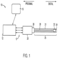
- the system 10 includes an analysis and instrumentation unit (AIU) 12, which includes a processor and an interferometer for use with the OCT optics of the probe, and an ultrasound generator for use with the IVUS transducer of the probe.
- AIU analysis and instrumentation unit
- the analysis and instrumentation unit 12 is in communication with a display 15.
- the analysis and instrumentation unit 12 is connected by electrical conductors and optical fibers 17 to a patient interface unit (PIU) 20.
- the PIU 20 includes the motors, optical and electrical connections necessary to rotate, translate, and provide current and light to the probe 25.
- the probe 25 is removably coupled to the PIU 20 by way of a removable electrical/optical coupler 26.
- the probe itself includes an optical fiber/electrical conductor combination 28 within a sheath 31.
- the optical fiber/electrical conductor combination 28 connects to the OCT optics 33 and the IVUS transducer 34.
- a view of the OCT/IVUS head 50 of the probe 25 includes an ultrasonic transducer 34 and an optical beam director 52 that is part of the optical train (lenses, collimator, etc) 60 of the OCT optics.
- the electrical conductors 64 and optical fiber 68 form the optical fiber/electrical conductor combination 28.
- the ultrasonic transducer 34 generates an ultrasonic beam 80 perpendicular to the surface of the transducer 34.
- the beam director 52 directs light along a beam 84 substantially parallel to the ultrasonic beam 80.
- the two beams, ultrasonic and light should be directed in parallel but due to manufacturing limitations the may deviate by a few degrees ( ⁇ ). The result is that the IVUS image of the vessel and the OCT image of the vessel may be rotated ( ⁇ ) degrees with respect to one another ( Fig. 2B ).
- the path 90 of the optical beam 84 and ultrasound beam 80 against the vessel wall is in the form of a spiral.
- the IVUS transducer 34 is further forward in the probe head than the beam director 54, so that as the probe head 50 is withdrawn from the vessel (directional arrow P), the OCT beam 84 images an area of the vessel (S OCT ) several revolutions of the head 50 earlier than the ultrasound beam 80 images substantially the same the area (S US ).
- the software of the system must take into account the delay caused by the difference in placement of the IVUS transducer 34 and the beam director 54 in the head of the probe 50.
- the IVUS image and the OCT image may be rotated with respect to one another as described above.
- the system can self-calibrate using one of several imaging techniques.
- the sheath 31 ( Fig. 1 ) is manufactured with a discontinuous cylindrical annulus 100 attached to the outside wall or inside wall of the sheath 31.
- Fig. 4(b) an end-on view of the annulus 100' is shown.
- the sheath may have a fiducial bar 104, shown end-on in Fig. 4(c) .
- the fiducial bar 104 and discontinuous cylindrical annulus 100 collectively referred to as a fiducial marker, provide an asymmetry in the image which is detectable by both OCT and IVUS imaging.
- fiducial bar 104 and the discontinuous fiducial annulus 100 are not used together on the same sheath 31, and are shown together only to provide positioning information.
- the fiducial marker may be made of any optically opaque material that has a different optical density and acoustic attenuation than the sheath 31.
- the fiducial marker may be positioned anywhere along the sheath 31, but generally near one end of the region through which the probe head must pass during pull back.
- Fig. 4(d) shows an image 108 of the marker 100 as seen by one modality, and the same image as seen by the other modality 112.
- the system 10 can then determine how much to rotate the images 112, 116 so as to have the IVUS and OCT images coincide.
- the same software that determines if this form of shadow is a guidewire or a vessel branch in general OCT imaging applications is used to determine the orientation of the image by finding the center point of the shadow.
- a discontinuity in the image of the vessel wall caused by the guidewire also appears in an IVUS image because the guidewire is opaque to the ultrasonic beam.
- the same procedure can be used with asymmetries in the vessel wall itself.
- an image of a vessel cross-section may show that the vessel is not circular but is some other shape, such as ellipsoidal, that is not a 360° symmetrical shape.
- both OCT and IVUS image generating programs are capable of finding the major and minor axes of the cross-section. Once these axes are found, one image is rotated until the major and minor axes of the images of both modalities are in register.
- This technique can also be done using some other asymmetry in the vessel cross-sectional image, for example the presence of plaque. However, identifying a specific plaque lesion by one or the other modality may be difficult.
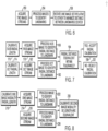
- a generalized flow chart of the method for rotationally aligning two images is shown.
- the two images to be aligned are acquired 150, and landmarks, as discussed above, are identified 154.
- the magnification for the two images is equalized.
- the images are then rotated until the distance between the same point of the landmark in both images is minimized 158.
- the measurement arm of the interferometer includes the length of the fiber in the probe itself, and the length of the fiber connecting the probe to the interferometer. This means that small distance measurements within a vessel are a very small part in what is a very long measurement arm.
- the fiber in the probe is substantially at the temperature of the fluid used to flush blood from the vessel, while portions of the rest of the fiber measurement arm that are not in contact with the flush fluid may be at a different temperatures. Because these temperatures may vary over time, the lengths of the various fiber portions exposed to different changing temperatures will change differentially from one another, causing the interference fringes to shift. The resulting error in the measurement of distance in the lumen is therefore large.
- One attempt to address this error is to put a known reflector in the light path at an approximately known distance from the probe head.
- This reflector is generally placed on the sheath that surrounds the optical fiber. This reflector provides an approximate distance value that may then be used to calibrate distances in the OCT image.
- a second method of checking the calibration of the OCT system is desired. The IVUS portion of the probe is used for this purpose.
- the time it takes for an ultrasonic pulse to move from the transducer and return to the transducer after reflecting from the wall of the vessel can be measured very accurately, and because the speed of sound in the flush solution is known, the distance to the surface of the wall is accurately known. Therefore, by comparing the distance to the wall as measured by OCT and the distance to the wall as measured by IVUS, the accuracy of the calibration of the OCT portion of the device may be determined.
- an IVUS image 178 and an OCT image 182 of the vessel are acquired.
- Each image is processed (186 for IVUS and 190 for OCT) to measure the distance from the center probe location in the lumen to the wall in the vessel.
- the two distance measurements (OCT and IVUS) are compared 194 to determine if they are equivalent to within a predetermined value. If they are, the calibration is deemed accurate 198 and their relative magnifications are known. If they are not, the systems must be recalibrated 202.
- FIG. 8 another embodiment of a method to calibrate an IVUS and an OCT system is to calibrate 210 one of the modalities IVUS or OCT (typically the IVUS portion) and then acquire an image of the vessel with that modality 214.
- An image is acquired with the other modality 218 and each image is processed 222, 226 to measure the distance from the center of the probe location in the lumen to a landmark, such as a wall.
- the two distance measurements are compared 230 to determine if they are equivalent to within a predetermined value and if they are not, the uncalibrated modality is adjusted until the lengths are equivalent.
- the combined modalities are useful in confirming the identity of the fluid being used as a flushing fluid.
- the distance to a landmark on the wall of the vessel is measured using OCT.
- the time it takes for the IVUS ultrasonic pulse to reach the same landmark and return is also measured.
- the speed of sound in the fluid is calculated.
- looking up the speed of sound in the various possible flushing solutions one can determine which solution is being used. If the solution as determined by the method is different from the solution name entered into the system by the clinician during the setup of the imaging procedure, an alarm may be given that the wrong fluid is being used and hence the measurements may not be correct.
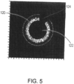
- a probe head 50 is shown within a sheath 31 within the lumen 122 of a vessel 250.
- a lesion 254 on the wall 250 is subjected to the OCT light beam 258 and the IVUS acoustic beam 262.
- the OCT beam 258 measures the distance to the surface 264 of the lesion 254 and the distance to another landmark 268 inside the lesion 254. From these two measurements, the thickness of the lesion 254 between its surface 264 and the landmark 268 is determined. The time it takes for the IVUS acoustic pulse to reach the same surface 264 of the lesion and the time it takes for the acoustic pulse to reach the landmark 268 is also measured.
- the transit time through the lesion is calculated.
- the speed of sound in the lesion is determined. Because different lesions are characterized by different speeds of sound, the type of lesion can then be determined.
- the OCT and IVUS image data can be combined by displaying OCT data for a specific depth of the image and then limiting the rest of the data displayed after that depth to IVUS data.
- This approach can be modified such that the OCT data is displayed until the depth where the OCT signal can no longer be discerned above the noise floor is reached, and then the remainder of the image is filled in with the deeper penetrating IVUS image data.
- each sample is a weighted combination of the IVUS and OCT grayscale adjusted for sample depth, and grayscale of adjacent samples.
- each of the IVUS data set and the OCT data set includes a respective grayscale for each sample and depth information for each sample.
- the method includes the step of generating a combined grayscale for each sample in an image generated using the OCT data set and the IVUS data.
- the combined grayscale is based on the grayscale of the IVUS dataset and the grayscale of the OCT dataset in the sample and the surrounding samples, as well as the depth of that sample.
- identification of the tissue type may be possible by contrasting the differential absorption of the IVUS and OCT energy by a sample. That is, tissue that is reflective in one domain (OCT) may be transmissive in the other domain (IVUS). Thus, it is possible to highlight a region as a calcium plaque or lipid plaque based on differences in transmission.
- compositions are described as having, including, or comprising specific components, or where processes are described as having, including or comprising specific process steps, it is contemplated that compositions of the present teachings also consist essentially of, or consist of, the recited components, and that the processes of the present teachings also consist essentially of, or consist of, the recited process steps.
- each intervening value between the upper and lower limits of that range or list of values is individually contemplated and is encompassed within the invention as if each value were specifically enumerated herein.
- smaller ranges between and including the upper and lower limits of a given range are contemplated and encompassed within the invention.
- the listing of exemplary values or ranges is not a disclaimer of other values or ranges between and including the upper and lower limits of a given range.
Landscapes
- Health & Medical Sciences (AREA)
- Life Sciences & Earth Sciences (AREA)
- Engineering & Computer Science (AREA)
- Heart & Thoracic Surgery (AREA)
- Public Health (AREA)
- Biophysics (AREA)
- Veterinary Medicine (AREA)
- Pathology (AREA)
- Physics & Mathematics (AREA)
- Biomedical Technology (AREA)
- General Health & Medical Sciences (AREA)
- Medical Informatics (AREA)
- Molecular Biology (AREA)
- Surgery (AREA)
- Animal Behavior & Ethology (AREA)
- Radiology & Medical Imaging (AREA)
- Nuclear Medicine, Radiotherapy & Molecular Imaging (AREA)
- Computer Vision & Pattern Recognition (AREA)
- Ultra Sonic Daignosis Equipment (AREA)
- Endoscopes (AREA)
Claims (12)
- Computerimplementiertes Verfahren, um ein IVUS-Bild eines Bereichs eines Lumens und ein OCT-Bild desselben Bereichs des Lumens in Übereinstimmung zu bringen, das Verfahren umfassend:Empfangen, durch einen oder mehr Prozessoren, des IVUS-Bildes des Bereichs des Lumens;Empfangen, durch den einen oder mehr Prozessoren, des OCT-Bildes desselben Bereichs des Lumens;Bestimmen derselben Asymmetrie in jedem der IVUS- und OCT-Bilder; undÜberlagern der IVUS- und OCT-Bilder und Drehen dieser in Bezug zueinander, bis die Asymmetrien in jedem der IVUS- und OCT-Bilder übereinstimmen.
- Verfahren nach Anspruch 1, das weiter das Bestimmen eines Drehwinkels umfasst, der bei der Registrierung verursacht wurde.
- Verfahren nach Anspruch 1 oder 2, wobei die Asymmetrie durch eine Passermarke (100, 104) bereitgestellt wird.
- Verfahren nach Anspruch 3, wobei die Passermarke (100, 104) entlang einer Hülle (31) positioniert wurde, in der ein IVUS/OCT Sondenkopf (50) zum Erhalt der IVUS- und OCT-Bilder positioniert wurde.
- Verfahren nach Anspruch 4, wobei das IVUS-Bild eines Bereichs eines Lumens und das OCT-Bild desselben Bereichs des Lumens erhalten wurden, indem der IVUS/OCT-Sondenkopf (50) in der Hülle (31) gedreht wird.
- Verfahren nach Anspruch 3, 4 oder 5, wobei die Passermarke mindestens eines der folgenden umfasst: einen Passermarkenstrich (104); und einen nicht durchgängigen zylinderförmigen Ringraum (100).
- Verfahren nach Anspruch 6, wobei die Passermarke einen nicht durchgängigen zylindrischen Ringraum (100) umfasst, und wobei das Bestimmen des Drehwinkels weiter das Bestimmen einer Ausrichtungsabweichung zwischen einer ersten Aufteilung in dem nicht durchgängigen zylindrischen Ringraum (116) in dem IVUS-Bild und einer zweiten Aufteilung in dem nicht durchgängigen zylindrischen Ringraum (112) des OCT-Bildes umfasst.
- Verfahren nach einem der Ansprüche 3 bis 7, wobei die Passermarke eine optische Dichte und eine Schallschwächung aufweist, die sich von denen der Hülle (31) unterscheiden.
- Verfahren nach einem der Ansprüche 3 bis 8, das weiter das Bestimmen einer Ausrichtung der Passermarke (100, 104) in jedem der IVUS- und OCT-Bilder umfasst.
- Verfahren nach einem der vorhergehenden Ansprüche, wobei die Asymmetrie in dem OCT-Bild und dem IVUS-Bild weiter verursacht wird durch:einen Führungsdraht; und/odereine Form des Lumens, das abgebildet wird; und/odereine internistische Morphologie des Lumens.
- Prozessor, der zur Ausführung des Verfahrens nach einem der vorhergehenden Ansprüche angeordnet ist.
- Sonde (10) zur OCT- und IVUS-Bildgebung, umfassend: eine Hülle (31) mit einem ersten Ende und einem zweiten Ende und mit einer Wand, die ein Lumen bestimmt; eine Marke (100, 104), die undurchlässig für Licht und Ultraschall ist und zwischen dem ersten Ende und dem zweiten Ende der Hülle angeordnet ist; einen IVUS/OCT-Sondenkopf (50), der innerhalb der Hülle positioniert ist; und den Prozessor nach Anspruch 11.
Priority Applications (1)
| Application Number | Priority Date | Filing Date | Title |
|---|---|---|---|
| EP25183341.4A EP4613210A3 (de) | 2013-03-15 | 2014-02-21 | Vorrichtung und verfahren zur bildregistrierung |
Applications Claiming Priority (2)
| Application Number | Priority Date | Filing Date | Title |
|---|---|---|---|
| US13/836,354 US9833221B2 (en) | 2013-03-15 | 2013-03-15 | Apparatus and method of image registration |
| EP14156269.4A EP2777486A3 (de) | 2013-03-15 | 2014-02-21 | Vorrichtung und Verfahren zur Bildregistrierung |
Related Parent Applications (1)
| Application Number | Title | Priority Date | Filing Date |
|---|---|---|---|
| EP14156269.4A Division EP2777486A3 (de) | 2013-03-15 | 2014-02-21 | Vorrichtung und Verfahren zur Bildregistrierung |
Related Child Applications (1)
| Application Number | Title | Priority Date | Filing Date |
|---|---|---|---|
| EP25183341.4A Division EP4613210A3 (de) | 2013-03-15 | 2014-02-21 | Vorrichtung und verfahren zur bildregistrierung |
Publications (3)
| Publication Number | Publication Date |
|---|---|
| EP4052639A2 EP4052639A2 (de) | 2022-09-07 |
| EP4052639A3 EP4052639A3 (de) | 2022-12-14 |
| EP4052639B1 true EP4052639B1 (de) | 2025-06-25 |
Family
ID=50238109
Family Applications (3)
| Application Number | Title | Priority Date | Filing Date |
|---|---|---|---|
| EP14156269.4A Ceased EP2777486A3 (de) | 2013-03-15 | 2014-02-21 | Vorrichtung und Verfahren zur Bildregistrierung |
| EP25183341.4A Pending EP4613210A3 (de) | 2013-03-15 | 2014-02-21 | Vorrichtung und verfahren zur bildregistrierung |
| EP22170502.3A Active EP4052639B1 (de) | 2013-03-15 | 2014-02-21 | Vorrichtung und verfahren zur bildregistrierung |
Family Applications Before (2)
| Application Number | Title | Priority Date | Filing Date |
|---|---|---|---|
| EP14156269.4A Ceased EP2777486A3 (de) | 2013-03-15 | 2014-02-21 | Vorrichtung und Verfahren zur Bildregistrierung |
| EP25183341.4A Pending EP4613210A3 (de) | 2013-03-15 | 2014-02-21 | Vorrichtung und verfahren zur bildregistrierung |
Country Status (4)
| Country | Link |
|---|---|
| US (2) | US9833221B2 (de) |
| EP (3) | EP2777486A3 (de) |
| JP (1) | JP2014180575A (de) |
| ES (1) | ES3039129T3 (de) |
Families Citing this family (48)
| Publication number | Priority date | Publication date | Assignee | Title |
|---|---|---|---|---|
| WO2013145635A1 (ja) * | 2012-03-26 | 2013-10-03 | テルモ株式会社 | プローブ及び画像診断装置 |
| JP6352287B2 (ja) | 2012-11-19 | 2018-07-04 | ライトラボ・イメージング・インコーポレーテッド | マルチモーダル・イメージングシステム、プローブ及び方法 |
| KR102273831B1 (ko) * | 2014-01-07 | 2021-07-07 | 삼성메디슨 주식회사 | 의료 영상을 디스플레이 하는 방법 및 그 의료 영상 장치 |
| WO2016152624A1 (ja) * | 2015-03-24 | 2016-09-29 | テルモ株式会社 | 画像診断装置及びその制御方法、プログラム及びコンピュータ可読記憶媒体 |
| WO2016168605A1 (en) | 2015-04-16 | 2016-10-20 | Gentuity, Llc | Micro-optic probes for neurology |
| US10646198B2 (en) | 2015-05-17 | 2020-05-12 | Lightlab Imaging, Inc. | Intravascular imaging and guide catheter detection methods and systems |
| US10109058B2 (en) | 2015-05-17 | 2018-10-23 | Lightlab Imaging, Inc. | Intravascular imaging system interfaces and stent detection methods |
| US9996921B2 (en) | 2015-05-17 | 2018-06-12 | LIGHTLAB IMAGING, lNC. | Detection of metal stent struts |
| US10140712B2 (en) | 2015-05-17 | 2018-11-27 | Lightlab Imaging, Inc. | Detection of stent struts relative to side branches |
| US10222956B2 (en) | 2015-05-17 | 2019-03-05 | Lightlab Imaging, Inc. | Intravascular imaging user interface systems and methods |
| AU2016297930B2 (en) | 2015-07-25 | 2021-02-18 | Lightlab Imaging, Inc. | Intravascular data visualization method |
| EP4675259A3 (de) | 2015-08-31 | 2026-04-08 | Spryte Medical, Inc. | Bildgebungssystem mit bildgebungssonde und abgabevorrichtungen |
| CA3005242A1 (en) | 2015-11-18 | 2017-05-26 | Lightlab Imaging, Inc. | Detection of stent struts relative to side branches |
| JP6898927B2 (ja) | 2015-11-23 | 2021-07-07 | ライトラボ・イメージング・インコーポレーテッド | 血管内画像における影の検出および検証 |
| DE102016103796A1 (de) * | 2016-03-03 | 2017-09-07 | Otto-Von-Guericke-Universität Magdeburg | Marker für medizinische Instrumente |
| JP6750000B2 (ja) | 2016-03-25 | 2020-09-02 | テルモ株式会社 | 画像診断装置、画像診断装置の制御方法、コンピュータプログラム、コンピュータ読み取り可能な記憶媒体 |
| EP3435879B8 (de) * | 2016-03-30 | 2020-04-08 | Koninklijke Philips N.V. | Gewebe- und gefässbahnkartierung mit synchronisierten fotoakustischen und ultraschallrückzugstechniken |
| US10593037B2 (en) | 2016-04-14 | 2020-03-17 | Lightlab Imaging, Inc. | Method, apparatus, and system to identify branches of a blood vessel |
| WO2017201026A1 (en) | 2016-05-16 | 2017-11-23 | Lightlab Imaging, Inc. | Intravascular absorbable stent detection and diagnostic methods and systems |
| CN117398183A (zh) | 2016-09-28 | 2024-01-16 | 光学实验室成像公司 | 利用血管表象的支架规划系统及方法 |
| EP3595517B1 (de) | 2017-03-13 | 2024-11-20 | Intuitive Surgical Operations, Inc. | Systeme und verfahren für medizinische verfahren unter verwendung optischer kohärenztomographieerfassung |
| US10842589B2 (en) | 2017-03-21 | 2020-11-24 | Canon U.S.A., Inc. | Method for displaying an anatomical image of a coronary artery on a graphical user interface |
| JP7054411B2 (ja) | 2017-07-26 | 2022-04-13 | キヤノン ユーエスエイ,インコーポレイテッド | 血管造影画像を用いて心臓運動を評価するための方法 |
| WO2019070702A1 (en) | 2017-10-02 | 2019-04-11 | Lightlab Imaging, Inc. | INTRAVASCULAR DATA COLLECTION PROBES AND ASSOCIATED ASSEMBLIES |
| US10621748B2 (en) | 2017-10-03 | 2020-04-14 | Canon U.S.A., Inc. | Detecting and displaying stent expansion |
| US11571129B2 (en) | 2017-10-03 | 2023-02-07 | Canon U.S.A., Inc. | Detecting and displaying stent expansion |
| JP7160935B2 (ja) | 2017-11-28 | 2022-10-25 | ジェンテュイティ・リミテッド・ライアビリティ・カンパニー | 撮像システム |
| CN108464817A (zh) * | 2018-03-28 | 2018-08-31 | 深圳英美达医疗技术有限公司 | 一种双模成像系统及其成像方法 |
| US11344373B2 (en) | 2018-05-29 | 2022-05-31 | Lightlab Imaging, Inc. | Stent expansion display, systems, and methods |
| JP2022500174A (ja) | 2018-09-17 | 2022-01-04 | ジェンテュイティ・リミテッド・ライアビリティ・カンパニーGentuity, LLC | 光学経路を有する撮像システム |
| EP4272654B1 (de) | 2018-10-26 | 2025-12-10 | Koninklijke Philips N.V. | Geschwindigkeitsbestimmung für intraluminale ultraschallbildgebung und zugehörige vorrichtungen, systeme und verfahren |
| CN109584195B (zh) * | 2018-11-20 | 2023-03-28 | 深圳英美达医疗技术有限公司 | 一种双模图像自动融合方法 |
| US12076177B2 (en) | 2019-01-30 | 2024-09-03 | Canon U.S.A., Inc. | Apparatuses, systems, methods and storage mediums for performance of co-registration |
| WO2020223433A1 (en) | 2019-04-30 | 2020-11-05 | Gentuity, Llc | Imaging probe with fluid pressurization element |
| US12239412B2 (en) | 2019-05-21 | 2025-03-04 | Spryte Medical, Inc. | Systems and methods for OCT-guided treatment of a patient |
| US12109056B2 (en) | 2019-09-17 | 2024-10-08 | Canon U.S.A., Inc. | Constructing or reconstructing 3D structure(s) |
| US12239420B2 (en) * | 2019-10-16 | 2025-03-04 | Canon U.S.A., Inc. | Image processing to determine longitudinal orientation and generate tomographic and longitudinal views |
| CN111012369B (zh) * | 2019-12-19 | 2023-07-04 | 武汉阿格斯科技有限公司 | 成像导管同步信号控制方法、系统以及控制器和介质 |
| WO2021199962A1 (ja) * | 2020-03-30 | 2021-10-07 | テルモ株式会社 | プログラム、情報処理方法および情報処理装置 |
| US11571260B2 (en) | 2020-03-31 | 2023-02-07 | Biosense Webster (Israel) Ltd. | Pre-operative registration of anatomical images with a position-tracking system using ultrasound measurement of skin tissue |
| CN111870344B (zh) * | 2020-05-29 | 2021-06-08 | 中山大学肿瘤防治中心(中山大学附属肿瘤医院、中山大学肿瘤研究所) | 术前导航方法、系统及终端设备 |
| EP4304484B1 (de) | 2021-03-10 | 2025-02-26 | Intuitive Surgical Operations, Inc. | Systeme und verfahren zur registrierung von intraoperativen bilddaten |
| JP7548852B2 (ja) * | 2021-03-22 | 2024-09-10 | テルモ株式会社 | コンピュータプログラム、画像処理方法及び画像処理装置 |
| JP7623175B2 (ja) * | 2021-03-22 | 2025-01-28 | テルモ株式会社 | コンピュータプログラム、画像処理装置の作動方法及び画像処理装置 |
| CN113349737B (zh) * | 2021-06-30 | 2023-05-26 | 深圳英美达医疗技术有限公司 | 一种血管内双模成像系统oct图像的校准方法 |
| WO2023132332A1 (ja) * | 2022-01-06 | 2023-07-13 | テルモ株式会社 | コンピュータプログラム、画像処理方法及び画像処理装置 |
| CN117770877B (zh) * | 2022-09-20 | 2026-05-08 | 慧威医疗科技(台州)有限公司 | 一种超声环扫图像配准方法及其系统 |
| EP4390497A1 (de) * | 2022-12-20 | 2024-06-26 | HyprView | Verfahren zum kombinieren von bildern einer probe aus verschiedenen digitalen bildgebungsvorrichtungen und zugehöriges system |
Family Cites Families (113)
| Publication number | Priority date | Publication date | Assignee | Title |
|---|---|---|---|---|
| US5000185A (en) | 1986-02-28 | 1991-03-19 | Cardiovascular Imaging Systems, Inc. | Method for intravascular two-dimensional ultrasonography and recanalization |
| US5582178A (en) | 1986-02-28 | 1996-12-10 | Cardiovascular Imaging Systems, Inc. | Method and apparatus for intravascular ultrasonography |
| US5076279A (en) | 1990-07-17 | 1991-12-31 | Acuson Corporation | Needle guide for assembly upon an ultrasound imaging transducer |
| US6485413B1 (en) | 1991-04-29 | 2002-11-26 | The General Hospital Corporation | Methods and apparatus for forward-directed optical scanning instruments |
| US5748598A (en) | 1995-12-22 | 1998-05-05 | Massachusetts Institute Of Technology | Apparatus and methods for reading multilayer storage media using short coherence length sources |
| US5465147A (en) | 1991-04-29 | 1995-11-07 | Massachusetts Institute Of Technology | Method and apparatus for acquiring images using a ccd detector array and no transverse scanner |
| DE69227902T3 (de) | 1991-04-29 | 2010-04-22 | Massachusetts Institute Of Technology, Cambridge | Vorrichtung für optische abbildung und messung |
| US5956355A (en) | 1991-04-29 | 1999-09-21 | Massachusetts Institute Of Technology | Method and apparatus for performing optical measurements using a rapidly frequency-tuned laser |
| US6134003A (en) | 1991-04-29 | 2000-10-17 | Massachusetts Institute Of Technology | Method and apparatus for performing optical measurements using a fiber optic imaging guidewire, catheter or endoscope |
| US6111645A (en) | 1991-04-29 | 2000-08-29 | Massachusetts Institute Of Technology | Grating based phase control optical delay line |
| US6564087B1 (en) | 1991-04-29 | 2003-05-13 | Massachusetts Institute Of Technology | Fiber optic needle probes for optical coherence tomography imaging |
| US6501551B1 (en) | 1991-04-29 | 2002-12-31 | Massachusetts Institute Of Technology | Fiber optic imaging endoscope interferometer with at least one faraday rotator |
| DE4128744C1 (de) | 1991-08-29 | 1993-04-22 | Siemens Ag, 8000 Muenchen, De | |
| US5274551A (en) | 1991-11-29 | 1993-12-28 | General Electric Company | Method and apparatus for real-time navigation assist in interventional radiological procedures |
| JP3631257B2 (ja) | 1992-08-28 | 2005-03-23 | オリンパス株式会社 | 電子内視鏡装置 |
| US5350377A (en) | 1992-10-26 | 1994-09-27 | Ultrasonic Sensing & Monitoring Systems, Inc. | Medical catheter using optical fibers that transmit both laser energy and ultrasonic imaging signals |
| US5509093A (en) | 1993-10-13 | 1996-04-16 | Micron Optics, Inc. | Temperature compensated fiber fabry-perot filters |
| JP2848586B2 (ja) | 1994-10-03 | 1999-01-20 | オリンパス光学工業株式会社 | 超音波診断装置 |
| US5619368A (en) | 1995-05-16 | 1997-04-08 | Massachusetts Inst. Of Technology | Optical frequency shifter |
| WO1997001167A1 (en) | 1995-06-21 | 1997-01-09 | Massachusetts Institute Of Technology | Apparatus and method for accessing data on multilayered optical media |
| US6302875B1 (en) * | 1996-10-11 | 2001-10-16 | Transvascular, Inc. | Catheters and related devices for forming passageways between blood vessels or other anatomical structures |
| US5830145A (en) | 1996-09-20 | 1998-11-03 | Cardiovascular Imaging Systems, Inc. | Enhanced accuracy of three-dimensional intraluminal ultrasound (ILUS) image reconstruction |
| US6314197B1 (en) * | 1997-08-22 | 2001-11-06 | International Business Machines Corporation | Determining an alignment estimation between two (fingerprint) images |
| JP3772002B2 (ja) | 1997-08-28 | 2006-05-10 | オリンパス株式会社 | 被検体内断層イメージング装置 |
| GB2329708B (en) | 1997-09-24 | 2002-05-08 | Roke Manor Research | Catheter localisation system |
| US6217527B1 (en) | 1998-09-30 | 2001-04-17 | Lumend, Inc. | Methods and apparatus for crossing vascular occlusions |
| US6129667A (en) | 1998-02-02 | 2000-10-10 | General Electric Company | Luminal diagnostics employing spectral analysis |
| US20020161351A1 (en) | 1998-09-01 | 2002-10-31 | Samson Wilfred J. | Method and apparatus for treating acute myocardial infarction with selective hypothermic perfusion |
| US6191862B1 (en) | 1999-01-20 | 2001-02-20 | Lightlab Imaging, Llc | Methods and apparatus for high speed longitudinal scanning in imaging systems |
| US6911026B1 (en) | 1999-07-12 | 2005-06-28 | Stereotaxis, Inc. | Magnetically guided atherectomy |
| US7386339B2 (en) | 1999-05-18 | 2008-06-10 | Mediguide Ltd. | Medical imaging and navigation system |
| US7343195B2 (en) | 1999-05-18 | 2008-03-11 | Mediguide Ltd. | Method and apparatus for real time quantitative three-dimensional image reconstruction of a moving organ and intra-body navigation |
| US6423002B1 (en) | 1999-06-24 | 2002-07-23 | Acuson Corporation | Intra-operative diagnostic ultrasound multiple-array transducer probe and optional surgical tool |
| US6445939B1 (en) | 1999-08-09 | 2002-09-03 | Lightlab Imaging, Llc | Ultra-small optical probes, imaging optics, and methods for using same |
| US6299622B1 (en) | 1999-08-19 | 2001-10-09 | Fox Hollow Technologies, Inc. | Atherectomy catheter with aligned imager |
| US6265792B1 (en) | 1999-09-08 | 2001-07-24 | Endosonics Corporation | Medical device having precision interconnect |
| US8644907B2 (en) | 1999-10-28 | 2014-02-04 | Medtronic Navigaton, Inc. | Method and apparatus for surgical navigation |
| US8239001B2 (en) | 2003-10-17 | 2012-08-07 | Medtronic Navigation, Inc. | Method and apparatus for surgical navigation |
| US7366562B2 (en) | 2003-10-17 | 2008-04-29 | Medtronic Navigation, Inc. | Method and apparatus for surgical navigation |
| EP1434522B1 (de) | 2000-10-30 | 2010-01-13 | The General Hospital Corporation | Optische systeme zur gewebeanalyse |
| JP2002153472A (ja) | 2000-11-22 | 2002-05-28 | Fuji Photo Film Co Ltd | 画像診断装置 |
| US6768756B2 (en) | 2001-03-12 | 2004-07-27 | Axsun Technologies, Inc. | MEMS membrane with integral mirror/lens |
| US6570659B2 (en) | 2001-03-16 | 2003-05-27 | Lightlab Imaging, Llc | Broadband light source system and method and light source combiner |
| US6552796B2 (en) | 2001-04-06 | 2003-04-22 | Lightlab Imaging, Llc | Apparatus and method for selective data collection and signal to noise ratio enhancement using optical coherence tomography |
| US6585660B2 (en) | 2001-05-18 | 2003-07-01 | Jomed Inc. | Signal conditioning device for interfacing intravascular sensors having varying operational characteristics to a physiology monitor |
| US6706004B2 (en) | 2001-05-31 | 2004-03-16 | Infraredx, Inc. | Balloon catheter |
| US6879851B2 (en) | 2001-06-07 | 2005-04-12 | Lightlab Imaging, Llc | Fiber optic endoscopic gastrointestinal probe |
| US6847454B2 (en) | 2001-07-16 | 2005-01-25 | Scimed Life Systems, Inc. | Systems and methods for processing signals from an interferometer by an ultrasound console |
| US6947787B2 (en) | 2001-12-21 | 2005-09-20 | Advanced Cardiovascular Systems, Inc. | System and methods for imaging within a body lumen |
| DE10203651B4 (de) | 2002-01-30 | 2004-04-01 | Aloys Wobben | Übertrager |
| US7134994B2 (en) | 2002-05-20 | 2006-11-14 | Volcano Corporation | Multipurpose host system for invasive cardiovascular diagnostic measurement acquisition and display |
| US7477763B2 (en) | 2002-06-18 | 2009-01-13 | Boston Scientific Scimed, Inc. | Computer generated representation of the imaging pattern of an imaging device |
| WO2004000112A2 (en) | 2002-06-25 | 2003-12-31 | Glucon Inc. | Method and apparatus for determining tissue viability |
| US6891984B2 (en) | 2002-07-25 | 2005-05-10 | Lightlab Imaging, Llc | Scanning miniature optical probes with optical distortion correction and rotational control |
| US7359554B2 (en) | 2002-08-26 | 2008-04-15 | Cleveland Clinic Foundation | System and method for identifying a vascular border |
| JP2004290548A (ja) | 2003-03-28 | 2004-10-21 | Toshiba Corp | 画像診断装置、診断・治療装置及び診断・治療方法 |
| US20050149002A1 (en) | 2003-04-08 | 2005-07-07 | Xingwu Wang | Markers for visualizing interventional medical devices |
| US20050025797A1 (en) | 2003-04-08 | 2005-02-03 | Xingwu Wang | Medical device with low magnetic susceptibility |
| US7241286B2 (en) | 2003-04-25 | 2007-07-10 | Lightlab Imaging, Llc | Flush catheter with flow directing sheath |
| US20100076320A1 (en) | 2003-04-25 | 2010-03-25 | Lightlab Imaging, Llc | Flush catheter with flow directing sheath |
| CA2535942A1 (en) * | 2003-08-21 | 2005-03-10 | Ischem Corporation | Automated methods and systems for vascular plaque detection and analysis |
| DE10343808B4 (de) | 2003-09-22 | 2017-06-01 | Siemens Healthcare Gmbh | Medizinisches Untersuchungs- und/oder Behandlungssystem |
| US7840253B2 (en) | 2003-10-17 | 2010-11-23 | Medtronic Navigation, Inc. | Method and apparatus for surgical navigation |
| DE10354496B4 (de) | 2003-11-21 | 2011-03-31 | Siemens Ag | Medizinisches Untersuchungs- und/oder Behandlungssystem |
| US7397935B2 (en) | 2004-05-10 | 2008-07-08 | Mediguide Ltd. | Method for segmentation of IVUS image sequences |
| CN1322839C (zh) | 2004-06-28 | 2007-06-27 | 天津大学 | 医用经内窥镜微型超声-oct探头 |
| WO2006037001A1 (en) | 2004-09-24 | 2006-04-06 | Lightlab Imaging, Inc. | Fluid occluding devices and methods |
| DE102005045071A1 (de) | 2005-09-21 | 2007-04-12 | Siemens Ag | Kathetervorrichtung mit einem Positionssensorsystem zur Behandlung eines teilweisen und/oder vollständigen Gefäßverschlusses unter Bildüberwachung |
| US20060116577A1 (en) | 2004-11-30 | 2006-06-01 | Siemens Medical Solutions Usa, Inc. | Direct image measurement editing mode for ultrasound reports |
| DE102004058008B4 (de) | 2004-12-01 | 2007-08-23 | Siemens Ag | Führungsdraht für Gefäßkatheter mit verbesserter Ortungs- und Navigiermöglichkeit |
| US7621874B2 (en) | 2004-12-14 | 2009-11-24 | Scimed Life Systems, Inc. | Systems and methods for improved three-dimensional imaging of a body lumen |
| WO2006076409A2 (en) * | 2005-01-11 | 2006-07-20 | Volcano Corporation | Vascular image co-registration |
| US8315282B2 (en) | 2005-01-20 | 2012-11-20 | Massachusetts Institute Of Technology | Fourier domain mode locking: method and apparatus for control and improved performance |
| EP1839375B1 (de) | 2005-01-20 | 2014-06-04 | Massachusetts Institute of Technology | Verfahren und Vorrichtung zur Modenkopplung |
| WO2006086700A2 (en) | 2005-02-10 | 2006-08-17 | Lightlab Imaging, Inc. | Optical coherence tomography apparatus and methods |
| US7415049B2 (en) | 2005-03-28 | 2008-08-19 | Axsun Technologies, Inc. | Laser with tilted multi spatial mode resonator tuning element |
| US9468500B2 (en) | 2005-04-26 | 2016-10-18 | Tea Time Partners, L.P. | Image-guided laser catheter |
| US8162834B2 (en) | 2006-10-18 | 2012-04-24 | Board Of Regents, The University Of Texas System | Hemoglobin contrast in ultrasound and optical coherence tomography for diagnosing diseased tissue, cancers, and the like |
| EP1903944B1 (de) | 2005-06-24 | 2017-04-19 | Volcano Corporation | Ko-aufzeichnung grafischer bilddaten mit darstellung dreidimensionaler gefässmerkmale |
| DE102005032755B4 (de) | 2005-07-13 | 2014-09-04 | Siemens Aktiengesellschaft | System zur Durchführung und Überwachung minimal-invasiver Eingriffe |
| EP1921998B8 (de) * | 2005-08-10 | 2021-07-07 | C.R.Bard, Inc. | Biopsievorrichtung mit linearantrieb für mehrfache probennahme mit einzeleinführung |
| US20070135803A1 (en) * | 2005-09-14 | 2007-06-14 | Amir Belson | Methods and apparatus for performing transluminal and other procedures |
| DE102005048892B4 (de) | 2005-09-22 | 2009-01-15 | Siemens Ag | Vorrichtung zur Durchführung von Rotablation sowie medizinische Behandlungseinrichtung |
| JP6046325B2 (ja) | 2005-09-29 | 2016-12-14 | ザ ジェネラル ホスピタル コーポレイション | 漸次的に解像度を増加させて1以上の生物学的サンプルの観察及び分析のための方法及びその方法のための装置 |
| US20070232933A1 (en) | 2005-10-13 | 2007-10-04 | Volcano Corporation | Component-based catheter lab intravascular ultrasound system |
| US20070243137A1 (en) | 2006-04-18 | 2007-10-18 | Nanoprobes, Inc. | Cell and sub-cell methods for imaging and therapy |
| US8029447B2 (en) | 2006-10-10 | 2011-10-04 | Volcano Corporation | Multipurpose host system for invasive cardiovascular diagnostic measurement acquisition including an enhanced dynamically configured graphical display |
| JP2010508973A (ja) | 2006-11-08 | 2010-03-25 | ライトラブ イメージング, インコーポレイテッド | 光−音響イメージングデバイスおよび方法 |
| ES3007239T3 (en) | 2007-01-10 | 2025-03-19 | Lightlab Imaging Inc | Methods and apparatus for swept-source optical coherence tomography |
| CN103222846B (zh) | 2007-01-19 | 2017-04-26 | 桑尼布鲁克健康科学中心 | 用于成像探头的扫描机构 |
| US8460195B2 (en) | 2007-01-19 | 2013-06-11 | Sunnybrook Health Sciences Centre | Scanning mechanisms for imaging probe |
| WO2008091961A2 (en) | 2007-01-23 | 2008-07-31 | Volcano Corporation | Optical coherence tomography implementation |
| US10219780B2 (en) | 2007-07-12 | 2019-03-05 | Volcano Corporation | OCT-IVUS catheter for concurrent luminal imaging |
| WO2009009799A1 (en) | 2007-07-12 | 2009-01-15 | Volcano Corporation | Catheter for in vivo imaging |
| WO2009021179A1 (en) | 2007-08-09 | 2009-02-12 | Volcano Corporation | Controller user interface for a catheter lab intravascular ultrasound system |
| US8582934B2 (en) | 2007-11-12 | 2013-11-12 | Lightlab Imaging, Inc. | Miniature optical elements for fiber-optic beam shaping |
| US7813609B2 (en) | 2007-11-12 | 2010-10-12 | Lightlab Imaging, Inc. | Imaging catheter with integrated reference reflector |
| US20110190586A1 (en) | 2008-03-28 | 2011-08-04 | Volcano Corporation | Methods and systems for intravascular imaging and flushing |
| JP2011519689A (ja) | 2008-05-07 | 2011-07-14 | インフラレデックス, インコーポレイテッド | 脈管内分析のためのマルチモーダルカテーテルシステム |
| ES2517915T3 (es) | 2008-06-02 | 2014-11-04 | Lightlab Imaging, Inc. | Métodos cuantitativos para obtener características de un tejido a partir de imágenes de tomografía por coherencia óptica |
| DE102008045634A1 (de) | 2008-09-03 | 2010-03-04 | Ludwig-Maximilians-Universität München | Wellenlängenabstimmbare Lichtquelle |
| EP3725212A1 (de) | 2008-10-14 | 2020-10-21 | Lightlab Imaging, Inc. | Stentstrebendetektion und zugehörige messung und anzeige mittels optischer kohärenztomographie |
| ES2660570T3 (es) | 2009-09-23 | 2018-03-23 | Lightlab Imaging, Inc. | Sistemas, aparatos y métodos de recopilación de datos de medición de resistencia vascular y morfología luminal |
| WO2011038048A1 (en) | 2009-09-23 | 2011-03-31 | Lightlab Imaging, Inc. | Apparatus, systems, and methods of in-vivo blood clearing in a lumen |
| US8926590B2 (en) | 2009-12-22 | 2015-01-06 | Lightlab Imaging, Inc. | Torque limiter for an OCT catheter |
| US8206377B2 (en) | 2009-12-22 | 2012-06-26 | Lightlab Imaging, Inc. | Torque limiter for an OCT catheter |
| US8478384B2 (en) | 2010-01-19 | 2013-07-02 | Lightlab Imaging, Inc. | Intravascular optical coherence tomography system with pressure monitoring interface and accessories |
| AU2011227178B2 (en) | 2010-03-17 | 2013-11-07 | Lightlab Imaging, Inc. | Intensity noise reduction methods and apparatus for interferometric sensing and imaging systems |
| US8582619B2 (en) | 2011-03-15 | 2013-11-12 | Lightlab Imaging, Inc. | Methods, systems, and devices for timing control in electromagnetic radiation sources |
| US9164240B2 (en) | 2011-03-31 | 2015-10-20 | Lightlab Imaging, Inc. | Optical buffering methods, apparatus, and systems for increasing the repetition rate of tunable light sources |
| CA2836790C (en) | 2011-05-31 | 2019-04-23 | Desmond Adler | Multimodal imaging system, apparatus, and methods |
| US20130051728A1 (en) | 2011-08-31 | 2013-02-28 | Lightlab Imaging, Inc. | Optical Imaging Probes and Related Methods |
| US9237851B2 (en) | 2012-02-03 | 2016-01-19 | Ninepoint Medical, Inc. | Imaging system producing multiple registered images of a body lumen |
-
2013
- 2013-03-15 US US13/836,354 patent/US9833221B2/en active Active
-
2014
- 2014-02-21 ES ES22170502T patent/ES3039129T3/es active Active
- 2014-02-21 EP EP14156269.4A patent/EP2777486A3/de not_active Ceased
- 2014-02-21 EP EP25183341.4A patent/EP4613210A3/de active Pending
- 2014-02-21 EP EP22170502.3A patent/EP4052639B1/de active Active
- 2014-03-14 JP JP2014051804A patent/JP2014180575A/ja active Pending
-
2017
- 2017-12-04 US US15/830,640 patent/US20180085095A1/en not_active Abandoned
Also Published As
| Publication number | Publication date |
|---|---|
| JP2014180575A (ja) | 2014-09-29 |
| ES3039129T3 (en) | 2025-10-17 |
| EP4613210A3 (de) | 2026-01-07 |
| EP4052639A2 (de) | 2022-09-07 |
| US20140276020A1 (en) | 2014-09-18 |
| US20180085095A1 (en) | 2018-03-29 |
| EP4052639A3 (de) | 2022-12-14 |
| EP2777486A2 (de) | 2014-09-17 |
| US9833221B2 (en) | 2017-12-05 |
| EP4613210A2 (de) | 2025-09-10 |
| EP2777486A3 (de) | 2015-04-08 |
Similar Documents
| Publication | Publication Date | Title |
|---|---|---|
| US9833221B2 (en) | Apparatus and method of image registration | |
| US11435233B2 (en) | Calibration and image processing devices, methods, and systems | |
| JP4933827B2 (ja) | 耳道を再構成する方法およびコンピュータ読み出し可能プログラム記憶装置 | |
| CN108351295B (zh) | 使用光纤形状感测生成解剖目标的三维数据的设备和方法 | |
| US12622672B2 (en) | Fiber-optic realshape sensor for enhanced doppler measurement display | |
| JP7208915B2 (ja) | 管腔構造のインサイチュ3次元再構成のための装置、方法、及びコンピュータのアクセス可能な媒体 | |
| US9607381B2 (en) | Accurate and rapid mapping of points from ultrasound images to tracking systems | |
| US8323183B2 (en) | Forward looking optical coherence tomography endoscope | |
| CN104168823B (zh) | 一种血液流速的测量装置及方法 | |
| US20090171205A1 (en) | Method and system for locating blood vessels | |
| JP6674038B2 (ja) | 心血管診断用統合型カテーテル装置及びそれを用いた画像処理システム | |
| JP2006313158A (ja) | 光コヒーレンス断層撮影による管腔の断層画像表示方法および光コヒーレンス断層撮影装置 | |
| US10555723B2 (en) | Imaging apparatus for diagnosis, control method therefor, program, and computer readable storage medium | |
| US20100110414A1 (en) | System, method and computer-accessible medium for tracking vessel motion during three-dimensional coronary artery microscopy | |
| CN107752985B (zh) | Oct成像方法、oct成像导管及oct系统 | |
| HK40131454A (en) | Apparatus and method of image registration | |
| HK40077971A (en) | Apparatus and method of image registration | |
| CN120918587A (zh) | 多模态成像系统性能检测装置及方法 | |
| Mathews et al. | Ultrasonic Tracking of a Rapid-Exchange Microcatheter with Simultaneous Pressure Sensing for Cardiovascular Interventions |
Legal Events
| Date | Code | Title | Description |
|---|---|---|---|
| PUAI | Public reference made under article 153(3) epc to a published international application that has entered the european phase |
Free format text: ORIGINAL CODE: 0009012 |
|
| STAA | Information on the status of an ep patent application or granted ep patent |
Free format text: STATUS: THE APPLICATION HAS BEEN PUBLISHED |
|
| AC | Divisional application: reference to earlier application |
Ref document number: 2777486 Country of ref document: EP Kind code of ref document: P |
|
| AK | Designated contracting states |
Kind code of ref document: A2 Designated state(s): AL AT BE BG CH CY CZ DE DK EE ES FI FR GB GR HR HU IE IS IT LI LT LU LV MC MK MT NL NO PL PT RO RS SE SI SK SM TR |
|
| PUAL | Search report despatched |
Free format text: ORIGINAL CODE: 0009013 |
|
| AK | Designated contracting states |
Kind code of ref document: A3 Designated state(s): AL AT BE BG CH CY CZ DE DK EE ES FI FR GB GR HR HU IE IS IT LI LT LU LV MC MK MT NL NO PL PT RO RS SE SI SK SM TR |
|
| RIC1 | Information provided on ipc code assigned before grant |
Ipc: A61B 8/12 20060101ALI20221107BHEP Ipc: A61B 5/00 20060101AFI20221107BHEP |
|
| REG | Reference to a national code |
Ref country code: HK Ref legal event code: DE Ref document number: 40077971 Country of ref document: HK |
|
| STAA | Information on the status of an ep patent application or granted ep patent |
Free format text: STATUS: REQUEST FOR EXAMINATION WAS MADE |
|
| 17P | Request for examination filed |
Effective date: 20230613 |
|
| RBV | Designated contracting states (corrected) |
Designated state(s): AL AT BE BG CH CY CZ DE DK EE ES FI FR GB GR HR HU IE IS IT LI LT LU LV MC MK MT NL NO PL PT RO RS SE SI SK SM TR |
|
| P01 | Opt-out of the competence of the unified patent court (upc) registered |
Effective date: 20230616 |
|
| GRAP | Despatch of communication of intention to grant a patent |
Free format text: ORIGINAL CODE: EPIDOSNIGR1 |
|
| STAA | Information on the status of an ep patent application or granted ep patent |
Free format text: STATUS: GRANT OF PATENT IS INTENDED |
|
| INTG | Intention to grant announced |
Effective date: 20250127 |
|
| GRAS | Grant fee paid |
Free format text: ORIGINAL CODE: EPIDOSNIGR3 |
|
| GRAA | (expected) grant |
Free format text: ORIGINAL CODE: 0009210 |
|
| STAA | Information on the status of an ep patent application or granted ep patent |
Free format text: STATUS: THE PATENT HAS BEEN GRANTED |
|
| AC | Divisional application: reference to earlier application |
Ref document number: 2777486 Country of ref document: EP Kind code of ref document: P |
|
| AK | Designated contracting states |
Kind code of ref document: B1 Designated state(s): AL AT BE BG CH CY CZ DE DK EE ES FI FR GB GR HR HU IE IS IT LI LT LU LV MC MK MT NL NO PL PT RO RS SE SI SK SM TR |
|
| REG | Reference to a national code |
Ref country code: GB Ref legal event code: FG4D |
|
| REG | Reference to a national code |
Ref country code: CH Ref legal event code: EP |
|
| REG | Reference to a national code |
Ref country code: CH Ref legal event code: EP |
|
| REG | Reference to a national code |
Ref country code: IE Ref legal event code: FG4D |
|
| REG | Reference to a national code |
Ref country code: DE Ref legal event code: R096 Ref document number: 602014092083 Country of ref document: DE |
|
| REG | Reference to a national code |
Ref country code: NL Ref legal event code: FP |
|
| PG25 | Lapsed in a contracting state [announced via postgrant information from national office to epo] |
Ref country code: FI Free format text: LAPSE BECAUSE OF FAILURE TO SUBMIT A TRANSLATION OF THE DESCRIPTION OR TO PAY THE FEE WITHIN THE PRESCRIBED TIME-LIMIT Effective date: 20250625 |
|
| REG | Reference to a national code |
Ref country code: LT Ref legal event code: MG9D |
|
| PG25 | Lapsed in a contracting state [announced via postgrant information from national office to epo] |
Ref country code: GR Free format text: LAPSE BECAUSE OF FAILURE TO SUBMIT A TRANSLATION OF THE DESCRIPTION OR TO PAY THE FEE WITHIN THE PRESCRIBED TIME-LIMIT Effective date: 20250926 Ref country code: NO Free format text: LAPSE BECAUSE OF FAILURE TO SUBMIT A TRANSLATION OF THE DESCRIPTION OR TO PAY THE FEE WITHIN THE PRESCRIBED TIME-LIMIT Effective date: 20250925 |
|
| PG25 | Lapsed in a contracting state [announced via postgrant information from national office to epo] |
Ref country code: BG Free format text: LAPSE BECAUSE OF FAILURE TO SUBMIT A TRANSLATION OF THE DESCRIPTION OR TO PAY THE FEE WITHIN THE PRESCRIBED TIME-LIMIT Effective date: 20250625 |
|
| PG25 | Lapsed in a contracting state [announced via postgrant information from national office to epo] |
Ref country code: HR Free format text: LAPSE BECAUSE OF FAILURE TO SUBMIT A TRANSLATION OF THE DESCRIPTION OR TO PAY THE FEE WITHIN THE PRESCRIBED TIME-LIMIT Effective date: 20250625 |
|
| REG | Reference to a national code |
Ref country code: ES Ref legal event code: FG2A Ref document number: 3039129 Country of ref document: ES Kind code of ref document: T3 Effective date: 20251017 |
|
| PG25 | Lapsed in a contracting state [announced via postgrant information from national office to epo] |
Ref country code: RS Free format text: LAPSE BECAUSE OF FAILURE TO SUBMIT A TRANSLATION OF THE DESCRIPTION OR TO PAY THE FEE WITHIN THE PRESCRIBED TIME-LIMIT Effective date: 20250925 |
|
| PG25 | Lapsed in a contracting state [announced via postgrant information from national office to epo] |
Ref country code: LV Free format text: LAPSE BECAUSE OF FAILURE TO SUBMIT A TRANSLATION OF THE DESCRIPTION OR TO PAY THE FEE WITHIN THE PRESCRIBED TIME-LIMIT Effective date: 20250625 |
|
| PG25 | Lapsed in a contracting state [announced via postgrant information from national office to epo] |
Ref country code: PT Free format text: LAPSE BECAUSE OF FAILURE TO SUBMIT A TRANSLATION OF THE DESCRIPTION OR TO PAY THE FEE WITHIN THE PRESCRIBED TIME-LIMIT Effective date: 20251027 |
|
| REG | Reference to a national code |
Ref country code: AT Ref legal event code: MK05 Ref document number: 1805591 Country of ref document: AT Kind code of ref document: T Effective date: 20250625 |
|
| PG25 | Lapsed in a contracting state [announced via postgrant information from national office to epo] |
Ref country code: IS Free format text: LAPSE BECAUSE OF FAILURE TO SUBMIT A TRANSLATION OF THE DESCRIPTION OR TO PAY THE FEE WITHIN THE PRESCRIBED TIME-LIMIT Effective date: 20251025 |
|
| PG25 | Lapsed in a contracting state [announced via postgrant information from national office to epo] |
Ref country code: AT Free format text: LAPSE BECAUSE OF FAILURE TO SUBMIT A TRANSLATION OF THE DESCRIPTION OR TO PAY THE FEE WITHIN THE PRESCRIBED TIME-LIMIT Effective date: 20250625 Ref country code: SM Free format text: LAPSE BECAUSE OF FAILURE TO SUBMIT A TRANSLATION OF THE DESCRIPTION OR TO PAY THE FEE WITHIN THE PRESCRIBED TIME-LIMIT Effective date: 20250625 |
|
| PG25 | Lapsed in a contracting state [announced via postgrant information from national office to epo] |
Ref country code: CZ Free format text: LAPSE BECAUSE OF FAILURE TO SUBMIT A TRANSLATION OF THE DESCRIPTION OR TO PAY THE FEE WITHIN THE PRESCRIBED TIME-LIMIT Effective date: 20250625 |
|
| PG25 | Lapsed in a contracting state [announced via postgrant information from national office to epo] |
Ref country code: PL Free format text: LAPSE BECAUSE OF FAILURE TO SUBMIT A TRANSLATION OF THE DESCRIPTION OR TO PAY THE FEE WITHIN THE PRESCRIBED TIME-LIMIT Effective date: 20250625 |
|
| PG25 | Lapsed in a contracting state [announced via postgrant information from national office to epo] |
Ref country code: EE Free format text: LAPSE BECAUSE OF FAILURE TO SUBMIT A TRANSLATION OF THE DESCRIPTION OR TO PAY THE FEE WITHIN THE PRESCRIBED TIME-LIMIT Effective date: 20250625 |
|
| PG25 | Lapsed in a contracting state [announced via postgrant information from national office to epo] |
Ref country code: SK Free format text: LAPSE BECAUSE OF FAILURE TO SUBMIT A TRANSLATION OF THE DESCRIPTION OR TO PAY THE FEE WITHIN THE PRESCRIBED TIME-LIMIT Effective date: 20250625 |
|
| PGFP | Annual fee paid to national office [announced via postgrant information from national office to epo] |
Ref country code: GB Payment date: 20260113 Year of fee payment: 13 |
|
| PGFP | Annual fee paid to national office [announced via postgrant information from national office to epo] |
Ref country code: ES Payment date: 20260304 Year of fee payment: 13 |
|
| PG25 | Lapsed in a contracting state [announced via postgrant information from national office to epo] |
Ref country code: DK Free format text: LAPSE BECAUSE OF FAILURE TO SUBMIT A TRANSLATION OF THE DESCRIPTION OR TO PAY THE FEE WITHIN THE PRESCRIBED TIME-LIMIT Effective date: 20250625 |
|
| PGFP | Annual fee paid to national office [announced via postgrant information from national office to epo] |
Ref country code: DE Payment date: 20260115 Year of fee payment: 13 |
|
| PGFP | Annual fee paid to national office [announced via postgrant information from national office to epo] |
Ref country code: BE Payment date: 20260113 Year of fee payment: 13 Ref country code: IT Payment date: 20260212 Year of fee payment: 13 |
|
| PGFP | Annual fee paid to national office [announced via postgrant information from national office to epo] |
Ref country code: FR Payment date: 20260109 Year of fee payment: 13 |
|
| PLBE | No opposition filed within time limit |
Free format text: ORIGINAL CODE: 0009261 |
|
| STAA | Information on the status of an ep patent application or granted ep patent |
Free format text: STATUS: NO OPPOSITION FILED WITHIN TIME LIMIT |
|
| REG | Reference to a national code |
Ref country code: CH Ref legal event code: L10 Free format text: ST27 STATUS EVENT CODE: U-0-0-L10-L00 (AS PROVIDED BY THE NATIONAL OFFICE) Effective date: 20260507 |