EP4052736A1 - Antriebseinheit für eine milchpumpe und milchpumpe - Google Patents
Antriebseinheit für eine milchpumpe und milchpumpe Download PDFInfo
- Publication number
- EP4052736A1 EP4052736A1 EP22163489.2A EP22163489A EP4052736A1 EP 4052736 A1 EP4052736 A1 EP 4052736A1 EP 22163489 A EP22163489 A EP 22163489A EP 4052736 A1 EP4052736 A1 EP 4052736A1
- Authority
- EP
- European Patent Office
- Prior art keywords
- drive unit
- housing
- unit
- breast pump
- components
- Prior art date
- Legal status (The legal status is an assumption and is not a legal conclusion. Google has not performed a legal analysis and makes no representation as to the accuracy of the status listed.)
- Pending
Links
Images
Classifications
-
- A—HUMAN NECESSITIES
- A61—MEDICAL OR VETERINARY SCIENCE; HYGIENE
- A61M—DEVICES FOR INTRODUCING MEDIA INTO, OR ONTO, THE BODY; DEVICES FOR TRANSDUCING BODY MEDIA OR FOR TAKING MEDIA FROM THE BODY; DEVICES FOR PRODUCING OR ENDING SLEEP OR STUPOR
- A61M1/00—Suction or pumping devices for medical purposes; Devices for carrying-off, for treatment of, or for carrying-over, body-liquids; Drainage systems
- A61M1/06—Milking pumps
-
- A—HUMAN NECESSITIES
- A61—MEDICAL OR VETERINARY SCIENCE; HYGIENE
- A61M—DEVICES FOR INTRODUCING MEDIA INTO, OR ONTO, THE BODY; DEVICES FOR TRANSDUCING BODY MEDIA OR FOR TAKING MEDIA FROM THE BODY; DEVICES FOR PRODUCING OR ENDING SLEEP OR STUPOR
- A61M1/00—Suction or pumping devices for medical purposes; Devices for carrying-off, for treatment of, or for carrying-over, body-liquids; Drainage systems
- A61M1/06—Milking pumps
- A61M1/062—Pump accessories
-
- A—HUMAN NECESSITIES
- A61—MEDICAL OR VETERINARY SCIENCE; HYGIENE
- A61M—DEVICES FOR INTRODUCING MEDIA INTO, OR ONTO, THE BODY; DEVICES FOR TRANSDUCING BODY MEDIA OR FOR TAKING MEDIA FROM THE BODY; DEVICES FOR PRODUCING OR ENDING SLEEP OR STUPOR
- A61M2205/00—General characteristics of the apparatus
- A61M2205/02—General characteristics of the apparatus characterised by a particular materials
- A61M2205/0216—Materials providing elastic properties, e.g. for facilitating deformation and avoid breaking
-
- A—HUMAN NECESSITIES
- A61—MEDICAL OR VETERINARY SCIENCE; HYGIENE
- A61M—DEVICES FOR INTRODUCING MEDIA INTO, OR ONTO, THE BODY; DEVICES FOR TRANSDUCING BODY MEDIA OR FOR TAKING MEDIA FROM THE BODY; DEVICES FOR PRODUCING OR ENDING SLEEP OR STUPOR
- A61M2205/00—General characteristics of the apparatus
- A61M2205/10—General characteristics of the apparatus with powered movement mechanisms
-
- A—HUMAN NECESSITIES
- A61—MEDICAL OR VETERINARY SCIENCE; HYGIENE
- A61M—DEVICES FOR INTRODUCING MEDIA INTO, OR ONTO, THE BODY; DEVICES FOR TRANSDUCING BODY MEDIA OR FOR TAKING MEDIA FROM THE BODY; DEVICES FOR PRODUCING OR ENDING SLEEP OR STUPOR
- A61M2205/00—General characteristics of the apparatus
- A61M2205/42—Reducing noise
-
- A—HUMAN NECESSITIES
- A61—MEDICAL OR VETERINARY SCIENCE; HYGIENE
- A61M—DEVICES FOR INTRODUCING MEDIA INTO, OR ONTO, THE BODY; DEVICES FOR TRANSDUCING BODY MEDIA OR FOR TAKING MEDIA FROM THE BODY; DEVICES FOR PRODUCING OR ENDING SLEEP OR STUPOR
- A61M2205/00—General characteristics of the apparatus
- A61M2205/50—General characteristics of the apparatus with microprocessors or computers
- A61M2205/502—User interfaces, e.g. screens or keyboards
-
- A—HUMAN NECESSITIES
- A61—MEDICAL OR VETERINARY SCIENCE; HYGIENE
- A61M—DEVICES FOR INTRODUCING MEDIA INTO, OR ONTO, THE BODY; DEVICES FOR TRANSDUCING BODY MEDIA OR FOR TAKING MEDIA FROM THE BODY; DEVICES FOR PRODUCING OR ENDING SLEEP OR STUPOR
- A61M2205/00—General characteristics of the apparatus
- A61M2205/82—Internal energy supply devices
- A61M2205/8206—Internal energy supply devices battery-operated
-
- A—HUMAN NECESSITIES
- A61—MEDICAL OR VETERINARY SCIENCE; HYGIENE
- A61M—DEVICES FOR INTRODUCING MEDIA INTO, OR ONTO, THE BODY; DEVICES FOR TRANSDUCING BODY MEDIA OR FOR TAKING MEDIA FROM THE BODY; DEVICES FOR PRODUCING OR ENDING SLEEP OR STUPOR
- A61M2209/00—Ancillary equipment
- A61M2209/08—Supports for equipment
Definitions
- the present invention relates to a drive unit for a breast pump and to a breast pump for expressing breast milk from a female breast.
- Noise- and vibration-reducing arrangements are known from various fields of application, since most motor-driven devices will emit more or less noise and might vibrate thus impeding use and handling of the devices.
- US 2005/0168046 A1 discloses a method and an apparatus for damping vibrations in a vehicle seat. Selected components of the seat are decoupled from the other components by elastomeric elements and tuned to resonant frequencies to absorb noise and vibrations. Each of the components can be tuned to the required resonant frequencies to cooperate and act as a single mass damper.
- the proposed solution of US 2005/0168046 A1 needs components whose vibration frequency fits in the range of frequencies to be eliminated. For many applications, there won't be enough components or their frequency won't fit to effectively eliminate noise and vibrations.
- EP 2 196 229 A1 describes a motorised head for a breast pump comprising a motor unit including a motor and a drive mechanism for driving a pump, a body mounting portion which is fixedly mountable to a body of a breast pump, a motor mounting portion on which the motor and drive mechanism are disposed, and a resiliently deformable member connecting the body mounting portion and the motor mounting portion such that the resiliently deformable member reduces the transfer of vibration caused by the motor or drive mechanism to a breast pump body to which the body mounting portion is mounted.
- EP 2 105 151 A1 refers to a suction pump comprising a ventilating valve having a ventilating body which is operated in such a way that it releases only a partial region of a ventilating opening when the valve is open and subsequently releases a larger region or the whole ventilating opening.
- the ventilating body is a ventilating membrane having an edge region.
- the ventilating membrane is connected to an anchor of a lifting magnet via a connecting pin.
- the connecting pin is arranged over one corner of the ventilating opening.
- CN 203763554 U describes an electric breast pump with a housing and a motor part.
- the housing has two parts being connected to each other by way of clips comprising a resilient material to avoid transfer of vibrations.
- US 2001/038799 A1 refers to a motorized pump that includes a flexible diaphragm fitting within a rigid member, a motor drive mechanism for drawing a puller member attached to the diaphragm away from the rigid member to create a space between the diaphragm and the rigid member and form a negative pressure region within that space, and an outlet communicating with the negative pressure region.
- a thermoplastic elastomere molded into the housing is used for dampening.
- US 2012/0116299 A1 describes a drive mechanism for generating a negative pressure in a vacuum chamber of a breast pump, the drive mechanism comprising a housing, a motor coupled to a rotatable drive element within the housing, a resilient membrane coupled to the housing and, a flexible strap coupled between the drive element and the resilient membrane. Rotation of the drive element causes the flexible strap to pull and resiliently deform the resilient membrane to create the negative pressure in a vacuum chamber of a breast pump.
- a drive unit for a breast pump comprising a housing, internal components arranged in the housing, and a suspension, wherein the internal components are mechanically coupled to each other to form a unit which is mechanically coupled to the housing by way of the suspension.
- the suspension comprises at least one resilient element mechanically coupling the unit of components to the housing.
- the resilient element is a spring, preferably a coil spring or a plate spring.
- a breast pump comprising a drive unit and an expression kit for positioning on a user's breast to express breast milk therefrom.
- all internal components are mechanically coupled.
- the complete mass of the components can be used to reduce noise and vibration emissions.
- the internal components may comprise at least a pressure unit, the pressure unit comprising a pump and a motor for driving the pump, a control unit and a user interface.
- the pressure unit may be arranged to generate a positive pressure or to generate a negative pressure.
- the latter is also known as a vacuum unit.
- Any other component present in the housing, like stabilizing elements, control elements etc. can be used to contribute to the resulting mass and thus increase the effect of noise reduction.
- the resilient element may further include a damping element or an elastomeric element.
- the choice of the resilient element can be optimized according to the respective application and conditions like the available space.
- the damping element is adjustable. This can help further eliminating certain frequencies.
- the resilient elements are provided, the resilient elements being of the same or of different types. This provides the possibility to combine the damping characteristics of different shapes and materials.
- the two or more resilient elements are arranged to stabilize the internal components in the housing. This allows protecting the internal components from damage during handling by tilts, shocks and drops.
- the elastomeric element preferably comprises silicone, polyurethane, natural or synthetic rubber, an elastomeric injection molded polymer or a combination thereof. Such materials are easy to process and allow designing the elastomeric elements according to the demands.
- the internal components are fixedly or removably arranged on a base structure, the base structure being mechanically coupled to the housing by way of the suspension.
- the base structure contributes to the total mass of the components, thus increasing the effect of noise reduction, on the other hand the base structure allows easy mounting during production since the components can be pre-assembled before inserted into the housing.
- the internal components can be fixedly or removably coupled to each other. This is a cost-effective possibility which also does not require additional parts.
- the expression kit is fixedly or removably connected to the pressure unit. This provides an easy and compact assembly without additional components.
- the expression kit is fixedly or removably connected to the housing of the drive unit by way of a resilient flange with the flange being connected to the pressure unit.
- a transfer of noise or vibrations to the expression kit can be avoided.
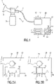
- Fig. 1 shows a schematic view of a breast pump 1 which is suitable for implementation of the inventive features.
- the breast pump 1 comprises an expression kit 2 with an expression kit housing 4.
- a funnel 3, a container 5 and a pipe 7 are connected to the expression kit housing 4.
- the funnel 3 is shaped to be placed on a user's breast to express breast milk therefrom.
- the breast milk is collected in the container 5 which can be connected to the expression kit housing 4 for example by screwing or by a bayonet fixing.
- a venting valve 9 can be provided in the expression kit housing 4 for venting the components during and after expression.
- the expression kit 2 is connected to a drive unit 20 via the pipe 7.
- the drive unit 20 comprises a housing 21 which contains all internal components 22 necessary for operation of the breast pump 1.
- the components 22 comprise at least a pressure unit 6, a control unit 8 and a user interface 10. Other components might be present but are not explicitly referred to.
- “components 22" refers to the entity of components present in the housing 21.
- the pressure unit 6 generally consists of a pump for generating a positive pressure or negative pressure, also called vacuum, in the expression kit 2 and a motor for driving the pump.
- the pressure unit 6 is connected to the housing 21 by way of a suspension 17 as will be described later in more detail.
- the control unit 8 at least a processor 11 is provided for controlling the operation of the pressure unit 6.
- the control unit 8 may comprise for example a storage 12 which can be used to store operational parameters and measured values recorded in connection with the operation of the breast pump 1.
- the user interface 10 may comprise for example a display 13, a speaker 14, a vibrational unit 15 and one or more actuation elements 16.
- the components of the user interface 10 can be used to control the function and the operation of the breast pump 1 for example by way of controlling the pressure via the power of the pump and to give feedback to the user of the breast pump 1 for example by vibrational signals or by audio messages emitted by the speaker 14.
- information about the operational state of the breast pump 1 or about the expressed milk volume in the container 5 can be displayed.
- a general problem of such breast pumps 1 is the generation of noise and vibration when in use.
- the emissions might be annoying for the user.
- the main source for the emissions is the pressure unit 6 with the pump and the driving motor whose noise and vibrations are transferred to the housing 21 via mechanical coupling of the components.
- the emission is then transferred to the housing by way of structure-borne sound.
- High frequencies normally will be filtered out by noise-reducing features as described later on with reference to Fig. 2A .
- mid-range and low frequencies still pass to the housing 21 and will be perceived by the user.
- a drive unit 20 for a breast pump 1 according to the state of the art is briefly described.
- the pressure unit 6 it is known to arrange the pressure unit 6 on a suspension 17 which decouples the noise-generating components from the housing 21.
- FIG. 2B an embodiment of the invention is shown in a similar illustration as in Fig. 2A .
- the drive unit 20 in Fig. 2B is designed to eliminate not only high frequencies but also mid-range frequencies of the noise-generating components.
- the pressure unit 6, but also the control unit 8 and the user interface 10 and possible other components present in the housing 21 are arranged on the suspension 17.
- the total mass of the decoupled components 22 is higher as in Fig. 2A .
- the suspension 17 can be designed in different ways to meet the demands of respective application in the breast pump 1.
- the suspension 17 will comprise at least one resilient element which connects the components 22 to the housing 21.
- the resilient element can be a spring, for example a coil spring or a plate spring, a damping element, a vibration absorber, or an elastomeric element.
- the damping element can be adjustable to tune the frequencies which are eliminated from the frequency spectrum. If an elastomeric element is used, the element may comprise materials like silicone, polyurethane, natural or synthetic rubber, an elastomeric injection molded polymer (TPE) or other applicable resilient materials.
- TPE elastomeric injection molded polymer
- the internal components 22 can be either mounted fixedly or removably on a base structure 23.
- the base structure 23 can be for example a flat element on which the components 22 can be grouped together and fastened.
- the weight of the base structure 23 can contribute to the total mass M.
- a fixed connection has the advantage that vibrations cannot disintegrate the unit.
- a removable arrangement of the components 22 on the base structure 23 allows easy change of components 22 which are out of function.
- the internal components 22 can be fixedly or removably connected to each other.
- the unit can be stabilized and is more resistant to the vibrations of the pressure unit 6.
- the base structure 23 can be omitted and the components 22 suspended directly by the suspension 17.
- a coupling between the components 22 can be any suitable means like gluing, welding, connecting by straps etc.
- Stabilizing elements can be present to avoid disintegration of the unit during handling. Handling of the drive unit 20 will most probably include some tilting and shaking, and an occasional drop of the breast pump 1 or its components could also occur. Stabilizing elements can be for example further resilient elements which thus administrate a double function of decoupling and stabilizing.
- the expression kit 2 of the breast pump 1 is connected to the drive unit 20.
- the connection can be permanent or removable. Due to the fact that the vibrations of the pressure unit 6 can proceed to the expression kit 2 via the pipe 7, the expression kit 2 can be connected to the housing 21 of the drive unit 20 by way of a resilient flange. The flange then can be connected to the pressure unit 6, thus decoupling the expression kit 2 from the vibrations and noise of the pressure unit 6. If the pipe 7 is resilient itself, the expression kit 2 can also be coupled directly to the pressure unit 6, as schematically shown in Fig. 2A and 2B .
- the breast pump 1 can be operated by connection to an external power supply system by way of an electrical line 24. Care should then be taken not to couple the internal components 22 by way of the electrical line 24 to the housing 21. This could be prevented by a duct in the housing 21. Alternatively, the breast pump 1 can be operated by batteries.
- a computer program may be stored/distributed on a suitable medium, such as an optical storage medium or a solid-state medium supplied together with or as part of other hardware, but may also be distributed in other forms, such as via the Internet or other wired or wireless telecommunication systems.
- a suitable medium such as an optical storage medium or a solid-state medium supplied together with or as part of other hardware, but may also be distributed in other forms, such as via the Internet or other wired or wireless telecommunication systems.
Landscapes
- Health & Medical Sciences (AREA)
- Heart & Thoracic Surgery (AREA)
- Life Sciences & Earth Sciences (AREA)
- Animal Behavior & Ethology (AREA)
- Engineering & Computer Science (AREA)
- Anesthesiology (AREA)
- Biomedical Technology (AREA)
- Hematology (AREA)
- Pediatric Medicine (AREA)
- Vascular Medicine (AREA)
- General Health & Medical Sciences (AREA)
- Public Health (AREA)
- Veterinary Medicine (AREA)
- External Artificial Organs (AREA)
- Reciprocating Pumps (AREA)
- Compressor (AREA)
- Food-Manufacturing Devices (AREA)
Applications Claiming Priority (3)
| Application Number | Priority Date | Filing Date | Title |
|---|---|---|---|
| EP16156587 | 2016-02-19 | ||
| PCT/EP2017/052796 WO2017140562A1 (en) | 2016-02-19 | 2017-02-09 | Drive unit for a breast pump and breast pump |
| EP17703171.3A EP3416697B1 (de) | 2016-02-19 | 2017-02-09 | Antriebseinheit für eine brustpumpe und brustpumpe |
Related Parent Applications (2)
| Application Number | Title | Priority Date | Filing Date |
|---|---|---|---|
| EP17703171.3A Division EP3416697B1 (de) | 2016-02-19 | 2017-02-09 | Antriebseinheit für eine brustpumpe und brustpumpe |
| EP17703171.3A Division-Into EP3416697B1 (de) | 2016-02-19 | 2017-02-09 | Antriebseinheit für eine brustpumpe und brustpumpe |
Publications (1)
| Publication Number | Publication Date |
|---|---|
| EP4052736A1 true EP4052736A1 (de) | 2022-09-07 |
Family
ID=55405200
Family Applications (2)
| Application Number | Title | Priority Date | Filing Date |
|---|---|---|---|
| EP17703171.3A Active EP3416697B1 (de) | 2016-02-19 | 2017-02-09 | Antriebseinheit für eine brustpumpe und brustpumpe |
| EP22163489.2A Pending EP4052736A1 (de) | 2016-02-19 | 2017-02-09 | Antriebseinheit für eine milchpumpe und milchpumpe |
Family Applications Before (1)
| Application Number | Title | Priority Date | Filing Date |
|---|---|---|---|
| EP17703171.3A Active EP3416697B1 (de) | 2016-02-19 | 2017-02-09 | Antriebseinheit für eine brustpumpe und brustpumpe |
Country Status (7)
| Country | Link |
|---|---|
| US (1) | US20210187177A1 (de) |
| EP (2) | EP3416697B1 (de) |
| JP (2) | JP7140682B2 (de) |
| CN (1) | CN108697835B (de) |
| BR (1) | BR112018016679A2 (de) |
| RU (1) | RU2735895C2 (de) |
| WO (1) | WO2017140562A1 (de) |
Families Citing this family (3)
| Publication number | Priority date | Publication date | Assignee | Title |
|---|---|---|---|---|
| EP3461513A1 (de) * | 2017-09-27 | 2019-04-03 | Koninklijke Philips N.V. | Pumpenvorrichtung mit einer pumpe und einer gehäuseaufnahme der pumpe |
| EP3482782A1 (de) | 2017-11-14 | 2019-05-15 | Medela Holding AG | Medizinische saugpumpe |
| CN108295325B (zh) * | 2018-02-12 | 2020-10-09 | 绍兴柯桥韩丝针纺有限公司 | 一种压力可调的吸奶器 |
Citations (7)
| Publication number | Priority date | Publication date | Assignee | Title |
|---|---|---|---|---|
| US20010038799A1 (en) | 1995-08-03 | 2001-11-08 | Silver Brian H. | Diaphragm pump and pump for double-breast pumping |
| WO2004112873A1 (en) * | 2003-06-20 | 2004-12-29 | Resmed Limited | Breathable gas apparatus with humidifier |
| US20050168046A1 (en) | 2003-03-26 | 2005-08-04 | Hadi Rod G. | Method and apparatus for dampening vibrations in an assembly of components |
| EP2105151A1 (de) | 2004-09-20 | 2009-09-30 | Medela Holding AG | Membranpumpe mit Entlüftungsventil |
| EP2196229A1 (de) | 2008-12-12 | 2010-06-16 | Koninklijke Philips Electronics N.V. | Motorisierter Kopf für eine Milchpumpe |
| US20120116299A1 (en) | 2009-07-28 | 2012-05-10 | Koninklijke Philips Electronics N.V. | Flexible drive for breast pump |
| CN203763554U (zh) | 2014-01-25 | 2014-08-13 | 郭永风 | 一种电动吸奶器的主机 |
Family Cites Families (14)
| Publication number | Priority date | Publication date | Assignee | Title |
|---|---|---|---|---|
| GB2404590B (en) * | 2003-08-01 | 2005-06-01 | Cannon Rubber Ltd | Powered breast pump |
| US7824363B2 (en) * | 2007-05-04 | 2010-11-02 | Medela Holding Ag | Hands-free breast pump with balanced reciprocating drive |
| US7833190B1 (en) * | 2007-05-17 | 2010-11-16 | Petisamaria Hall | Breast pump |
| US20100094078A1 (en) * | 2008-10-14 | 2010-04-15 | Hygeia Ii Medical Group, Inc. | Device and method for enhancing milk let-down with a breast pump |
| KR101125710B1 (ko) * | 2009-05-20 | 2012-03-27 | 윤경주 | 혼합기를 구비한 원심분리기 |
| EP2392368A1 (de) * | 2010-06-07 | 2011-12-07 | Koninklijke Philips Electronics N.V. | Brustpumpe |
| KR200464240Y1 (ko) * | 2010-06-29 | 2012-12-18 | 주식회사 엠테크놀러지 | 의료용 흡입기의 진동방지장치 |
| DE102012101642A1 (de) * | 2012-02-29 | 2013-08-29 | DüRR DENTAL AG | Saugmaschine mit Gehäuse aus expandiertem Kunststoff |
| KR101546375B1 (ko) * | 2013-11-25 | 2015-08-21 | 주식회사 엠에스제이 | 착유기 |
| CN203577018U (zh) * | 2013-11-30 | 2014-05-07 | 毛素玲 | 一种吸奶器 |
| US20150283311A1 (en) * | 2014-02-07 | 2015-10-08 | Naia Health, Inc. | Method, apparatus, and system for expression of human breast milk |
| RU2691003C2 (ru) * | 2014-06-05 | 2019-06-07 | Конинклейке Филипс Н.В. | Молокоотсос |
| CN204170165U (zh) * | 2014-08-13 | 2015-02-25 | 林荣敏 | 一种吸奶器用静音气泵 |
| US20160067393A1 (en) * | 2014-09-04 | 2016-03-10 | Tylane Barnes | System and method of use for a concealable and reduced noise breast pump |
-
2017
- 2017-02-09 EP EP17703171.3A patent/EP3416697B1/de active Active
- 2017-02-09 JP JP2018543692A patent/JP7140682B2/ja active Active
- 2017-02-09 EP EP22163489.2A patent/EP4052736A1/de active Pending
- 2017-02-09 US US16/077,789 patent/US20210187177A1/en active Pending
- 2017-02-09 WO PCT/EP2017/052796 patent/WO2017140562A1/en not_active Ceased
- 2017-02-09 BR BR112018016679-0A patent/BR112018016679A2/pt not_active Application Discontinuation
- 2017-02-09 CN CN201780011953.XA patent/CN108697835B/zh active Active
- 2017-02-09 RU RU2018132999A patent/RU2735895C2/ru active
-
2022
- 2022-07-05 JP JP2022108428A patent/JP2022136112A/ja active Pending
Patent Citations (7)
| Publication number | Priority date | Publication date | Assignee | Title |
|---|---|---|---|---|
| US20010038799A1 (en) | 1995-08-03 | 2001-11-08 | Silver Brian H. | Diaphragm pump and pump for double-breast pumping |
| US20050168046A1 (en) | 2003-03-26 | 2005-08-04 | Hadi Rod G. | Method and apparatus for dampening vibrations in an assembly of components |
| WO2004112873A1 (en) * | 2003-06-20 | 2004-12-29 | Resmed Limited | Breathable gas apparatus with humidifier |
| EP2105151A1 (de) | 2004-09-20 | 2009-09-30 | Medela Holding AG | Membranpumpe mit Entlüftungsventil |
| EP2196229A1 (de) | 2008-12-12 | 2010-06-16 | Koninklijke Philips Electronics N.V. | Motorisierter Kopf für eine Milchpumpe |
| US20120116299A1 (en) | 2009-07-28 | 2012-05-10 | Koninklijke Philips Electronics N.V. | Flexible drive for breast pump |
| CN203763554U (zh) | 2014-01-25 | 2014-08-13 | 郭永风 | 一种电动吸奶器的主机 |
Also Published As
| Publication number | Publication date |
|---|---|
| RU2018132999A3 (de) | 2020-05-13 |
| CN108697835B (zh) | 2021-05-04 |
| RU2735895C2 (ru) | 2020-11-09 |
| EP3416697B1 (de) | 2022-07-20 |
| JP2022136112A (ja) | 2022-09-15 |
| WO2017140562A1 (en) | 2017-08-24 |
| BR112018016679A2 (pt) | 2018-12-26 |
| RU2018132999A (ru) | 2020-03-19 |
| JP7140682B2 (ja) | 2022-09-21 |
| JP2019506948A (ja) | 2019-03-14 |
| EP3416697A1 (de) | 2018-12-26 |
| CN108697835A (zh) | 2018-10-23 |
| US20210187177A1 (en) | 2021-06-24 |
Similar Documents
| Publication | Publication Date | Title |
|---|---|---|
| US6839443B2 (en) | Bone conduction speaker | |
| JP2022136112A (ja) | 搾乳ポンプのための駆動ユニット及び搾乳ポンプ | |
| EP1740013B1 (de) | Lautsprecherssystem und Lautsprecherbox | |
| KR102686759B1 (ko) | 의료용 흡인 펌프 | |
| US10469963B2 (en) | Suspended components in auditory prostheses | |
| CN102998637B (zh) | 磁共振设备 | |
| CN106878898A (zh) | 包括接收器组件的助听器 | |
| EP4076563B1 (de) | Brustpumpensystem und pumpenanordnung für ein brustpumpensystem | |
| CN114585829B (zh) | 隔音悬架系统 | |
| RU2770249C1 (ru) | Подвеска вентиляторного блока | |
| CN114585828B (zh) | 隔音悬挂系统 | |
| US20080247578A1 (en) | Hearing Aid Receiver With Vibration Compensation | |
| CN110475184A (zh) | 发声装置和移动终端 | |
| KR100621680B1 (ko) | 중량체가 부착된 진동장치 | |
| CN1671247B (zh) | 麦克风装置 | |
| CN106470378B (zh) | 单线圈多音喇叭 | |
| EP4187920A1 (de) | Lautsprecher | |
| JPH0249684A (ja) | 小型電気機器 | |
| JPS6299682A (ja) | 圧縮機の騒音減衰装置 | |
| JP2007142874A (ja) | スピーカシステムおよびスピーカエンクロージャー | |
| JP2007110264A (ja) | スピーカシステムおよびスピーカエンクロージャー |
Legal Events
| Date | Code | Title | Description |
|---|---|---|---|
| PUAI | Public reference made under article 153(3) epc to a published international application that has entered the european phase |
Free format text: ORIGINAL CODE: 0009012 |
|
| STAA | Information on the status of an ep patent application or granted ep patent |
Free format text: STATUS: THE APPLICATION HAS BEEN PUBLISHED |
|
| AC | Divisional application: reference to earlier application |
Ref document number: 3416697 Country of ref document: EP Kind code of ref document: P |
|
| AK | Designated contracting states |
Kind code of ref document: A1 Designated state(s): AL AT BE BG CH CY CZ DE DK EE ES FI FR GB GR HR HU IE IS IT LI LT LU LV MC MK MT NL NO PL PT RO RS SE SI SK SM TR |
|
| STAA | Information on the status of an ep patent application or granted ep patent |
Free format text: STATUS: REQUEST FOR EXAMINATION WAS MADE |
|
| 17P | Request for examination filed |
Effective date: 20230307 |
|
| RBV | Designated contracting states (corrected) |
Designated state(s): AL AT BE BG CH CY CZ DE DK EE ES FI FR GB GR HR HU IE IS IT LI LT LU LV MC MK MT NL NO PL PT RO RS SE SI SK SM TR |
|
| STAA | Information on the status of an ep patent application or granted ep patent |
Free format text: STATUS: EXAMINATION IS IN PROGRESS |
|
| 17Q | First examination report despatched |
Effective date: 20240628 |