EP4053045A1 - Müllbehälter, behälterdeckel und automatischer schneidemechanismus für müllbeutel - Google Patents
Müllbehälter, behälterdeckel und automatischer schneidemechanismus für müllbeutel Download PDFInfo
- Publication number
- EP4053045A1 EP4053045A1 EP21854859.2A EP21854859A EP4053045A1 EP 4053045 A1 EP4053045 A1 EP 4053045A1 EP 21854859 A EP21854859 A EP 21854859A EP 4053045 A1 EP4053045 A1 EP 4053045A1
- Authority
- EP
- European Patent Office
- Prior art keywords
- assembly
- cutting
- garbage
- garbage bag
- cutting assembly
- Prior art date
- Legal status (The legal status is an assumption and is not a legal conclusion. Google has not performed a legal analysis and makes no representation as to the accuracy of the status listed.)
- Withdrawn
Links
- 238000005520 cutting process Methods 0.000 title claims abstract description 134
- 230000007246 mechanism Effects 0.000 title claims abstract description 48
- 230000005540 biological transmission Effects 0.000 claims description 24
- 239000012943 hotmelt Substances 0.000 claims description 6
- 230000007613 environmental effect Effects 0.000 abstract description 3
- 238000010438 heat treatment Methods 0.000 abstract description 3
- 238000007664 blowing Methods 0.000 description 23
- 238000012856 packing Methods 0.000 description 10
- 238000000034 method Methods 0.000 description 4
- 230000009286 beneficial effect Effects 0.000 description 2
- 230000008569 process Effects 0.000 description 2
- 230000035943 smell Effects 0.000 description 2
- 230000013011 mating Effects 0.000 description 1
- 238000012986 modification Methods 0.000 description 1
- 230000004048 modification Effects 0.000 description 1
- 230000005855 radiation Effects 0.000 description 1
- 230000007306 turnover Effects 0.000 description 1
Images




Classifications
-
- B—PERFORMING OPERATIONS; TRANSPORTING
- B26—HAND CUTTING TOOLS; CUTTING; SEVERING
- B26D—CUTTING; DETAILS COMMON TO MACHINES FOR PERFORATING, PUNCHING, CUTTING-OUT, STAMPING-OUT OR SEVERING
- B26D1/00—Cutting through work characterised by the nature or movement of the cutting member or particular materials not otherwise provided for; Apparatus or machines therefor; Cutting members therefor
- B26D1/01—Cutting through work characterised by the nature or movement of the cutting member or particular materials not otherwise provided for; Apparatus or machines therefor; Cutting members therefor involving a cutting member which does not travel with the work
- B26D1/04—Cutting through work characterised by the nature or movement of the cutting member or particular materials not otherwise provided for; Apparatus or machines therefor; Cutting members therefor involving a cutting member which does not travel with the work having a linearly-movable cutting member
- B26D1/06—Cutting through work characterised by the nature or movement of the cutting member or particular materials not otherwise provided for; Apparatus or machines therefor; Cutting members therefor involving a cutting member which does not travel with the work having a linearly-movable cutting member wherein the cutting member reciprocates
- B26D1/08—Cutting through work characterised by the nature or movement of the cutting member or particular materials not otherwise provided for; Apparatus or machines therefor; Cutting members therefor involving a cutting member which does not travel with the work having a linearly-movable cutting member wherein the cutting member reciprocates of the guillotine type
- B26D1/09—Cutting through work characterised by the nature or movement of the cutting member or particular materials not otherwise provided for; Apparatus or machines therefor; Cutting members therefor involving a cutting member which does not travel with the work having a linearly-movable cutting member wherein the cutting member reciprocates of the guillotine type with a plurality of cutting members
-
- B—PERFORMING OPERATIONS; TRANSPORTING
- B26—HAND CUTTING TOOLS; CUTTING; SEVERING
- B26D—CUTTING; DETAILS COMMON TO MACHINES FOR PERFORATING, PUNCHING, CUTTING-OUT, STAMPING-OUT OR SEVERING
- B26D1/00—Cutting through work characterised by the nature or movement of the cutting member or particular materials not otherwise provided for; Apparatus or machines therefor; Cutting members therefor
- B26D1/01—Cutting through work characterised by the nature or movement of the cutting member or particular materials not otherwise provided for; Apparatus or machines therefor; Cutting members therefor involving a cutting member which does not travel with the work
- B26D1/04—Cutting through work characterised by the nature or movement of the cutting member or particular materials not otherwise provided for; Apparatus or machines therefor; Cutting members therefor involving a cutting member which does not travel with the work having a linearly-movable cutting member
- B26D1/06—Cutting through work characterised by the nature or movement of the cutting member or particular materials not otherwise provided for; Apparatus or machines therefor; Cutting members therefor involving a cutting member which does not travel with the work having a linearly-movable cutting member wherein the cutting member reciprocates
- B26D1/10—Cutting through work characterised by the nature or movement of the cutting member or particular materials not otherwise provided for; Apparatus or machines therefor; Cutting members therefor involving a cutting member which does not travel with the work having a linearly-movable cutting member wherein the cutting member reciprocates in, or substantially in, a direction parallel to the cutting edge
- B26D1/11—Cutting through work characterised by the nature or movement of the cutting member or particular materials not otherwise provided for; Apparatus or machines therefor; Cutting members therefor involving a cutting member which does not travel with the work having a linearly-movable cutting member wherein the cutting member reciprocates in, or substantially in, a direction parallel to the cutting edge with a plurality of cutting members
-
- B—PERFORMING OPERATIONS; TRANSPORTING
- B26—HAND CUTTING TOOLS; CUTTING; SEVERING
- B26D—CUTTING; DETAILS COMMON TO MACHINES FOR PERFORATING, PUNCHING, CUTTING-OUT, STAMPING-OUT OR SEVERING
- B26D5/00—Arrangements for operating and controlling machines or devices for cutting, cutting-out, stamping-out, punching, perforating, or severing by means other than cutting
- B26D5/08—Means for actuating the cutting member to effect the cut
- B26D5/086—Electric, magnetic, piezoelectric, electro-magnetic means
-
- B—PERFORMING OPERATIONS; TRANSPORTING
- B26—HAND CUTTING TOOLS; CUTTING; SEVERING
- B26F—PERFORATING; PUNCHING; CUTTING-OUT; STAMPING-OUT; SEVERING BY MEANS OTHER THAN CUTTING
- B26F3/00—Severing by means other than cutting; Apparatus therefor
- B26F3/06—Severing by using heat
- B26F3/08—Severing by using heat with heated members
-
- B—PERFORMING OPERATIONS; TRANSPORTING
- B65—CONVEYING; PACKING; STORING; HANDLING THIN OR FILAMENTARY MATERIAL
- B65B—MACHINES, APPARATUS OR DEVICES FOR, OR METHODS OF, PACKAGING ARTICLES OR MATERIALS; UNPACKING
- B65B31/00—Packaging articles or materials under special atmospheric or gaseous conditions; Adding propellants to aerosol containers
- B65B31/04—Evacuating, pressurising or gasifying filled containers or wrappers by means of nozzles through which air or other gas, e.g. an inert gas, is withdrawn or supplied
- B65B31/041—Evacuating, pressurising or gasifying filled containers or wrappers by means of nozzles through which air or other gas, e.g. an inert gas, is withdrawn or supplied the nozzles acting from above on containers or wrappers open at their top
-
- B—PERFORMING OPERATIONS; TRANSPORTING
- B65—CONVEYING; PACKING; STORING; HANDLING THIN OR FILAMENTARY MATERIAL
- B65B—MACHINES, APPARATUS OR DEVICES FOR, OR METHODS OF, PACKAGING ARTICLES OR MATERIALS; UNPACKING
- B65B51/00—Devices for, or methods of, sealing or securing package folds or closures; Devices for gathering or twisting wrappers, or necks of bags
- B65B51/10—Applying or generating heat or pressure or combinations thereof
-
- B—PERFORMING OPERATIONS; TRANSPORTING
- B65—CONVEYING; PACKING; STORING; HANDLING THIN OR FILAMENTARY MATERIAL
- B65B—MACHINES, APPARATUS OR DEVICES FOR, OR METHODS OF, PACKAGING ARTICLES OR MATERIALS; UNPACKING
- B65B51/00—Devices for, or methods of, sealing or securing package folds or closures; Devices for gathering or twisting wrappers, or necks of bags
- B65B51/10—Applying or generating heat or pressure or combinations thereof
- B65B51/26—Devices specially adapted for producing transverse or longitudinal seams in webs or tubes
- B65B51/30—Devices, e.g. jaws, for applying pressure and heat, e.g. for subdividing filled tubes
- B65B51/303—Devices, e.g. jaws, for applying pressure and heat, e.g. for subdividing filled tubes reciprocating along only one axis
-
- B—PERFORMING OPERATIONS; TRANSPORTING
- B65—CONVEYING; PACKING; STORING; HANDLING THIN OR FILAMENTARY MATERIAL
- B65B—MACHINES, APPARATUS OR DEVICES FOR, OR METHODS OF, PACKAGING ARTICLES OR MATERIALS; UNPACKING
- B65B61/00—Auxiliary devices, not otherwise provided for, for operating on sheets, blanks, webs, binding material, containers or packages
- B65B61/04—Auxiliary devices, not otherwise provided for, for operating on sheets, blanks, webs, binding material, containers or packages for severing webs, or for separating joined packages
- B65B61/06—Auxiliary devices, not otherwise provided for, for operating on sheets, blanks, webs, binding material, containers or packages for severing webs, or for separating joined packages by cutting
-
- B—PERFORMING OPERATIONS; TRANSPORTING
- B65—CONVEYING; PACKING; STORING; HANDLING THIN OR FILAMENTARY MATERIAL
- B65B—MACHINES, APPARATUS OR DEVICES FOR, OR METHODS OF, PACKAGING ARTICLES OR MATERIALS; UNPACKING
- B65B7/00—Closing containers or receptacles after filling
- B65B7/02—Closing containers or receptacles deformed by, or taking-up shape, of, contents, e.g. bags, sacks
- B65B7/06—Closing containers or receptacles deformed by, or taking-up shape, of, contents, e.g. bags, sacks by collapsing mouth portion, e.g. to form a single flap
- B65B7/12—Closing containers or receptacles deformed by, or taking-up shape, of, contents, e.g. bags, sacks by collapsing mouth portion, e.g. to form a single flap and twisting
-
- B—PERFORMING OPERATIONS; TRANSPORTING
- B65—CONVEYING; PACKING; STORING; HANDLING THIN OR FILAMENTARY MATERIAL
- B65B—MACHINES, APPARATUS OR DEVICES FOR, OR METHODS OF, PACKAGING ARTICLES OR MATERIALS; UNPACKING
- B65B9/00—Enclosing successive articles, or quantities of material, e.g. liquids or semiliquids, in flat, folded, or tubular webs of flexible sheet material; Subdividing filled flexible tubes to form packages
- B65B9/10—Enclosing successive articles, or quantities of material, in preformed tubular webs, or in webs formed into tubes around filling nozzles, e.g. extruded tubular webs
- B65B9/15—Enclosing successive articles, or quantities of material, in preformed tubular webs, or in webs formed into tubes around filling nozzles, e.g. extruded tubular webs the preformed tubular webs being stored on filling nozzles
-
- B—PERFORMING OPERATIONS; TRANSPORTING
- B65—CONVEYING; PACKING; STORING; HANDLING THIN OR FILAMENTARY MATERIAL
- B65B—MACHINES, APPARATUS OR DEVICES FOR, OR METHODS OF, PACKAGING ARTICLES OR MATERIALS; UNPACKING
- B65B9/00—Enclosing successive articles, or quantities of material, e.g. liquids or semiliquids, in flat, folded, or tubular webs of flexible sheet material; Subdividing filled flexible tubes to form packages
- B65B9/10—Enclosing successive articles, or quantities of material, in preformed tubular webs, or in webs formed into tubes around filling nozzles, e.g. extruded tubular webs
- B65B9/15—Enclosing successive articles, or quantities of material, in preformed tubular webs, or in webs formed into tubes around filling nozzles, e.g. extruded tubular webs the preformed tubular webs being stored on filling nozzles
- B65B9/18—Devices for storing tubular webs
-
- B—PERFORMING OPERATIONS; TRANSPORTING
- B65—CONVEYING; PACKING; STORING; HANDLING THIN OR FILAMENTARY MATERIAL
- B65F—GATHERING OR REMOVAL OF DOMESTIC OR LIKE REFUSE
- B65F1/00—Refuse receptacles; Accessories therefor
- B65F1/04—Refuse receptacles; Accessories therefor with removable inserts
- B65F1/06—Refuse receptacles; Accessories therefor with removable inserts with flexible inserts, e.g. bags or sacks
-
- B—PERFORMING OPERATIONS; TRANSPORTING
- B65—CONVEYING; PACKING; STORING; HANDLING THIN OR FILAMENTARY MATERIAL
- B65F—GATHERING OR REMOVAL OF DOMESTIC OR LIKE REFUSE
- B65F1/00—Refuse receptacles; Accessories therefor
- B65F1/04—Refuse receptacles; Accessories therefor with removable inserts
- B65F1/06—Refuse receptacles; Accessories therefor with removable inserts with flexible inserts, e.g. bags or sacks
- B65F1/062—Refuse receptacles; Accessories therefor with removable inserts with flexible inserts, e.g. bags or sacks having means for storing or dispensing spare bags
-
- B—PERFORMING OPERATIONS; TRANSPORTING
- B65—CONVEYING; PACKING; STORING; HANDLING THIN OR FILAMENTARY MATERIAL
- B65F—GATHERING OR REMOVAL OF DOMESTIC OR LIKE REFUSE
- B65F1/00—Refuse receptacles; Accessories therefor
- B65F1/14—Other constructional features; Accessories
- B65F1/16—Lids or covers
-
- B—PERFORMING OPERATIONS; TRANSPORTING
- B65—CONVEYING; PACKING; STORING; HANDLING THIN OR FILAMENTARY MATERIAL
- B65B—MACHINES, APPARATUS OR DEVICES FOR, OR METHODS OF, PACKAGING ARTICLES OR MATERIALS; UNPACKING
- B65B67/00—Apparatus or devices facilitating manual packaging operations; Sack holders
- B65B67/12—Sack holders, i.e. stands or frames with means for supporting sacks in the open condition to facilitate filling with articles or materials
- B65B2067/1283—Means for gathering, closing or sealing the sacks
-
- B—PERFORMING OPERATIONS; TRANSPORTING
- B65—CONVEYING; PACKING; STORING; HANDLING THIN OR FILAMENTARY MATERIAL
- B65B—MACHINES, APPARATUS OR DEVICES FOR, OR METHODS OF, PACKAGING ARTICLES OR MATERIALS; UNPACKING
- B65B43/00—Forming, feeding, opening or setting-up containers or receptacles in association with packaging
- B65B43/26—Opening or distending bags; Opening, erecting, or setting-up boxes, cartons, or carton blanks
- B65B43/34—Opening or distending bags; Opening, erecting, or setting-up boxes, cartons, or carton blanks by internal pressure
- B65B43/36—Opening or distending bags; Opening, erecting, or setting-up boxes, cartons, or carton blanks by internal pressure applied pneumatically
-
- B—PERFORMING OPERATIONS; TRANSPORTING
- B65—CONVEYING; PACKING; STORING; HANDLING THIN OR FILAMENTARY MATERIAL
- B65F—GATHERING OR REMOVAL OF DOMESTIC OR LIKE REFUSE
- B65F2210/00—Equipment of refuse receptacles
- B65F2210/126—Cutting means
-
- B—PERFORMING OPERATIONS; TRANSPORTING
- B65—CONVEYING; PACKING; STORING; HANDLING THIN OR FILAMENTARY MATERIAL
- B65F—GATHERING OR REMOVAL OF DOMESTIC OR LIKE REFUSE
- B65F2210/00—Equipment of refuse receptacles
- B65F2210/167—Sealing means
- B65F2210/1675—Sealing means by twisting, e.g. of a flexible tube
-
- Y—GENERAL TAGGING OF NEW TECHNOLOGICAL DEVELOPMENTS; GENERAL TAGGING OF CROSS-SECTIONAL TECHNOLOGIES SPANNING OVER SEVERAL SECTIONS OF THE IPC; TECHNICAL SUBJECTS COVERED BY FORMER USPC CROSS-REFERENCE ART COLLECTIONS [XRACs] AND DIGESTS
- Y02—TECHNOLOGIES OR APPLICATIONS FOR MITIGATION OR ADAPTATION AGAINST CLIMATE CHANGE
- Y02W—CLIMATE CHANGE MITIGATION TECHNOLOGIES RELATED TO WASTEWATER TREATMENT OR WASTE MANAGEMENT
- Y02W30/00—Technologies for solid waste management
- Y02W30/10—Waste collection, transportation, transfer or storage, e.g. segregated refuse collecting, electric or hybrid propulsion
Definitions
- the present disclosure relates to a garbage bin, and in particular to a garbage bin, a bin lid, and an automatic cutting mechanism for garbage bag.
- the technical problem to be solved by the present disclosure is to provide a garbage bin, a bin lid, and an automatic cutting mechanism for garbage bag.
- the technical problem solved by the present disclosure is to provide an automatic cutting mechanism for garbage bag in the garbage bin, comprising a first guiding assembly, a second guiding assembly, a first cutting assembly, a second cutting assembly, and a cutting drive device;
- the first guiding assembly and the second guiding assembly respectively comprise a first guiding rail and a second guiding rail arranged side by side at intervals; the first cutting assembly is extended from the first guiding rail to the second guiding rail, and the second cutting assembly is extended from the second guiding rail to the first guiding rail.
- the first cutting assembly comprises a first support slidably matched with the first guiding rail
- the second cutting assembly comprises a second support slidably matched with the second guiding rail.
- At least one of the first support and the second support is provided with a cutting member, after the first cutting assembly and the second cutting assembly are approached to each other, the cutting member cuts the sealed position.
- the cutting member is detachably arranged on the first support and faces to the second support, and the second support is provided with an avoiding slot corresponding to the cutting member.
- the automatic cutting mechanism further comprises a position switch for setting the position of the first cutting assembly and the second cutting assembly when they are approached, thus the first cutting assembly and the second cutting assembly stop moving after approaching to each other and clamping the seal, and then the cutting member is electrically connected to the power supply for generating heat.
- the cutting member is a hot melt head electrically connected to a power supply, once the seal is clamped, the hot melt head is energized to heat up, so as to fuse and cut the sealed position.
- the cutting drive device comprises a first drive assembly and a second drive assembly for driving the first cutting assembly and the second cutting assembly to move back and forth, respectively.
- the first drive assembly comprises a first driving wheel and a first driven wheel respectively arranged at both ends of the first guiding rail, and a first transmission belt wound between the first driving wheel and the first driven wheel.
- the first transmission belt is connected to the first support, the first driving wheel rotates and drives the first transmission belt to rotate, so that the first transmission belt drives the first support to slide along the first guiding rail;
- the second drive assembly comprises a second driving wheel and a second driven wheel respectively arranged at both ends of the second guiding rail, and a second transmission belt arranged between the second driving wheel and the second driven wheel.
- the second transmission belt is connected with the second support, the second driving wheel rotates and drives the second transmission belt to rotate, so that the second transmission belt drives the second support to slide along the second guiding rail.
- the first drive assembly further comprises a first motor, and a first gear set respectively mashed with the first driving wheel and the first motor, so the first motor drives the first driving wheel to rotate.
- the second drive assembly further comprises a second motor, and a second gear set respectively meshed with the second driving wheel and the second motor, so the second motor drives the second driving wheel to rotate.
- a bin lid of garbage bin comprising the above automatic cutting mechanism for clamping and cutting the twisted seal on an upper end of the garbage bag.
- a garbage bin comprising the above bin lid.
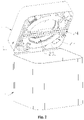
- a garbage bin comprises a bin body 1 and a bin lid 2.
- the bin lid 2 is rotatably arranged on the bin body 1 so as to take out the garbage after being opened.
- the bin lid 2 can be integrated with a complete processing actions of garbage bags, such as storing a garbage bag 3, expanding the garbage bag 3, packing the garbage bag 3, and cutting the garbage bag 3, which are basically automated.
- the bin lid 2 comprises a main body 21 and a lid body 22 rotatably arranged on an upper side of the main body 21, wherein the main body 21 is provided with a rotary packing mechanism 23 and an automatic cutting mechanism 24.
- the lid body 22 is provided with a blowing-expanding mechanism 25 used for blowing air to the garbage bag 3 opened on an annular storage box 231 of the rotary packing mechanism 23 after the lid body 22 is rotated to the main body 21.
- the garbage bag 3 has a long cylindrical shape as a whole after being expanded, and circumference of the garbage bag 3 is placed along the storage box 231 after being axially shrank, and a bottom of a seal of the garbage bag 3 is located at the middle of the storage box 231.
- the garbage bag 3 can be cut into several bag bodies to realize continuous packing, placement and expansion of the garbage bag 3.
- a throw opening is formed at the middle of the storage box 231 for throwing the garbage into the garbage bag 3.
- the annular storage box 231 is used for storing the garbage bags 3 and allows the garbage bags 3 to expand downwards, the blowing-expanding mechanism 25 makes the garbage bags 3 within the storage box 231 to be expanded to the bin body 1, the garbage bag 3 with stored garbage is rotated and packed by the rotary packing mechanism 23, and the seal of the packed garbage bag 3 is cut by the automatic cutting mechanism 24.
- the blowing-expanding mechanism 25 for garbage bag is generally arranged above the storage box 231 and comprises an air blowing member 251 for blowing air to the garbage bag 3 that is open on an upper end of the bin body 1 of the garbage bin, so as to make the garbage bag 3 expand downwards onto inner wall of the bin body 1 of the garbage bin.
- the air blowing member 251 is located above an upper side of the storage box 231, and a blowing direction of the air blowing member 251 is corresponding to an inner circle of the storage box 231.
- the garbage bag is expanded in the manner of the blowing-expanding mechanism blowing air, which expanding method is smart and quick.
- the new garbage bag has not been placed and touched with garbage, which is clean and hygienic, and there will be no peculiar smells flowing during the blowing process, which can reduce the peculiar smells in the environment.
- An air outlet 2511 of the air blowing member 251 has a long strip shape, which can increase a blowing radiation range of the garbage bag 3.
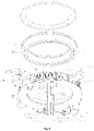
- the blowing-expanding mechanism 25 further comprises a blast chamber 252, the air blowing member 251 is arranged within the blast chamber 252, and the blast chamber 252 is provided with air inlets 2524 for air entering and air blowing ports 2521 for blowing out the air sent by the air blowing member 251.
- the air blast chamber 252 comprises a lower cover 2522 and an upper cover 2523, the air inlets 2524 are formed on a mating surface of the upper cover 2523 and the lower cover 2522, and the air blowing port 2521 are formed on the lower cover 2522.
- the blast chamber 252 is rotatably arranged, so that the lid body 22 drives the entire blowing-expanding mechanism 25 to turn over, thus the garbage can be placed into the garbage bin when the lid body 22 is opened, and the garbage bag 3 can be blew to expand when the lid body 22 is closed.
- the air blowing ports 2521 face to the air outlets 2511, and sizes of the air blowing ports 2521 are not smaller than that of the air outlets 2511.
- a plurality of air blowing members 251 are provided within the blast chamber 252, and a plurality of air blowing ports 2521 respectively corresponding to the air outlets 2511 of each of the air blowing members 251 are provided on the blast chamber 252, so that the air sent by each of the air blowing members 251 is blown out through the air outlets 2521.
- each of the air blowing members 251 is arranged in sequence from end to end to form a semi-closed shape, or a closed shape; or the air outlet 2511 of each of the air blowing members 251 is arranged in the same direction in sequence to form a line shape etc.
- the blowing-expanding mechanism 25 blows air into the storage box 231 to expand the garbage bag 3 downwards to fit with inner walls of the bin body 1 of the garbage bin.
- the lid body 22 can be turned over and opened to dump garbage into the garbage bag 3.
- the rotary packing mechanism 23 comprises a rotary driving device 232 for driving the storage box 231 to rotate.
- the rotary driving device 232 interacts with the storage box 231 to make the storage box 231 and the garbage bags 3 within the storage box 231 rotate relative to the garbage bag 3 with stored garbage.
- the rotation of the storage box 231 makes the garbage bag 3 that is expanded downwards and stored with garbage rotate, whose upper end is then twisted and sealed.
- the rotary driving device drives the storage box to rotate to twist and seal, so the seal is tighter, the garbage inside is not easy to leak, and the seal is small, which is conducive for subsequent automatic cuttings.
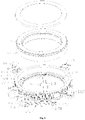
- the rotary driving device 232 comprises a rotatable drive member 2321 for driving the storage box 231 to rotate when the drive member 2321 rotates.
- the drive member 2321 is an annular drive disk which is configured as rotatable and circumferentially positioned on the storage box 231. When the drive disk rotates, the storage box 231 is driven to rotate, thus to twist relative to the underneath garbage bag 3 with stored garbage.
- the drive disk and the storage box 231 are arranged concentrically, the drive disk is engaged with the storage box 231, so that the storage box 231 is driven to rotate when the drive disk rotates.
- the drive disk comprises an annular gear ring 2322, teeth are arranged on an outer ring of the gear ring 2322, and the storage box 231 is located on an inner ring of the gear ring 2322.
- the drive disk further comprises a positioning portion 2323 arranged on the inner ring of the gear ring 2322, and the positioning portion 2323 is provided with an engagement portion 2324 for engaging with the storage box 231.
- the positioning portion 2323 is ring-shaped and arranged along an inner circumference of the gear ring 2322
- the storage box 231 is placed on the positioning portion 2323
- the engagement portion 2324 is a boss protruding upwards on a side for positioning
- grooves 2311 are provided at the bottom of the storage box 231 for inserting the boss.
- a plurality of engagement portions 2324 are provided along the circumference of the positioning portion 2323 for engaging with each of the grooves 2311 at the bottom of the storage box 231 to rotate synchronously.
- an engagement position of the drive disk and the storage box 231 can also be located on an inner wall of the gear ring 2322 and an outer wall surface of the storage box 231, or teeth or other structures are directly arranged on the circumference of the storage box 231, so that the rotary driving device 232 drives the storage box 231 to rotate directly.
- the rotary driving device 232 further comprises a rotary motor 2325 for driving the drive member 2321 to rotate, and a gear set for transmitting outputs of the rotary motor 2325.
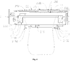
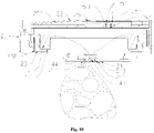
- the automatic cutting mechanism 24 comprises a first guiding assembly 241, a second guiding assembly 242, a first cutting assembly 243, a second cutting assembly 244, and a cutting drive device 245.
- the cutting drive device 245 drives the first cutting assembly 243 to move back and forth along the first guiding assembly 241 and drives the second cutting assembly 244 to move back and forth along the second guiding assembly 242.
- the first cutting assembly 243 and the second cutting assembly 244 are approached and moved away from each other when moving forth and back; when approaching to each other, the twisted seal at the upper end of the garbage bag 3 is clamped and cut, and after moving away from each other, a space is left for the new garbage bag 3 at the upper end to expand downwards.
- the automatic cutting mechanism clamps the twisted and sealed position, a size required be heated will be very short, the required heat is little, and the power consumption is low, thus the environmental protection has been improved.
- the first guiding assembly 241 and the second guiding assembly 242 respectively comprise a first guiding rail 2411 and a second guiding rail 2421 arranged side by side at intervals.
- the first cutting assembly 243 is extended from the first guiding rail 2411 to the second guiding rail 2421
- the second cutting assembly 244 is extended from the second guiding rail 2421 to the first guiding rail 2411, thus the first cutting assembly 243 and the second cutting assembly 244 are arranged in parallel.
- the first cutting assembly 243 comprises a first support 2431 slidably matched with the first guiding rail 2411
- the second cutting assembly 244 comprises a second support 2441 slidably matched with the second guiding rail 2421.
- At least one of the first support 2431 and the second support 2441 is provided with a cutting member 2432, after the first cutting assembly 243 and the second cutting assembly 244 are approached to each other, the cutting member 2432 cuts the sealed position.
- the cutting member 2432 is detachably arranged on the first support 2431 and faces to the second support 2441, and the second support 2441 is provided with an avoiding slot 2442 corresponding to the cutting member 2432. After the garbage bag 3 is twisted and sealed, the sealed position is just corresponding to the position of the cutting member 2432. After the first cutting assembly 243 and the second cutting assembly 244 are approached, the cutting member 2432 abuts on the twisted seal and then cuts it apart.
- the cutting member 2432 is a hot melt head electrically connected to a power supply, once the seal is clamped, the hot melt head is energized to heat up, so as to fuse and cut the sealed position.
- the automatic cutting mechanism 24 further comprises a position switch 246 for setting the position of the first cutting assembly 243 and the second cutting assembly 244 when they are approached, thus the first cutting assembly 243 and the second cutting assembly 244 stop moving after approaching to each other and clamping the seal, and then the cutting member 2432 is electrically connected to the power supply for generating heat to fuse the twisted seal.
- the cutting drive device 245 comprises a first drive assembly 2451 and a second drive assembly 2452 for driving the first cutting assembly 243 and the second cutting assembly 244 to move back and forth, respectively.
- the first drive assembly 2451 comprises a first driving wheel 2453 and a first driven wheel 2454 respectively arranged at both ends of the first guiding rail 2411, and a first transmission belt 2455 wound between the first driving wheel 2453 and the first driven wheel 2454.
- the first transmission belt 2455 is connected to the first support 2431, the first driving wheel 2453 rotates and drives the first transmission belt 2455 to rotate, so that the first transmission belt 2455 drives the first support 2431 to slide along the first guiding rail 2411.
- the first drive assembly 2451 further comprises a first motor, and a first gear set respectively mashed with the first driving wheel 2453 and the first motor, so the first motor drives the first driving wheel 2453 to rotate.
- the second drive assembly 2452 comprises a second driving wheel 2456 and a second driven wheel 2457 respectively arranged at both ends of the second guiding rail 2421, and a second transmission belt 2458 arranged between the second driving wheel 2456 and the second driven wheel 2457.
- the second transmission belt 2458 is connected with the second support 2441, the second driving wheel 2456 rotates and drives the second transmission belt 2458 to rotate, so that the second transmission belt 2458 drives the second support 2441 to slide along the second guiding rail 2421.
- the second drive assembly 2452 further comprises a second motor, and a second gear set respectively meshed with the second driving wheel 2456 and the second motor, so the second motor drives the second driving wheel 2456 to rotate.
- the garbage bin, the bin lid and the automatic cutting mechanism for garbage bag of the present disclosure have the following beneficial effects: the automatic cutting mechanism clamps the twisted seal position, a size required to be heated will be very short, the required heat is little, the heating block and power consumption are low, thus the environmental protection has been improved.
Landscapes
- Engineering & Computer Science (AREA)
- Mechanical Engineering (AREA)
- Life Sciences & Earth Sciences (AREA)
- Forests & Forestry (AREA)
- Chemical & Material Sciences (AREA)
- Dispersion Chemistry (AREA)
- Refuse Receptacles (AREA)
- Package Closures (AREA)
Applications Claiming Priority (1)
| Application Number | Priority Date | Filing Date | Title |
|---|---|---|---|
| PCT/CN2021/071633 WO2022151118A1 (zh) | 2021-01-14 | 2021-01-14 | 垃圾桶及桶盖和垃圾袋自动切割机构 |
Publications (2)
| Publication Number | Publication Date |
|---|---|
| EP4053045A1 true EP4053045A1 (de) | 2022-09-07 |
| EP4053045A4 EP4053045A4 (de) | 2023-06-14 |
Family
ID=78631259
Family Applications (1)
| Application Number | Title | Priority Date | Filing Date |
|---|---|---|---|
| EP21854859.2A Withdrawn EP4053045A4 (de) | 2021-01-14 | 2021-01-14 | Müllbehälter, behälterdeckel und automatischer schneidemechanismus für müllbeutel |
Country Status (5)
| Country | Link |
|---|---|
| US (1) | US20220258902A1 (de) |
| EP (1) | EP4053045A4 (de) |
| JP (1) | JP2023520270A (de) |
| CN (1) | CN214731553U (de) |
| WO (1) | WO2022151118A1 (de) |
Families Citing this family (5)
| Publication number | Priority date | Publication date | Assignee | Title |
|---|---|---|---|---|
| US11618628B2 (en) * | 2021-03-17 | 2023-04-04 | Shannon M. Paul | Personal hygiene product disposal apparatus |
| CN114620370A (zh) * | 2022-02-11 | 2022-06-14 | 宁波金瓴管理咨询有限公司 | 一种防异味垃圾桶盖及垃圾桶 |
| CN116081140B (zh) * | 2023-01-13 | 2024-11-22 | 深圳亿嘉和科技研发有限公司 | 打包装置以及清洁机器人 |
| CN117065903A (zh) * | 2023-10-17 | 2023-11-17 | 烟台科优生物科技有限公司 | 手术室废弃垃圾收集处理装置 |
| CN119975950A (zh) * | 2025-04-14 | 2025-05-13 | 桐乡市伟鼎科技股份有限公司 | 一种笔芯纤维丝抗压紧凑型包装机 |
Family Cites Families (12)
| Publication number | Priority date | Publication date | Assignee | Title |
|---|---|---|---|---|
| JPS4721589Y1 (de) * | 1970-08-25 | 1972-07-15 | ||
| KR100500951B1 (ko) * | 2005-01-28 | 2005-07-11 | 공병원 | 전자동 살균 탈취 쓰레기처리장치 |
| JP4122367B1 (ja) * | 2007-03-28 | 2008-07-23 | 裕美 逸見 | ゴミ箱 |
| GB2520568A (en) * | 2013-11-26 | 2015-05-27 | Alveier Ltd | Sealing apparatus |
| CN104692006B (zh) * | 2015-03-03 | 2017-02-01 | 广州大学 | 智能垃圾桶自动开袋封袋方法及装置 |
| CN206108074U (zh) * | 2016-08-23 | 2017-04-19 | 林华宾 | 一种智能垃圾桶 |
| CN106185105B (zh) * | 2016-08-23 | 2018-07-20 | 珠海方瑞智能科技有限公司 | 一种智能垃圾桶 |
| CN205952784U (zh) * | 2016-08-23 | 2017-02-15 | 林华宾 | 一种垃圾桶磁吸式袋口打开装置及自动套袋系统 |
| CN207242640U (zh) * | 2017-09-29 | 2018-04-17 | 桐乡捷锐建筑材料有限公司 | 抽真空兼自封口垃圾站 |
| ES2877605T3 (es) * | 2018-06-16 | 2021-11-17 | Shanghai Townew Intelligent Tech Co Ltd | Mecanismo de embolsado para bolsas de basura y receptáculos de basura inteligente |
| CN208616605U (zh) * | 2018-08-18 | 2019-03-19 | 程年妹 | 一种自动收口垃圾桶 |
| CN110482066B (zh) * | 2019-08-12 | 2024-03-12 | 深圳麦格米特电气股份有限公司 | 一种自动收缩折叠封口机构和垃圾桶 |
-
2021
- 2021-01-14 WO PCT/CN2021/071633 patent/WO2022151118A1/zh not_active Ceased
- 2021-01-14 EP EP21854859.2A patent/EP4053045A4/de not_active Withdrawn
- 2021-01-14 CN CN202190000032.5U patent/CN214731553U/zh active Active
- 2021-01-14 JP JP2022513894A patent/JP2023520270A/ja active Pending
-
2022
- 2022-02-23 US US17/678,991 patent/US20220258902A1/en not_active Abandoned
Also Published As
| Publication number | Publication date |
|---|---|
| EP4053045A4 (de) | 2023-06-14 |
| US20220258902A1 (en) | 2022-08-18 |
| CN214731553U (zh) | 2021-11-16 |
| JP2023520270A (ja) | 2023-05-17 |
| WO2022151118A1 (zh) | 2022-07-21 |
Similar Documents
| Publication | Publication Date | Title |
|---|---|---|
| US20220258902A1 (en) | Garbage bin, bin lid and automatic cutting mechanism for garbage bag | |
| US20220219891A1 (en) | Garbage bin, bin lid and rotary packing mechanism | |
| US20220219893A1 (en) | Garbage bin, bin lid and blowing-expanding mechanism | |
| US8465404B2 (en) | Container insert apparatus and method | |
| CN209382709U (zh) | 大盖部可拆卸的智能垃圾桶 | |
| CN101948016B (zh) | 全自动塑料导爆管卷绕打把装置 | |
| US3956975A (en) | Packaging method and apparatus | |
| JP5183497B2 (ja) | 流動食品の密封パッケージを製造する折曲げユニット | |
| WO2012080932A1 (en) | Device for vacuum packaging, particularly of food products | |
| US20080295538A1 (en) | Auger in ice bin and refrigerating machine having the same | |
| CN209467619U (zh) | 大盖部可旋转开合的智能垃圾桶 | |
| WO2020152379A1 (es) | Cabezal de flejado automático | |
| CN113060364A (zh) | 建筑用塑料袋封口装置和控制方法 | |
| CN115722844A (zh) | 一种引流式天然气管道焊接用隔断系统及方法 | |
| CN222347456U (zh) | 一种废弃物存储袋打包结构、马桶及垃圾桶 | |
| CN210593553U (zh) | 一种具有自动封口功能的垃圾桶 | |
| JP2020177002A (ja) | 食品パッケージ | |
| CN212862136U (zh) | 一种波纹管自动包装机 | |
| CN107344427A (zh) | 基于吹膜技术的圆底塑料袋生产装置 | |
| WO2009091123A1 (en) | Food waste disposal equipment | |
| CN223632261U (zh) | 一种垃圾袋封口装置及猫砂盆 | |
| CN219728746U (zh) | 一种用于异型包装盒的整面油封装置 | |
| US20070186509A1 (en) | Packing device | |
| TWI905012B (zh) | 複數長條物捲收包裝裝置 | |
| CN110271361B (zh) | 一种自动出料的调色盒 |
Legal Events
| Date | Code | Title | Description |
|---|---|---|---|
| STAA | Information on the status of an ep patent application or granted ep patent |
Free format text: STATUS: UNKNOWN |
|
| STAA | Information on the status of an ep patent application or granted ep patent |
Free format text: STATUS: THE INTERNATIONAL PUBLICATION HAS BEEN MADE |
|
| PUAI | Public reference made under article 153(3) epc to a published international application that has entered the european phase |
Free format text: ORIGINAL CODE: 0009012 |
|
| STAA | Information on the status of an ep patent application or granted ep patent |
Free format text: STATUS: REQUEST FOR EXAMINATION WAS MADE |
|
| 17P | Request for examination filed |
Effective date: 20220324 |
|
| AK | Designated contracting states |
Kind code of ref document: A1 Designated state(s): AL AT BE BG CH CY CZ DE DK EE ES FI FR GB GR HR HU IE IS IT LI LT LU LV MC MK MT NL NO PL PT RO RS SE SI SK SM TR |
|
| A4 | Supplementary search report drawn up and despatched |
Effective date: 20230517 |
|
| RIC1 | Information provided on ipc code assigned before grant |
Ipc: B65F 1/12 20060101ALI20230511BHEP Ipc: B65F 1/06 20060101AFI20230511BHEP |
|
| DAV | Request for validation of the european patent (deleted) | ||
| DAX | Request for extension of the european patent (deleted) | ||
| STAA | Information on the status of an ep patent application or granted ep patent |
Free format text: STATUS: THE APPLICATION IS DEEMED TO BE WITHDRAWN |
|
| 18D | Application deemed to be withdrawn |
Effective date: 20231219 |