EP4053366A1 - Porte coulissante avec aide à l'ouverture - Google Patents
Porte coulissante avec aide à l'ouverture Download PDFInfo
- Publication number
- EP4053366A1 EP4053366A1 EP22159085.4A EP22159085A EP4053366A1 EP 4053366 A1 EP4053366 A1 EP 4053366A1 EP 22159085 A EP22159085 A EP 22159085A EP 4053366 A1 EP4053366 A1 EP 4053366A1
- Authority
- EP
- European Patent Office
- Prior art keywords
- spring
- opening support
- outer sleeve
- carriage
- door leaf
- Prior art date
- Legal status (The legal status is an assumption and is not a legal conclusion. Google has not performed a legal analysis and makes no representation as to the accuracy of the status listed.)
- Granted
Links
Images




Classifications
-
- E—FIXED CONSTRUCTIONS
- E05—LOCKS; KEYS; WINDOW OR DOOR FITTINGS; SAFES
- E05D—HINGES OR SUSPENSION DEVICES FOR DOORS, WINDOWS OR WINGS
- E05D15/00—Suspension arrangements for wings
- E05D15/56—Suspension arrangements for wings with successive different movements
- E05D15/565—Suspension arrangements for wings with successive different movements for raising wings before sliding
-
- E—FIXED CONSTRUCTIONS
- E05—LOCKS; KEYS; WINDOW OR DOOR FITTINGS; SAFES
- E05F—DEVICES FOR MOVING WINGS INTO OPEN OR CLOSED POSITION; CHECKS FOR WINGS; WING FITTINGS NOT OTHERWISE PROVIDED FOR, CONCERNED WITH THE FUNCTIONING OF THE WING
- E05F1/00—Closers or openers for wings, not otherwise provided for in this subclass
- E05F1/08—Closers or openers for wings, not otherwise provided for in this subclass spring-actuated, e.g. for horizontally sliding wings
- E05F1/16—Closers or openers for wings, not otherwise provided for in this subclass spring-actuated, e.g. for horizontally sliding wings for sliding wings
-
- E—FIXED CONSTRUCTIONS
- E05—LOCKS; KEYS; WINDOW OR DOOR FITTINGS; SAFES
- E05F—DEVICES FOR MOVING WINGS INTO OPEN OR CLOSED POSITION; CHECKS FOR WINGS; WING FITTINGS NOT OTHERWISE PROVIDED FOR, CONCERNED WITH THE FUNCTIONING OF THE WING
- E05F5/00—Braking devices, e.g. checks; Stops; Buffers
- E05F5/003—Braking devices, e.g. checks; Stops; Buffers for sliding wings
-
- E—FIXED CONSTRUCTIONS
- E05—LOCKS; KEYS; WINDOW OR DOOR FITTINGS; SAFES
- E05Y—INDEXING SCHEME ASSOCIATED WITH SUBCLASSES E05D AND E05F, RELATING TO CONSTRUCTION ELEMENTS, ELECTRIC CONTROL, POWER SUPPLY, POWER SIGNAL OR TRANSMISSION, USER INTERFACES, MOUNTING OR COUPLING, DETAILS, ACCESSORIES, AUXILIARY OPERATIONS NOT OTHERWISE PROVIDED FOR, APPLICATION THEREOF
- E05Y2201/00—Constructional elements; Accessories therefor
- E05Y2201/40—Motors; Magnets; Springs; Weights; Accessories therefor
- E05Y2201/404—Function thereof
- E05Y2201/422—Function thereof for opening
- E05Y2201/426—Function thereof for opening for the initial opening movement
-
- E—FIXED CONSTRUCTIONS
- E05—LOCKS; KEYS; WINDOW OR DOOR FITTINGS; SAFES
- E05Y—INDEXING SCHEME ASSOCIATED WITH SUBCLASSES E05D AND E05F, RELATING TO CONSTRUCTION ELEMENTS, ELECTRIC CONTROL, POWER SUPPLY, POWER SIGNAL OR TRANSMISSION, USER INTERFACES, MOUNTING OR COUPLING, DETAILS, ACCESSORIES, AUXILIARY OPERATIONS NOT OTHERWISE PROVIDED FOR, APPLICATION THEREOF
- E05Y2201/00—Constructional elements; Accessories therefor
- E05Y2201/40—Motors; Magnets; Springs; Weights; Accessories therefor
- E05Y2201/47—Springs
- E05Y2201/474—Compression springs
-
- E—FIXED CONSTRUCTIONS
- E05—LOCKS; KEYS; WINDOW OR DOOR FITTINGS; SAFES
- E05Y—INDEXING SCHEME ASSOCIATED WITH SUBCLASSES E05D AND E05F, RELATING TO CONSTRUCTION ELEMENTS, ELECTRIC CONTROL, POWER SUPPLY, POWER SIGNAL OR TRANSMISSION, USER INTERFACES, MOUNTING OR COUPLING, DETAILS, ACCESSORIES, AUXILIARY OPERATIONS NOT OTHERWISE PROVIDED FOR, APPLICATION THEREOF
- E05Y2201/00—Constructional elements; Accessories therefor
- E05Y2201/40—Motors; Magnets; Springs; Weights; Accessories therefor
- E05Y2201/499—Spring tensioners; Tension sensors
-
- E—FIXED CONSTRUCTIONS
- E05—LOCKS; KEYS; WINDOW OR DOOR FITTINGS; SAFES
- E05Y—INDEXING SCHEME ASSOCIATED WITH SUBCLASSES E05D AND E05F, RELATING TO CONSTRUCTION ELEMENTS, ELECTRIC CONTROL, POWER SUPPLY, POWER SIGNAL OR TRANSMISSION, USER INTERFACES, MOUNTING OR COUPLING, DETAILS, ACCESSORIES, AUXILIARY OPERATIONS NOT OTHERWISE PROVIDED FOR, APPLICATION THEREOF
- E05Y2201/00—Constructional elements; Accessories therefor
- E05Y2201/60—Suspension or transmission members; Accessories therefor
- E05Y2201/622—Suspension or transmission members elements
- E05Y2201/638—Cams; Ramps
-
- E—FIXED CONSTRUCTIONS
- E05—LOCKS; KEYS; WINDOW OR DOOR FITTINGS; SAFES
- E05Y—INDEXING SCHEME ASSOCIATED WITH SUBCLASSES E05D AND E05F, RELATING TO CONSTRUCTION ELEMENTS, ELECTRIC CONTROL, POWER SUPPLY, POWER SIGNAL OR TRANSMISSION, USER INTERFACES, MOUNTING OR COUPLING, DETAILS, ACCESSORIES, AUXILIARY OPERATIONS NOT OTHERWISE PROVIDED FOR, APPLICATION THEREOF
- E05Y2201/00—Constructional elements; Accessories therefor
- E05Y2201/60—Suspension or transmission members; Accessories therefor
- E05Y2201/622—Suspension or transmission members elements
- E05Y2201/684—Rails; Tracks
-
- E—FIXED CONSTRUCTIONS
- E05—LOCKS; KEYS; WINDOW OR DOOR FITTINGS; SAFES
- E05Y—INDEXING SCHEME ASSOCIATED WITH SUBCLASSES E05D AND E05F, RELATING TO CONSTRUCTION ELEMENTS, ELECTRIC CONTROL, POWER SUPPLY, POWER SIGNAL OR TRANSMISSION, USER INTERFACES, MOUNTING OR COUPLING, DETAILS, ACCESSORIES, AUXILIARY OPERATIONS NOT OTHERWISE PROVIDED FOR, APPLICATION THEREOF
- E05Y2201/00—Constructional elements; Accessories therefor
- E05Y2201/60—Suspension or transmission members; Accessories therefor
- E05Y2201/622—Suspension or transmission members elements
- E05Y2201/686—Rods, links
-
- E—FIXED CONSTRUCTIONS
- E05—LOCKS; KEYS; WINDOW OR DOOR FITTINGS; SAFES
- E05Y—INDEXING SCHEME ASSOCIATED WITH SUBCLASSES E05D AND E05F, RELATING TO CONSTRUCTION ELEMENTS, ELECTRIC CONTROL, POWER SUPPLY, POWER SIGNAL OR TRANSMISSION, USER INTERFACES, MOUNTING OR COUPLING, DETAILS, ACCESSORIES, AUXILIARY OPERATIONS NOT OTHERWISE PROVIDED FOR, APPLICATION THEREOF
- E05Y2800/00—Details, accessories and auxiliary operations not otherwise provided for
- E05Y2800/10—Additional functions
- E05Y2800/12—Sealing
-
- E—FIXED CONSTRUCTIONS
- E05—LOCKS; KEYS; WINDOW OR DOOR FITTINGS; SAFES
- E05Y—INDEXING SCHEME ASSOCIATED WITH SUBCLASSES E05D AND E05F, RELATING TO CONSTRUCTION ELEMENTS, ELECTRIC CONTROL, POWER SUPPLY, POWER SIGNAL OR TRANSMISSION, USER INTERFACES, MOUNTING OR COUPLING, DETAILS, ACCESSORIES, AUXILIARY OPERATIONS NOT OTHERWISE PROVIDED FOR, APPLICATION THEREOF
- E05Y2900/00—Application of doors, windows, wings or fittings thereof
- E05Y2900/10—Application of doors, windows, wings or fittings thereof for buildings or parts thereof
Definitions
- the subject matter of the invention is a lowering sliding door with an opening support according to the preamble of patent claim 1.
- Lowering sliding doors especially sliding doors that close hermetically or on three sides, are lowered in the last few millimeters of travel down to the floor and to the frame, so that a circumferential seal attached to the door comes into contact with the frame with slight contact pressure.
- the door leaf With a sliding door, the door leaf can be moved linearly to close a door opening. Due to the desired low friction and to prevent wear when sliding, the door leaf has a gap to the fixed parts.
- the door leaf In the case of a hermetically sealed sliding door, the door leaf is provided with a circumferential seal. In order for the sealing effect to take place, the door leaf must be lowered at the end of the movement on the one hand and pressed against the frame on the other. This is done, for example, by means of a specially shaped running rail or a running rail with inserted lowering links, which steer the rollers, to which the door leaf is attached via a carriage, in the desired direction at the right time.
- Hermetically sealing doors are usually designed as single-leaf systems, although double-leaf systems are also possible in principle.
- Hermetically sealed doors can be very heavy, such as in hospitals where lead is often incorporated into the door panels to protect against X-rays.
- a compensation of the door weight is also necessary for a powerless emergency opening, since the door has to be opened manually if the power supply fails.
- a sliding door weighing 300 kg which is in the lowering gates when closed, must be able to be opened manually in the event of a power failure.
- a force of max. 220 Newtons must be applied in order to push the door with the rollers out of the individual lowering links of the rail in the opening direction.
- the lowering has a disadvantageous effect on the opening movement in that, in order to overcome it, a force that is higher than that of a linear sliding movement must be overcome.
- This force must be applied by a drive system or a person. It depends on the weight of the door leaf and the shape of the link and cannot always be applied manually by a single person without support. Therefore, with heavier door weights, hand levers are used attached to the door leaf, which allow an increase in the manually applied force acting on the door leaf by utilizing leverage.
- the disadvantage of a version with a hand lever is the size of the lever and that it is attached (usually on both sides) above. Also, for the typical hospital application, the lever must be made of stainless steel, which increases costs.
- the design For operation with a drive system, the design must be based on the increased opening force.
- the corresponding components, such as the motor, control and power supply must be dimensioned larger, which increases the dimensions, costs and, in each case, also the power consumption for a short time.
- the DE 297 13 823 U1 shows a sliding door system that allows the sliding door to be opened with reduced force.
- the guide rail for the roller running gear has a lowering guide in the closed position of the door leaf, into which the door leaf can only be transferred by the roller running gear by charging an energy accumulator.
- the force released when driving into the lowering gate is absorbed by a force accumulator, which also supports the opening movement when the door is opened later.
- This device therefore has the advantage that the total weight of the door leaf does not have to be lifted out of the lowering guide when it is opened.
- the lowering gate shown here is designed as a trough in the guide rail and has the effect that the door leaf is in a lower position in the closed position than in the open position.
- the lowering guide can have a flank that slopes down towards the door opening on one side and in which the trough is formed. This configuration has the effect that the door leaf is also moved in the direction of the door opening. This additional spatial displacement of the door leaf allows elastic seals assigned to the side edges and the upper edge of the door leaf to be brought into effect.
- the force accumulator shown here is a spring which acts on a lever lying in the movement path of the roller drive in the opening direction of the door leaf.
- the roller running gear hits the lever with a driver and pivots it while tensioning the spring.
- the movement into the lowering gate acts on the spring tension in particular.
- a disadvantage of this device is the vulnerable lever arm of the force accumulator, which must always be actuated in conjunction with the spring, with the pivot points of the arm segments being susceptible to wear.
- it is difficult to set a precisely defined opening force because—due to the lever arm—there are several degrees of freedom, which make setting difficult.
- the invention is therefore based on the object of designing an opening support in such a way that, due to a simplified mechanism and optimized lowering link, there is improved response behavior of the energy store and better adjustment options, so that the force for the entire opening movement is as close as possible to that of a linear displacement of the door leaf the rail is approaching.
- An advantageous feature is that to charge the energy accumulator, the door leaf or the carriage, when transferred to the lowering link, acts on a thrust unit that is in the direction of movement of the roller and guided parallel to the direction of travel, which compresses the energy accumulator, which is also aligned parallel to the direction of travel.
- the thrust unit is taken along by the moving part of the sliding door in the closing direction, which is, for example, the carriage or the door leaf and with of the thrust unit comes into contact during the closing movement.
- the reverse principle that the push unit is fixed relative to the movable part of the sliding door and only the stop interacting with the push unit is moved, is also covered by the present invention.
- Such an opening support can be used for any sliding door that can be lowered.
- an effect of the movement via the lowering links is no longer perceived as a hindrance and the drive system does not have to be strengthened either.
- a spring (preferably a helical compression or tension spring) acts on the door leaf in the longitudinal direction of the running rail in the area of the lowering link. Since the spring force of conventional springs increases linearly with the spring deflection, the ideal lowering link is shaped in such a way that the force required to bring the door leaf out of the lowering changes as linearly as possible with the slope, which is identical to the spring rate, and the resulting force for the displacement of the The door leaf thus remains constant within the scope of the friction on the straight route. This is achieved in that the tangent of the gradient angle of the lowering gate changes linearly over the track.
- the lowering gate can be further optimized by taking into account the increased friction caused by the scraping and compression of the seal shortly before the end position.
- the spring rate must be adjusted for different door leaf weights in order to keep the opening force constant.
- all known methods for adjusting a spring rate are suitable for this.
- the simplest method is to choose a spring that is adapted to the door leaf weight from a range of, for example, 3 different sizes.
- the lowering setting must change in return (tangent of the pitch angle). So the profile shape of the lowering can be designed so that the interaction with the The lift mechanism with a linear spring characteristic that is suitable for the door weight works optimally.
- the opening aid is placed in an area of the door where it is not visible to the door user, preferably near the normally covered track.
- the carriage on which the additional roller is suspended also moves in the z-direction and/or y-direction.
- a spring is preferably tensioned as an energy accumulator, with this spring force counteracting the weight of the door leaf. This opposing force partially compensates for the weight of the door and is used to assist opening.
- a spring there can also be other energy accumulators, such as a helical spring, a gas pressure spring, an elastomer accumulator, a hydraulic accumulator, a compressed air accumulator or any other spring body that provides a spring force.
- energy accumulators such as a helical spring, a gas pressure spring, an elastomer accumulator, a hydraulic accumulator, a compressed air accumulator or any other spring body that provides a spring force.
- any type of spring with a preferably approximately linear characteristic can be used.
- compression spring helical spring
- Compression springs store and transmit forces through changes in shape.
- the spring constant can be changed via the spring geometry and material selection.
- the compression spring is loaded by compressing the ends, with the force being introduced via the end coils. The stored energy is partially released when the spring relaxes and is therefore suitable as an opening support.
- the thrust unit which causes the energy accumulator to be charged, is formed by a plunger and in the second embodiment by a thrust bracket.
- the thrust unit comprises a spring guide rod and a ram, which is firmly connected to the spring guide rod, in order to charge the energy accumulator.
- the opening aid is placed in an area of the door where it is not visible to the door user, preferably near the normally covered track.
- the energy accumulator is formed by a helical spring which is clamped between two legs of the housing of the opening support and coaxially surrounds the spring guide rod.
- the guide rod has a projection that radially increases the diameter of the guide rod, which is preferably formed by a nut screwed onto the outer circumference of the guide rod, which rests against the spring start of the helical spring and compresses it in the direction of the opposite leg.
- the energy that is transmitted by the carriage or the door leaf is stored by the elastic helical spring, which serves to compensate for the door weight.
- the preload of the helical spring can be adjusted and varied by the nut.
- a coaxial sleeve body surrounds the plunger in the longitudinal direction at a radial distance.
- the plunger which protrudes from the spring assembly and hits the stop, is designed in such a way that it absorbs the deflection of 5mm in each of the two directions specified by the lowering link by deforming it as a flexible rod or by being attached to the spring assembly articulated in the spring guide rod.
- Such deflections are possible due to the storage within the sleeve body, but are also limited by the rigid sleeve body from a certain degree, so that there is always an almost linear transmission of force to the force accumulator.
- the spring guide rod is guided and supported by sliding bearings which are arranged in the legs and are opposite one another and which allow the end of the spring guide rod opposite the plunger to emerge from the housing in pieces. Since the lateral forces are low, the spring guide rod can be guided axially in plastic plain bearings.
- the spring pack and the stop are constructed symmetrically so that the identical parts can be used for right-hand and left-hand doors.
- the entire weight range of 80-300kg of the usual door leaves can be covered by means of a gradation of, for example, 3 different springs, each with the same spring diameter but different wire cross-section, so that the actuating force remains below 220N.
- any type of spring with a preferably approximately linear characteristic can be used.
- the energy accumulator in the opening support according to the first embodiment can either be attached to the fixed part of the door frame or to the door leaf (or to the carriage) while the stop is located on the opposite side.
- the position of the stopper can be shifted so that the stopper and plunger engage later and so that the coil spring only becomes active in the lower lowering range.
- the push unit is formed by a push tab and the coil spring is mounted inside an outer sleeve connected to the push tab, one end of the spring being coupled to the outer sleeve and the other end of the coil spring resting against the housing of the opening support.
- the energy that is transmitted by the carriage or the door leaf is stored by the elastic helical spring, which serves to compensate for the door weight.
- the outer sleeve has two diametral slot guides through which a bolt is guided, against which the spring end rests inside the outer sleeve.
- the housing of the opening support is U-shaped and has two legs projecting in the direction of the running rail, between which an inner sleeve is held, on which the outer sleeve is arranged concentrically and displaceably.
- the inner sleeve also has two diametral slot guides through which the bolt inserted through the outer sleeve is guided.
- the lateral surface of the outer sleeve has an external thread in the area of the slot guide, onto which an adjusting ring is screwed, which rests on the bolt protruding from the outer sleeve.
- the preload of the coil spring can be finely adjusted and varied using the adjusting ring, so that the maximum permissible sliding force of the door leaf of 220N is not exceeded at any point during the lowering process.
- the adjusting ring also serves to mount the coil spring without play, since the spring body must immediately act on the first tenth of a millimeter for compensation.
- the push tab is plate-shaped and has a recess approximately in the middle, through which the outer sleeve is guided.
- the inner circumference of the recess has a thread in order to screw the push tab onto an external thread in the outer surface of the outer sleeve.
- the position of the push tab can be changed in the direction of the opening movement, so that the carriage and the push tab engage later and the coil spring becomes active later.
- the opening support according to the invention is also suitable for contact with other moving parts of the sliding door, such as the door leaf.
- the push-plate has two pins that project vertically upwards, between which a tie rod mounted between the legs of the housing is guided.
- the tie rod protrudes through a passage in a leg and is coupled via this extension to a tension spring, which cushions an arc-shaped movement of the tie rod about the longitudinal axis of the outer sleeve.
- a tension spring which cushions an arc-shaped movement of the tie rod about the longitudinal axis of the outer sleeve.
- Such a connection of the tie rod can also be attached to both legs of the housing.
- At least two lowering links are preferably used so that a carriage equipped with two rollers can move into a respective lowering link with both rollers at the same time.
- a push plate is used, which is taken along by at least one movable part of the sliding door in the closing direction.
- the energy store is inactive.
- the push plate comes into contact with the carriage.
- the present invention is not limited to this and the push-plate can also come into contact with the carriage somewhat before or after the running rollers of the carriage enter the lowering link.
- the carriage only rests against the drawer bracket and remains in contact with it even when the door leaf is lowered.
- the door leaf mass is thus compensated for by the helical spring due to the opening support according to the invention according to the first and second embodiment. This is achieved by charging the energy accumulator through the slide strap and counteracting this force with the force of weight.
- the opening support there is no need for a complex hand lever system.
- the opening support according to the invention it is also possible to save electrical energy which would be required to move the door out of the connecting link in the x-direction.
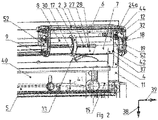
- figure 1 shows a view of the opening support 1 according to the invention, according to the second embodiment of the invention, in the unloaded state.
- the helical spring 3 is in the 0 position, in which the helical spring 3 is not loaded in addition to being prestressed and has the spring length 43 .
- the opening support 1 consists of a U-shaped housing 2 in which the coil spring 3 is installed and which is suspended from a profile 11 above the sliding door.
- the helical spring 3 extends parallel to the running rail 5 and is mounted in an inner sleeve 8 which is suspended between the legs 12, 22 of the U-shaped housing 2.
- the legs 12, 22 each have a recess 52, in which the ends of the inner sleeve 8 are accommodated, the recesses 52 being closed to the outside by the covers 9, 19.
- the covers 9, 19 rest on the outer surface of the legs 12, 22 and are screwed to them via the screw connection 32.
- the inner sleeve 8 is surrounded in sections by a concentric outer sleeve 7 that is movable relative to the inner sleeve 8 and whose length is approximately three-fifths of the inner sleeve 8 .
- the coil spring 3 rests with its spring end 23 opposite the opening movement of the sliding door on a bolt 33 which is inserted diagonally through both sleeves 7, 8.
- the other end of the spring 13 rests on the inside of the cover 19, or if there is an embodiment without a cover, on the inside of the leg 12. The spring is thus clamped between these two points, with the spring end 23 moving in the direction of compression of the spring of the spring end 13 moves.
- an adjustment ring 17 is mounted on the outer circumference of the sleeve 7 and rests on the bolt 33, which protrudes radially from the sleeve 7. This adjustment ring 17 can be moved along the longitudinal axis of the sleeve 7 in order to thus adjust the position of the bolt 33 relative to the sleeve 7 .
- a push tab 4 is fixed, which preferably takes the carriage of the outer sleeve 7 in the direction of the leg 12 when acted upon by a movable part of the sliding door. Since the spring end 23 is also connected to the outer sleeve 7 via the bolt 33 and the adjusting ring 17, the spring end 23 is also moved in the direction of the leg 12 and the helical spring 3 is thus compressed.
- the slide tab 4 protrudes below the outer sleeve 7 between the two legs 12, 22 from the opening support 1 in the direction of the running rail 5.
- the push plate 4 In the opposite direction, ie above the outer sleeve 7, the push plate 4 has two pins 24a, 24b which project vertically upwards and which are arranged in the manner of a fork and receive a tie rod 6 between them.
- the push plate 4 attached to the outer sleeve 7 slides with its pins 24a, 24b along the tie rod 6.
- the two pins 24a, 24b are screwed together via a screw connection 44, which is outside of the opening support 1 can be actuated.
- the tie rod 6 itself is clamped between the two legs 12 , 22 and protrudes through a passage 56 from the right-hand leg 12 .
- this extension 58 there is a notch 16 on which a spring 26 is suspended, the other end of which is suspended from a pin 36 which also protrudes from the leg 12 .
- the pin 36 is fixed.
- the running rail 5 has areas with different profiles in its longitudinal extension, which direct the rollers 30 of a carriage 40 in a direction deviating from the x-direction (arrow 39), such as in the y-direction (arrow 48) or in the z-direction ( direction of arrow 38). These areas are referred to as lowering link 15 and have a depth that deviates from the horizontal, straight running surface. Thus, a roller 30 moves downwards in arrow direction 38 (z-direction) and/or laterally in arrow direction 48 (y-direction) by the distance of depth 41 when entering lowering guide 15 .
- figure 2 shows the outer sleeve 7 , which has the adjusting ring 17 on its end facing the leg 22 , which is screwed onto an external thread 27 which is introduced into the lateral surface 57 of the outer sleeve 7 .
- the outer sleeve 7 has two diametral slot guides 47 which penetrate the lateral surface 57 and are open in the direction of the leg 22 .
- the length of the slot guides 47 is between one third and one half of the length of the outer sleeve 7, the thread 27 also being introduced into the lateral surface 57 at approximately this length.
- a bolt 33 is inserted through the two diametrically opposite slot guides 47 , the ends of which protrude beyond the lateral surface 57 .
- the inner sleeve 8 in which the coil spring 3 is mounted, also has two diametrically opposed slotted guides 28 which are located in the lateral surface of the sleeve 8 and are overlapped in sections by the slotted guides 47 of the outer sleeve 7 .
- a bolt 33 inserted through the slot guides 47 also penetrates the slot guides 28 of the inner sleeve 8.
- the coil spring 3 rests with its spring end 23 on the bolt 33 , the opposite spring end 13 resting on the inside of the cover 19 .
- the helical spring is clamped between these two points.
- the bolt 33 mounted in the partially overlapping slotted guides 28, 47 is held in the direction of the opening of the slotted guide 28, which is located on the end face of the outer sleeve 7 in the direction of the leg 22, by the adjusting ring 17, which fits onto the external thread 27 of the sleeve is screwed on.
- the bolt 33 protruding from the slot guides 28, 47 is in direct contact with the adjusting ring 17 and is moved when the adjusting ring 17 is screwed in along the thread of the external thread 27, i.e. in the longitudinal direction of the outer sleeve 7, in the direction of the leg 12.
- the push lug 4 Attached to the side of the outer sleeve 7 opposite the adjusting ring 17 is the push lug 4 which is screwed onto an external thread 37 .
- the push tab 4 is plate-shaped and has an approximately central recess 42 through which the outer sleeve 7 is guided.
- the inner circumference of Recess 42 has a thread in order to screw the push plate 4 onto the external thread 37 in the lateral surface 57 of the outer sleeve 7 .
- figure 3 also shows a carriage 40 on which a door leaf 10 is suspended.
- the carriage 40 can be moved via the roller 30 on the running rail 5 in the direction of the arrow 39 (x-direction).
- the carriage 40 with the roller 30 is retracted into the lowering link 15 .
- the carriage has moved downwards by the distance 41 in the direction of the arrow 38 (z-direction) and the push-tab 4 has been pressed in the direction of the arrow 39 (x-direction).
- the rolling of the roller 30 into this lowering guide means that the door panel 1 mounted on the carriage 40 is also moved by the distance 41 in the direction of the arrow 38 .
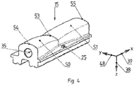
- figure 4 shows the lowering gate 15, which has a profile shape that differs from the straight running rail 5, with which the movement of the running roller 30 is controlled.
- the roller 30 of the carriage 40 has a wedge-shaped guide groove to roll on the guide rail 5 .
- the lowering link has one or more recesses 35 with which it can be aligned with the running rail 5 and connected.
- the lowering link has the low point 53 in the middle, which represents the last possible end position of the roller 30 when entering the lowering link 15, in which the sliding door has reached its maximum lowering.
- the end points 54 and 55 represent the beginning of the geometry of the lowering link 15, which deviates from the straight guide rail 5, these points still being on the height profile of the guide rail 5 and on the x-axis (arrow direction 39).
- a flank 50 falls in the direction of the low point 53 in the direction of the arrow 38.
- a flank 51 with the opposite slope of the flank 50 falls in the direction of the low point 53 in the direction of the arrow 38.
- both flanks unite at the low point 53.
- the two flanks 50, 51 are slightly inclined, since the low point 53 is not located exactly between the two end points 54, 55, but is at a distance in the direction of arrow 48 from the connecting axis of the end points.
- a roller 30 rolling over the flanks would thus be deflected not only in the direction of the arrow 38 but also in the direction of the arrow 48 until the low point 53 is reached and the roller no longer rolls any further.
- a guide mandrel 25 which laterally guides a roller that can be moved on the lowering link.
- figure 5 shows a perspective view of the opening support 1, in the charged state.
- the push tab 4 is located close to the leg 12 and the helical spring is compressed to the length 43'.
- the tie rod 6 is guided with play through the passage 56 of the leg 12 and protrudes with the extension 58 from the leg.
- This extension has the notch 16 on which the end of the tension spring 26 is hooked, the other end of which is connected to the pin 36 which also protrudes from the leg 12 and is fixed to it.
- figure 6 shows a rotated view of figure 5 , where the same or equivalent parts are denoted by the same reference numerals.
- figure 7 shows a sectional view of the opening support 1, from which the compression of the coil spring 3 by the bolt 33 can be seen.
- the helical spring 3 rests with its end 23 on the bolt 33 and is compressed by the latter in the direction of the arrow 39 since a movement of the push plate 4 is transmitted to the bolt 33 via the sleeve 7 and the adjusting ring 17 .
- the slide bracket 4 is held in this position by the carriage 40, which transfers the weight of the sliding door to the slide bracket due to the entry into the lowering link.
- figure 8 shows section VII-VII figure 7 , wherein it can be seen that the housing 2 can be attached via the bracket 31.
- the push plate 4 experiences not only a movement in the direction of the arrow 39 (x-direction), but also a pivoting movement about the central axis 46 of the coil spring in the direction of the arrow 49. This is due to the non-positive contact of the carriage with the Drawer flap 4.
- the vertical longitudinal axis 29 runs through the push tab, which is pivoted by the angle 34 in the direction of the arrow 49 and is present in the new position as the longitudinal axis 29'.
- FIG 9 shows a perspective view of the first embodiment of the invention.
- a plunger 64 is firmly connected to a spring guide rod 65, which is mounted on two plain bearings 60, 61 within the housing 2a.
- the two plain bearings 60, 61 are fitted into bores in the legs 74, 75 and enable the spring guide rod 65 to be guided through in the longitudinal direction.
- the side of the spring guide rod 65 in which the plunger 64 is introduced protrudes laterally from the housing 2a so that the plunger 64 is aligned in the direction of the stop 68 .
- the plunger 64 comes into contact with the stop 68 , the plunger and the spring guide rod 65 firmly connected to it are moved in the direction of the arrow 39 .
- This movement also moves the nut 62, which is firmly connected to the spring guide rod 65 and rests on the spring start 66, in the direction of arrow 39 and compresses the coil spring 63, which has its spring end 67 on the leg 75 inside the housing 2a.
- the spring guide rod 65 which is mounted in the leg 75 by means of the outwardly open plain bearing 61, penetrates the plain bearing in the direction of arrow 39 and, depending on the distance covered and spring characteristic, protrudes from the leg 75 out of the housing 2a.
- the coil spring 63 is thus moved only by the nut 62, the spring guide rod, the diameter of which is smaller than the inner diameter of the coil spring 63, runs inside the spring.
- the stop 68 which in the example shown has a head as a contact surface and an elongate screw body 78 adjoining it, is fastened in a bore of a bracket 59 running perpendicularly to the screw body.
- the hole in the lug is surrounded by a nut 73 which is firmly connected to the lug 59 and through which the screw body 78 can be screwed, as a result of which an adjustment of the stop in the axial direction is possible.
- the position of the stop 68 can be adjusted in the displacement path of the door leaf.
- figure 10 shows a side view of the housing 2a with the leg 75 to which the sliding bearing 61 is screwed via the screw connection 82.
- the slide bearing 61 is held by a flange 83, at the wing-shaped ends of which the screw connection 82 is carried out.
- a slide bearing 60 of the same type and mounted in the same way is also present on the ram side of the housing 2a.
- Figure 12 shows a sectional view along the XI-XI axis figure 10 .
- the spring guide rod 65 is mounted in the two sliding bearings 60, 61 and can be displaced in the longitudinal direction.
- the spring guide rod 65 is in two parts and consists of a solid rod 69 with a bore 72 on the end face, into which the rod-shaped plunger 64 is inserted.
- the plunger 64 is preferably glued in the bore 72 .
- the sleeve body 70 rests flush against the end face of the rod 69 in the axial direction and has the same outer diameter as the rod 69 and forms the spring guide rod 65 with the rod 69 .
- both round bodies have an external thread 71, 79 onto which a nut 62 is screwed.
- the spring guide rod 65 has the external thread 79 and the sleeve body has the external thread 71.
- the nut 62 thus engages over both parts of the spring guide rod and the threaded engagement means that both parts 69, 70 are connected to one another and can move with one another.
- the rod 69 has at its other end an axial bore 81 with an internal profile in which a tool can engage to rotate the spring guide rod 65 and thus to the threaded connection of Nut 62 to act with the external threads 71, 79 of the rod 69 and sleeve body 70.
- the opening support 1 also consists of a U-shaped housing 2a in which the coil spring 63 is installed and which is suspended from a profile above the sliding door.
- the coil spring 63 extends parallel to the running rail and is suspended between the legs 74, 75 of the U-shaped housing 2a.
- the legs 74, 75 each have a bore 76, 77 in which the spring guide rod 65 is accommodated, with a plain bearing 60, 61 being inserted in the bores 76, 77, i.e. between the inner diameter of the bore and the outer diameter of the spring guide rod 65. which allows displacement of the spring guide rod 65 in the longitudinal direction relative to the housing 2a.
- the helical compression spring 63 rests with its rear end 67 on the inside of the leg 75 and with its front end 66 on the nut 62.
- the helical compression spring 63 guides the rod 69, on the front end of which the nut 62 is screwed.
- the rod 69 moves in the longitudinal direction relative to the housing 2a, the helical compression spring 73 resting between the leg 75 and the nut 62 is compressed.
- the plunger 64 can also absorb lateral forces due to its deformability as a flexible rod, which occur between the stop and the plunger due to the difference in height and side of the lowering link relative to the running rail. Due to the articulated and concentric mounting of the ram 64 within the sleeve body 70, the inside diameter of which is larger than the outside diameter of the ram, deflections of 5 mm each in the direction of the arrows 38 and 48 can be absorbed and compensated, which always results in a linear transmission of force between the stop 68 and the spring guide rod 65 and thus on the coil spring 63 is ensured.
Landscapes
- Engineering & Computer Science (AREA)
- Mechanical Engineering (AREA)
- Closing And Opening Devices For Wings, And Checks For Wings (AREA)
Applications Claiming Priority (1)
| Application Number | Priority Date | Filing Date | Title |
|---|---|---|---|
| DE102021104797.8A DE102021104797A1 (de) | 2021-03-01 | 2021-03-01 | Öffnungsunterstützung |
Publications (2)
| Publication Number | Publication Date |
|---|---|
| EP4053366A1 true EP4053366A1 (fr) | 2022-09-07 |
| EP4053366B1 EP4053366B1 (fr) | 2026-04-01 |
Family
ID=80623937
Family Applications (1)
| Application Number | Title | Priority Date | Filing Date |
|---|---|---|---|
| EP22159085.4A Active EP4053366B1 (fr) | 2021-03-01 | 2022-02-28 | Porte coulissante avec aide à l'ouverture |
Country Status (2)
| Country | Link |
|---|---|
| EP (1) | EP4053366B1 (fr) |
| DE (1) | DE102021104797A1 (fr) |
Cited By (1)
| Publication number | Priority date | Publication date | Assignee | Title |
|---|---|---|---|---|
| EP4386165A1 (fr) * | 2022-12-13 | 2024-06-19 | MACO Technologie GmbH | Dispositif d'assistance à l'ouverture d'un élément coulissant de levage |
Families Citing this family (1)
| Publication number | Priority date | Publication date | Assignee | Title |
|---|---|---|---|---|
| DE102024126332A1 (de) | 2024-09-12 | 2026-03-12 | SCHÜCO International KG | Schiebetür, insbesondere Hebe-Schiebetür, mit einer Einrichtung zur Öffnungs-unterstützung für einen Schiebeflügel |
Citations (4)
| Publication number | Priority date | Publication date | Assignee | Title |
|---|---|---|---|---|
| JPH0540568U (ja) * | 1991-11-01 | 1993-06-01 | 日本軽金属株式会社 | スライド扉の開閉補助装置 |
| DE29713823U1 (de) | 1997-06-16 | 1997-10-16 | ems-ISOLIERTÜREN-MICKELEIT GmbH & Co. KG, 23689 Pansdorf | Schiebetürschließeinrichtung |
| EP0990084B1 (fr) * | 1997-06-16 | 2001-10-31 | ems-Isoliertüren Mickeleit GmbH u. Co KG | Systeme de fermeture de porte coulissante |
| US10626648B2 (en) * | 2015-05-13 | 2020-04-21 | Nabtesco Corporation | Sliding door apparatus |
Family Cites Families (1)
| Publication number | Priority date | Publication date | Assignee | Title |
|---|---|---|---|---|
| EP1555369B1 (fr) | 2004-01-15 | 2006-07-19 | José Maria Guilera Nubiola | Porte coulissante |
-
2021
- 2021-03-01 DE DE102021104797.8A patent/DE102021104797A1/de active Pending
-
2022
- 2022-02-28 EP EP22159085.4A patent/EP4053366B1/fr active Active
Patent Citations (4)
| Publication number | Priority date | Publication date | Assignee | Title |
|---|---|---|---|---|
| JPH0540568U (ja) * | 1991-11-01 | 1993-06-01 | 日本軽金属株式会社 | スライド扉の開閉補助装置 |
| DE29713823U1 (de) | 1997-06-16 | 1997-10-16 | ems-ISOLIERTÜREN-MICKELEIT GmbH & Co. KG, 23689 Pansdorf | Schiebetürschließeinrichtung |
| EP0990084B1 (fr) * | 1997-06-16 | 2001-10-31 | ems-Isoliertüren Mickeleit GmbH u. Co KG | Systeme de fermeture de porte coulissante |
| US10626648B2 (en) * | 2015-05-13 | 2020-04-21 | Nabtesco Corporation | Sliding door apparatus |
Cited By (1)
| Publication number | Priority date | Publication date | Assignee | Title |
|---|---|---|---|---|
| EP4386165A1 (fr) * | 2022-12-13 | 2024-06-19 | MACO Technologie GmbH | Dispositif d'assistance à l'ouverture d'un élément coulissant de levage |
Also Published As
| Publication number | Publication date |
|---|---|
| EP4053366B1 (fr) | 2026-04-01 |
| DE102021104797A1 (de) | 2022-09-01 |
Similar Documents
| Publication | Publication Date | Title |
|---|---|---|
| EP2841667B1 (fr) | Entrainement pour porte pivotante | |
| EP3420168B1 (fr) | Entraînement de bras d'actionnement | |
| DE112014002381B4 (de) | Reibungsbasierter Gegengewichtsmechanismus | |
| DE102013100782B4 (de) | Stopperzylinder | |
| EP2539528B1 (fr) | Porte relevante munie d'un guidage mobile de vantail | |
| EP3452681B1 (fr) | Dispositif d'étanchéité pour une porte couilissante | |
| EP2737152B1 (fr) | Portail relevable comportant un guidage mobile des éléments du portail | |
| EP3864245B1 (fr) | Dispositif d'entraînement pour deux positions d'extrémité | |
| EP2777136B1 (fr) | Actionnement linéaire pour des meubles | |
| DE2634885A1 (de) | Pendelschieber | |
| EP3358989B1 (fr) | Dispositif de déplacement de tiroirs | |
| DE112004000483T5 (de) | Antriebssystem für Garagentor | |
| EP3752694B1 (fr) | Dispositif de stationnement de voiture | |
| EP4053366A1 (fr) | Porte coulissante avec aide à l'ouverture | |
| EP4048122B1 (fr) | Combinaison d'un element de mouvement et d'un element de synchronisation pour des rails de tiroir | |
| EP3625416B1 (fr) | Ensemble ressort pour un support de volet | |
| DE2649629C2 (de) | Antrieb mit Unfallverhütungseinrichtung für Tore oder dergleichen | |
| DE102009004498B4 (de) | Türanordnung mit einer Schließfolgeregelung | |
| EP2871319B1 (fr) | Réglage de ressort pour un dispositif d'actionnement de porte | |
| DE3935790C2 (de) | Automatische Bodendichtung für eine Tür | |
| EP3421705B1 (fr) | Aide de compensation pour portes coulissantes | |
| WO2012113613A1 (fr) | Mécanisme de roulement pour porte coulissante | |
| WO2011061254A1 (fr) | Unité d'entraînement pour un système de transport de charge lourde | |
| EP4097322B1 (fr) | Dispositif d'aide à la fermeture et à l'ouverture d'un élément de levage et de coulissement, et élément de levage et de coulissement équipé d'un tel dispositif | |
| DE2253732B2 (de) | Vorrichtung zum Verstellen des Ausgangsgliedes eines Bewegungsgetriebes |
Legal Events
| Date | Code | Title | Description |
|---|---|---|---|
| PUAI | Public reference made under article 153(3) epc to a published international application that has entered the european phase |
Free format text: ORIGINAL CODE: 0009012 |
|
| STAA | Information on the status of an ep patent application or granted ep patent |
Free format text: STATUS: THE APPLICATION HAS BEEN PUBLISHED |
|
| AK | Designated contracting states |
Kind code of ref document: A1 Designated state(s): AL AT BE BG CH CY CZ DE DK EE ES FI FR GB GR HR HU IE IS IT LI LT LU LV MC MK MT NL NO PL PT RO RS SE SI SK SM TR |
|
| STAA | Information on the status of an ep patent application or granted ep patent |
Free format text: STATUS: REQUEST FOR EXAMINATION WAS MADE |
|
| 17P | Request for examination filed |
Effective date: 20221206 |
|
| RBV | Designated contracting states (corrected) |
Designated state(s): AL AT BE BG CH CY CZ DE DK EE ES FI FR GB GR HR HU IE IS IT LI LT LU LV MC MK MT NL NO PL PT RO RS SE SI SK SM TR |
|
| STAA | Information on the status of an ep patent application or granted ep patent |
Free format text: STATUS: EXAMINATION IS IN PROGRESS |
|
| 17Q | First examination report despatched |
Effective date: 20240130 |
|
| GRAP | Despatch of communication of intention to grant a patent |
Free format text: ORIGINAL CODE: EPIDOSNIGR1 |
|
| STAA | Information on the status of an ep patent application or granted ep patent |
Free format text: STATUS: GRANT OF PATENT IS INTENDED |
|
| INTG | Intention to grant announced |
Effective date: 20250926 |
|
| GRAS | Grant fee paid |
Free format text: ORIGINAL CODE: EPIDOSNIGR3 |
|
| GRAA | (expected) grant |
Free format text: ORIGINAL CODE: 0009210 |
|
| STAA | Information on the status of an ep patent application or granted ep patent |
Free format text: STATUS: THE PATENT HAS BEEN GRANTED |
|
| AK | Designated contracting states |
Kind code of ref document: B1 Designated state(s): AL AT BE BG CH CY CZ DE DK EE ES FI FR GB GR HR HU IE IS IT LI LT LU LV MC MK MT NL NO PL PT RO RS SE SI SK SM TR |
|
| REG | Reference to a national code |
Ref country code: CH Ref legal event code: F10 Free format text: ST27 STATUS EVENT CODE: U-0-0-F10-F00 (AS PROVIDED BY THE NATIONAL OFFICE) Effective date: 20260401 Ref country code: GB Ref legal event code: FG4D Free format text: NOT ENGLISH |
|
| REG | Reference to a national code |
Ref country code: IE Ref legal event code: FG4D Free format text: LANGUAGE OF EP DOCUMENT: GERMAN |
|
| REG | Reference to a national code |
Ref country code: DE Ref legal event code: R096 Ref document number: 502022007492 Country of ref document: DE |