EP4053369A1 - Schwenksystem für einen geräteträger und einbaugerät mit einem solchen schwenksystem - Google Patents
Schwenksystem für einen geräteträger und einbaugerät mit einem solchen schwenksystem Download PDFInfo
- Publication number
- EP4053369A1 EP4053369A1 EP22158269.5A EP22158269A EP4053369A1 EP 4053369 A1 EP4053369 A1 EP 4053369A1 EP 22158269 A EP22158269 A EP 22158269A EP 4053369 A1 EP4053369 A1 EP 4053369A1
- Authority
- EP
- European Patent Office
- Prior art keywords
- toothed wheel
- pivoting system
- drive shaft
- torsion spring
- pivoting
- Prior art date
- Legal status (The legal status is an assumption and is not a legal conclusion. Google has not performed a legal analysis and makes no representation as to the accuracy of the status listed.)
- Granted
Links
Images




Classifications
-
- F—MECHANICAL ENGINEERING; LIGHTING; HEATING; WEAPONS; BLASTING
- F16—ENGINEERING ELEMENTS AND UNITS; GENERAL MEASURES FOR PRODUCING AND MAINTAINING EFFECTIVE FUNCTIONING OF MACHINES OR INSTALLATIONS; THERMAL INSULATION IN GENERAL
- F16H—GEARING
- F16H1/00—Toothed gearings for conveying rotary motion
- F16H1/02—Toothed gearings for conveying rotary motion without gears having orbital motion
- F16H1/04—Toothed gearings for conveying rotary motion without gears having orbital motion involving only two intermeshing members
- F16H1/12—Toothed gearings for conveying rotary motion without gears having orbital motion involving only two intermeshing members with non-parallel axes
- F16H1/16—Toothed gearings for conveying rotary motion without gears having orbital motion involving only two intermeshing members with non-parallel axes comprising worm and worm-wheel
-
- E—FIXED CONSTRUCTIONS
- E05—LOCKS; KEYS; WINDOW OR DOOR FITTINGS; SAFES
- E05F—DEVICES FOR MOVING WINGS INTO OPEN OR CLOSED POSITION; CHECKS FOR WINGS; WING FITTINGS NOT OTHERWISE PROVIDED FOR, CONCERNED WITH THE FUNCTIONING OF THE WING
- E05F1/00—Closers or openers for wings, not otherwise provided for in this subclass
- E05F1/08—Closers or openers for wings, not otherwise provided for in this subclass spring-actuated, e.g. for horizontally sliding wings
- E05F1/10—Closers or openers for wings, not otherwise provided for in this subclass spring-actuated, e.g. for horizontally sliding wings for swinging wings, e.g. counterbalance
- E05F1/12—Mechanisms in the shape of hinges or pivots, operated by springs
- E05F1/1207—Mechanisms in the shape of hinges or pivots, operated by springs with a coil spring parallel with the pivot axis
- E05F1/1215—Mechanisms in the shape of hinges or pivots, operated by springs with a coil spring parallel with the pivot axis with a canted-coil torsion spring
-
- F—MECHANICAL ENGINEERING; LIGHTING; HEATING; WEAPONS; BLASTING
- F16—ENGINEERING ELEMENTS AND UNITS; GENERAL MEASURES FOR PRODUCING AND MAINTAINING EFFECTIVE FUNCTIONING OF MACHINES OR INSTALLATIONS; THERMAL INSULATION IN GENERAL
- F16H—GEARING
- F16H57/00—General details of gearing
- F16H57/02—Gearboxes; Mounting gearing therein
- F16H57/039—Gearboxes for accommodating worm gears
-
- E—FIXED CONSTRUCTIONS
- E05—LOCKS; KEYS; WINDOW OR DOOR FITTINGS; SAFES
- E05Y—INDEXING SCHEME ASSOCIATED WITH SUBCLASSES E05D AND E05F, RELATING TO CONSTRUCTION ELEMENTS, ELECTRIC CONTROL, POWER SUPPLY, POWER SIGNAL OR TRANSMISSION, USER INTERFACES, MOUNTING OR COUPLING, DETAILS, ACCESSORIES, AUXILIARY OPERATIONS NOT OTHERWISE PROVIDED FOR, APPLICATION THEREOF
- E05Y2201/00—Constructional elements; Accessories therefor
- E05Y2201/40—Motors; Magnets; Springs; Weights; Accessories therefor
- E05Y2201/499—Spring tensioners; Tension sensors
-
- E—FIXED CONSTRUCTIONS
- E05—LOCKS; KEYS; WINDOW OR DOOR FITTINGS; SAFES
- E05Y—INDEXING SCHEME ASSOCIATED WITH SUBCLASSES E05D AND E05F, RELATING TO CONSTRUCTION ELEMENTS, ELECTRIC CONTROL, POWER SUPPLY, POWER SIGNAL OR TRANSMISSION, USER INTERFACES, MOUNTING OR COUPLING, DETAILS, ACCESSORIES, AUXILIARY OPERATIONS NOT OTHERWISE PROVIDED FOR, APPLICATION THEREOF
- E05Y2201/00—Constructional elements; Accessories therefor
- E05Y2201/60—Suspension or transmission members; Accessories therefor
- E05Y2201/622—Suspension or transmission members elements
- E05Y2201/696—Screw mechanisms
-
- F—MECHANICAL ENGINEERING; LIGHTING; HEATING; WEAPONS; BLASTING
- F16—ENGINEERING ELEMENTS AND UNITS; GENERAL MEASURES FOR PRODUCING AND MAINTAINING EFFECTIVE FUNCTIONING OF MACHINES OR INSTALLATIONS; THERMAL INSULATION IN GENERAL
- F16H—GEARING
- F16H35/00—Gearings or mechanisms with other special functional features
- F16H2035/006—Gearings or mechanisms for stopping or limiting movement, e.g. stopping a movement after a few turns
Definitions
- the present invention relates, in general, to appliances to be built into a wall, the mechanism of which is mounted on a tilting support in order to disappear under the wall or to be accessible projecting from such a wall.
- the invention finds a particularly advantageous application in the production in particular of a power socket or a USB socket, for the floor or desk or even for the wall.
- the invention relates more particularly to a system for pivoting an apparatus support, which comprises a rotation drive shaft, a shock absorber, a torsion spring under stress linked to the rotation drive shaft, and a device for adjusting the initial torsional stress of the torsion spring, which comprises a toothed wheel linked to the torsion spring and an adjusting screw whose threaded body cooperates with the notching of the toothed wheel so that the screwing/unscrewing of the adjustment screw causes the gear wheel to rotate around its axis.
- Devices with a tilting support actuated by such a pivoting system are most often used in an office or equipped kitchen environment where users are looking for robust products.
- the present invention proposes a pivoting system as defined in claim 1.
- the invention also relates to an apparatus to be embedded in a receiving wall, which comprises an apparatus support, a pivoting system as mentioned above and two parallel connecting rods, arranged so as to transmit the rotational movement of the drive shaft. rotational drive to said apparatus support.
- Such a pivoting system advantageously forms part of an appliance to be built into an opening of a receiving wall, the appliance support of which tilts to disappear under this wall or to be accessible projecting from the latter.
- the reception wall can be a wall of office furniture such as a work table or a storage unit or even a technical floor wall.
- the equipment can be a power socket, a USB socket, an RJ45 socket, a telephone socket or even an aerial socket or even a power strip. It could be an electronic device.
- the front plate of the apparatus is a part advantageously made of metallic material. It is intended to be applied against the front face of the receiving wall of the switchgear, around the recessed opening.
- the outer edge of this facade plate can follow a square, rectangular or circular outline or even oblong.
- the central opening of this face plate can be a square, rectangular, circular or oblong opening.
- the front face of the facade plate contributes to the aesthetics of the whole while the rear face of the facade plate bears technical elements for housing and fixing various elements of the apparatus.
- the rear face of the front plate has a flat surface to bear against the receiving wall. This flat surface advantageously receives a seal against water and dust, this seal making it possible to conform to any irregularities of the front face of the receiving wall.
- the device support is advantageously made of metallic material. It is in the form of a parallelepipedal box with two parallel main side walls which extend perpendicularly to the middle plane of the frame of the facade plate, connected to each other by transverse beams, a lower fairing which closes the internal space defined between said main side walls and a front frame, attached between the two main side walls and one of the beams of the device support, which delimits one or two access openings to the internal space defined between the main side walls of the device support.
- Device mechanisms are added in the opening or openings of the front frame so that the bases of these mechanisms are snapped or fitted onto the uprights of this front frame and extend inside said internal space, and that the covers close said opening(s) of said front frame.
- the functional front of the switchgear is formed by the functional front faces of the covers of said switchgear mechanisms attached to the switchgear support.
- the apparatus comprises a cover intended to close the central opening of the facade plate when the apparatus support is tilted into the lowered position.
- the cover is in the form of a plate secured by screws to the main side walls of the device support and pivotally mounted on the frame of the front plate around an axis parallel to one side of said front plate. .
- One of the main side walls of the device support carries on its outer face, close to a rear edge opposite the functional front of the device, an abutment element intended to engage in the abutment groove of the plate facade when the device support tilts from its lowered position to its raised position.
- the abutment of this abutment element against the bottom of the abutment groove makes it possible to index the stable raised position of the device support.
- the main side walls of the device support are, at the rear of said support, that is to say opposite the front of said support, connected by two connecting rods to the two ends of a drive shaft in rotation of the swivel system 100; 200.
- These parallel connecting rods are arranged so as to transmit the rotational movement of the rotary drive shaft to said device support.
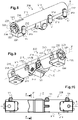
- the pivoting system 100; 200 comprises, inside a housing 110, 210, a rotary drive shaft 120, 165; 220, 265, a damper 140; 240, a constrained torsion spring 180 connected to the rotating drive shaft and a device for adjusting the initial torsional stress of the torsion spring, which comprises a toothed wheel 150; 250 linked to the torsion spring 180 as well as an adjustment screw 170; 270 whose threaded body cooperates with the notching of the toothed wheel so that the screwing / unscrewing of the adjusting screw 170; 270 causes rotation of the toothed wheel 150; 250 around its axis.
- the adjustment screw 170; 270 is a worm.
- the pivoting system could comprise two torsion springs associated with two shock absorbers as is the case in the pivoting system described in the documents FR3103642 and EP3829015 .
- the housing 110; 210 has a generally cylindrical shape elongated along an axis X. It has at the ends two circular openings 111A; 211A. It is formed of two shells 111; 211 generally semi-cylindrical, positioned edge to edge and secured to each other along their longitudinal edges 111B, 111C; 211B,211C.
- the means for securing the two shells 111; 211 comprise a click system and a screw system.
- the snap system comprises along a longitudinal edge 111C; 211C of one of the hulls 111; 211 teeth 114; 214 and along the longitudinal edge 111C; 211C corresponding to the other shell 111; 211 of windows 115; 215 in which snap the teeth 114; 214.
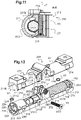
- the screwing system comprises along the other two corresponding longitudinal edges 111B; 211B of the two shells 111; 211 threaded chimneys 112; 212 in which screws V1 are screwed (see figures 1, 2 , 5, 6 , 8, 9 , 12 , 13 and 14 ).
- the housing 110; 210 houses said adjustment device.
- it comprises a housing 116; 216 of suitable shape which accommodates the toothed wheel 150; 250 cooperating with the thread of the adjustment screw 170; 270 including the end 171; 271 is engaged in an internal notch 117A; 217A of the case 110; 210 and whose operating head 172; 272 is engaged in a circular opening 117B; 217B of a side face of the housing 110; 210, through which it is accessible to an installer (see figure 2 , 5 , 6 , 7 , 9 , 12 to 15 ).
- the axis X2 is the axis of rotation of the toothed wheel 150; 250.
- the adjustment screw 170 extends along an axis Z perpendicular to the axis X, it rotates around the axis Z by cooperating with the teeth or the notching of the cogwheel 150;250.
- each cylindrical stud 151 is split with an axial slot 152 which opens out at the free end 153 of the cylindrical stud 151 (see figure 7 ).
- the toothed wheel 150 and the two cylindrical studs 151 belong to a single one-piece metal part.
- the pivoting system 200 is provided on one side of the toothed wheel 250 (located on the left on the figures 12 to 15 ), along the axis X2, a first additional stud 251B which extends from said cylindrical stud 251 and whose outer surface has a hexagonal profile as well as a cylindrical end stud 252B which extends from the stud additional 251B. It is also provided on the other side of the toothed wheel 250 (located on the right on the figures 12 to 15 ), a guide pin 251A which extends along axis X2 from said cylindrical stud 251.
- This guide pin 251A is a cylinder split axially by a slot 252A which opens at the free end 253 of said cylinder so that she separates it into two half-cylinders 251A.
- the cylindrical studs 251, the additional stud 251B with the hexagonal profile, the end cylindrical stud 252B and the guide shaft 251A have as common axis the X axis of the housing 210.
- the toothed wheel 250, the cylindrical studs 251, the additional stud 251B with the hexagonal profile, the end cylindrical stud 252B and the guide pin 251A belong to a single one-piece metal part.
- two semi-cylindrical cradles 202 are advantageously provided in the two shells 211 which surround the cylindrical end stud 252B so as to center the toothed wheel 250 on the axis of rotation X.
- the two studs 251 linked directly to the toothed wheel 250 and the cylindrical end stud 252B linked indirectly to the toothed wheel 250 are surrounded by cylindrical surfaces 216A, 202 of the housing 210, centered on the axis X of the housing 210, to ensure the centering of the toothed wheel 250 on said axis X of the housing 210.
- pivoting system 100; 200 there is provided inside the housing 110; 210, on either side of the toothed wheel 150; 250, a rotary drive system.
- This rotary drive system comprises on one side of the toothed wheel 150; 250 (located on the left on the figures 5 to 7 and 12 to 15 ), a first part 120; 220 of the rotary drive shaft and, on the other side of the toothed wheel 150; 250 (located on the right on the figures 5 to 7 and 12 to 15 ), a second part 165; 265 of the rotary drive shaft.
- the two parts 120, 165; 220.265 of the rotary drive shaft are aligned along an axis X1 coinciding with the axis X2 of said cylindrical studs 151; 251.
- first and second parts 120, 165; 220,265 of the rotary drive shaft are different but they could be identical as is the case in the pivoting system described in the documents FR3103642 and EP3829015 .
- Each of the first and second parts 120.165; 220.265 of the rotary drive shaft is a one-piece metal part.
- the first part 120; 220 of the rotary drive shaft has one end provided with a slot 121; 221 and one end provided with a disk 122; 222 which closes a circular opening 111A; 211A at the end of the housing. 110;210.
- the outer face 123;223 of the disc 122;222 that is to say the face of the disc 122;222 facing the outside of the housing 110;210 when the disc 122;222 closes the circular opening 111A;211A end of the housing 110; 210, carries two projecting studs 124; 224 placed diametrically opposite with respect to the center of the disc 122; 222.
- annular flange 130 is positioned on this first part 120 of the rotary drive shaft, close to the disc 122 end.
- This annular collar 130 comprises in its circular outer edge, two notches 135 placed diametrically opposite with respect to the center of the collar.
- the end disc 222 of the first part 220 of the drive shaft has two openings 226 positioned diametrically opposite with respect to the center of the disc 222.
- the first part 120; 220 of the rotary drive shaft comprises a threaded duct 125; 225 which opens at the center of the outer face 123; 223 of the disc 122; 222.
- the rotation drive system comprises a damper 140; 240 linked to the first part 120; 220 of the rotation drive shaft.
- the 140;240 shock is quite classic. It comprises an outer cylinder 141; 241 and an inner cylinder 144 concentric around the X axis as well as a viscous material provided between the two cylinders.
- the outer cylinder 141; 241 carries on its outer face a rib 142; 242 extending along a generatrix of the outer cylinder 141; 241 (see figures 5 to 7 and figure 13 and 14 ).
- This rib 142;242 is received in a window 118;218 provided in the wall of one of the shells 111;211 of the housing 110;210 so that the outer cylinder 141;241 of the damper 140;240 is fixed in the housing 110; 210.
- the inner cylinder 144 of the damper 140; 240 is able to rotate in the outer cylinder 141; 241, by rubbing on the viscous material.
- Each end of the internal cylinder 144 is equipped with an annular disc 143; 243 which closes the cylindrical internal space provided between the external 141; 241 and internal 144 cylinders, filled with the viscous material.
- annular disc 143; 243 (the one located on the side of the disc 122; 222 end of the first part 120; 220 of the rotary drive shaft) carries two studs 145 placed diametrically opposite with respect to the center of the annular disc 143; 243 .
- the first part 120; 220 of the rotary drive shaft is threaded through the inner cylinder 144 of the damper 140; 240 so that the disc 122; 222 closes the circular opening 111A; 211A end of the housing 110; 210 and the split end 121; 221 emerges outside the damper 140; 240, opposite and at a distance from the end of the stud cylindrical 151; 252B linked directly or indirectly to the toothed wheel 150; 250.
- the assembly formed by the first part 120; 220 of the rotary drive shaft and the damper 140; 240 to which it is linked, is separated from the toothed wheel 150; in the sense that no element is provided to establish any mechanical connection between this assembly and the toothed wheel 150; 250.
- a torsion spring is connected, on the one hand, to the split end of the first part of the drive shaft, and, on the other hand, to the corresponding cylindrical stud connected to said toothed wheel.
- the second part 165; 265 of the rotational drive shaft is a cylindrical pin of axis X1 which has an upper section and a shorter length compared to the section and the length of the first part 120; 220 .
- the section of the cylindrical journal is here practically identical to the section of the cylindrical studs 151; 251 linked to the toothed wheel 150; 250.
- the second part 165; 265 of the rotary drive shaft comprises, at one of its ends, a first disc 163; 263 which closes the other circular opening 111A; 211A at the end of the housing 110; 210.
- This second part 165; 265 comprises, at its other end, a second disc 162; 262 of identical diameter to the diameter of the first disc 163; 263.
- a guide pin 160; 260 which extends along the axis X1 from the second disc 162; 262.
- This guide pin 160; 260 is a cylinder split axially by a slot 160A; 260A which opens out at the end 161; 261 of said cylinder so that it separates it into two half-cylinders 160B; 260B.
- the length of the guide pin 160 connected to the second part 165 of the rotation drive shaft according to the first embodiment of the pivoting system 100 is significantly greater than the length of the guide pin 260 connected to the second part 265 of the rotation drive shaft according to the second embodiment of the pivoting system 200 (see the figures 14 and 15 ).
- the guide pin 160 which extends along the X axis, fills the space between the second disc 162 and the split end 152 of the cylindrical stud 151 connected to said toothed wheel 150.
- the end 153 said cylindrical stud 151 faces the end 161 of said guide pin 160.
- the length of the guide pin 251A connected to the toothed wheel 250 is identical or practically identical to the length of the guide pin 260 connected to the second part 265 of the drive shaft. spinning drive.
- the guide pin 260 extends along the X axis in the extension of the guide pin 251A connected to the toothed wheel 250 so that the two aligned guide pins 251A; 260 fill the space between the second disc 262 of the second part 265 of the drive shaft in rotation and the cylindrical stud 251 connected to said toothed wheel 250.
- the free end 253 of the guide pin 251A connected to the toothed wheel 250 faces at the free end 261 of the guide pin 260 connected to the second part 265 of the rotary drive shaft.
- each shell 211 of the housing 210 there is provided on the inner face 211E of each shell 211 of the housing 210 a rib 201 capable of being placed against a face 262B of the second disc 262 facing the corresponding face 263B of the first disc 263 of the second part 265 of the drive shaft in rotation.
- This Rib 201 forms a stop which limits any displacements in translation along the axis X of the second part 265 of the drive shaft.
- the second part 165; 265 of the rotation drive shaft comprises a threaded duct (not visible in the figures) which opens out at the center of the outer face 163A; 263A of the first disc 163; 263.
- the rotation drive system includes a torsion spring 180.
- substantially the entire length of the torsion spring 180 is wound around the guide pin 160 attached to the second part 165 of the rotary drive shaft.
- the torsion spring 180 has, on the one hand, one end engaged in the slot 152 of a cylindrical stud 151 connected to the toothed wheel 150 so as to be connected to this toothed wheel 150, and, on the other hand, a other end engaged in the slot 160A of the guide pin 160 so as to be connected to said second part 165 of the drive shaft in rotation.
- the torsion spring 180 is wound around the two guide axes 251A, 260 aligned, that attached to the toothed wheel 250 and that attached to the second part 265 of the rotary drive shaft.
- a first end of the torsion spring 180 is engaged in the slot 252A of the guide pin 251A so as to be linked to the toothed wheel 250 and the other end of the torsion spring 180 is engaged in the slot 260A of the guide pin 260 so as to be linked to said second part 265 of the rotary drive shaft.
- torsion spring 180 of the pivoting system 100; 200 To adjust the torsional stress of the torsion spring 180 of the pivoting system 100; 200, simply screw or unscrew the adjustment screw 170; 270 using a screwdriver whose tip is engaged in the slot of the operating head 172; 272 of said adjustment screw 170; 270, so as to turn the toothed wheel 150; 250 in the appropriate direction.
- the toothed wheel 150; 250 drives the corresponding cylindrical pin 151; torsion spring 180.
- Adjusting the stress of the torsion spring 180 makes it possible to adjust the pivoting torque of the second part 165; 265 of the rotation drive shaft and therefore of the rotation drive shaft itself.
- This pivoting torque is dampened by the shock absorber 140;240.
- the locking element is advantageously a locking screw V2; V3.
- the housing 110; 210 housing the rotary drive shaft, the damper 140; 240, the torsion spring 180 and said device for adjusting the initial torsional stress of the torsion spring, is pierced with a through conduit 119; 219 which establishes communication between the inside and the outside of said housing 110; 210, and through which is engaged from the outside said locking element V2; V3 to access the interior of said box 110; 210.
- the through conduit 119; 219 is a threaded conduit in which the locking screw V2; V3 is screwed (see the figure 4 and 11 ).
- the through conduit 119; 219 extends through one of the two shells 111; 211 along a longitudinal axis Y; Z1 transverse to the longitudinal axis X of said housing 110; 210.
- the longitudinal axis Y of the through conduit 119 is a vertical axis with respect to the position of use of the housing 110 represented on the figure 1 .
- said through-duct 119 passes through the thickness of the wall of shell 111 and opens inside housing 110 in line with a notch 150A of the notching of said toothed wheel 150 (see figure 4 ).
- the locking screw V2 is screwed through the through conduit 119, using a screwdriver whose tip is introduced into the imprint of the locking screw V2, so that the end tip VE2 of the locking screw V2 is engaged in the said notch 150A of the said toothed wheel 150 and blocks the rotation of the said wheel toothed 150.
- the longitudinal axis Z1 of the through conduit 219 is a horizontal axis, parallel to the axis Z around which the adjustment screw 270 is driven in rotation, relative to the position of use of the housing 210 represented on the figure 9 .
- said through conduit 219 emerges inside the housing 210 in an offset manner with respect to said toothed wheel 250, in line with a stud integral with said toothed wheel 250.
- the stud in question here is the additional stud 251B with hexagonal profile.
- the through conduit 219 has an inlet which passes through the thickness of a side part of the wall of the corresponding shell 211 of the box 210 and which accommodates the head of the locking screw V3.
- the through conduit 219 has an outlet which passes through the thickness of another side portion of the wall of the shell 111 of the housing 210 (see figure 15 ). Between the inlet and the outlet the through conduit 219 opens into said box 210.
- the locking screw V3 is screwed through the through conduit 219 so that a part of the thread of its threaded body VC3 hooks the hexagonal outer surface of the additional stud 251B secured to said toothed wheel 250 and blocks the rotation of said toothed wheel 250.
- the closed box 110; 210 housing all the elements described above, is screwed to the rear of the frame of the front plate.
- the rotation drive shaft of the swivel system 100; 200 is linked to connecting rods which cooperate in a sliding manner with said device support.
- the connecting rods comprise for this purpose a central orifice and several peripheral orifices arranged in a circle around the central orifice.
- the nipples 124.164; 224.264 of the discs 122.163; 222.263 end of the two parts of the rotary drive shaft are engaged in two peripheral holes of the connecting rods.
- a screw is engaged through the central hole of each connecting rod and is screwed into the threaded conduit 125; 225 of the corresponding part of the rotation drive shaft. In this way, the connecting rods are solidly secured to the two discs 122.163; 222.263 end of the rotating drive shaft.
- the apparatus locking system comprises in known manner either, on the one hand, at least one locking arm movable between a locking position in which a locking part of said locking arm lock bears against a blocking surface of the device support and a release position in which said blocking part is spaced from said blocking surface, and, on the other hand, an actuating button for controlling the movement of each locking arm.
- elastic means for recalling the locking arm to its locking position.
- the apparatus support In the closed state of the apparatus, the apparatus support is held in the lowered position under the front plate by the locking arm.
- the torsion spring 180 of the pivoting system 100; 200 then releases its torsional energy and causes the rotational drive shaft 120.165 to pivot; 220,265. This pivots the two connecting rods which slide against the device support and drive the device support in rotation, which pivots until it reaches its raised position above the front plate, therefore above the receiving wall.
- the device carrier reaches its stable raised position when its stop element comes into abutment at the bottom of the stop groove of the facade plate.
Landscapes
- Engineering & Computer Science (AREA)
- General Engineering & Computer Science (AREA)
- Mechanical Engineering (AREA)
- Pivots And Pivotal Connections (AREA)
- Vibration Prevention Devices (AREA)
- Closing And Opening Devices For Wings, And Checks For Wings (AREA)
Applications Claiming Priority (1)
| Application Number | Priority Date | Filing Date | Title |
|---|---|---|---|
| CN202120441780.9U CN214754256U (zh) | 2021-03-01 | 2021-03-01 | 弹开式插座用阻尼装置 |
Publications (3)
| Publication Number | Publication Date |
|---|---|
| EP4053369A1 true EP4053369A1 (de) | 2022-09-07 |
| EP4053369B1 EP4053369B1 (de) | 2024-03-13 |
| EP4053369C0 EP4053369C0 (de) | 2024-03-13 |
Family
ID=78590620
Family Applications (1)
| Application Number | Title | Priority Date | Filing Date |
|---|---|---|---|
| EP22158269.5A Active EP4053369B1 (de) | 2021-03-01 | 2022-02-23 | Schwenksystem für einen geräteträger und einbaugerät mit einem solchen schwenksystem |
Country Status (3)
| Country | Link |
|---|---|
| EP (1) | EP4053369B1 (de) |
| CN (1) | CN214754256U (de) |
| ES (1) | ES2978945T3 (de) |
Citations (4)
| Publication number | Priority date | Publication date | Assignee | Title |
|---|---|---|---|---|
| CN203850477U (zh) * | 2014-04-30 | 2014-09-24 | 温州西诺电工科技有限公司 | 一种地面插座的可调阻尼装置 |
| US20150218864A1 (en) * | 2014-02-05 | 2015-08-06 | Zero Zone, Inc. | Door closer mechanism for display case |
| US20200291681A1 (en) * | 2019-03-12 | 2020-09-17 | Ford Global Technologies, Llc | Locking mechanism for a motor |
| FR3103642A1 (fr) | 2019-11-26 | 2021-05-28 | Legrand France | Appareillage à support d’appareillage basculant |
-
2021
- 2021-03-01 CN CN202120441780.9U patent/CN214754256U/zh active Active
-
2022
- 2022-02-23 ES ES22158269T patent/ES2978945T3/es active Active
- 2022-02-23 EP EP22158269.5A patent/EP4053369B1/de active Active
Patent Citations (5)
| Publication number | Priority date | Publication date | Assignee | Title |
|---|---|---|---|---|
| US20150218864A1 (en) * | 2014-02-05 | 2015-08-06 | Zero Zone, Inc. | Door closer mechanism for display case |
| CN203850477U (zh) * | 2014-04-30 | 2014-09-24 | 温州西诺电工科技有限公司 | 一种地面插座的可调阻尼装置 |
| US20200291681A1 (en) * | 2019-03-12 | 2020-09-17 | Ford Global Technologies, Llc | Locking mechanism for a motor |
| FR3103642A1 (fr) | 2019-11-26 | 2021-05-28 | Legrand France | Appareillage à support d’appareillage basculant |
| EP3829015A1 (de) | 2019-11-26 | 2021-06-02 | Legrand France | Gerät mit halterung für schwenkbares gerät |
Also Published As
| Publication number | Publication date |
|---|---|
| EP4053369B1 (de) | 2024-03-13 |
| EP4053369C0 (de) | 2024-03-13 |
| ES2978945T3 (es) | 2024-09-23 |
| CN214754256U (zh) | 2021-11-16 |
Similar Documents
| Publication | Publication Date | Title |
|---|---|---|
| FR2728451A1 (fr) | Dispositif amortisseur rotatif pour couvercle pivotant, avec mecanisme a autoblocage en position verticale | |
| FR2747423A1 (fr) | Dispositif de roulement pour ouvrant coulissant de porte, fenetre ou analogue | |
| WO1996035890A1 (fr) | Appareil d'accouplement hydrocinetique, notamment pour vehicule automobile | |
| EP1087075B1 (de) | Permanente Verankerungsvorrichtung | |
| EP0935324B1 (de) | Eckpfosten für Schaltschrank und damit ausgerüsteter Schaltschrank | |
| EP3829015B1 (de) | Gerät mit halterung für schwenkbares gerät | |
| EP4053369B1 (de) | Schwenksystem für einen geräteträger und einbaugerät mit einem solchen schwenksystem | |
| FR2726456A1 (fr) | Dispositif de blocage d'une cuve sur un support moteur pour appareil de preparation des aliments | |
| EP2927536B1 (de) | Lineares stellglied und entsprechende abdeckvorrichtung | |
| EP0551234B1 (de) | Gerät, wie zum Beispiel elektrisches Haus- und Küchengerät, mit einer mit waagerechter Drehachse ausgestattener Tür und eine Ausgleichsvorrichtung der Türgewichtes zur Ausstattung mit einer Verkleidungsplatte bestimmt | |
| EP2516778B1 (de) | Absperrvorrichtung und entsprechende baugruppe | |
| FR2652374A1 (fr) | Poignee pour portiere de vehicule a moteur. | |
| EP3829014B1 (de) | Gerät mit einer kippbaren gerätehalterung und einem verriegelungssystem, das mittels eines kippbaren betätigungsknopfes entriegelt werden kann | |
| FR2907080A1 (fr) | Dispositif de fixation d'un bras d'essuie-glace de vehicule automobile | |
| FR3100089A1 (fr) | Dispositif de montage d’un boîtier multi-appareillage, cadre de montage comprenant un tel dispositif de montage et dispositif multi-appareillage comprenant un tel cadre de montage et un boîtier multi-appareillage | |
| EP1059409A1 (de) | Antriebsgetriebe für Schlossnuss | |
| FR3096714A3 (fr) | Charnière de type à peigne pour fenêtre et portes à vantail pivotant | |
| FR2799805A1 (fr) | Dispositif d'ancrage dit permanent | |
| EP2632002B1 (de) | Dichtes elektrisches Gerät mit Pufferelement | |
| FR2730264A1 (fr) | Ensemble de plaques et poignees de porte comportant un dispositif de rappel en position de la poignee | |
| FR2780208A1 (fr) | Coffret a ouverture et equipe d'une piece de liaison mecanique pour la fixation de son dispositif d'obturation | |
| FR2658236A1 (fr) | Ensemble pour la realisation d'un chassis de survitrage. | |
| EP0119361B1 (de) | Einfassungsprofil für ein schwenkbares Verbundfenster | |
| EP1472427B1 (de) | Scharnieranordnung zur befestigung eines beweglichen hebefensters an einer festgelegten konstruktion | |
| FR2766858A1 (fr) | Dispositif de rappel a ressort pour poignees de portes ou de fenetres |
Legal Events
| Date | Code | Title | Description |
|---|---|---|---|
| PUAI | Public reference made under article 153(3) epc to a published international application that has entered the european phase |
Free format text: ORIGINAL CODE: 0009012 |
|
| STAA | Information on the status of an ep patent application or granted ep patent |
Free format text: STATUS: THE APPLICATION HAS BEEN PUBLISHED |
|
| AK | Designated contracting states |
Kind code of ref document: A1 Designated state(s): AL AT BE BG CH CY CZ DE DK EE ES FI FR GB GR HR HU IE IS IT LI LT LU LV MC MK MT NL NO PL PT RO RS SE SI SK SM TR |
|
| STAA | Information on the status of an ep patent application or granted ep patent |
Free format text: STATUS: REQUEST FOR EXAMINATION WAS MADE |
|
| 17P | Request for examination filed |
Effective date: 20220905 |
|
| RBV | Designated contracting states (corrected) |
Designated state(s): AL AT BE BG CH CY CZ DE DK EE ES FI FR GB GR HR HU IE IS IT LI LT LU LV MC MK MT NL NO PL PT RO RS SE SI SK SM TR |
|
| GRAP | Despatch of communication of intention to grant a patent |
Free format text: ORIGINAL CODE: EPIDOSNIGR1 |
|
| STAA | Information on the status of an ep patent application or granted ep patent |
Free format text: STATUS: GRANT OF PATENT IS INTENDED |
|
| RIC1 | Information provided on ipc code assigned before grant |
Ipc: F16H 57/039 20120101ALI20230928BHEP Ipc: F16H 19/00 20060101ALI20230928BHEP Ipc: F16H 1/16 20060101ALI20230928BHEP Ipc: E05F 1/12 20060101ALI20230928BHEP Ipc: E05F 1/10 20060101ALI20230928BHEP Ipc: E05F 3/22 20060101ALI20230928BHEP Ipc: E05F 3/14 20060101AFI20230928BHEP |
|
| INTG | Intention to grant announced |
Effective date: 20231025 |
|
| GRAS | Grant fee paid |
Free format text: ORIGINAL CODE: EPIDOSNIGR3 |
|
| GRAA | (expected) grant |
Free format text: ORIGINAL CODE: 0009210 |
|
| STAA | Information on the status of an ep patent application or granted ep patent |
Free format text: STATUS: THE PATENT HAS BEEN GRANTED |
|
| AK | Designated contracting states |
Kind code of ref document: B1 Designated state(s): AL AT BE BG CH CY CZ DE DK EE ES FI FR GB GR HR HU IE IS IT LI LT LU LV MC MK MT NL NO PL PT RO RS SE SI SK SM TR |
|
| REG | Reference to a national code |
Ref country code: GB Ref legal event code: FG4D Free format text: NOT ENGLISH |
|
| REG | Reference to a national code |
Ref country code: CH Ref legal event code: EP |
|
| REG | Reference to a national code |
Ref country code: DE Ref legal event code: R096 Ref document number: 602022002300 Country of ref document: DE |
|
| REG | Reference to a national code |
Ref country code: IE Ref legal event code: FG4D Free format text: LANGUAGE OF EP DOCUMENT: FRENCH |
|
| U01 | Request for unitary effect filed |
Effective date: 20240318 |
|
| U07 | Unitary effect registered |
Designated state(s): AT BE BG DE DK EE FI FR IT LT LU LV MT NL PT SE SI Effective date: 20240325 |
|
| PG25 | Lapsed in a contracting state [announced via postgrant information from national office to epo] |
Ref country code: GR Free format text: LAPSE BECAUSE OF FAILURE TO SUBMIT A TRANSLATION OF THE DESCRIPTION OR TO PAY THE FEE WITHIN THE PRESCRIBED TIME-LIMIT Effective date: 20240614 |
|
| PG25 | Lapsed in a contracting state [announced via postgrant information from national office to epo] |
Ref country code: HR Free format text: LAPSE BECAUSE OF FAILURE TO SUBMIT A TRANSLATION OF THE DESCRIPTION OR TO PAY THE FEE WITHIN THE PRESCRIBED TIME-LIMIT Effective date: 20240313 Ref country code: RS Free format text: LAPSE BECAUSE OF FAILURE TO SUBMIT A TRANSLATION OF THE DESCRIPTION OR TO PAY THE FEE WITHIN THE PRESCRIBED TIME-LIMIT Effective date: 20240613 |
|
| PG25 | Lapsed in a contracting state [announced via postgrant information from national office to epo] |
Ref country code: RS Free format text: LAPSE BECAUSE OF FAILURE TO SUBMIT A TRANSLATION OF THE DESCRIPTION OR TO PAY THE FEE WITHIN THE PRESCRIBED TIME-LIMIT Effective date: 20240613 Ref country code: NO Free format text: LAPSE BECAUSE OF FAILURE TO SUBMIT A TRANSLATION OF THE DESCRIPTION OR TO PAY THE FEE WITHIN THE PRESCRIBED TIME-LIMIT Effective date: 20240613 Ref country code: HR Free format text: LAPSE BECAUSE OF FAILURE TO SUBMIT A TRANSLATION OF THE DESCRIPTION OR TO PAY THE FEE WITHIN THE PRESCRIBED TIME-LIMIT Effective date: 20240313 Ref country code: GR Free format text: LAPSE BECAUSE OF FAILURE TO SUBMIT A TRANSLATION OF THE DESCRIPTION OR TO PAY THE FEE WITHIN THE PRESCRIBED TIME-LIMIT Effective date: 20240614 |
|
| REG | Reference to a national code |
Ref country code: ES Ref legal event code: FG2A Ref document number: 2978945 Country of ref document: ES Kind code of ref document: T3 Effective date: 20240923 |
|
| PG25 | Lapsed in a contracting state [announced via postgrant information from national office to epo] |
Ref country code: IS Free format text: LAPSE BECAUSE OF FAILURE TO SUBMIT A TRANSLATION OF THE DESCRIPTION OR TO PAY THE FEE WITHIN THE PRESCRIBED TIME-LIMIT Effective date: 20240713 |
|
| PG25 | Lapsed in a contracting state [announced via postgrant information from national office to epo] |
Ref country code: SM Free format text: LAPSE BECAUSE OF FAILURE TO SUBMIT A TRANSLATION OF THE DESCRIPTION OR TO PAY THE FEE WITHIN THE PRESCRIBED TIME-LIMIT Effective date: 20240313 |
|
| PG25 | Lapsed in a contracting state [announced via postgrant information from national office to epo] |
Ref country code: CZ Free format text: LAPSE BECAUSE OF FAILURE TO SUBMIT A TRANSLATION OF THE DESCRIPTION OR TO PAY THE FEE WITHIN THE PRESCRIBED TIME-LIMIT Effective date: 20240313 |
|
| PG25 | Lapsed in a contracting state [announced via postgrant information from national office to epo] |
Ref country code: PL Free format text: LAPSE BECAUSE OF FAILURE TO SUBMIT A TRANSLATION OF THE DESCRIPTION OR TO PAY THE FEE WITHIN THE PRESCRIBED TIME-LIMIT Effective date: 20240313 |
|
| PG25 | Lapsed in a contracting state [announced via postgrant information from national office to epo] |
Ref country code: SK Free format text: LAPSE BECAUSE OF FAILURE TO SUBMIT A TRANSLATION OF THE DESCRIPTION OR TO PAY THE FEE WITHIN THE PRESCRIBED TIME-LIMIT Effective date: 20240313 |
|
| PG25 | Lapsed in a contracting state [announced via postgrant information from national office to epo] |
Ref country code: SM Free format text: LAPSE BECAUSE OF FAILURE TO SUBMIT A TRANSLATION OF THE DESCRIPTION OR TO PAY THE FEE WITHIN THE PRESCRIBED TIME-LIMIT Effective date: 20240313 Ref country code: SK Free format text: LAPSE BECAUSE OF FAILURE TO SUBMIT A TRANSLATION OF THE DESCRIPTION OR TO PAY THE FEE WITHIN THE PRESCRIBED TIME-LIMIT Effective date: 20240313 Ref country code: RO Free format text: LAPSE BECAUSE OF FAILURE TO SUBMIT A TRANSLATION OF THE DESCRIPTION OR TO PAY THE FEE WITHIN THE PRESCRIBED TIME-LIMIT Effective date: 20240313 Ref country code: PL Free format text: LAPSE BECAUSE OF FAILURE TO SUBMIT A TRANSLATION OF THE DESCRIPTION OR TO PAY THE FEE WITHIN THE PRESCRIBED TIME-LIMIT Effective date: 20240313 Ref country code: IS Free format text: LAPSE BECAUSE OF FAILURE TO SUBMIT A TRANSLATION OF THE DESCRIPTION OR TO PAY THE FEE WITHIN THE PRESCRIBED TIME-LIMIT Effective date: 20240713 Ref country code: CZ Free format text: LAPSE BECAUSE OF FAILURE TO SUBMIT A TRANSLATION OF THE DESCRIPTION OR TO PAY THE FEE WITHIN THE PRESCRIBED TIME-LIMIT Effective date: 20240313 |
|
| REG | Reference to a national code |
Ref country code: DE Ref legal event code: R097 Ref document number: 602022002300 Country of ref document: DE |
|
| PLBE | No opposition filed within time limit |
Free format text: ORIGINAL CODE: 0009261 |
|
| STAA | Information on the status of an ep patent application or granted ep patent |
Free format text: STATUS: NO OPPOSITION FILED WITHIN TIME LIMIT |
|
| 26N | No opposition filed |
Effective date: 20241216 |
|
| U20 | Renewal fee for the european patent with unitary effect paid |
Year of fee payment: 4 Effective date: 20250205 |
|
| PG25 | Lapsed in a contracting state [announced via postgrant information from national office to epo] |
Ref country code: MC Free format text: LAPSE BECAUSE OF FAILURE TO SUBMIT A TRANSLATION OF THE DESCRIPTION OR TO PAY THE FEE WITHIN THE PRESCRIBED TIME-LIMIT Effective date: 20240313 |
|
| REG | Reference to a national code |
Ref country code: CH Ref legal event code: PL |
|
| PG25 | Lapsed in a contracting state [announced via postgrant information from national office to epo] |
Ref country code: CH Free format text: LAPSE BECAUSE OF NON-PAYMENT OF DUE FEES Effective date: 20250228 |
|
| PG25 | Lapsed in a contracting state [announced via postgrant information from national office to epo] |
Ref country code: IE Free format text: LAPSE BECAUSE OF NON-PAYMENT OF DUE FEES Effective date: 20250223 |
|
| U20 | Renewal fee for the european patent with unitary effect paid |
Year of fee payment: 5 Effective date: 20260121 |
|
| PGFP | Annual fee paid to national office [announced via postgrant information from national office to epo] |
Ref country code: GB Payment date: 20260121 Year of fee payment: 5 |
|
| PGFP | Annual fee paid to national office [announced via postgrant information from national office to epo] |
Ref country code: ES Payment date: 20260302 Year of fee payment: 5 |