EP4053388A1 - Turboladeranordnung und verfahren zum steuern des betriebs einer turboladeranordnung - Google Patents
Turboladeranordnung und verfahren zum steuern des betriebs einer turboladeranordnung Download PDFInfo
- Publication number
- EP4053388A1 EP4053388A1 EP21160717.1A EP21160717A EP4053388A1 EP 4053388 A1 EP4053388 A1 EP 4053388A1 EP 21160717 A EP21160717 A EP 21160717A EP 4053388 A1 EP4053388 A1 EP 4053388A1
- Authority
- EP
- European Patent Office
- Prior art keywords
- power converter
- compressor
- turbocharging assembly
- turbine
- housing
- Prior art date
- Legal status (The legal status is an assumption and is not a legal conclusion. Google has not performed a legal analysis and makes no representation as to the accuracy of the status listed.)
- Withdrawn
Links
Images
Classifications
-
- F—MECHANICAL ENGINEERING; LIGHTING; HEATING; WEAPONS; BLASTING
- F02—COMBUSTION ENGINES; HOT-GAS OR COMBUSTION-PRODUCT ENGINE PLANTS
- F02B—INTERNAL-COMBUSTION PISTON ENGINES; COMBUSTION ENGINES IN GENERAL
- F02B37/00—Engines characterised by provision of pumps driven at least for part of the time by exhaust
- F02B37/04—Engines with exhaust drive and other drive of pumps, e.g. with exhaust-driven pump and mechanically-driven second pump
- F02B37/10—Engines with exhaust drive and other drive of pumps, e.g. with exhaust-driven pump and mechanically-driven second pump at least one pump being alternatively or simultaneously driven by exhaust and other drive, e.g. by pressurised fluid from a reservoir or an engine-driven pump
-
- F—MECHANICAL ENGINEERING; LIGHTING; HEATING; WEAPONS; BLASTING
- F02—COMBUSTION ENGINES; HOT-GAS OR COMBUSTION-PRODUCT ENGINE PLANTS
- F02B—INTERNAL-COMBUSTION PISTON ENGINES; COMBUSTION ENGINES IN GENERAL
- F02B39/00—Component parts, details, or accessories relating to, driven charging or scavenging pumps, not provided for in groups F02B33/00 - F02B37/00
- F02B39/005—Cooling of pump drives
-
- F—MECHANICAL ENGINEERING; LIGHTING; HEATING; WEAPONS; BLASTING
- F02—COMBUSTION ENGINES; HOT-GAS OR COMBUSTION-PRODUCT ENGINE PLANTS
- F02B—INTERNAL-COMBUSTION PISTON ENGINES; COMBUSTION ENGINES IN GENERAL
- F02B39/00—Component parts, details, or accessories relating to, driven charging or scavenging pumps, not provided for in groups F02B33/00 - F02B37/00
- F02B39/02—Drives of pumps; Varying pump drive gear ratio
- F02B39/08—Non-mechanical drives, e.g. fluid drives having variable gear ratio
- F02B39/10—Non-mechanical drives, e.g. fluid drives having variable gear ratio electric
-
- F—MECHANICAL ENGINEERING; LIGHTING; HEATING; WEAPONS; BLASTING
- F02—COMBUSTION ENGINES; HOT-GAS OR COMBUSTION-PRODUCT ENGINE PLANTS
- F02C—GAS-TURBINE PLANTS; AIR INTAKES FOR JET-PROPULSION PLANTS; CONTROLLING FUEL SUPPLY IN AIR-BREATHING JET-PROPULSION PLANTS
- F02C6/00—Plural gas-turbine plants; Combinations of gas-turbine plants with other apparatus; Adaptations of gas-turbine plants for special use
- F02C6/04—Gas-turbine plants providing heated or pressurised working fluid for other apparatus, e.g. without mechanical power output
- F02C6/10—Gas-turbine plants providing heated or pressurised working fluid for other apparatus, e.g. without mechanical power output supplying working fluid to a user, e.g. a chemical process, which returns working fluid to a turbine of the plant
- F02C6/12—Turbochargers, i.e. plants for augmenting mechanical power output of internal-combustion piston engines by increase of charge pressure
-
- F—MECHANICAL ENGINEERING; LIGHTING; HEATING; WEAPONS; BLASTING
- F02—COMBUSTION ENGINES; HOT-GAS OR COMBUSTION-PRODUCT ENGINE PLANTS
- F02M—SUPPLYING COMBUSTION ENGINES IN GENERAL WITH COMBUSTIBLE MIXTURES OR CONSTITUENTS THEREOF
- F02M35/00—Combustion-air cleaners, air intakes, intake silencers, or induction systems specially adapted for, or arranged on, internal-combustion engines
- F02M35/10—Air intakes; Induction systems
- F02M35/1015—Air intakes; Induction systems characterised by the engine type
- F02M35/10157—Supercharged engines
-
- F—MECHANICAL ENGINEERING; LIGHTING; HEATING; WEAPONS; BLASTING
- F02—COMBUSTION ENGINES; HOT-GAS OR COMBUSTION-PRODUCT ENGINE PLANTS
- F02M—SUPPLYING COMBUSTION ENGINES IN GENERAL WITH COMBUSTIBLE MIXTURES OR CONSTITUENTS THEREOF
- F02M35/00—Combustion-air cleaners, air intakes, intake silencers, or induction systems specially adapted for, or arranged on, internal-combustion engines
- F02M35/10—Air intakes; Induction systems
- F02M35/10242—Devices or means connected to or integrated into air intakes; Air intakes combined with other engine or vehicle parts
-
- F—MECHANICAL ENGINEERING; LIGHTING; HEATING; WEAPONS; BLASTING
- F02—COMBUSTION ENGINES; HOT-GAS OR COMBUSTION-PRODUCT ENGINE PLANTS
- F02M—SUPPLYING COMBUSTION ENGINES IN GENERAL WITH COMBUSTIBLE MIXTURES OR CONSTITUENTS THEREOF
- F02M35/00—Combustion-air cleaners, air intakes, intake silencers, or induction systems specially adapted for, or arranged on, internal-combustion engines
- F02M35/12—Intake silencers ; Sound modulation, transmission or amplification
- F02M35/1288—Intake silencers ; Sound modulation, transmission or amplification combined with or integrated into other devices ; Plurality of air intake silencers
-
- F—MECHANICAL ENGINEERING; LIGHTING; HEATING; WEAPONS; BLASTING
- F02—COMBUSTION ENGINES; HOT-GAS OR COMBUSTION-PRODUCT ENGINE PLANTS
- F02M—SUPPLYING COMBUSTION ENGINES IN GENERAL WITH COMBUSTIBLE MIXTURES OR CONSTITUENTS THEREOF
- F02M35/00—Combustion-air cleaners, air intakes, intake silencers, or induction systems specially adapted for, or arranged on, internal-combustion engines
- F02M35/14—Combined air cleaners and silencers
-
- F—MECHANICAL ENGINEERING; LIGHTING; HEATING; WEAPONS; BLASTING
- F04—POSITIVE - DISPLACEMENT MACHINES FOR LIQUIDS; PUMPS FOR LIQUIDS OR ELASTIC FLUIDS
- F04D—NON-POSITIVE-DISPLACEMENT PUMPS
- F04D17/00—Radial-flow pumps, e.g. centrifugal pumps; Helico-centrifugal pumps
- F04D17/08—Centrifugal pumps
- F04D17/10—Centrifugal pumps for compressing or evacuating
-
- F—MECHANICAL ENGINEERING; LIGHTING; HEATING; WEAPONS; BLASTING
- F04—POSITIVE - DISPLACEMENT MACHINES FOR LIQUIDS; PUMPS FOR LIQUIDS OR ELASTIC FLUIDS
- F04D—NON-POSITIVE-DISPLACEMENT PUMPS
- F04D25/00—Pumping installations or systems
- F04D25/02—Units comprising pumps and their driving means
- F04D25/024—Units comprising pumps and their driving means the driving means being assisted by a power recovery turbine
-
- F—MECHANICAL ENGINEERING; LIGHTING; HEATING; WEAPONS; BLASTING
- F04—POSITIVE - DISPLACEMENT MACHINES FOR LIQUIDS; PUMPS FOR LIQUIDS OR ELASTIC FLUIDS
- F04D—NON-POSITIVE-DISPLACEMENT PUMPS
- F04D25/00—Pumping installations or systems
- F04D25/02—Units comprising pumps and their driving means
- F04D25/06—Units comprising pumps and their driving means the pump being electrically driven
-
- F—MECHANICAL ENGINEERING; LIGHTING; HEATING; WEAPONS; BLASTING
- F04—POSITIVE - DISPLACEMENT MACHINES FOR LIQUIDS; PUMPS FOR LIQUIDS OR ELASTIC FLUIDS
- F04D—NON-POSITIVE-DISPLACEMENT PUMPS
- F04D29/00—Details, component parts, or accessories
- F04D29/26—Rotors specially for elastic fluids
- F04D29/28—Rotors specially for elastic fluids for centrifugal or helico-centrifugal pumps for radial-flow or helico-centrifugal pumps
- F04D29/284—Rotors specially for elastic fluids for centrifugal or helico-centrifugal pumps for radial-flow or helico-centrifugal pumps for compressors
-
- F—MECHANICAL ENGINEERING; LIGHTING; HEATING; WEAPONS; BLASTING
- F04—POSITIVE - DISPLACEMENT MACHINES FOR LIQUIDS; PUMPS FOR LIQUIDS OR ELASTIC FLUIDS
- F04D—NON-POSITIVE-DISPLACEMENT PUMPS
- F04D29/00—Details, component parts, or accessories
- F04D29/70—Suction grids; Strainers; Dust separation; Cleaning
- F04D29/701—Suction grids; Strainers; Dust separation; Cleaning especially adapted for elastic fluid pumps
-
- H—ELECTRICITY
- H02—GENERATION; CONVERSION OR DISTRIBUTION OF ELECTRIC POWER
- H02K—DYNAMO-ELECTRIC MACHINES
- H02K11/00—Structural association of dynamo-electric machines with electric components or with devices for shielding, monitoring or protection
- H02K11/30—Structural association with control circuits or drive circuits
- H02K11/33—Drive circuits, e.g. power electronics
-
- H—ELECTRICITY
- H02—GENERATION; CONVERSION OR DISTRIBUTION OF ELECTRIC POWER
- H02K—DYNAMO-ELECTRIC MACHINES
- H02K7/00—Arrangements for handling mechanical energy structurally associated with dynamo-electric machines, e.g. structural association with mechanical driving motors or auxiliary dynamo-electric machines
- H02K7/14—Structural association with mechanical loads, e.g. with hand-held machine tools or fans
-
- H—ELECTRICITY
- H02—GENERATION; CONVERSION OR DISTRIBUTION OF ELECTRIC POWER
- H02K—DYNAMO-ELECTRIC MACHINES
- H02K7/00—Arrangements for handling mechanical energy structurally associated with dynamo-electric machines, e.g. structural association with mechanical driving motors or auxiliary dynamo-electric machines
- H02K7/18—Structural association of electric generators with mechanical driving motors, e.g. with turbines
- H02K7/1807—Rotary generators
- H02K7/1823—Rotary generators structurally associated with turbines or similar engines
-
- H—ELECTRICITY
- H02—GENERATION; CONVERSION OR DISTRIBUTION OF ELECTRIC POWER
- H02K—DYNAMO-ELECTRIC MACHINES
- H02K9/00—Arrangements for cooling or ventilating
- H02K9/02—Arrangements for cooling or ventilating by ambient air flowing through the machine
- H02K9/04—Arrangements for cooling or ventilating by ambient air flowing through the machine having means for generating a flow of cooling medium
- H02K9/06—Arrangements for cooling or ventilating by ambient air flowing through the machine having means for generating a flow of cooling medium with fans or impellers driven by the machine shaft
-
- F—MECHANICAL ENGINEERING; LIGHTING; HEATING; WEAPONS; BLASTING
- F05—INDEXING SCHEMES RELATING TO ENGINES OR PUMPS IN VARIOUS SUBCLASSES OF CLASSES F01-F04
- F05D—INDEXING SCHEME FOR ASPECTS RELATING TO NON-POSITIVE-DISPLACEMENT MACHINES OR ENGINES, GAS-TURBINES OR JET-PROPULSION PLANTS
- F05D2220/00—Application
- F05D2220/40—Application in turbochargers
-
- F—MECHANICAL ENGINEERING; LIGHTING; HEATING; WEAPONS; BLASTING
- F05—INDEXING SCHEMES RELATING TO ENGINES OR PUMPS IN VARIOUS SUBCLASSES OF CLASSES F01-F04
- F05D—INDEXING SCHEME FOR ASPECTS RELATING TO NON-POSITIVE-DISPLACEMENT MACHINES OR ENGINES, GAS-TURBINES OR JET-PROPULSION PLANTS
- F05D2220/00—Application
- F05D2220/70—Application in combination with
- F05D2220/76—Application in combination with an electrical generator
Definitions
- Embodiments of the present disclosure relate to turbocharging assemblies and methods of controlling operation of the same.
- an exhaust gas turbocharger is known to be used for increasing the power of an internal combustion engine.
- a turbine is provided in the exhaust gas path of the internal combustion engine, and a compressor is arranged upstream of the internal combustion engine, which is connected to the turbine via a common shaft.
- the shaft is typically supported by a shaft bearing supported in a bearing housing.
- an exhaust gas turbocharger is generally constituted by a rotor, a bearing assembly for the shaft, flow-guiding housing sections (compressor housing and turbine housing) and a bearing housing.
- the rotor includes a shaft, an impeller and a turbine wheel.
- the capacity and therefore the fuel mixture in the cylinders are increased and a noticeable power increase for the engine is thereby gained.
- the energy which is stored within the exhaust gas of an internal combustion engine can be converted into electrical or mechanical energy, e.g. by means of a power turbine.
- a generator or a mechanical consumer is connected to the turbine shaft.
- turbocharging assemblies particularly turbocharging assemblies having a power converter
- a turbocharging assembly includes a compressor having a compressor wheel and a turbine having a turbine wheel.
- the turbine wheel and the compressor wheel are mounted back-to-back on a shaft.
- the shaft is coupled to a power converter provided in front of the compressor wheel.
- an improved turbocharging assembly is provided.
- a more compact design of a turbocharging assembly with a power converter can be provided.
- the power converter can be protected from high temperatures, which typically occur in the vicinity of the turbine during operation.
- the turbocharging assembly according to embodiments described herein beneficially provides for a better wheel and shaft balancing as compared to the state of the art.
- a method of controlling operation of a turbocharging assembly includes controlling a power converter.
- the power converter is provided in front of a compressor wheel of a compressor.
- the compressor wheel and a turbine wheel of a turbine are mounted back-to-back mounted on a shaft coupled with the power converter.
- the turbocharging assembly 10 a compressor 20 having a compressor wheel 21. Additionally, the turbocharging assembly 10 includes a turbine 30 having a turbine wheel 31. The turbine wheel 31 and the compressor wheel 21 are mounted back-to-back on a shaft 11.
- the term "back-to-back” refers to the positioning of two rotors or wheels, particularly the compressor wheel 21 and the turbine wheel 31, that are mounted for rotation on a common shaft, particularly the shaft 11 as described herein.
- Each rotor i.e. the compressor wheel 21 and the turbine wheel 31, has a set of impeller blades on one side and a substantially flat or planar surface on the other side (without any blades).
- the two non-bladed surfaces of the rotors, i.e. the compressor wheel 21 and the turbine wheel 31 face towards each other.
- the two sets of blades, i.e. the compressor wheel blades and the turbine wheel blades extend away from each other, in opposite directions.
- the shaft 11 is coupled to a power converter 40.
- the shaft 11 can be directly coupled with the power converter 40.
- the expression "directly coupled” is to be understood in that there are no intermediate elements, e.g. a gearing and/or a clutch, between the coupled components.
- the shaft 11 can be directly and mechanically coupled to a component of the power converter 40, e.g. one or more first electromagnetic coils, particularly a rotor 41 as described herein.
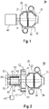
- the power converter 40 is provided in front of the compressor wheel 21, i.e. on an air intake side of the compressor.
- the power converter 40 can be arranged directly in front of the compressor on the air intake side of the compressor ( Fig. 1 ) or an intermediate component, such as a filter silencer 50 as described herein, can be provided between the compressor and the power converter 40.
- turbocharging assembly with a back-to-back configuration of the turbine wheel and the compressor wheel and arranging the power converter provided in front of the compressor wheel
- a more compact design of a turbocharging assembly ca be provided as compared to the state of the art, such that the overall footprint of the turbocharging assembly can be reduced.
- arranging the power converter in front of the compressor wheel is beneficial for protecting the power converter from high temperatures, which typically occur in the vicinity of the turbine during operation.
- the back-to-back configuration of the turbine wheel and the compressor wheel combined with the arrangement of the power converter in front of the compressor wheel has the advantage that the overall mass balancing of the rotating components, particularly the shaft and the wheels, can be improved.
- the power converter particularly components of the power converter coupled to the common shaft, may act as a counter mass with respect to the turbine wheel and the compressor wheel.
- a power converter can be understood as a device which is configured for converting electrical power or hydraulic power into mechanical power, e.g. in case the power converter is an electrical or hydraulic motor. Further, a power converter can also be understood as a device configured converting mechanical power into electrical power, e.g. in case the power converter is an alternator. Accordingly, a power converter as described herein can be an electric power converter or a hydraulic power converter. In particular the power converter as described herein can be a motor, particularly an electrical or hydraulic motor, or an alternator.
- a compressor housing 22 encasing the compressor wheel 21 is connected to a turbine housing 32 encasing the turbine wheel 31.
- each of the compressor housing 22 and the turbine housing 32 may be separate housing, and the compressor housing 22 may be connected with the separate turbine housing 32, for instance via welded, bolted or other mechanical connection.
- the compressor housing 22 may be integrally connected with the turbine housing 32.
- the compressor housing 22 and the turbine housing 32 can be single piece structure forming a common housing.
- the common housing can be an integrated single piece structure of casted material.
- the power converter 40 includes one or more first electromagnetic coils and one or more second electromagnetic coils (not explicitly shown).
- the one or more first electromagnetic coils are coupled with the shaft 11 and the one or more second electromagnetic coils are provided around the one or more first electromagnetic coil.
- the power converter 40 is configured for providing a rotational speed difference between the one or more first electromagnetic coils and the one or more second electromagnetic coils during operation.
- the one or more first electromagnetic coils are mechanically coupled with the shaft 11, such that a rotation of the shaft 11 is transmitted to the one or more first electromagnetic coils.
- the power converter 40 includes a rotor 41 and a stator 42.
- the rotor 41 includes one or more first electromagnetic coils and the stator 42 includes one or more second electromagnetic coils.
- the rotor 41 is connected to the shaft 11.
- the turbocharging assembly 10 further includes a filter silencer 50 arranged between the compressor 20 and the power converter 40, as exemplarily shown in Fig. 2 . Accordingly, the air flow into the compressor can be provided through the filter silencer 50 arranged in-between the compressor 20 and the power converter 40. In other words, as exemplarily indicated in Fig. 2 , the air flow 12 into the filter silencer 50 may be provided between the power converter 40 and the compressor wheel 21, which can be beneficial for protecting the power converter 40 from heat or even cooling the power converter 40.
- the turbocharging assembly 10 further includes a blower 60 mounted to the shaft 11.
- the blower 60 is arranged at a side of the power converter 40 facing away from the compressor 20.
- the blower 60 is a fan configured for providing air towards the power converter 40, i.e. in a direction towards the compressor. Accordingly, the blower 60 may act as a cooler for the power converter 40. Further, the blower 60 can improve the air intake into the compressor 20.
- the turbocharging assembly 10 further includes a housing extension 43 encasing the power converter 40, as exemplarily shown in Fig. 2 .
- the housing extension 43 can be connected with the compressor housing 22.
- the housing extension 43 can be directly connected to the compressor housing 22.
- the housing extension 43 can be connected with the compressor housing 22 via an intermediate component, e.g. the filter silencer 50 as described herein.
- the stator 42 can be mounted to the housing extension 43.
- the stator 42 can be integrated into the housing 43, which may be beneficially for improving compactness and reducing installation space.
- the turbocharging assembly includes power storage 45 coupled to the power converter 40, as exemplarily indicated in Fig. 2 .
- the power storage 45 can be a battery.
- a method of controlling operation of a turbocharging assembly 10 includes controlling a power converter 40.
- the power converter 40 is provided in front of a compressor wheel 21 of a compressor 20.
- the compressor wheel 21 and a turbine wheel 31 of a turbine 30 are mounted back-to-back on a shaft 11 coupled with the power converter 40.
- the turbocharging assembly can be controlled by the power converter, e.g. in order to speed up and reduce the startup time of the turbocharging assembly.
- the power converter can be used to reduce turbo lag during engine transitional operation.
- the power converter can be used for power generation.
Landscapes
- Engineering & Computer Science (AREA)
- Mechanical Engineering (AREA)
- General Engineering & Computer Science (AREA)
- Chemical & Material Sciences (AREA)
- Combustion & Propulsion (AREA)
- Power Engineering (AREA)
- Chemical Kinetics & Catalysis (AREA)
- General Chemical & Material Sciences (AREA)
- Microelectronics & Electronic Packaging (AREA)
- Supercharger (AREA)
- Structures Of Non-Positive Displacement Pumps (AREA)
Priority Applications (7)
| Application Number | Priority Date | Filing Date | Title |
|---|---|---|---|
| EP21160717.1A EP4053388A1 (de) | 2021-03-04 | 2021-03-04 | Turboladeranordnung und verfahren zum steuern des betriebs einer turboladeranordnung |
| PCT/EP2022/055566 WO2022184902A1 (en) | 2021-03-04 | 2022-03-04 | Turbocharging assembly and method of controlling operation of a turbocharging assembly |
| CN202280019083.1A CN117321295A (zh) | 2021-03-04 | 2022-03-04 | 涡轮增压组件及控制涡轮增压组件的操作的方法 |
| EP22709747.4A EP4301968A1 (de) | 2021-03-04 | 2022-03-04 | Turboladeranordnung und verfahren zur steuerung des betriebs einer turboladeranordnung |
| KR1020237032820A KR20230153415A (ko) | 2021-03-04 | 2022-03-04 | 터보차징 조립체 및 터보차징 조립체의 작동을 제어하는 방법 |
| JP2023553589A JP2024508164A (ja) | 2021-03-04 | 2022-03-04 | ターボ過給組立体及びターボ過給組立体の動作を制御する方法 |
| US18/278,592 US12031475B2 (en) | 2021-03-04 | 2022-03-04 | Turbocharging assembly and method of controlling operation of a turbocharging assembly |
Applications Claiming Priority (1)
| Application Number | Priority Date | Filing Date | Title |
|---|---|---|---|
| EP21160717.1A EP4053388A1 (de) | 2021-03-04 | 2021-03-04 | Turboladeranordnung und verfahren zum steuern des betriebs einer turboladeranordnung |
Publications (1)
| Publication Number | Publication Date |
|---|---|
| EP4053388A1 true EP4053388A1 (de) | 2022-09-07 |
Family
ID=74858332
Family Applications (2)
| Application Number | Title | Priority Date | Filing Date |
|---|---|---|---|
| EP21160717.1A Withdrawn EP4053388A1 (de) | 2021-03-04 | 2021-03-04 | Turboladeranordnung und verfahren zum steuern des betriebs einer turboladeranordnung |
| EP22709747.4A Withdrawn EP4301968A1 (de) | 2021-03-04 | 2022-03-04 | Turboladeranordnung und verfahren zur steuerung des betriebs einer turboladeranordnung |
Family Applications After (1)
| Application Number | Title | Priority Date | Filing Date |
|---|---|---|---|
| EP22709747.4A Withdrawn EP4301968A1 (de) | 2021-03-04 | 2022-03-04 | Turboladeranordnung und verfahren zur steuerung des betriebs einer turboladeranordnung |
Country Status (6)
| Country | Link |
|---|---|
| US (1) | US12031475B2 (de) |
| EP (2) | EP4053388A1 (de) |
| JP (1) | JP2024508164A (de) |
| KR (1) | KR20230153415A (de) |
| CN (1) | CN117321295A (de) |
| WO (1) | WO2022184902A1 (de) |
Citations (9)
| Publication number | Priority date | Publication date | Assignee | Title |
|---|---|---|---|---|
| JPS60212622A (ja) * | 1984-04-09 | 1985-10-24 | Ishikawajima Harima Heavy Ind Co Ltd | 過給装置 |
| DE8505239U1 (de) * | 1985-02-23 | 1987-08-20 | M.A.N.- B & W Diesel GmbH, 8900 Augsburg | Schalldämpfer mit Vorleitschaufeln an der Ansaugseite des Verdichters eines Abgasturboladers |
| US6102672A (en) * | 1997-09-10 | 2000-08-15 | Turbodyne Systems, Inc. | Motor-driven centrifugal air compressor with internal cooling airflow |
| US20110239648A1 (en) * | 2009-04-24 | 2011-10-06 | Keiichi Shiraishi | Hybrid exhaust turbine turbocharger |
| US20170167511A1 (en) * | 2014-02-24 | 2017-06-15 | Mitsubishi Heavy Industries, Ltd. | Supercharger and motor cooling method |
| US20180001984A1 (en) * | 2015-01-05 | 2018-01-04 | Mitsubishi Heavy Industries, Ltd. | Device and method for starting internal combustion engine |
| DE102016221639A1 (de) * | 2016-11-04 | 2018-05-09 | Ford Global Technologies, Llc | Aufgeladene Brennkraftmaschine mit gekühltem Verdichter |
| US20190145416A1 (en) * | 2017-11-14 | 2019-05-16 | Garrett Transportation I Inc. | Multi-stage compressor with turbine section for fuel cell system |
| US20200248704A1 (en) * | 2017-09-22 | 2020-08-06 | Robert Bosch Gmbh | Electric media gap machine, and compressor and/or turbine |
Family Cites Families (4)
| Publication number | Priority date | Publication date | Assignee | Title |
|---|---|---|---|---|
| JP3203891B2 (ja) * | 1993-06-30 | 2001-08-27 | いすゞ自動車株式会社 | タ−ボ用回転電機の電力部制御装置 |
| JP2010127239A (ja) * | 2008-11-28 | 2010-06-10 | Mitsubishi Heavy Ind Ltd | 舶用ディーゼル機関 |
| JP6460773B2 (ja) * | 2014-12-19 | 2019-01-30 | 株式会社マーレ フィルターシステムズ | ターボチャージャ |
| US11158871B2 (en) * | 2018-07-18 | 2021-10-26 | GM Global Technology Operations LLC | Fuel cell assembly and a vehicle that utilizes the fuel cell assembly |
-
2021
- 2021-03-04 EP EP21160717.1A patent/EP4053388A1/de not_active Withdrawn
-
2022
- 2022-03-04 CN CN202280019083.1A patent/CN117321295A/zh not_active Withdrawn
- 2022-03-04 KR KR1020237032820A patent/KR20230153415A/ko not_active Withdrawn
- 2022-03-04 WO PCT/EP2022/055566 patent/WO2022184902A1/en not_active Ceased
- 2022-03-04 JP JP2023553589A patent/JP2024508164A/ja not_active Ceased
- 2022-03-04 US US18/278,592 patent/US12031475B2/en active Active
- 2022-03-04 EP EP22709747.4A patent/EP4301968A1/de not_active Withdrawn
Patent Citations (9)
| Publication number | Priority date | Publication date | Assignee | Title |
|---|---|---|---|---|
| JPS60212622A (ja) * | 1984-04-09 | 1985-10-24 | Ishikawajima Harima Heavy Ind Co Ltd | 過給装置 |
| DE8505239U1 (de) * | 1985-02-23 | 1987-08-20 | M.A.N.- B & W Diesel GmbH, 8900 Augsburg | Schalldämpfer mit Vorleitschaufeln an der Ansaugseite des Verdichters eines Abgasturboladers |
| US6102672A (en) * | 1997-09-10 | 2000-08-15 | Turbodyne Systems, Inc. | Motor-driven centrifugal air compressor with internal cooling airflow |
| US20110239648A1 (en) * | 2009-04-24 | 2011-10-06 | Keiichi Shiraishi | Hybrid exhaust turbine turbocharger |
| US20170167511A1 (en) * | 2014-02-24 | 2017-06-15 | Mitsubishi Heavy Industries, Ltd. | Supercharger and motor cooling method |
| US20180001984A1 (en) * | 2015-01-05 | 2018-01-04 | Mitsubishi Heavy Industries, Ltd. | Device and method for starting internal combustion engine |
| DE102016221639A1 (de) * | 2016-11-04 | 2018-05-09 | Ford Global Technologies, Llc | Aufgeladene Brennkraftmaschine mit gekühltem Verdichter |
| US20200248704A1 (en) * | 2017-09-22 | 2020-08-06 | Robert Bosch Gmbh | Electric media gap machine, and compressor and/or turbine |
| US20190145416A1 (en) * | 2017-11-14 | 2019-05-16 | Garrett Transportation I Inc. | Multi-stage compressor with turbine section for fuel cell system |
Also Published As
| Publication number | Publication date |
|---|---|
| US20240133338A1 (en) | 2024-04-25 |
| JP2024508164A (ja) | 2024-02-22 |
| US20240229706A9 (en) | 2024-07-11 |
| EP4301968A1 (de) | 2024-01-10 |
| KR20230153415A (ko) | 2023-11-06 |
| CN117321295A (zh) | 2023-12-29 |
| WO2022184902A1 (en) | 2022-09-09 |
| US12031475B2 (en) | 2024-07-09 |
Similar Documents
| Publication | Publication Date | Title |
|---|---|---|
| US6735945B1 (en) | Electric turbocharging system | |
| EP2247838B1 (de) | Aufladeanordnung für einen kolbenmotor | |
| CN108137161B (zh) | 具有电气驱动压缩机的辅助动力单元 | |
| EP3242002B1 (de) | Turbolader | |
| US6449950B1 (en) | Rotor and bearing system for electrically assisted turbocharger | |
| US8157544B2 (en) | Motor driven supercharger with motor/generator cooling efficacy | |
| EP1749991B1 (de) | Lader mit Elektromotor | |
| KR101536795B1 (ko) | 피스톤 엔진용 터보과급기 장치 | |
| CN107939513B (zh) | 电辅助离合式动力涡轮复合增压器 | |
| US9115642B2 (en) | Turbocharger provided with an electrical machine for a supercharged internal combustion engine | |
| US7044718B1 (en) | Radial-radial single rotor turbine | |
| CN108533387A (zh) | 一种带电机/发电机的涡轮增压装置 | |
| US12031475B2 (en) | Turbocharging assembly and method of controlling operation of a turbocharging assembly | |
| GB2597603A (en) | Exhaust-gas turbocharger and motor vehicle | |
| WO2026029853A1 (en) | Stator cooled electric motor | |
| RU2821119C1 (ru) | Турбогенератор | |
| EP4112902A1 (de) | Kühlmittelsystem für integrierte steuerung für elektrische turbomaschine | |
| CN113931733A (zh) | 一种电动发电涡轮增压器 |
Legal Events
| Date | Code | Title | Description |
|---|---|---|---|
| PUAI | Public reference made under article 153(3) epc to a published international application that has entered the european phase |
Free format text: ORIGINAL CODE: 0009012 |
|
| STAA | Information on the status of an ep patent application or granted ep patent |
Free format text: STATUS: THE APPLICATION HAS BEEN PUBLISHED |
|
| AK | Designated contracting states |
Kind code of ref document: A1 Designated state(s): AL AT BE BG CH CY CZ DE DK EE ES FI FR GB GR HR HU IE IS IT LI LT LU LV MC MK MT NL NO PL PT RO RS SE SI SK SM TR |
|
| STAA | Information on the status of an ep patent application or granted ep patent |
Free format text: STATUS: THE APPLICATION IS DEEMED TO BE WITHDRAWN |
|
| 18D | Application deemed to be withdrawn |
Effective date: 20230308 |