EP4053406A1 - Vanne de commande de capacité - Google Patents
Vanne de commande de capacité Download PDFInfo
- Publication number
- EP4053406A1 EP4053406A1 EP20881943.3A EP20881943A EP4053406A1 EP 4053406 A1 EP4053406 A1 EP 4053406A1 EP 20881943 A EP20881943 A EP 20881943A EP 4053406 A1 EP4053406 A1 EP 4053406A1
- Authority
- EP
- European Patent Office
- Prior art keywords
- valve
- pressure
- control
- fluid
- valve body
- Prior art date
- Legal status (The legal status is an assumption and is not a legal conclusion. Google has not performed a legal analysis and makes no representation as to the accuracy of the status listed.)
- Granted
Links
Images


Classifications
-
- F—MECHANICAL ENGINEERING; LIGHTING; HEATING; WEAPONS; BLASTING
- F04—POSITIVE - DISPLACEMENT MACHINES FOR LIQUIDS; PUMPS FOR LIQUIDS OR ELASTIC FLUIDS
- F04B—POSITIVE-DISPLACEMENT MACHINES FOR LIQUIDS; PUMPS
- F04B27/00—Multi-cylinder pumps specially adapted for elastic fluids and characterised by number or arrangement of cylinders
- F04B27/08—Multi-cylinder pumps specially adapted for elastic fluids and characterised by number or arrangement of cylinders having cylinders coaxial with, or parallel or inclined to, main shaft axis
- F04B27/14—Control
- F04B27/16—Control of pumps with stationary cylinders
- F04B27/18—Control of pumps with stationary cylinders by varying the relative positions of a swash plate and a cylinder block
-
- F—MECHANICAL ENGINEERING; LIGHTING; HEATING; WEAPONS; BLASTING
- F04—POSITIVE - DISPLACEMENT MACHINES FOR LIQUIDS; PUMPS FOR LIQUIDS OR ELASTIC FLUIDS
- F04B—POSITIVE-DISPLACEMENT MACHINES FOR LIQUIDS; PUMPS
- F04B27/00—Multi-cylinder pumps specially adapted for elastic fluids and characterised by number or arrangement of cylinders
- F04B27/08—Multi-cylinder pumps specially adapted for elastic fluids and characterised by number or arrangement of cylinders having cylinders coaxial with, or parallel or inclined to, main shaft axis
- F04B27/14—Control
- F04B27/16—Control of pumps with stationary cylinders
- F04B27/18—Control of pumps with stationary cylinders by varying the relative positions of a swash plate and a cylinder block
- F04B27/1804—Controlled by crankcase pressure
-
- B—PERFORMING OPERATIONS; TRANSPORTING
- B60—VEHICLES IN GENERAL
- B60H—ARRANGEMENTS OF HEATING, COOLING, VENTILATING OR OTHER AIR-TREATING DEVICES SPECIALLY ADAPTED FOR PASSENGER OR GOODS SPACES OF VEHICLES
- B60H1/00—Heating, cooling or ventilating devices
- B60H1/00485—Valves for air-conditioning devices, e.g. thermostatic valves
-
- B—PERFORMING OPERATIONS; TRANSPORTING
- B60—VEHICLES IN GENERAL
- B60H—ARRANGEMENTS OF HEATING, COOLING, VENTILATING OR OTHER AIR-TREATING DEVICES SPECIALLY ADAPTED FOR PASSENGER OR GOODS SPACES OF VEHICLES
- B60H1/00—Heating, cooling or ventilating devices
- B60H1/32—Cooling devices
- B60H1/3204—Cooling devices using compression
- B60H1/3223—Cooling devices using compression characterised by the arrangement or type of the compressor
-
- F—MECHANICAL ENGINEERING; LIGHTING; HEATING; WEAPONS; BLASTING
- F16—ENGINEERING ELEMENTS AND UNITS; GENERAL MEASURES FOR PRODUCING AND MAINTAINING EFFECTIVE FUNCTIONING OF MACHINES OR INSTALLATIONS; THERMAL INSULATION IN GENERAL
- F16K—VALVES; TAPS; COCKS; ACTUATING-FLOATS; DEVICES FOR VENTING OR AERATING
- F16K27/00—Construction of housing; Use of materials therefor
- F16K27/02—Construction of housing; Use of materials therefor of lift valves
- F16K27/029—Electromagnetically actuated valves
-
- F—MECHANICAL ENGINEERING; LIGHTING; HEATING; WEAPONS; BLASTING
- F16—ENGINEERING ELEMENTS AND UNITS; GENERAL MEASURES FOR PRODUCING AND MAINTAINING EFFECTIVE FUNCTIONING OF MACHINES OR INSTALLATIONS; THERMAL INSULATION IN GENERAL
- F16K—VALVES; TAPS; COCKS; ACTUATING-FLOATS; DEVICES FOR VENTING OR AERATING
- F16K31/00—Actuating devices; Operating means; Releasing devices
- F16K31/02—Actuating devices; Operating means; Releasing devices electric; magnetic
- F16K31/06—Actuating devices; Operating means; Releasing devices electric; magnetic using a magnet, e.g. diaphragm valves, cutting off by means of a liquid
-
- F—MECHANICAL ENGINEERING; LIGHTING; HEATING; WEAPONS; BLASTING
- F16—ENGINEERING ELEMENTS AND UNITS; GENERAL MEASURES FOR PRODUCING AND MAINTAINING EFFECTIVE FUNCTIONING OF MACHINES OR INSTALLATIONS; THERMAL INSULATION IN GENERAL
- F16K—VALVES; TAPS; COCKS; ACTUATING-FLOATS; DEVICES FOR VENTING OR AERATING
- F16K31/00—Actuating devices; Operating means; Releasing devices
- F16K31/02—Actuating devices; Operating means; Releasing devices electric; magnetic
- F16K31/06—Actuating devices; Operating means; Releasing devices electric; magnetic using a magnet, e.g. diaphragm valves, cutting off by means of a liquid
- F16K31/0675—Electromagnet aspects, e.g. electric supply therefor
-
- B—PERFORMING OPERATIONS; TRANSPORTING
- B60—VEHICLES IN GENERAL
- B60H—ARRANGEMENTS OF HEATING, COOLING, VENTILATING OR OTHER AIR-TREATING DEVICES SPECIALLY ADAPTED FOR PASSENGER OR GOODS SPACES OF VEHICLES
- B60H1/00—Heating, cooling or ventilating devices
- B60H1/32—Cooling devices
- B60H2001/3269—Cooling devices output of a control signal
- B60H2001/327—Cooling devices output of a control signal related to a compressing unit
- B60H2001/3275—Cooling devices output of a control signal related to a compressing unit to control the volume of a compressor
-
- F—MECHANICAL ENGINEERING; LIGHTING; HEATING; WEAPONS; BLASTING
- F04—POSITIVE - DISPLACEMENT MACHINES FOR LIQUIDS; PUMPS FOR LIQUIDS OR ELASTIC FLUIDS
- F04B—POSITIVE-DISPLACEMENT MACHINES FOR LIQUIDS; PUMPS
- F04B27/00—Multi-cylinder pumps specially adapted for elastic fluids and characterised by number or arrangement of cylinders
- F04B27/08—Multi-cylinder pumps specially adapted for elastic fluids and characterised by number or arrangement of cylinders having cylinders coaxial with, or parallel or inclined to, main shaft axis
- F04B27/14—Control
- F04B27/16—Control of pumps with stationary cylinders
- F04B27/18—Control of pumps with stationary cylinders by varying the relative positions of a swash plate and a cylinder block
- F04B27/1804—Controlled by crankcase pressure
- F04B2027/1809—Controlled pressure
- F04B2027/1818—Suction pressure
-
- F—MECHANICAL ENGINEERING; LIGHTING; HEATING; WEAPONS; BLASTING
- F04—POSITIVE - DISPLACEMENT MACHINES FOR LIQUIDS; PUMPS FOR LIQUIDS OR ELASTIC FLUIDS
- F04B—POSITIVE-DISPLACEMENT MACHINES FOR LIQUIDS; PUMPS
- F04B27/00—Multi-cylinder pumps specially adapted for elastic fluids and characterised by number or arrangement of cylinders
- F04B27/08—Multi-cylinder pumps specially adapted for elastic fluids and characterised by number or arrangement of cylinders having cylinders coaxial with, or parallel or inclined to, main shaft axis
- F04B27/14—Control
- F04B27/16—Control of pumps with stationary cylinders
- F04B27/18—Control of pumps with stationary cylinders by varying the relative positions of a swash plate and a cylinder block
- F04B27/1804—Controlled by crankcase pressure
- F04B2027/1822—Valve-controlled fluid connection
- F04B2027/1831—Valve-controlled fluid connection between crankcase and suction chamber
-
- F—MECHANICAL ENGINEERING; LIGHTING; HEATING; WEAPONS; BLASTING
- F04—POSITIVE - DISPLACEMENT MACHINES FOR LIQUIDS; PUMPS FOR LIQUIDS OR ELASTIC FLUIDS
- F04B—POSITIVE-DISPLACEMENT MACHINES FOR LIQUIDS; PUMPS
- F04B27/00—Multi-cylinder pumps specially adapted for elastic fluids and characterised by number or arrangement of cylinders
- F04B27/08—Multi-cylinder pumps specially adapted for elastic fluids and characterised by number or arrangement of cylinders having cylinders coaxial with, or parallel or inclined to, main shaft axis
- F04B27/14—Control
- F04B27/16—Control of pumps with stationary cylinders
- F04B27/18—Control of pumps with stationary cylinders by varying the relative positions of a swash plate and a cylinder block
- F04B27/1804—Controlled by crankcase pressure
- F04B2027/184—Valve controlling parameter
- F04B2027/185—Discharge pressure
-
- F—MECHANICAL ENGINEERING; LIGHTING; HEATING; WEAPONS; BLASTING
- F04—POSITIVE - DISPLACEMENT MACHINES FOR LIQUIDS; PUMPS FOR LIQUIDS OR ELASTIC FLUIDS
- F04B—POSITIVE-DISPLACEMENT MACHINES FOR LIQUIDS; PUMPS
- F04B27/00—Multi-cylinder pumps specially adapted for elastic fluids and characterised by number or arrangement of cylinders
- F04B27/08—Multi-cylinder pumps specially adapted for elastic fluids and characterised by number or arrangement of cylinders having cylinders coaxial with, or parallel or inclined to, main shaft axis
- F04B27/14—Control
- F04B27/16—Control of pumps with stationary cylinders
- F04B27/18—Control of pumps with stationary cylinders by varying the relative positions of a swash plate and a cylinder block
- F04B27/1804—Controlled by crankcase pressure
- F04B2027/1863—Controlled by crankcase pressure with an auxiliary valve, controlled by
- F04B2027/1877—External parameters
Definitions
- the present invention relates to a capacity control valve that variably controls capacity of a working fluid, for example, a capacity control valve that controls a discharge amount of a variable displacement compressor used for an air conditioning system of an automobile according to pressure.
- a variable displacement compressor used for an air conditioning system of an automobile, etc. includes a rotating shaft to be driven and rotated by an engine, a swash plate coupled to the rotating shaft in such a manner that a tilt angle is variable, compressing pistons coupled to the swash plate, etc., and by changing the tilt angle of the swash plate, changes a stroke amount of the pistons to control a discharge amount of a fluid.
- This tilt angle of the swash plate can be continuously changed by appropriately controlling pressure in a control chamber while utilizing a suction pressure Ps of a suction chamber that suctions the fluid, a discharge pressure Pd of a discharge chamber that discharges the fluid pressurized by the pistons, and a control pressure Pc of the control chamber that houses the swash plate, by means of a capacity control valve to be driven to open and close by electromagnetic force.
- the capacity control valve performs normal control in which energization is controlled by a control computer, a valve body is moved in an axial direction by electromagnetic force generated in a solenoid, and a CS valve provided between a control port through which a control fluid of the control pressure Pc passes and a suction port through which a suction fluid of the suction pressure Ps passes is opened and closed to adjust the control pressure Pc of the control chamber of the variable displacement compressor.
- the pressure of the control chamber in the variable displacement compressor is appropriately controlled, and the tilt angle of the swash plate with respect to the rotating shaft is continuously changed, so that the stroke amount of the pistons is changed, and the discharge amount of the fluid to the discharge chamber is controlled, and thereby the air conditioning system is adjusted to a target cooling capacity.
- a capacity control valve of Patent Citation 1 changes the discharge amount of the fluid to be discharged from the discharge chamber by opening and closing the CS valve to control the fluid of the control pressure Pc to be released from the control chamber to the suction chamber of the variable displacement compressor, and bringing a pressure difference between the discharge pressure Pd of the discharge chamber and the control pressure Pc of the control chamber, each of which is applied in a stroke direction of the pistons, to a target value.
- the valve opening degree of the CS valve changes according to an electromagnetic force due to an electric current applied to the solenoid, the target value of the pressure difference is changed according to the change, and the discharge amount of the fluid to be discharged from the discharge chamber is changed.
- a pressure-sensitive portion including a diaphragm is provided in a pressure-sensitive chamber of the capacity control valve, and the pressure-sensitive portion changes a force to move the valve body according to the suction pressure Ps to adjust the valve opening degree of the CS valve.
- the suction fluid of the suction pressure Ps to be supplied to the pressure-sensitive chamber is guided to a back side of the valve body through a communication passage formed in a shaft and a plunger that form the valve body and the solenoid, and influences of the suction pressure Ps applied to both sides of the valve body in a movement direction are cancelled out.
- Patent Citation 1 JP 2011-94554 A (PAGE 10, FIG. 2 )
- the present invention has been made in view of such problems, and an object of the present invention is to provide a capacity control valve capable of improving responsiveness.
- a capacity control valve includes: a valve housing provided with a suction port through which a suction fluid of a suction pressure passes and a control port through which a control fluid of a control pressure passes; a valve body to be driven by a solenoid; a spring that biases the valve body in a direction opposite to a direction of driving by the solenoid; and a CS valve that includes a CS valve seat and the valve body, and that moves the valve body to open and close a communication between the control port and the suction port, the capacity control valve opening and closing the CS valve to control the control pressure, in which the control fluid of the control pressure is suppliable to a back side of the valve body, and the capacity control valve further includes a flow passage control device that uses a fluid pressure generated by opening and closing of the CS valve and a pressure on the back side of the valve body to decrease the pressure on the back side of the valve body.
- the flow passage control device uses a pressure difference between the fluid pressure generated by opening and closing of the CS valve, and the pressure on the back side of the valve body to discharge the fluid on the back side of the valve body through a flow passage, so that the pressure on the back side of the valve body can be decreased to reduce an influence of the control pressure which is applied to the valve body. Therefore, the responsiveness of the capacity control valve can be improved.
- the flow passage control device includes an actuating valve body and a biasing device, and the flow passage control device is a valve in which a force due to the fluid pressure and a biasing force of the biasing device are opposed to a force due to the pressure on the back side of the valve body.
- the actuating valve body biased by the biasing device can be operated according to the pressure difference between the fluid pressure generated because of a decrease in the control pressure by opening of the CS valve, and the pressure on the back side of the valve body, the flow passage control device for decreasing the pressure on the back side of the valve body can be simply configured.
- the fluid pressure is a pressure on a downstream side of the CS valve, and the biasing device biases the actuating valve body in a valve opening direction.
- the flow passage control device can be configured to open the flow passage that discharges the fluid on the back side of the valve body when the sum of the force due to the fluid pressure and the biasing force of the biasing device is larger than the force due to the pressure on the back side of the valve body, and the pressure on the back side of the valve body can be rapidly decreased to further improve responsiveness of the capacity control valve.
- the upstream side and the downstream side of the CS valve are a control port side and a suction port side of the CS valve, respectively, and the same applies to the following description.
- the fluid pressure is a pressure on an upstream side of the CS valve, and the biasing device biases the actuating valve body in a valve closing direction.
- the flow passage control device can be configured to open the flow passage that discharges the fluid on the back side of the valve body when the sum of the force due to the fluid pressure and the biasing force of the biasing device is smaller than the force due to the pressure on the back side of the valve body, and a state where a pressure difference between the pressure on the back side of the valve body and the pressure on the upstream side of the CS valve is small is maintained. Therefore, the controllability of the capacity control valve can be improved.
- the capacity control valve further includes a pressure-actuated valve to be actuated to open and close a communication between an upstream side of the CS valve and the back side of the valve body by a pressure difference.
- a pressure-actuated valve to be actuated to open and close a communication between an upstream side of the CS valve and the back side of the valve body by a pressure difference.
- the flow passage control device is provided in a through-hole of the valve housing, the through-hole communicating with the suction port. According to this preferable configuration, since the flow passage control device can be formed using the through-hole of the valve housing, the through-hole communicating with the existing suction port, the structure of the capacity control valve can be simplified.
- the flow passage control device is provided in a through-hole of the valve housing, the through-hole communicating with the upstream side of the CS valve. According to this preferable configuration, since the flow passage control device can be formed using the through-hole of the valve housing, the structure of the capacity control valve can be simplified.
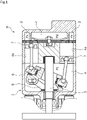
- FIGS. 1 to 5 A capacity control valve according to a first embodiment of the present invention will be described with reference to FIGS. 1 to 5 .
- right and left sides of FIG. 2 as viewed from a front side are right and left sides of the capacity control valve.
- a description will be given based on the assumption that the left side of the drawing sheet on which a valve housing 10 is disposed is the left side of the capacity control valve and the right side of the drawing sheet on which a solenoid 80 is disposed is the right side of the capacity control valve.
- a capacity control valve V of the present invention is assembled into a variable displacement compressor M used for an air conditioning system of an automobile, etc., and by variably controlling the pressure of a working fluid (hereinafter, simply referred to as a "fluid") which is a refrigerant, controls a discharge amount of the variable displacement compressor M to adjust the air conditioning system to a target cooling capacity.
- a working fluid hereinafter, simply referred to as a "fluid" which is a refrigerant
- the variable displacement compressor M includes a casing 1 including a discharge chamber 2, a suction chamber 3, a control chamber 4, and a plurality of cylinders 4a.
- the variable displacement compressor M is provided with a communication passage through which the discharge chamber 2 and the control chamber 4 directly communicate with each other, and the communication passage is provided with a fixed orifice 9 that adjusts and balances the pressures of the discharge chamber 2 and the control chamber 4 (see FIG. 2 ).
- variable displacement compressor M includes a rotating shaft 5 to be driven and rotated by an engine (not shown) installed outside the casing 1; a swash plate 6 coupled to the rotating shaft 5 so as to be tiltable by a hinge mechanism 8 in the control chamber 4; and a plurality of pistons 7 coupled to the swash plate 6 and reciprocatably fitted in the respective cylinders 4a.
- the tilt angle of the swash plate 6 is continuously changed by appropriately controlling pressure in the control chamber 4 while utilizing a suction pressure Ps of the suction chamber 3 that suctions the fluid, a discharge pressure Pd of the discharge chamber 2 that discharges the fluid pressurized by the pistons 7, and a control pressure Pc of the control chamber 4 that houses the swash plate 6, by means of the capacity control valve V to be driven to open and close by electromagnetic force.
- the stroke amount of the pistons 7 is changed to control the discharge amount of the fluid.
- the capacity control valve V assembled into the variable displacement compressor M is not shown in FIG. 1 .
- the control pressure Pc reaches a certain pressure or higher, the swash plate 6 is substantially perpendicular to the rotating shaft 5, namely, is slightly tilted from perpendicularity.
- the stroke amount of the pistons 7 is minimized and the pressurization of the fluid in the cylinders 4a by the pistons 7 is minimized, the discharge amount of the fluid to the discharge chamber 2 is reduced, and the cooling capacity of the air conditioning system is minimized.
- the control pressure Pc reaches a certain pressure or lower, the swash plate 6 forms a maximum tilt angle with respect to the rotating shaft 5.
- the stroke amount of the pistons 7 is maximized and the pressurization of the fluid in the cylinders 4a by the pistons 7 is maximized, the discharge amount of the fluid to the discharge chamber 2 is increased, and the cooling capacity of the air conditioning system is maximized.
- the capacity control valve V assembled into the variable displacement compressor M adjusts electric current which energizes a coil 86 forming the solenoid 80, and controls the opening and closing of a CS valve 50 in the capacity control valve V, to control the fluid flowing out from the control chamber 4 to the suction chamber 3, and thereby the control pressure Pc in the control chamber 4 is variably controlled.
- a discharge fluid of the discharge pressure Pd of the discharge chamber 2 is always supplied to the control chamber 4 via the fixed orifice 9, and the CS valve 50 in the capacity control valve V is closed to increase the control pressure Pc in the control chamber 4.
- the CS valve 50 includes a CS valve body 51 as a valve body, and a CS valve seat 10a formed in an inner peripheral surface of the valve housing 10.
- An axially left end 52a of a large-diameter portion 52 of the CS valve body 51 comes into contact with and separates from the CS valve seat 10a to open and close the CS valve 50.
- the capacity control valve V mainly includes the valve housing 10 made of a metallic material or a resin material; the CS valve body 51 of which an axially left end portion is disposed inside the valve housing 10; and the solenoid 80 connected to the valve housing 10 to exert a driving force on the CS valve body 51.
- the CS valve body 51 includes the large-diameter portion 52 that is a columnar body having a constant cross section, and a small-diameter portion 54 having a smaller diameter than that of the large-diameter portion 52 and extending rightward in an axial direction, and also serves as a rod that is disposed through the coil 86 of the solenoid 80.
- the solenoid 80 mainly includes a casing 81 including an opening portion 81a that is open leftward in the axial direction; a center post 82 that has a substantially cylindrical shape, and that is inserted into the opening portion 81a of the casing 81 from the left in the axial direction to be disposed between a radially inner side of the casing 81 and a radially inner side of the valve housing 10; the CS valve body 51 which is inserted into the center post 82 to be reciprocatable in the axial direction, and of which the axially left end portion is disposed inside the valve housing 10; a movable iron core 84 to which an axially right end portion of the CS valve body 51 is inserted and fixed; a coil spring 85 as a spring provided between the center post 82 and the movable iron core 84 to bias the movable iron core 84 rightward in the axial direction, which is a valve opening direction of the CS valve 50; and the coil 86 for excitation wound
- the center post 82 is made of a rigid body that is a magnetic material such as iron or silicon steel, and includes a cylindrical portion 82b provided with an insertion hole 82c into which the CS valve body 51 extending in the axial direction is inserted, and a flange portion 82d having an annular shape and extending from an outer peripheral surface of an axially left end portion of the cylindrical portion 82b in a radially outward direction.
- a Ps port 11 is formed in the valve housing 10, as a suction port that penetrates through the valve housing 10 in the radial direction to communicate with the suction chamber 3 of the variable displacement compressor M.
- a Pc port 12 is formed on a radially inner side of an axially left end of the valve housing 10, as a control port that communicates with the control chamber 4 of the variable displacement compressor M.
- a valve chamber 20 is formed inside the valve housing 10, and the axially left end 52a of the large-diameter portion 52 of the CS valve body 51 is disposed in the valve chamber 20 so as to be reciprocatable in the axial direction.
- the Ps port 11 extends from an outer peripheral surface of the valve housing 10 in a radially inward direction to communicate with the valve chamber 20.
- the Pc port 12 extends rightward from the radially inner side of the axially left end of the valve housing 10 in the axial direction to communicate with the valve chamber 20.
- the CS valve seat 10a is formed in the inner peripheral surface of the valve housing 10 at an opening end edge on a valve chamber 20 side of the Pc port 12.
- the CS valve seat 10a, and a guide hole 10b against which an outer peripheral surface of the CS valve body 51 is slidable on a solenoid 80 side of the valve chamber 20 are formed in the inner peripheral surface of the valve housing 10.
- the CS valve seat 10a and the guide hole 10b are integrally formed in the inner peripheral surface of the valve housing 10.
- an inner peripheral surface of the guide hole 10b and the outer peripheral surface of the CS valve body 51 are slightly separated from each other in a radial direction to form a very small gap therebetween.
- the CS valve body 51 is smoothly movable relative to the valve housing 10 in the axial direction.
- a recessed portion 10c recessed leftward in the axial direction is formed on an axially right side of the valve housing 10, and the flange portion 82d of the center post 82 is inserted and fixed to the recessed portion 10c from the right in the axial direction in a substantially sealed manner, and the casing 81 is inserted and fixed to the valve housing 10 from the right in the axial direction in a substantially sealed manner, so that the valve housing 10, the center post 82, and the casing 81 are integrally connected to each other.
- an opening end on the solenoid 80 side of the guide hole 10b is formed on a radially inner side of a bottom surface of the recessed portion 10c of the valve housing 10.
- a through-hole 21 extending in the axial direction between an axially left end surface of the valve housing 10 and a bottom portion of the recessed portion 10c is formed in the valve housing 10.
- the through-hole 21 includes a small-diameter hole portion 211 of which an axially left end communicates with the control chamber 4 of the variable displacement compressor M, and a large-diameter hole portion 212 extending continuously from an axially right end of the small-diameter hole portion 211 and having a larger diameter than that of the small-diameter hole portion 211.
- An axially right end of the large-diameter hole portion 212 is open to the gap formed between the bottom surface of the recessed portion 10c and the axially left end surface of the center post 82.
- the control fluid of the control pressure Pc is supplied into the Pc port 12 and the small-diameter hole portion 211 of the through-hole 21 from the control chamber 4 of the variable displacement compressor M.
- An actuating valve body 31 having a ball shape, and a return spring 32 of which an axially right end is fixed to the axially left end surface of the center post 82 and of which an axially left end abuts against the actuating valve body 31 from the right in the axial direction are disposed in the large-diameter hole portion 212 of the through-hole 21.
- the actuating valve body 31 is biased leftward in the axial direction by the return spring 32.
- the actuating valve body 31 and the return spring 32 form a first pressure-actuated valve 30 as a pressure-actuated valve that controls a communication between the control chamber 4 of the variable displacement compressor M and an internal space S of the casing 81 in the through-hole 21 that is a flow passage.
- the internal space S of the casing 81 communicates with an internal space of the center post 82 and the gap formed between the bottom surface of the recessed portion 10c of the valve housing 10 and the axially left end surface of the center post 82.
- a through-hole 22 extending in the axial direction between an inner peripheral surface of the Ps port 11 that is a through-hole extending in the radial direction, and the bottom portion of the recessed portion 10c at the axially right end is formed in the valve housing 10.
- the through-hole 22 includes a small-diameter hole portion 221 of which an axially left end communicates with the inside of the Ps port 11, and a large-diameter hole portion 222 extending continuously from an axially right end of the small-diameter hole portion 221 and having a larger diameter than that of the small-diameter hole portion 221.
- An axially right end of the large-diameter hole portion 222 is open to the gap formed between the bottom surface of the recessed portion 10c of the valve housing 10 and an axially left end of the center post 82.
- the pressure in the valve chamber 20, inside the Ps port 11, and inside the small-diameter hole portion 221 in the valve housing 10 is a fluid pressure that is generated on a downstream side of the CS valve 50 by opening and closing of the CS valve 50.
- An actuating valve body 41 having a ball shape and a return spring 42 as a biasing device of which an axially left end is fixed inside the small-diameter hole portion 221 and of which an axially right end abuts against the actuating valve body 41 from the left in the axial direction are disposed in the large-diameter hole portion 222 and the small-diameter hole portion 221 of the through-hole 22.
- the actuating valve body 41 is biased rightward in the axial direction.
- the actuating valve body 41 and the return spring 42 form a second pressure-actuated valve 40 as a flow passage control device for controlling a communication between the Ps port 11 and the internal space S of the casing 81 in the through-hole 22 that is a flow passage.
- the internal space S of the casing 81 always communicates with the Ps port 11 via a throttle.
- the very small gap between the inner peripheral surface of the guide hole 10b and the outer peripheral surface of the CS valve body 51 functions as a throttle.
- the fluid in the internal space S of the casing 81 can be gently released to the Ps port 11, and a state where a pressure difference between the pressure of the fluid in the valve chamber 20 and the pressure of the fluid in the internal space S of the casing 81 is small is maintained during non-use for a long time.
- the biasing force F sp1 of the coil spring 85, and a force F P1 due to the pressure of the fluid on an axially left end surface of the CS valve body 51 are applied rightward to the CS valve body 51 in the axial direction, and a force F P2 due to the pressure of the fluid on an axially right end surface of the CS valve body 51 is applied leftward in the axial direction.
- a force F rod F sp1 + F P1 - F P2 is applied to the CS valve body 51, given that a right direction is positive.
- the force F P1 due to the pressure of the fluid on the axially left end surface of the CS valve body 51 is a force due to the pressure of the fluid in the valve chamber 20, which is applied to the axially left end 52a of the large-diameter portion 52 of the CS valve body 51.
- the force F P2 due to the pressure of the fluid on the axially right end surface of the CS valve body 51 is a force due to the pressure of the fluid that has flowed around from the valve chamber 20 to a back side of the CS valve body 51 through the gap between the inner peripheral surface of the guide hole 10b of the valve housing 10 and the outer peripheral surface of the CS valve body 51, namely, the pressure of the fluid existing in the internal space S of the casing 81.
- the force F P1 due to the pressure of the fluid on the axially left end surface of the CS valve body 51 is relatively higher than the force F P2 due to the pressure of the fluid on the axially right end surface of the CS valve body 51 (i.e., F P1 > F P2 ).
- an energized state of the capacity control valve V will be described with reference to FIG. 4 .
- the capacity control valve V when the capacity control valve V is in the energized state, namely, in normal control, in other words, in duty control, if an electromagnetic force F sol generated by the application of an electric current to the solenoid 80 is larger than the force F rod (i.e., F sol > F rod ), the movable iron core 84 is pulled toward a center post 82 side, namely, to the axially left side, and the CS valve body 51 fixed to the movable iron core 84 moves together leftward in the axial direction, so that the axially left end 52a of the CS valve body 51 is seated on the CS valve seat 10a of the valve housing 10 to close the CS valve 50.
- the electromagnetic force F sol to the left in the axial direction and the force F rod to the right in the axial direction are applied to the CS valve body 51 (namely, a force F rod - F sol is applied to the CS valve body 51, given that the right direction is positive).
- the force F P1 due to the pressure of the fluid on the axially left end surface of the CS valve body 51 is a force due to the control pressure Pc of the control fluid inside the Pc port 12.
- the actuating valve body 31 of the first pressure-actuated valve 30 moves rightward in the axial direction against a biasing force of the return spring 32 and the pressure of the fluid in the internal space S of the casing 81 to separate from a tapered valve seat 213 formed in a connecting portion between the axially right end of the small-diameter hole portion 211 and the axially left end of the large-diameter hole portion 212 of the through-hole 21, so that the first pressure-actuated valve 30 is opened.
- control chamber 4 of the variable displacement compressor M and the internal space S of the casing 81 communicate with each other through the through-hole 21, the control fluid of the control pressure Pc is supplied from the control chamber 4 of the variable displacement compressor M to the internal space S of the casing 81 through the through-hole 21, and the pressure difference between the control pressure Pc of the control chamber 4 of the variable displacement compressor M and the pressure of the fluid in the internal space S of the casing 81 is reduced.
- a force F P22 due to the pressure of the fluid in the internal space S of the casing 81 which is larger than a combined force of the biasing force F sp21 of the return spring 42 and a force F P21 due to the pressure of the fluid inside the small-diameter hole portion 221 is applied leftward to the actuating valve body 41 in the axial direction (i.e., F sp21 + F P21 ⁇ F P22 , and shown by a white arrow in FIG. 4 ) .
- the Ps port 11 and the internal space S of the casing 81 enter a non-communication state, and the fluid supplied from the control chamber 4 of the variable displacement compressor M to the internal space S of the casing 81 through the through-hole 21 is not discharged to the Ps port 11 through the through-hole 22.
- the pressure of the fluid in the internal space S of the casing 81 can be efficiently increased.
- the combined force of the biasing force F sp21 of the return spring 42 and the force F P21 due to the pressure on the downstream side of the CS valve 50 namely, the pressure of the fluid inside the small-diameter hole portion 221, which is larger than the force F P22 due to the pressure of the fluid in the internal space S of the casing 81, is applied rightward to the actuating valve body 41 in the axial direction (i.e., F sp21 + F P21 > F P22 , and shown by a white arrow in FIG. 5 ).
- the internal space S of the casing 81 and the Ps port 11 communicate with each other through the through-hole 22, the fluid in the internal space S of the casing 81 is discharged from the internal space S of the casing 81 to the Ps port 11 through the through-hole 22, and the pressure of the fluid in the internal space S of the casing 81 decreases rapidly.
- the pressure difference between the control pressure Pc of the control fluid inside the Pc port 12 and the pressure of the fluid in the internal space S of the casing 81 is reduced.
- the biasing force is applied leftward to the actuating valve body 31 of the first pressure-actuated valve 30 in the axial direction, namely, in the valve closing direction by the return spring 32, and the actuating valve body 31 is seated on the valve seat 213, so that the first pressure-actuated valve 30 is closed in a substantially sealed manner.
- control chamber 4 of the variable displacement compressor M and the internal space S of the casing 81 enter a non-communication state, and the supply of the control fluid of the control pressure Pc to the internal space S of the casing 81 is cut off.
- the pressure of the fluid in the internal space S of the casing 81 can be decreased more rapidly because of opening of the second pressure-actuated valve 40 described above, and responsiveness to control for the CS valve 50 to start opening from a valve closed state can be further improved.
- the flow passage control device of the present embodiment is formed of the second pressure-actuated valve 40 in which a force due to the fluid pressure on the downstream side of the CS valve 50, namely, the force F P21 due to the pressure of the fluid inside the small-diameter hole portion 221 of the through-hole 22 communicating with the Ps port 11, and the biasing force F sp21 of the return spring 42 are opposed to the force F P22 due to the pressure of the fluid in the internal space S of the casing 81.
- a flow passage can be reliably opened and closed which discharges the pressure of the fluid in the internal space S of the casing 81 according to a pressure difference between the fluid pressure on the downstream side of the CS valve 50 generated by opening and closing of the CS valve 50, and the pressure of the fluid in the internal space S of the casing 81, and the reliability of the opening and closing operation of the second pressure-actuated valve 40 is high.
- the second pressure-actuated valve 40 is capable of operating the actuating valve body 41 biased by the return spring 42 according to the pressure difference between the fluid pressure generated because of a decrease in the control pressure Pc by opening of the CS valve 50, and the pressure of the fluid in the internal space S of the casing 81, the flow passage control device for decreasing the pressure of the fluid in the internal space S of the casing 81 can be simply configured.
- the second pressure-actuated valve 40 is provided in the through-hole 22 of the valve housing 10 which communicates with the Ps port 11, and the flow passage control device can be formed using the through-hole 22 communicating with the existing Ps port 11, the structure of the capacity control valve V can be simplified.
- the CS valve seat 10a and the guide hole 10b are integrally formed in the valve housing 10, the accuracy of operation of the CS valve body 51 can be improved.
- a capacity control valve according to a second embodiment of the present invention will be described with reference to FIGS. 6 to 9 . Incidentally, a description of the same and duplicated configurations as the configurations of the first embodiment will be omitted.
- a through-hole 23 extending in the axial direction between an axially left end surface and the bottom portion of the recessed portion 10c is formed in the valve housing 110.
- the through-hole 23 includes a large-diameter hole portion 231 of which an axially left end communicates with the control chamber 4 of the variable displacement compressor M, and a small-diameter hole portion 232 extending continuously from an axially right end of the large-diameter hole portion 231 and having a smaller diameter than that of the large-diameter hole portion 231.
- the pressure inside the Pc port 12, inside the small-diameter hole portion 211 of the through-hole 21, and inside the large-diameter hole portion 231 of the through-hole 23 in the valve housing 110 is a fluid pressure on an upstream side of the CS valve 50, namely, the control pressure Pc of the control fluid to be supplied from the control chamber 4 of the variable displacement compressor M.
- the actuating valve body 61 is biased rightward in the axial direction by the return spring 62.
- the actuating valve body 61 and the return spring 62 form a second pressure-actuated valve 60 as a flow passage control device for controlling a communication between the upstream side of the CS valve 50 and the internal space S of the casing 81.
- the actuating valve body 61 of the second pressure-actuated valve 60 is moved rightward in the axial direction by a biasing force of the return spring 62 and the pressure of the fluid inside the large-diameter hole portion 231 of the through-hole 23 to be seated on a tapered valve seat 233 formed in a connecting portion between the axially right end of the large-diameter hole portion 231 and an axially left end of the small-diameter hole portion 232 of the through-hole 23, so that the second pressure-actuated valve 60 is closed in a substantially sealed manner.
- control chamber 4 of the variable displacement compressor M and the internal space S of the casing 81 communicate with each other through the through-hole 21, the control fluid of the control pressure Pc is supplied from the control chamber 4 of the variable displacement compressor M to the internal space S of the casing 81 through the through-hole 21, and the pressure difference between the control pressure Pc of the control chamber 4 of the variable displacement compressor M and the pressure of the fluid in the internal space S of the casing 81 is reduced.
- the actuating valve body 61 of the second pressure-actuated valve 60 is pressed against the valve seat 233 mainly by the biasing force of the return spring 62, and a state where the second pressure-actuated valve 60 is closed in a substantially sealed manner is maintained.
- the actuating valve body 61 of the second pressure-actuated valve 60 moves leftward in the axial direction against the biasing force of the return spring 62 and the force due to the pressure of the fluid inside the large-diameter hole portion 231 to separate from the valve seat 233, so that the second pressure-actuated valve 60 is opened.
- the force F P32 due to the pressure of the fluid in the internal space S of the casing 81 which is larger than a combined force of the biasing force F sp31 of the return spring 62 and the force F P31 due to the pressure of the fluid inside the large-diameter hole portion 231 is applied leftward to the actuating valve body 61 in the axial direction (i.e., F P31 + F sp31 ⁇ F P32 , and shown by a white arrow in FIG. 9 ) .
- the internal space S of the casing 81 and the control chamber 4 of the variable displacement compressor M communicate with each other through the through-hole 23, the fluid in the internal space S of the casing 81 is discharged from the internal space S of the casing 81 through the through-hole 23, the Pc port 12, and the Ps port 11, and the pressure of the fluid in the internal space S of the casing 81 decreases rapidly.
- the pressure difference between the control pressure Pc of the control fluid inside the Pc port 12 and the pressure of the fluid in the internal space S of the casing 81 is reduced.
- the second pressure-actuated valve 60 is closed, and the second pressure-actuated valve 60 is repeatedly opened and closed according to the pressure difference between the pressure of the fluid inside the large-diameter hole portion 231 and the pressure of the fluid in the internal space S of the casing 81.
- the biasing force is applied leftward to the actuating valve body 31 of the first pressure-actuated valve 30 in the axial direction, namely, in the valve closing direction by the return spring 32, and the actuating valve body 31 is seated on the valve seat 213, so that the first pressure-actuated valve 30 is closed in a substantially sealed manner.
- the pressure difference between the control pressure Pc and the pressure of the fluid in the internal space S of the casing 81 is easily adjusted by the opening and closing operation of the second pressure-actuated valve 60 described above.
- the flow passage control device of the present embodiment is formed of the second pressure-actuated valve 60 in which a force due to the fluid pressure on the upstream side of the CS valve 50, namely, the force F P31 due to the pressure of the fluid inside the large-diameter hole portion 231 and the biasing force F sp21 of the return spring 62 are opposed to the force F P32 due to the pressure of the fluid in the internal space S of the casing 81.
- a flow passage can be reliably opened and closed which discharges the pressure of the fluid in the internal space S of the casing 81 according to a pressure difference between the fluid pressure on the upstream side of the CS valve 50 generated by opening and closing of the CS valve 50, namely, the control pressure Pc and the pressure of the fluid in the internal space S of the casing 81, and the reliability of the opening and closing operation of the second pressure-actuated valve 60 is high.
- the second pressure-actuated valve 60 is provided in the through-hole 23 of the valve housing 110 which communicates with the control chamber 4 of the variable displacement compressor M, and the flow passage control device can be formed using the through-hole 23 formed in the existing valve housing 110, the structure of the capacity control valve V can be simplified.
- the mode has been described in which the CS valve body is provided in a drive rod that is disposed through the coil 86 of the solenoid 80; however, the present invention is not limited to the mode, and the CS valve body may be configured to be reciprocatable integrally with a separate rod in the axial direction.
- the CS valve seat and the guide hole have been described as being integrally formed in the inner peripheral surface of the valve housing; however, the present invention is not limited thereto, and a valve housing including the CS valve seat and a valve housing including the guide hole may be provided separately.
- a guide portion is not limited to being formed in the valve housing, and may be formed, for example, in a part of the insertion hole 82c of the center post 82.
- the CS valve body 51 has been described as being biased in the axial direction by the coil spring 85 forming the solenoid 80; however, the present invention is not limited thereto, and an auxiliary spring that biases the CS valve body in the axial direction may be provided in the axially left end portion of the CS valve body, and the CS valve body may be biased in the axial direction by the coil spring 85 and the auxiliary spring on axially both sides of the CS valve body, so that an axial operation of the CS valve body is stabilized.
- the flow passage control device has been described as being formed of a pressure-actuated valve; however, the present invention is not limited thereto, and the flow passage control device may adjust the opening degree of the throttle.
- the mode has been described in which the first pressure-actuated valve 30 to be actuated to open and close a communication between the upstream side of the CS valve 50 and the internal space S of the casing 81 by a pressure difference is provided; however, the present invention is not limited to the mode, and the first pressure-actuated valve may not necessarily be provided.
Landscapes
- Engineering & Computer Science (AREA)
- General Engineering & Computer Science (AREA)
- Mechanical Engineering (AREA)
- Physics & Mathematics (AREA)
- Thermal Sciences (AREA)
- Electromagnetism (AREA)
- Compressors, Vaccum Pumps And Other Relevant Systems (AREA)
- Magnetically Actuated Valves (AREA)
- Control Of Positive-Displacement Pumps (AREA)
Applications Claiming Priority (2)
| Application Number | Priority Date | Filing Date | Title |
|---|---|---|---|
| JP2019195454 | 2019-10-28 | ||
| PCT/JP2020/039833 WO2021085318A1 (fr) | 2019-10-28 | 2020-10-23 | Vanne de commande de capacité |
Publications (3)
| Publication Number | Publication Date |
|---|---|
| EP4053406A1 true EP4053406A1 (fr) | 2022-09-07 |
| EP4053406A4 EP4053406A4 (fr) | 2023-12-13 |
| EP4053406B1 EP4053406B1 (fr) | 2024-11-20 |
Family
ID=75715152
Family Applications (1)
| Application Number | Title | Priority Date | Filing Date |
|---|---|---|---|
| EP20881943.3A Active EP4053406B1 (fr) | 2019-10-28 | 2020-10-23 | Vanne de commande de capacité |
Country Status (6)
| Country | Link |
|---|---|
| US (1) | US12129840B2 (fr) |
| EP (1) | EP4053406B1 (fr) |
| JP (1) | JP7467494B2 (fr) |
| KR (1) | KR102787648B1 (fr) |
| CN (1) | CN114641613B (fr) |
| WO (1) | WO2021085318A1 (fr) |
Family Cites Families (105)
| Publication number | Priority date | Publication date | Assignee | Title |
|---|---|---|---|---|
| US2267515A (en) | 1940-01-19 | 1941-12-23 | California Cedar Prod | Fluid control valve |
| US2470470A (en) | 1945-04-10 | 1949-05-17 | Parker Appliance Co | Valve operating mechanism |
| US3100103A (en) | 1959-06-19 | 1963-08-06 | Robinson D Bullard | Electro-magnetically actuated pilot and main valve |
| US3250294A (en) | 1962-09-07 | 1966-05-10 | American Brake Shoe Co | Valve and control circuit therefor |
| US3250293A (en) | 1963-10-17 | 1966-05-10 | American Brake Shoe Co | Electric and fluid pressure operated valve mechanism |
| US3360304A (en) | 1964-11-09 | 1967-12-26 | Abex Corp | Retarder systems |
| JPS5212681Y2 (fr) | 1971-06-11 | 1977-03-22 | ||
| US3903919A (en) | 1972-04-20 | 1975-09-09 | Control Concepts | Two stage solenoid operated valve assembly with relief function |
| JPS5167121U (fr) | 1974-11-18 | 1976-05-27 | ||
| JPS536679U (fr) | 1976-07-02 | 1978-01-20 | ||
| JPS581598B2 (ja) | 1978-05-15 | 1983-01-12 | 富士通株式会社 | 表示像補正方式 |
| JPS5557901U (fr) | 1978-10-16 | 1980-04-19 | ||
| US4305566A (en) | 1979-10-31 | 1981-12-15 | Fluid Controls, Inc. | Fluid control valve |
| GB8315079D0 (en) | 1983-06-01 | 1983-07-06 | Sperry Ltd | Pilot valves for two-stage hydraulic devices |
| DE8322570U1 (de) | 1983-08-05 | 1985-01-17 | Robert Bosch Gmbh, 7000 Stuttgart | Druckregler |
| US4553732A (en) | 1984-02-13 | 1985-11-19 | Brundage Robert W | Solenoid controlled flow valve |
| JPS6135521U (ja) | 1984-07-31 | 1986-03-05 | 矢崎総業株式会社 | ドア用ワイヤ−ハ−ネスの取出し固定構造 |
| JPS626274U (fr) | 1985-06-28 | 1987-01-14 | ||
| US4895192A (en) | 1987-12-24 | 1990-01-23 | Sundstrand Corporation | Process and apparatus for filling a constant speed drive |
| DE3814156A1 (de) | 1988-04-27 | 1989-11-09 | Mesenich Gerhard | Pulsmoduliertes hydraulikventil |
| US4917150A (en) | 1988-07-29 | 1990-04-17 | Colt Industries Inc. | Solenoid operated pressure control valve |
| US4873817A (en) | 1988-08-01 | 1989-10-17 | United Technologies Automotive, Inc. | Electrically controlled pressure relief valve system and method |
| US4998559A (en) | 1988-09-13 | 1991-03-12 | Coltec Industries Inc. | Solenoid operated pressure control valve |
| SE462349B (sv) | 1988-11-15 | 1990-06-11 | Bahco Hydrauto Ab | Tryckmediumventil |
| US5020772A (en) | 1989-02-13 | 1991-06-04 | Degenfelder Joseph R | Proportional electromagnetic flow valve |
| KR910004933A (ko) | 1989-08-09 | 1991-03-29 | 미다 가쓰시게 | 가변용량사판식 압축기 |
| DE69018251T2 (de) | 1989-09-06 | 1995-08-10 | Hitachi Construction Machinery | Vorrichtung mit elektromagnetischem hochgeschwindigkeitsventil. |
| US5060695A (en) | 1990-04-02 | 1991-10-29 | Coltec Industries Inc | Bypass flow pressure regulator |
| US5048790A (en) | 1990-07-18 | 1991-09-17 | Target Rock Corporation | Self-modulating control valve for high-pressure fluid flow |
| SG30647G (en) * | 1991-01-28 | 1995-09-01 | Sanden Corp | Slant plate type compressor with variable displacement mechanism |
| US5072752A (en) | 1991-03-14 | 1991-12-17 | Sterling Hydraulics, Inc. | Bidirectional cartridge valve |
| US5217047A (en) | 1991-05-30 | 1993-06-08 | Coltec Industries Inc. | Solenoid operated pressure regulating valve |
| JP3088536B2 (ja) | 1991-12-26 | 2000-09-18 | サンデン株式会社 | 可変容量型揺動式圧縮機 |
| JPH06200875A (ja) | 1993-01-08 | 1994-07-19 | Toyota Autom Loom Works Ltd | 揺動斜板式可変容量圧縮機 |
| US5538026A (en) | 1995-03-29 | 1996-07-23 | Parker-Hannifin Corporation | Pilot-operated proportional control valve |
| JP3490557B2 (ja) | 1995-10-31 | 2004-01-26 | 株式会社テージーケー | 容量可変圧縮機の容量制御装置 |
| US5778932A (en) | 1997-06-04 | 1998-07-14 | Vickers, Incorporated | Electrohydraulic proportional pressure reducing-relieving valve |
| US5992450A (en) | 1998-06-30 | 1999-11-30 | Eaton Corporation | Cartridge valve having solenoid bypass and integral relief valve |
| US6457696B1 (en) | 1998-11-06 | 2002-10-01 | Tgk Co., Ltd. | Pilot operated flow regulating valve |
| JP2000249051A (ja) * | 1999-03-01 | 2000-09-12 | Toyota Autom Loom Works Ltd | 容量可変型斜板式圧縮機の制御弁 |
| US6161585A (en) | 1999-03-26 | 2000-12-19 | Sterling Hydraulics, Inc. | High flow proportional pressure reducing valve |
| JP3581598B2 (ja) | 1999-04-21 | 2004-10-27 | 株式会社テージーケー | 容量可変圧縮機の容量制御装置 |
| JP3583951B2 (ja) | 1999-06-07 | 2004-11-04 | 株式会社豊田自動織機 | 容量制御弁 |
| JP3911937B2 (ja) | 1999-08-04 | 2007-05-09 | 株式会社豊田自動織機 | 空調装置及び容量可変型圧縮機の制御方法 |
| JP2001073939A (ja) | 1999-08-31 | 2001-03-21 | Toyota Autom Loom Works Ltd | 容量可変型圧縮機の制御弁及び容量可変型圧縮機 |
| JP2001132632A (ja) | 1999-11-10 | 2001-05-18 | Toyota Autom Loom Works Ltd | 容量可変型圧縮機の制御弁 |
| EP1126169B1 (fr) | 2000-02-18 | 2006-08-16 | Calsonic Kansei Corporation | Compresseur à plateau en biais à capacité variable |
| JP2002286151A (ja) | 2001-03-26 | 2002-10-03 | Denso Corp | 電磁弁 |
| JP3088536U (ja) | 2002-03-12 | 2002-09-20 | ジー・アンド・ジーファルマ株式会社 | Posシステム |
| JP4242624B2 (ja) | 2002-09-26 | 2009-03-25 | イーグル工業株式会社 | 容量制御弁及びその制御方法 |
| US7014428B2 (en) | 2002-12-23 | 2006-03-21 | Visteon Global Technologies, Inc. | Controls for variable displacement compressor |
| US7159615B2 (en) | 2003-02-12 | 2007-01-09 | Isuzu Motors Limited | Flow control valve |
| JP2004360876A (ja) | 2003-06-09 | 2004-12-24 | Tgk Co Ltd | 三方弁 |
| US6971232B2 (en) | 2003-07-22 | 2005-12-06 | Eaton Corporation | Hydraulic drive system and improved control valve assembly therefor |
| JP4331653B2 (ja) | 2004-05-31 | 2009-09-16 | 株式会社テージーケー | 可変容量圧縮機用制御弁 |
| JP4431462B2 (ja) * | 2004-08-10 | 2010-03-17 | 株式会社鷺宮製作所 | 斜板式容量可変型圧縮機および電磁制御弁 |
| JP2006170140A (ja) | 2004-12-17 | 2006-06-29 | Toyota Industries Corp | 可変容量型圧縮機における容量制御弁 |
| WO2006090760A1 (fr) | 2005-02-24 | 2006-08-31 | Kabushiki Kaisha Toyota Jidoshokki | Vanne de regulation de capacite |
| JP2006307828A (ja) | 2005-03-31 | 2006-11-09 | Tgk Co Ltd | 可変容量圧縮機用制御弁 |
| US8079827B2 (en) | 2006-03-15 | 2011-12-20 | Eagle Industry Co., Ltd. | Displacement control valve |
| US8387124B2 (en) | 2007-03-15 | 2013-02-26 | Palo Alto Research Center Incorporated | Wormhole devices for usable secure access to remote resource |
| US8006719B2 (en) | 2008-04-15 | 2011-08-30 | Husco Automotive Holdings Llc | Electrohydraulic valve having a solenoid actuator plunger with an armature and a bearing |
| CN102007331B (zh) | 2008-04-28 | 2014-11-05 | 博格华纳公司 | 用于螺线管的液压路径安排的包覆模制或压入式套管 |
| JP2011032916A (ja) | 2009-07-31 | 2011-02-17 | Tgk Co Ltd | 制御弁 |
| JP2011094554A (ja) | 2009-10-30 | 2011-05-12 | Tgk Co Ltd | 可変容量圧縮機 |
| JP5557901B2 (ja) | 2010-03-16 | 2014-07-23 | イーグル工業株式会社 | 容量制御弁 |
| CN102869884B (zh) * | 2010-04-29 | 2015-04-22 | 伊格尔工业股份有限公司 | 容量控制阀 |
| DE102011010474A1 (de) | 2011-02-05 | 2012-08-09 | Hydac Fluidtechnik Gmbh | Proportional-Druckregelventil |
| US8225818B1 (en) | 2011-03-22 | 2012-07-24 | Incova Technologies, Inc. | Hydraulic valve arrangement with an annular check valve element |
| JP5665722B2 (ja) | 2011-11-17 | 2015-02-04 | 株式会社豊田自動織機 | 容量制御弁 |
| KR101322404B1 (ko) | 2012-01-19 | 2013-10-28 | (주)대정고분자산업 | 가변용량 압축기의 전자제어밸브 |
| EP2872958B1 (fr) | 2012-07-11 | 2018-05-02 | Flextronics AP, LLC | Actionneur solénoïde à action directe |
| JP6064132B2 (ja) | 2012-10-09 | 2017-01-25 | 株式会社テージーケー | 複合弁 |
| DE102012222399A1 (de) | 2012-12-06 | 2014-06-12 | Robert Bosch Gmbh | Stetig verstellbares hydraulisches Einbauventil |
| WO2014091975A1 (fr) | 2012-12-12 | 2014-06-19 | イーグル工業株式会社 | Soupape de commande de capacité |
| EP2952741B1 (fr) | 2013-01-31 | 2019-03-13 | Eagle Industry Co., Ltd. | Compresseur à capacité variable |
| JP6103586B2 (ja) | 2013-03-27 | 2017-03-29 | 株式会社テージーケー | 可変容量圧縮機用制御弁 |
| JP5983539B2 (ja) * | 2013-06-13 | 2016-08-31 | 株式会社豊田自動織機 | 両頭ピストン型斜板式圧縮機 |
| JP5870971B2 (ja) | 2013-07-24 | 2016-03-01 | 株式会社デンソー | 電磁弁 |
| JP2015034510A (ja) | 2013-08-08 | 2015-02-19 | 株式会社豊田自動織機 | 可変容量型斜板式圧縮機 |
| JP6115393B2 (ja) * | 2013-08-08 | 2017-04-19 | 株式会社豊田自動織機 | 可変容量型斜板式圧縮機 |
| JP6135521B2 (ja) | 2014-01-20 | 2017-05-31 | 株式会社豊田自動織機 | 可変容量型斜板式圧縮機 |
| JP6206274B2 (ja) | 2014-03-19 | 2017-10-04 | 株式会社豊田自動織機 | 容量制御弁 |
| DE102014015704A1 (de) | 2014-10-22 | 2016-04-28 | Hydac Fluidtechnik Gmbh | Vorgesteuertes Wegeventil |
| US10830364B2 (en) | 2015-05-05 | 2020-11-10 | Eaton Intelligent Power Limited | Oil controlled valve |
| WO2017057160A1 (fr) | 2015-09-29 | 2017-04-06 | 株式会社ヴァレオジャパン | Valve de régulation de compresseur à cylindrée variable |
| JP6663227B2 (ja) | 2016-01-19 | 2020-03-11 | サンデン・オートモーティブコンポーネント株式会社 | 可変容量圧縮機の容量制御弁 |
| WO2017159553A1 (fr) | 2016-03-17 | 2017-09-21 | イーグル工業株式会社 | Vanne de régulation de capacité |
| JP6692215B2 (ja) * | 2016-05-26 | 2020-05-13 | 株式会社不二工機 | 流量調整弁 |
| CN108071824B (zh) | 2016-06-13 | 2021-08-10 | 株式会社Tgk | 可变容量压缩机用控制阀 |
| JP6714274B2 (ja) | 2016-06-13 | 2020-06-24 | 株式会社テージーケー | 可変容量圧縮機用制御弁 |
| JP2018021646A (ja) | 2016-08-05 | 2018-02-08 | 株式会社鷺宮製作所 | 感圧制御弁 |
| JP2018040385A (ja) | 2016-09-05 | 2018-03-15 | 株式会社テージーケー | 電磁弁 |
| JP2018145877A (ja) | 2017-03-06 | 2018-09-20 | 株式会社豊田自動織機 | 可変容量型斜板式圧縮機 |
| JP6924476B2 (ja) * | 2017-04-07 | 2021-08-25 | 株式会社テージーケー | 可変容量圧縮機用制御弁 |
| JP6997536B2 (ja) | 2017-05-09 | 2022-01-17 | サンデン・オートモーティブコンポーネント株式会社 | ソレノイド制御弁及びこれを備えた可変容量圧縮機 |
| JP7083844B2 (ja) | 2017-11-30 | 2022-06-13 | イーグル工業株式会社 | 容量制御弁及び容量制御弁の制御方法 |
| JP7114203B2 (ja) | 2017-12-27 | 2022-08-08 | イーグル工業株式会社 | 容量制御弁 |
| EP3760864B1 (fr) | 2018-02-27 | 2022-11-16 | Eagle Industry Co., Ltd. | Soupape de réglage de capacité |
| US11473683B2 (en) | 2018-08-08 | 2022-10-18 | Eagle Industry Co., Ltd. | Capacity control valve |
| US10774853B2 (en) | 2018-09-18 | 2020-09-15 | Sun Hydraulics, Llc | Electrohydraulic valve normally operating in fluid flow-blocking mode and configured to operate in pressure relief mode when actuated |
| US10557483B1 (en) | 2018-09-18 | 2020-02-11 | Sun Hydraulics, Llc | Electrohydraulic valve normally operating in pressure relief mode and configured to operate in ventable mode when actuated |
| US10775812B1 (en) | 2019-01-22 | 2020-09-15 | Sun Hydraulics, Llc | Inverse proportional pressure relief valve |
| US12180950B2 (en) * | 2019-04-03 | 2024-12-31 | Eagle Industry Co., Ltd. | Capacity control valve |
| EP3998401B1 (fr) | 2019-07-12 | 2024-12-04 | Eagle Industry Co., Ltd. | Soupape de régulation de capacité |
-
2020
- 2020-10-23 US US17/771,412 patent/US12129840B2/en active Active
- 2020-10-23 KR KR1020227014816A patent/KR102787648B1/ko active Active
- 2020-10-23 WO PCT/JP2020/039833 patent/WO2021085318A1/fr not_active Ceased
- 2020-10-23 EP EP20881943.3A patent/EP4053406B1/fr active Active
- 2020-10-23 CN CN202080074812.4A patent/CN114641613B/zh active Active
- 2020-10-23 JP JP2021553547A patent/JP7467494B2/ja active Active
Also Published As
| Publication number | Publication date |
|---|---|
| KR20220066410A (ko) | 2022-05-24 |
| CN114641613B (zh) | 2023-09-12 |
| US12129840B2 (en) | 2024-10-29 |
| US20220381364A1 (en) | 2022-12-01 |
| JPWO2021085318A1 (fr) | 2021-05-06 |
| EP4053406B1 (fr) | 2024-11-20 |
| WO2021085318A1 (fr) | 2021-05-06 |
| CN114641613A (zh) | 2022-06-17 |
| JP7467494B2 (ja) | 2024-04-15 |
| EP4053406A4 (fr) | 2023-12-13 |
| KR102787648B1 (ko) | 2025-03-28 |
Similar Documents
| Publication | Publication Date | Title |
|---|---|---|
| US11225962B2 (en) | Capacity control valve | |
| US11156301B2 (en) | Capacity control valve | |
| US11873805B2 (en) | Capacity control valve | |
| US11319940B2 (en) | Capacity control valve | |
| EP4141259B1 (fr) | Vanne de régulation de capacité | |
| KR102744360B1 (ko) | 용량 제어 밸브 | |
| EP3892856B1 (fr) | Vanne de régulation de capacité | |
| US11802552B2 (en) | Capacity control valve | |
| US11378194B2 (en) | Capacity control valve | |
| EP3892855B1 (fr) | Vanne de régulation de capacité | |
| US11994120B2 (en) | Capacity control valve | |
| EP4053406B1 (fr) | Vanne de commande de capacité | |
| EP3951171B1 (fr) | Soupape de commande de capacité | |
| US11754194B2 (en) | Capacity control valve | |
| US20230272859A1 (en) | Valve |
Legal Events
| Date | Code | Title | Description |
|---|---|---|---|
| STAA | Information on the status of an ep patent application or granted ep patent |
Free format text: STATUS: THE INTERNATIONAL PUBLICATION HAS BEEN MADE |
|
| PUAI | Public reference made under article 153(3) epc to a published international application that has entered the european phase |
Free format text: ORIGINAL CODE: 0009012 |
|
| STAA | Information on the status of an ep patent application or granted ep patent |
Free format text: STATUS: REQUEST FOR EXAMINATION WAS MADE |
|
| 17P | Request for examination filed |
Effective date: 20220502 |
|
| AK | Designated contracting states |
Kind code of ref document: A1 Designated state(s): AL AT BE BG CH CY CZ DE DK EE ES FI FR GB GR HR HU IE IS IT LI LT LU LV MC MK MT NL NO PL PT RO RS SE SI SK SM TR |
|
| DAV | Request for validation of the european patent (deleted) | ||
| DAX | Request for extension of the european patent (deleted) | ||
| A4 | Supplementary search report drawn up and despatched |
Effective date: 20231109 |
|
| RIC1 | Information provided on ipc code assigned before grant |
Ipc: F16K 31/12 20060101ALI20231103BHEP Ipc: F16K 11/24 20060101ALI20231103BHEP Ipc: F16K 31/06 20060101ALI20231103BHEP Ipc: F04B 53/10 20060101ALI20231103BHEP Ipc: F04B 49/22 20060101ALI20231103BHEP Ipc: F04B 27/18 20060101AFI20231103BHEP |
|
| REG | Reference to a national code |
Ref legal event code: R079 Free format text: PREVIOUS MAIN CLASS: F04B0027180000 Ipc: B60H0001320000 Ref country code: DE Ref legal event code: R079 Ref document number: 602020041848 Country of ref document: DE Free format text: PREVIOUS MAIN CLASS: F04B0027180000 Ipc: B60H0001320000 |
|
| GRAP | Despatch of communication of intention to grant a patent |
Free format text: ORIGINAL CODE: EPIDOSNIGR1 |
|
| STAA | Information on the status of an ep patent application or granted ep patent |
Free format text: STATUS: GRANT OF PATENT IS INTENDED |
|
| RIC1 | Information provided on ipc code assigned before grant |
Ipc: B60H 1/00 20060101ALI20240606BHEP Ipc: B60H 1/32 20060101AFI20240606BHEP |
|
| INTG | Intention to grant announced |
Effective date: 20240625 |
|
| GRAS | Grant fee paid |
Free format text: ORIGINAL CODE: EPIDOSNIGR3 |
|
| GRAA | (expected) grant |
Free format text: ORIGINAL CODE: 0009210 |
|
| STAA | Information on the status of an ep patent application or granted ep patent |
Free format text: STATUS: THE PATENT HAS BEEN GRANTED |
|
| AK | Designated contracting states |
Kind code of ref document: B1 Designated state(s): AL AT BE BG CH CY CZ DE DK EE ES FI FR GB GR HR HU IE IS IT LI LT LU LV MC MK MT NL NO PL PT RO RS SE SI SK SM TR |
|
| REG | Reference to a national code |
Ref country code: GB Ref legal event code: FG4D |
|
| REG | Reference to a national code |
Ref country code: CH Ref legal event code: EP |
|
| REG | Reference to a national code |
Ref country code: DE Ref legal event code: R096 Ref document number: 602020041848 Country of ref document: DE |
|
| REG | Reference to a national code |
Ref country code: IE Ref legal event code: FG4D |
|
| REG | Reference to a national code |
Ref country code: LT Ref legal event code: MG9D |
|
| REG | Reference to a national code |
Ref country code: NL Ref legal event code: MP Effective date: 20241120 |
|
| PG25 | Lapsed in a contracting state [announced via postgrant information from national office to epo] |
Ref country code: HR Free format text: LAPSE BECAUSE OF FAILURE TO SUBMIT A TRANSLATION OF THE DESCRIPTION OR TO PAY THE FEE WITHIN THE PRESCRIBED TIME-LIMIT Effective date: 20241120 Ref country code: IS Free format text: LAPSE BECAUSE OF FAILURE TO SUBMIT A TRANSLATION OF THE DESCRIPTION OR TO PAY THE FEE WITHIN THE PRESCRIBED TIME-LIMIT Effective date: 20250320 Ref country code: PT Free format text: LAPSE BECAUSE OF FAILURE TO SUBMIT A TRANSLATION OF THE DESCRIPTION OR TO PAY THE FEE WITHIN THE PRESCRIBED TIME-LIMIT Effective date: 20250320 |
|
| PG25 | Lapsed in a contracting state [announced via postgrant information from national office to epo] |
Ref country code: NL Free format text: LAPSE BECAUSE OF FAILURE TO SUBMIT A TRANSLATION OF THE DESCRIPTION OR TO PAY THE FEE WITHIN THE PRESCRIBED TIME-LIMIT Effective date: 20241120 Ref country code: FI Free format text: LAPSE BECAUSE OF FAILURE TO SUBMIT A TRANSLATION OF THE DESCRIPTION OR TO PAY THE FEE WITHIN THE PRESCRIBED TIME-LIMIT Effective date: 20241120 |
|
| REG | Reference to a national code |
Ref country code: AT Ref legal event code: MK05 Ref document number: 1743278 Country of ref document: AT Kind code of ref document: T Effective date: 20241120 |
|
| PG25 | Lapsed in a contracting state [announced via postgrant information from national office to epo] |
Ref country code: BG Free format text: LAPSE BECAUSE OF FAILURE TO SUBMIT A TRANSLATION OF THE DESCRIPTION OR TO PAY THE FEE WITHIN THE PRESCRIBED TIME-LIMIT Effective date: 20241120 |
|
| PG25 | Lapsed in a contracting state [announced via postgrant information from national office to epo] |
Ref country code: ES Free format text: LAPSE BECAUSE OF FAILURE TO SUBMIT A TRANSLATION OF THE DESCRIPTION OR TO PAY THE FEE WITHIN THE PRESCRIBED TIME-LIMIT Effective date: 20241120 |
|
| PG25 | Lapsed in a contracting state [announced via postgrant information from national office to epo] |
Ref country code: NO Free format text: LAPSE BECAUSE OF FAILURE TO SUBMIT A TRANSLATION OF THE DESCRIPTION OR TO PAY THE FEE WITHIN THE PRESCRIBED TIME-LIMIT Effective date: 20250220 |
|
| PG25 | Lapsed in a contracting state [announced via postgrant information from national office to epo] |
Ref country code: GR Free format text: LAPSE BECAUSE OF FAILURE TO SUBMIT A TRANSLATION OF THE DESCRIPTION OR TO PAY THE FEE WITHIN THE PRESCRIBED TIME-LIMIT Effective date: 20250221 Ref country code: AT Free format text: LAPSE BECAUSE OF FAILURE TO SUBMIT A TRANSLATION OF THE DESCRIPTION OR TO PAY THE FEE WITHIN THE PRESCRIBED TIME-LIMIT Effective date: 20241120 Ref country code: LV Free format text: LAPSE BECAUSE OF FAILURE TO SUBMIT A TRANSLATION OF THE DESCRIPTION OR TO PAY THE FEE WITHIN THE PRESCRIBED TIME-LIMIT Effective date: 20241120 |
|
| PG25 | Lapsed in a contracting state [announced via postgrant information from national office to epo] |
Ref country code: PL Free format text: LAPSE BECAUSE OF FAILURE TO SUBMIT A TRANSLATION OF THE DESCRIPTION OR TO PAY THE FEE WITHIN THE PRESCRIBED TIME-LIMIT Effective date: 20241120 |
|
| PG25 | Lapsed in a contracting state [announced via postgrant information from national office to epo] |
Ref country code: RS Free format text: LAPSE BECAUSE OF FAILURE TO SUBMIT A TRANSLATION OF THE DESCRIPTION OR TO PAY THE FEE WITHIN THE PRESCRIBED TIME-LIMIT Effective date: 20250220 |
|
| PG25 | Lapsed in a contracting state [announced via postgrant information from national office to epo] |
Ref country code: SM Free format text: LAPSE BECAUSE OF FAILURE TO SUBMIT A TRANSLATION OF THE DESCRIPTION OR TO PAY THE FEE WITHIN THE PRESCRIBED TIME-LIMIT Effective date: 20241120 |
|
| PG25 | Lapsed in a contracting state [announced via postgrant information from national office to epo] |
Ref country code: DK Free format text: LAPSE BECAUSE OF FAILURE TO SUBMIT A TRANSLATION OF THE DESCRIPTION OR TO PAY THE FEE WITHIN THE PRESCRIBED TIME-LIMIT Effective date: 20241120 |
|
| PG25 | Lapsed in a contracting state [announced via postgrant information from national office to epo] |
Ref country code: EE Free format text: LAPSE BECAUSE OF FAILURE TO SUBMIT A TRANSLATION OF THE DESCRIPTION OR TO PAY THE FEE WITHIN THE PRESCRIBED TIME-LIMIT Effective date: 20241120 |
|
| PG25 | Lapsed in a contracting state [announced via postgrant information from national office to epo] |
Ref country code: RO Free format text: LAPSE BECAUSE OF FAILURE TO SUBMIT A TRANSLATION OF THE DESCRIPTION OR TO PAY THE FEE WITHIN THE PRESCRIBED TIME-LIMIT Effective date: 20241120 |
|
| PG25 | Lapsed in a contracting state [announced via postgrant information from national office to epo] |
Ref country code: SK Free format text: LAPSE BECAUSE OF FAILURE TO SUBMIT A TRANSLATION OF THE DESCRIPTION OR TO PAY THE FEE WITHIN THE PRESCRIBED TIME-LIMIT Effective date: 20241120 |
|
| PG25 | Lapsed in a contracting state [announced via postgrant information from national office to epo] |
Ref country code: CZ Free format text: LAPSE BECAUSE OF FAILURE TO SUBMIT A TRANSLATION OF THE DESCRIPTION OR TO PAY THE FEE WITHIN THE PRESCRIBED TIME-LIMIT Effective date: 20241120 |
|
| PG25 | Lapsed in a contracting state [announced via postgrant information from national office to epo] |
Ref country code: IT Free format text: LAPSE BECAUSE OF FAILURE TO SUBMIT A TRANSLATION OF THE DESCRIPTION OR TO PAY THE FEE WITHIN THE PRESCRIBED TIME-LIMIT Effective date: 20241120 |
|
| REG | Reference to a national code |
Ref country code: DE Ref legal event code: R097 Ref document number: 602020041848 Country of ref document: DE |
|
| PG25 | Lapsed in a contracting state [announced via postgrant information from national office to epo] |
Ref country code: SE Free format text: LAPSE BECAUSE OF FAILURE TO SUBMIT A TRANSLATION OF THE DESCRIPTION OR TO PAY THE FEE WITHIN THE PRESCRIBED TIME-LIMIT Effective date: 20241120 |
|
| PLBE | No opposition filed within time limit |
Free format text: ORIGINAL CODE: 0009261 |
|
| STAA | Information on the status of an ep patent application or granted ep patent |
Free format text: STATUS: NO OPPOSITION FILED WITHIN TIME LIMIT |
|
| 26N | No opposition filed |
Effective date: 20250821 |
|
| PGFP | Annual fee paid to national office [announced via postgrant information from national office to epo] |
Ref country code: DE Payment date: 20250902 Year of fee payment: 6 |