EP4053481A1 - Lyophilisateur et procédé pour faire fonctionner un lyophilisateur - Google Patents
Lyophilisateur et procédé pour faire fonctionner un lyophilisateur Download PDFInfo
- Publication number
- EP4053481A1 EP4053481A1 EP21160974.8A EP21160974A EP4053481A1 EP 4053481 A1 EP4053481 A1 EP 4053481A1 EP 21160974 A EP21160974 A EP 21160974A EP 4053481 A1 EP4053481 A1 EP 4053481A1
- Authority
- EP
- European Patent Office
- Prior art keywords
- cooling circuit
- condenser
- product chamber
- heat exchanger
- heat
- Prior art date
- Legal status (The legal status is an assumption and is not a legal conclusion. Google has not performed a legal analysis and makes no representation as to the accuracy of the status listed.)
- Withdrawn
Links
- 238000000034 method Methods 0.000 title claims abstract description 38
- 238000001816 cooling Methods 0.000 claims abstract description 320
- 239000013529 heat transfer fluid Substances 0.000 claims abstract description 62
- 239000003507 refrigerant Substances 0.000 claims abstract description 51
- CURLTUGMZLYLDI-UHFFFAOYSA-N Carbon dioxide Chemical compound O=C=O CURLTUGMZLYLDI-UHFFFAOYSA-N 0.000 claims abstract description 43
- QGZKDVFQNNGYKY-UHFFFAOYSA-N Ammonia Chemical compound N QGZKDVFQNNGYKY-UHFFFAOYSA-N 0.000 claims abstract description 41
- 238000004108 freeze drying Methods 0.000 claims abstract description 24
- 229910002092 carbon dioxide Inorganic materials 0.000 claims abstract description 22
- 239000001569 carbon dioxide Substances 0.000 claims abstract description 22
- 229910021529 ammonia Inorganic materials 0.000 claims abstract description 20
- XLYOFNOQVPJJNP-UHFFFAOYSA-N water Substances O XLYOFNOQVPJJNP-UHFFFAOYSA-N 0.000 claims abstract description 11
- 239000007789 gas Substances 0.000 description 12
- 238000004659 sterilization and disinfection Methods 0.000 description 7
- 230000001954 sterilising effect Effects 0.000 description 6
- 229920002545 silicone oil Polymers 0.000 description 5
- 239000000463 material Substances 0.000 description 4
- 230000001105 regulatory effect Effects 0.000 description 4
- LYCAIKOWRPUZTN-UHFFFAOYSA-N Ethylene glycol Chemical compound OCCO LYCAIKOWRPUZTN-UHFFFAOYSA-N 0.000 description 3
- 230000008901 benefit Effects 0.000 description 3
- 239000012071 phase Substances 0.000 description 3
- 238000000859 sublimation Methods 0.000 description 3
- 230000008022 sublimation Effects 0.000 description 3
- 230000005540 biological transmission Effects 0.000 description 2
- 230000006835 compression Effects 0.000 description 2
- 238000007906 compression Methods 0.000 description 2
- 239000012530 fluid Substances 0.000 description 2
- 238000007710 freezing Methods 0.000 description 2
- 230000008014 freezing Effects 0.000 description 2
- 238000010438 heat treatment Methods 0.000 description 2
- 238000012423 maintenance Methods 0.000 description 2
- 239000002480 mineral oil Substances 0.000 description 2
- VZUGBLTVBZJZOE-KRWDZBQOSA-N n-[3-[(4s)-2-amino-1,4-dimethyl-6-oxo-5h-pyrimidin-4-yl]phenyl]-5-chloropyrimidine-2-carboxamide Chemical compound N1=C(N)N(C)C(=O)C[C@@]1(C)C1=CC=CC(NC(=O)C=2N=CC(Cl)=CN=2)=C1 VZUGBLTVBZJZOE-KRWDZBQOSA-N 0.000 description 2
- 230000007935 neutral effect Effects 0.000 description 2
- 239000012267 brine Substances 0.000 description 1
- 238000004140 cleaning Methods 0.000 description 1
- 238000009833 condensation Methods 0.000 description 1
- 230000005494 condensation Effects 0.000 description 1
- 230000007547 defect Effects 0.000 description 1
- 230000018044 dehydration Effects 0.000 description 1
- 238000006297 dehydration reaction Methods 0.000 description 1
- 238000010586 diagram Methods 0.000 description 1
- 238000001035 drying Methods 0.000 description 1
- 230000008020 evaporation Effects 0.000 description 1
- 238000001704 evaporation Methods 0.000 description 1
- 229910000069 nitrogen hydride Inorganic materials 0.000 description 1
- 239000003921 oil Substances 0.000 description 1
- HPALAKNZSZLMCH-UHFFFAOYSA-M sodium;chloride;hydrate Chemical compound O.[Na+].[Cl-] HPALAKNZSZLMCH-UHFFFAOYSA-M 0.000 description 1
- 239000007790 solid phase Substances 0.000 description 1
- 239000000126 substance Substances 0.000 description 1
- 238000010792 warming Methods 0.000 description 1
Images

Classifications
-
- F—MECHANICAL ENGINEERING; LIGHTING; HEATING; WEAPONS; BLASTING
- F26—DRYING
- F26B—DRYING SOLID MATERIALS OR OBJECTS BY REMOVING LIQUID THEREFROM
- F26B5/00—Drying solid materials or objects by processes not involving the application of heat
- F26B5/04—Drying solid materials or objects by processes not involving the application of heat by evaporation or sublimation of moisture under reduced pressure, e.g. in a vacuum
- F26B5/06—Drying solid materials or objects by processes not involving the application of heat by evaporation or sublimation of moisture under reduced pressure, e.g. in a vacuum the process involving freezing
-
- F—MECHANICAL ENGINEERING; LIGHTING; HEATING; WEAPONS; BLASTING
- F25—REFRIGERATION OR COOLING; COMBINED HEATING AND REFRIGERATION SYSTEMS; HEAT PUMP SYSTEMS; MANUFACTURE OR STORAGE OF ICE; LIQUEFACTION SOLIDIFICATION OF GASES
- F25B—REFRIGERATION MACHINES, PLANTS OR SYSTEMS; COMBINED HEATING AND REFRIGERATION SYSTEMS; HEAT PUMP SYSTEMS
- F25B41/00—Fluid-circulation arrangements
- F25B41/20—Disposition of valves, e.g. of on-off valves or flow control valves
-
- F—MECHANICAL ENGINEERING; LIGHTING; HEATING; WEAPONS; BLASTING
- F25—REFRIGERATION OR COOLING; COMBINED HEATING AND REFRIGERATION SYSTEMS; HEAT PUMP SYSTEMS; MANUFACTURE OR STORAGE OF ICE; LIQUEFACTION SOLIDIFICATION OF GASES
- F25B—REFRIGERATION MACHINES, PLANTS OR SYSTEMS; COMBINED HEATING AND REFRIGERATION SYSTEMS; HEAT PUMP SYSTEMS
- F25B9/00—Compression machines, plants or systems, in which the refrigerant is air or other gas of low boiling point
- F25B9/002—Compression machines, plants or systems, in which the refrigerant is air or other gas of low boiling point characterised by the refrigerant
- F25B9/008—Compression machines, plants or systems, in which the refrigerant is air or other gas of low boiling point characterised by the refrigerant the refrigerant being carbon dioxide
Definitions
- the present invention relates to the field of freeze drying also known as lyophilisation. It finds application in the life sciences industry, in particular in the pharmaceutical industry. Freeze drying is a dehydration process typically used to preserve a perishable material or make the material more convenient for transport or storage. Freeze drying works by freezing material and then reducing the surrounding pressure to allow the frozen water in the material to sublimate directly from the solid phase to the gas phase.
- the products to be freeze-dried are typically placed inside a product chamber, e.g. in a shelf arranged inside the product chamber.
- a condenser is connected to the product chamber via a gas passage that is closed when freezing the products in the products chamber, e.g. down to a temperature in the range of -20°C to -55°C. Simultaneously, the condenser is cooled to a temperature below the temperature of the products, e.g. down to -75°C. Then, the product chamber is evacuated to a low-pressure condition to reach the tripe point of the products. The gas passage is opened and sublimated vapours are withdrawn from the product chamber into the condenser.
- the condenser typically includes coils or plates that trap water.
- freeze dryers for life sciences applications usually include fluorinated gases as refrigerants.
- refrigerants are becoming less common and increasingly more restrictive laws prohibit use of chemicals with high global warming potential (GWP), it is desired to employ low GWP refrigerants in freeze drying applications.
- GWP global warming potential
- a well-known cooling technology using a low GWP refrigerant is air cycle cooling.
- the underlying process is known as the reverse Brayton or Bell Coleman cycle and is based on the compression and expansion of a constant air volume.
- air cycle cooling shows a reduced coefficient of performance (COP) at higher temperatures, e.g. temperatures above -50°C.
- COP coefficient of performance
- freeze dryer employing low GWP refrigerants that has an increased coefficient of performance and a respective method of operating the freeze dryer.
- a freeze dryer comprising
- the freeze dryer according to the invention is in particular a batch freeze dryer for application in the pharmaceutical industry.
- the product chamber cooling circuit is configured to cool the product chamber and makes use of a first heat transfer fluid.
- the condenser is cooled by a separate condenser cooling circuit that also includes a second heat transfer fluid. Due to the first heat exchanger and the first additional cooling circuit comprising carbon dioxide (CO 2 ) or ammonia (NH 3 ) as refrigerant, additional cooling capacity can be provided to the condenser cooling circuit, in particular at temperatures above -50 °C.
- the inventive freeze dryer allows to employ a technology for cooling the condenser which is less effective at temperatures above -50 °C but has high effective at temperatures below -50°C.
- the first and second heat transfer fluids may be of the same type or may be of different type.
- the first heat transfer fluid and/or the second heat transfer fluid is a silicone oil.
- the first heat transfer fluid and/or the second heat transfer fluid may be selected from the group of mineral oils, in particular low temperature mineral oils, ethylene glycol or brine.
- the increased efficiency of the freeze dryer at higher temperatures can in particular be exploited when cooling the condenser after sterilization.
- the condenser and the condenser cooling circuit are typically heated up to a given sterilization temperature, e.g. above 121,1 °C.
- a given sterilization temperature e.g. above 121,1 °C.
- the product chamber may include a shelf configured to accommodate the products. If the product chamber includes a shelf the product chamber cooling circuit is preferably be configured to cool the product chamber via one or more ducts arranged at the shelf or integrated into the shelf of the cooling chamber.
- the first additional cooling circuit comprises a valve, in particular a proportional valve, for adjusting refrigerant flow through the first heat exchanger.
- the valve can be selectively set to a fully closed position in which refrigerant flow through the valve and the first heat exchanger is stopped and an open position in which refrigerant can flow through the valve and the first heat exchanger.
- the valve can be set to the fully closed position in order to thermally decouple the first additional cooling circuit from the condenser cooling circuit. If the valve is in the open position, the first additional circuit is thermally coupled to the condenser cooling circuit.
- the freeze dryer includes an air cycle cooling system configured to cool the second heat transfer fluid of the condenser cooling circuit.
- the air cycle cooling system uses air as a refrigerant which is environmentally neutral.
- the GWP of air is 0.
- Air cycle cooling systems are reliable and durable, thereby reducing maintenance costs and ensuring a long lifecycle without loss of performance. Air cycle cooling systems typically have a high coefficient of performance for low temperatures e.g., temperatures below -50 °C, which are required to be reached in the condenser of the freeze dryer.
- the air cycle cooling system may cool the second heat transfer fluid of the condenser cooling circuit and the condenser alone without the first additional cooling circuit being actively withdrawing heat from the condenser cooling circuit.
- the air cycle cooling system may cool the second heat transfer fluid of the condenser cooling circuit and the condenser together with the first additional cooling circuit.
- the freeze dryer is configured to cool the second heat transfer fluid of the condenser cooling circuit and the condenser alone without the first additional cooling circuit being actively withdrawing heat from the condenser cooling circuit if a temperature of the condenser and/or of the second heat transfer fluid of the condenser cooling circuit is below a first predetermined threshold temperature, the first predetermined threshold temperature being in the range from -40 °C to -50° C, for example -45 °C.
- the air cycle cooling system may cool the second heat transfer fluid of the condenser cooling circuit and the condenser together with the first additional cooling circuit if the temperature of the condenser and/or of the second heat transfer fluid of the condenser cooling circuit is greater than the first predefined threshold temperature.
- the freeze dryer is additionally configured to deactivate the air cycle cooling system, if the temperature of the condenser and/or of the second heat transfer fluid of the condenser cooling circuit is greater than a second predefined threshold temperature, the second predefined threshold temperature being equal or higher than the first predefined threshold temperature, e.g. the second predefined threshold temperature being in the range from -20 °C to -40°C, for example -20 °C.
- the freeze dryer comprises a second heat exchanger configured to couple the air cycle cooling system and the condenser cooling circuit.
- the second heat exchanger is preferably an air-oil heat exchanger.
- the freeze dryer comprises a third heat exchanger configured to transfer heat between the product chamber cooling circuit and the condenser cooling circuit.
- the third heat exchanger provides the advantage that heat can be withdrawn from the product chamber cooling circuit to the condenser circuit.
- a cooling system provided in the condenser cooling circuit in particular an air cycle cooling system, can thus be employed for cooling the product chamber as well.
- the freeze dryer includes a valve, in particular a three-way valve, configured to selectively couple the third heat exchanger to the condenser cooling circuit or decouple the third heat exchanger from the condenser cooling circuit.
- the valve may comprise three ports, wherein a first port is connected to an inlet of the third heat exchanger, a second port is connected to an outlet of the third heat exchanger and a third port is not connected to any of the inlet or outlet of the third heat exchanger but only to the condenser cooling circuit.
- the three-way valve connects the condenser cooling circuit to a heat exchanger path, wherein second heat transfer fluid flowing through the heat exchanger path passes the third heat exchanger, and a bypass path, wherein refrigerant flowing through the bypass pass does not pass the third heat exchanger.
- the three-way valve is provided as a proportional three-way valve so that flow through the third heat exchanger and bypass flow may be set in a way that a first amount of second heat transfer fluid flows through the third heat exchanger and an second amount of second heat transfer fluid bypasses the third heat exchanger. Thereby, heat transfer between the product chamber cooling circuit and the condenser cooling circuit may be adjusted.
- the freeze dryer comprises a fourth heat exchanger configured to transfer heat between the product chamber cooling circuit and the first additional cooling circuit or a second additional cooling circuit comprising carbon dioxide or ammonia as refrigerant. Via the fourth heat exchanger heat may be withdrawn from the product chamber cooling circuit to the first additional cooling circuit or a second additional cooling circuit comprising carbon dioxide or ammonia as refrigerant.
- the first or second additional cooling circuit comprises a valve, in particular a proportional valve, for adjusting refrigerant flow through the fourth heat exchanger.
- the valve can be selectively set to a fully closed position in which refrigerant flow through the valve and the fourth heat exchanger is stopped and an open position in which refrigerant can flow through the valve and the fourth heat exchanger.
- the valve can be set to the fully closed position in order to thermally decouple the first or second additional cooling circuit from the product chamber cooling circuit. If the valve is in the open position, the first additional circuit is thermally coupled to the product chamber cooling circuit.
- the freeze dryer includes one or more heaters configured to selectively heat the first heat transfer fluid of the product chamber cooling circuit.
- the one or more heaters are preferably connected to the product chamber cooling circuit.
- the one or more heaters may be used for heating the products in the cooling chamber during freeze drying in order to start sublimation of water from the products.
- a method of operating a freeze dryer comprising
- the additional cooling circuit provides additional cooling capacity to the condenser, in particular at temperatures above -50 °C.
- the method of operating the freeze dryer allows to employ a technology for cooling the condenser which is less effective at temperatures above -50 °C but has high effective at temperatures below -50°C.
- the condenser cooling circuit in the condenser cooling step, is additionally cooled by an air cycle cooling system.
- the air cycle cooling system uses air as a refrigerant which is environmentally neutral.
- the GWP of air is 0.
- Air cycle cooling systems are reliable and durable, thereby reducing maintenance costs and ensuring a long lifecycle without loss of performance. Air cycle cooling systems typically show high cooling capacity efficiency for low temperatures e.g., temperature below -50 °C, which are required to be reached in the condenser of the freeze dryer.
- the air cycle cooling system may cool the second heat transfer fluid of the condenser cooling circuit and the condenser together with the first additional cooling circuit if the temperature of the condenser and/or of the second heat transfer fluid of the condenser cooling circuit is greater than a first predetermined threshold temperature, the first predetermined threshold temperature being in the range of -40 °C to -50° C, for example -45 °C.
- the method further includes the following method step: in a product cooling step, performed simultaneously with or following the condenser cooling step, heat is transferred from the product chamber cooling circuit to the condenser cooling circuit via a third heat exchanger.
- the third heat exchanger provides the advantage that heat can be withdrawn from the product chamber cooling circuit to the condenser circuit.
- the first additional cooling circuit coupled to the condenser cooling circuit can thus be employed for cooling the product chamber as well. If the condenser cooling circuit is additionally cooled by the air cycle cooling system, the air cycle cooling system also contributes to cooling the product chamber.
- a temperature of the product chamber is set by adjusting a proportional valve of the condenser cooling circuit, in particular a proportional three-way valve.
- the valve may comprise three ports, wherein a first port is connected to an inlet of the third heat exchanger, a second port is connected to an outlet of the third heat exchanger and a third port is not connected to any of the inlet or outlet of the third heat exchanger but only to the condenser cooling circuit.
- the three-way valve connects the condenser cooling circuit to a heat exchanger path, wherein second heat transfer fluid flowing through the heat exchanger path passes the third heat exchanger, and a bypass path, wherein second heat transfer fluid flowing through the bypass pass does not pass the third heat exchanger. Consequently, flow through the third heat exchanger and bypass flow may be set in a way that a first amount of second heat transfer fluid flows through the third heat exchanger and an second amount of second heat transfer fluid bypasses the third heat exchanger.
- heat is transferred from the product chamber cooling circuit to the first additional cooling circuit via a fourth heat exchanger or to a second additional cooling circuit comprising carbon dioxide or ammonia as refrigerant via a fourth heat exchanger.
- refrigerant flow through the fourth heat exchanger is adjusted by a valve, in particular a proportional valve, of the first or second additional cooling circuit, respectively.
- the valve is set to an open position in which refrigerant can flow through the valve and the fourth heat exchanger, if the temperature of the product chamber or the temperature of the first heat transfer fluid of the product chamber cooling circuit is within a predetermined range, in particular the range from -40 °C to -51 °C.
- the method further includes the following method step: in a freeze-drying step, performed following the condenser cooling and product cooling steps, the third heat exchanger is decoupled from a flow of second heat transfer fluid in the condenser cooling circuit so as to reduce heat transfer from the product chamber cooling circuit to the condenser cooling circuit, wherein the first heat transfer fluid of the product chamber cooling circuit is heated by one or more heaters.
- the third heat exchanger is decoupled from a flow of second heat transfer fluid in the condenser cooling circuit so as to reduce heat transfer from the product chamber cooling circuit to the condenser cooling circuit, wherein the first heat transfer fluid of the product chamber cooling circuit is heated by one or more heaters.
- the first heat exchanger in the freeze-drying step, is decoupled from a flow of refrigerant in the first additional cooling circuit so as to reduce heat transfer from the condenser cooling circuit to the first additional cooling circuit.
- a valve in the first additional cooling circuit may be closed, thereby delimiting refrigerant flow through the valve and the first heat exchanger.
- the product chamber may include a shelf, wherein the shelf is cooled by the product chamber cooling circuit.
- a conduit of the product chamber cooling circuit may run through a part and/or an element of the shelf.
- a conduit of the product chamber cooling circuit may be arranged inside the product chamber and/or inside a wall of the product chamber.
- Fig. 1 illustrates a schematic diagram of a freeze dryer 1 in accordance with an embodiment of the invention.
- the freeze dryer 1 is configured as a batch freeze dryer for pharmaceutical applications and comprises a product chamber 2 configured to accommodate products to be freeze-dried. Those products may be provided in vials that can be arranged on a shelf 3 that is arranged in the product chamber 2.
- the freeze dryer 1 further includes a condenser 4 connected to the product chamber 2.
- the condenser 4 includes multiple condenser coils 5 or condenser plates arranged inside a condenser chamber.
- the condenser 4, in particular the condenser chamber of the condenser 4 is connected to the product chamber 2 via a gas passage 6.
- the gas passage can selectively be closed by a gas passage closure or kept open.
- the closure is configured to be moved between its closed position and its opened position during operation of the freeze dryer 1.
- the gas passage closure will be kept in its closed position when the products and the condenser 4 are cooled down prior to the drying step.
- the gas passage closure is kept in its opened position so as to allow passage of vapour from the product chamber 2 to the condenser 3.
- the freeze dryer 1 further includes a product chamber cooling circuit 10 configured to cool the product chamber 2, in particular the shelf 3 of the product chamber.
- the product chamber cooling circuit 10 may comprise a duct that is arranged at or runs through the shelf 3 and/or the interior of the product chamber 3 and/or a wall of the product chamber 2.
- the product chamber cooling circuit 10 further comprises a silicone oil as first heat transfer fluid.
- the first heat transfer fluid is circulated in the product chamber cooling circuit 10 by a pump 11. Thereby, heat withdrawn from the products in the product chamber 2 during a product cooling step can be transferred by the first heat transfer fluid to one or more heat exchangers 53, 54 that will be explained later.
- the product chamber cooling circuit 10 comprises two heaters 12, that can be activated during the freeze-drying step for heating the first heat transfer fluid of the product chamber cooling circuit and thereby also the products accommodated inside the product chamber.
- the condenser cooling circuit 20 configured to cool the condenser 4.
- the condenser cooling circuit 20 also comprises a silicone oil as second heat transfer fluid, in particular of the same type as the silicone oil used as first heat transfer fluid in the product chamber cooling circuit 10.
- the condenser cooling circuit 20 is separate from the product chamber cooling circuit. That means that there is no fluid connection between the condenser cooling circuit 20 and the product chamber cooling circuit 10.
- the condenser cooling circuit 20 comprises the condenser coils 5 or condenser plates through which the second heat transfer fluid of the condenser cooling circuit passes.
- the second heat transfer fluid is conveyed by a pump 21 of the condenser cooling circuit 20.
- the condenser cooling circuit 20 further comprises an air cycle cooling system 25 for cooling the second heat transfer fluid of the condenser cooling circuit 20.
- the air cycle cooling system comprises a second heat exchanger 52 for transferring heat between air in the air cycle cooling system 25 and the second heat transfer fluid, here silicone oil, of the condenser cooling circuit 20.
- the condenser cooling circuit 20 is also coupled to a first additional cooling circuit 30 via a first heat exchanger 51.
- the first additional cooling circuit 30 includes either carbon dioxide or ammonia as refrigerant and comprises a corresponding cooling system 31.
- a primary valve 33 is provided in the first additional cooling circuit for regulating refrigerant flow in the first heat exchanger 51 and thereby heat transmission between the condenser cooling circuit and the first additional cooling circuit 30.
- the first additional cooling circuit 30 optionally comprises a secondary valve 34, that can be implemented as a check valve or shut-off valve.
- the secondary valve 34 may be implemented in addition to the primary valve 33 in order to enable operating the first heat exchanger 51 in a state where the part of the first heat exchanger 51 that is connected to the first additional cooling circuit 30 is dried out.
- the primary valve 33 can be set to a fully closed position and refrigerant can be sucked out of the first heat exchanger 51. If the secondary valve 33 is implemented as a check-vale undesired re-flow of refrigerant into the first heat exchanger 51 can be avoided. If the secondary valve 34 is implemented as shut-off valve the secondary valve 34 can be set to a fully closed position after refrigerant has been removed from the first heat exchanger 51.
- the condenser cooling circuit 20 is coupled to the product chamber cooling circuit 10 via a third heat exchanger 53.
- a proportional three-way valve 24 is provided for regulating second heat transfer fluid flow through the third heat exchanger and second heat transfer fluid flow bypassing the third heat exchanger 53.
- the valve 24 is connected to a heat exchanger path 22 comprising the third heat exchanger and a bypass path 23, that is connected in parallel to the third heat exchanger 53.
- a second additional cooling circuit 30' is coupled to the same cooling system 31.
- the second additional cooling circuit 30' uses the same refrigerant as the first additional cooling system, either carbon dioxide or ammonia.
- the second additional cooling circuit 30' is coupled to the product chamber cooling circuit 10 via a fourth heat exchanger 54.
- a valve 32 is provided in the second additional cooling circuit 30' for regulating refrigerant flow in the fourth heat exchanger 54 and thereby heat transmission between the condenser cooling circuit and the second additional cooling circuit 30'.
- one or more components can be provided in a redundant setup so as to compensate for defect components by using a redundant component.
- two or more pumps 11 may be provided connected in parallel or in series for conveying the first heat transfer fluid in the product chamber cooling circuit 10.
- two or more pumps 21 may be provided connected in parallel or in series for conveying the second heat transfer fluid in the condenser cooling circuit 20.
- two or more air cycle cooling systems 25 and/or two or more second heat exchangers 52 may be provided connected in parallel or in series for cooling the second heat transfer fluid in the condenser cooling circuit 20.
- two or more cooling systems 31 may be provided connected in parallel or in series for cooling the refrigerant, in particular carbon dioxide or ammonia, in the first additional cooling circuit 30 and/or for cooling the refrigerant, in particular carbon dioxide or ammonia, in the second additional cooling circuit 30'.
- one or more components can be provided in a multiple setup so as to improve cooling capacity of the freeze dryer.
- two or more air cycle cooling systems 25 and/or two or more second heat exchangers 52 may be provided connected in parallel or in series for cooling the second heat transfer fluid in the condenser cooling circuit 20.
- two or more cooling systems 31 may be provided connected in parallel or in series for cooling the refrigerant, in particular carbon dioxide or ammonia, in the first additional cooling circuit 30 and/or for cooling the refrigerant, in particular carbon dioxide or ammonia, in the second additional cooling circuit 30'.
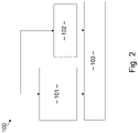
- the method 100 comprises a condenser cooling step 101 that is performed partly simultaneous to a product cooling step 102. After completion of the condenser cooling step 101 and the product cooling step 102, the freeze dryer 1 performs a freeze-drying step 103. Those steps will be elucidated in detail below.
- the condenser cooling step 101 heat is transferred from the condenser cooling circuit 20 to the first additional cooling circuit 30 comprising carbon dioxide or ammonia as refrigerant via the first heat exchanger 51.
- the temperature of the condenser 4 will decrease. If the temperature of the condenser 3 or the second heat transfer fluid of the condenser cooling circuit 20 is higher than a predetermined threshold temperature the air cycle cooling system 25 will stay inactive. In this phase, the condenser cooling circuit 20 is only cooled by the first additional cooling circuit 30.
- the predetermined threshold temperature is in the range from -20 °C to -40°C, for example -20 °C. If the temperature of the condenser 3 or the second heat transfer fluid of the condenser cooling circuit 20 falls below the predetermined threshold temperature, the air cycle cooling system 25 is activated so that additional cooling capacity is provided by the air cycle cooling system 25.
- cooling of the product chamber 2 is started in a product cooling step 102.
- products may be put into the product chamber 2, in particular into the shelf 3 of the product chamber 2.
- the valve 24 of the condenser cooling circuit 20 is adjusted so that the third heat exchanger 53 transfers heat from the product cooling circuit 10 to the condenser cooling circuit 20.
- Temperature of the shelf 3 and the products contained therein may be regulated by adjusting the valve 24 of the condenser cooling circuit 20.
- heat is transferred from the product chamber cooling circuit 10 to the second additional cooling circuit 30' via a fourth heat exchanger 54.
- the operation of the fourth heat exchanger 54 can be activated by opening the valve 32 of the second additional cooling circuit 30', preferably if the temperature of the shelf 3 or the temperature of the first heat transfer fluid of the product chamber cooling circuit 10 is within a predetermined region, e.g. between -40 °C and -51°C.
- the second additional cooling circuit 30' optionally comprises a secondary valve 35, that can be implemented as a check valve or shut-off valve.
- the secondary valve 35 may be implemented in addition to the primary valve 32 in order to enable operating the fourth heat exchanger 54 in a state where the part of the first heat exchanger 51 that is connected to the second additional cooling circuit 30' is dried out.
- the primary valve 32 can be set to a fully closed position and refrigerant can be sucked out of the fourth heat exchanger 54.
- the secondary valve 35 is implemented as a check-vale undesired re-flow of refrigerant into the fourth heat exchanger 54 can be avoided.
- the secondary valve 35 is implemented as a shut-off valve the secondary valve 35 can be set to a fully closed position after refrigerant has been removed from the fourth heat exchanger 54.
- the temperature of the condenser 4 is at least 5 °C below the temperature in the product chamber 2.
- the gas passage closure is opened so that the gas passage 6 is open.
- the pressure inside the product chamber 2 is reduced by a vacuum pump.
- the third heat exchanger 53 is decoupled from a flow of second heat transfer fluid in the condenser cooling circuit 20 so as to reduce heat transfer from the product chamber cooling circuit 10 to the condenser cooling circuit 20 and the first heat transfer fluid of the product chamber cooling circuit 10 is heated by the heaters 12 of the product chamber cooling circuit 10.
- the air cycle cooling system 25 cools the condenser cooling circuit to the lowest possible temperature depending on the vapour load.
- Vapour is drawn off the product chamber 2 and condenses on the condenser coils 5 or condenser plates of the condenser 4.
- the first heat exchanger 51 is decoupled from a flow of refrigerant in the first additional cooling circuit 30 so as to reduce heat transfer from the condenser cooling circuit 20 to the first additional cooling circuit 30.
- the temperature in the product chamber 2 and in the condenser 4 is increased.
- the products are unloaded from the product chamber.
- a self-cleaning procedure or self-sterilising procedure may succeed.
- the condenser 4 and the condenser cooling circuit 20 are heated up to a given sterilization temperature, e.g. above 121,1 °C.
- the first heat exchanger may be activated again so as to cool the condenser cooling circuit 20 using the additional cooling circuit 30 in order to prepare the freeze dryer 1 for the next batch of products to be freeze-dried.
Landscapes
- Engineering & Computer Science (AREA)
- Mechanical Engineering (AREA)
- General Engineering & Computer Science (AREA)
- Physics & Mathematics (AREA)
- Thermal Sciences (AREA)
- Health & Medical Sciences (AREA)
- Life Sciences & Earth Sciences (AREA)
- Molecular Biology (AREA)
- Chemical & Material Sciences (AREA)
- Chemical Kinetics & Catalysis (AREA)
- Drying Of Solid Materials (AREA)
Priority Applications (7)
| Application Number | Priority Date | Filing Date | Title |
|---|---|---|---|
| EP21160974.8A EP4053481A1 (fr) | 2021-03-05 | 2021-03-05 | Lyophilisateur et procédé pour faire fonctionner un lyophilisateur |
| EP22709317.6A EP4302033A1 (fr) | 2021-03-05 | 2022-03-02 | Lyophilisateur et procédé de fonctionnement d'un lyophilisateur |
| PCT/EP2022/055260 WO2022184767A1 (fr) | 2021-03-05 | 2022-03-02 | Lyophilisateur et procédé de fonctionnement d'un lyophilisateur |
| AU2022231364A AU2022231364A1 (en) | 2021-03-05 | 2022-03-02 | A freeze dryer and a method for operating a freeze dryer |
| US18/279,629 US20240142172A1 (en) | 2021-03-05 | 2022-03-02 | A Freeze Dryer and a Method for Operating a Freeze Dryer |
| CA3211033A CA3211033A1 (fr) | 2021-03-05 | 2022-03-02 | Lyophilisateur et procede de fonctionnement d'un lyophilisateur |
| CN202280017541.8A CN117178156A (zh) | 2021-03-05 | 2022-03-02 | 冻干机和用于操作冻干机的方法 |
Applications Claiming Priority (1)
| Application Number | Priority Date | Filing Date | Title |
|---|---|---|---|
| EP21160974.8A EP4053481A1 (fr) | 2021-03-05 | 2021-03-05 | Lyophilisateur et procédé pour faire fonctionner un lyophilisateur |
Publications (1)
| Publication Number | Publication Date |
|---|---|
| EP4053481A1 true EP4053481A1 (fr) | 2022-09-07 |
Family
ID=74859312
Family Applications (2)
| Application Number | Title | Priority Date | Filing Date |
|---|---|---|---|
| EP21160974.8A Withdrawn EP4053481A1 (fr) | 2021-03-05 | 2021-03-05 | Lyophilisateur et procédé pour faire fonctionner un lyophilisateur |
| EP22709317.6A Pending EP4302033A1 (fr) | 2021-03-05 | 2022-03-02 | Lyophilisateur et procédé de fonctionnement d'un lyophilisateur |
Family Applications After (1)
| Application Number | Title | Priority Date | Filing Date |
|---|---|---|---|
| EP22709317.6A Pending EP4302033A1 (fr) | 2021-03-05 | 2022-03-02 | Lyophilisateur et procédé de fonctionnement d'un lyophilisateur |
Country Status (6)
| Country | Link |
|---|---|
| US (1) | US20240142172A1 (fr) |
| EP (2) | EP4053481A1 (fr) |
| CN (1) | CN117178156A (fr) |
| AU (1) | AU2022231364A1 (fr) |
| CA (1) | CA3211033A1 (fr) |
| WO (1) | WO2022184767A1 (fr) |
Cited By (1)
| Publication number | Priority date | Publication date | Assignee | Title |
|---|---|---|---|---|
| WO2025181265A1 (fr) * | 2024-03-01 | 2025-09-04 | Gea Lyophil Gmbh | Procédé de contrôle d'un processus de lyophilisation et appareil de lyophilisation approprié correspondant |
Families Citing this family (2)
| Publication number | Priority date | Publication date | Assignee | Title |
|---|---|---|---|---|
| US20240369296A1 (en) * | 2021-04-16 | 2024-11-07 | Ima Life North America Inc. | Cooling system for freeze dryer |
| CN120361796B (zh) * | 2025-06-13 | 2025-10-03 | 中交上海航道勘察设计研究院有限公司 | 一种水凝胶颗粒成套生产设备及生产方法 |
Citations (9)
| Publication number | Priority date | Publication date | Assignee | Title |
|---|---|---|---|---|
| US2453033A (en) * | 1945-03-08 | 1948-11-02 | York Corp | Vacuum drying apparatus using a refrigerant system for heating and cooling |
| US3376652A (en) * | 1966-06-17 | 1968-04-09 | Luis A. Hernandez Jr. | Low temperature freeze drying process and apparatus therefor |
| US4407140A (en) * | 1979-07-04 | 1983-10-04 | Kyowa Vacuum Engineering, Ltd. | Vacuum apparatus |
| US6311510B1 (en) * | 1999-04-28 | 2001-11-06 | Kyowa Vacuum Engineering, Ltd. | Vapor condenser with high efficiency for use in vacuum apparatus |
| JP2010054064A (ja) * | 2008-08-26 | 2010-03-11 | Kyowa Shinku Gijutsu Kk | 凍結乾燥方法及び凍結乾燥装置 |
| JP2010144966A (ja) * | 2008-12-17 | 2010-07-01 | Kyowa Shinku Gijutsu Kk | 凍結乾燥装置 |
| CN203928604U (zh) * | 2014-04-29 | 2014-11-05 | 上虞冠峰食品机械有限公司 | 一种新型食品真空冷冻干燥机 |
| CN104534729A (zh) * | 2014-06-13 | 2015-04-22 | 楚天科技股份有限公司 | 一种冻干机制冷系统及该制冷系统的控制方法 |
| CN109140909A (zh) * | 2018-08-16 | 2019-01-04 | 楚天科技股份有限公司 | 冻干机板层温度控制方法及系统 |
Family Cites Families (3)
| Publication number | Priority date | Publication date | Assignee | Title |
|---|---|---|---|---|
| NL6908334A (fr) * | 1969-05-30 | 1970-12-02 | ||
| CN2695888Y (zh) * | 2004-04-29 | 2005-04-27 | 上海远东制药机械总厂 | 一种真空冷冻干燥机 |
| US20110265506A1 (en) * | 2010-05-01 | 2011-11-03 | Gerald Allen Alston | High Ratio Mobile Electric HVAC System |
-
2021
- 2021-03-05 EP EP21160974.8A patent/EP4053481A1/fr not_active Withdrawn
-
2022
- 2022-03-02 AU AU2022231364A patent/AU2022231364A1/en active Pending
- 2022-03-02 CA CA3211033A patent/CA3211033A1/fr active Pending
- 2022-03-02 EP EP22709317.6A patent/EP4302033A1/fr active Pending
- 2022-03-02 US US18/279,629 patent/US20240142172A1/en active Pending
- 2022-03-02 WO PCT/EP2022/055260 patent/WO2022184767A1/fr not_active Ceased
- 2022-03-02 CN CN202280017541.8A patent/CN117178156A/zh active Pending
Patent Citations (9)
| Publication number | Priority date | Publication date | Assignee | Title |
|---|---|---|---|---|
| US2453033A (en) * | 1945-03-08 | 1948-11-02 | York Corp | Vacuum drying apparatus using a refrigerant system for heating and cooling |
| US3376652A (en) * | 1966-06-17 | 1968-04-09 | Luis A. Hernandez Jr. | Low temperature freeze drying process and apparatus therefor |
| US4407140A (en) * | 1979-07-04 | 1983-10-04 | Kyowa Vacuum Engineering, Ltd. | Vacuum apparatus |
| US6311510B1 (en) * | 1999-04-28 | 2001-11-06 | Kyowa Vacuum Engineering, Ltd. | Vapor condenser with high efficiency for use in vacuum apparatus |
| JP2010054064A (ja) * | 2008-08-26 | 2010-03-11 | Kyowa Shinku Gijutsu Kk | 凍結乾燥方法及び凍結乾燥装置 |
| JP2010144966A (ja) * | 2008-12-17 | 2010-07-01 | Kyowa Shinku Gijutsu Kk | 凍結乾燥装置 |
| CN203928604U (zh) * | 2014-04-29 | 2014-11-05 | 上虞冠峰食品机械有限公司 | 一种新型食品真空冷冻干燥机 |
| CN104534729A (zh) * | 2014-06-13 | 2015-04-22 | 楚天科技股份有限公司 | 一种冻干机制冷系统及该制冷系统的控制方法 |
| CN109140909A (zh) * | 2018-08-16 | 2019-01-04 | 楚天科技股份有限公司 | 冻干机板层温度控制方法及系统 |
Cited By (1)
| Publication number | Priority date | Publication date | Assignee | Title |
|---|---|---|---|---|
| WO2025181265A1 (fr) * | 2024-03-01 | 2025-09-04 | Gea Lyophil Gmbh | Procédé de contrôle d'un processus de lyophilisation et appareil de lyophilisation approprié correspondant |
Also Published As
| Publication number | Publication date |
|---|---|
| WO2022184767A1 (fr) | 2022-09-09 |
| AU2022231364A1 (en) | 2023-08-17 |
| CA3211033A1 (fr) | 2022-09-09 |
| CN117178156A (zh) | 2023-12-05 |
| US20240142172A1 (en) | 2024-05-02 |
| EP4302033A1 (fr) | 2024-01-10 |
Similar Documents
| Publication | Publication Date | Title |
|---|---|---|
| US20240142172A1 (en) | A Freeze Dryer and a Method for Operating a Freeze Dryer | |
| DK2417406T3 (en) | Coolant vapor compression system with hot gas bypass | |
| DK2504641T3 (en) | PROTECTION FROM LOW SUCTION PRESSURE IN COOLING STEAM COMPRESSION SYSTEM | |
| DK2147264T3 (en) | Refrigerant vapor compression system | |
| US10690410B2 (en) | Freeze-drying system and freeze-drying method | |
| KR20200021466A (ko) | 냉동 시스템 및 방법 | |
| EP3425306B1 (fr) | Dispositif de congélation | |
| US2453033A (en) | Vacuum drying apparatus using a refrigerant system for heating and cooling | |
| JP2012504221A (ja) | プルダウン時における容量の増加 | |
| KR20200013868A (ko) | 열저장을 이용하는 진공동결건조시스템 | |
| US20200191446A1 (en) | Mechanical subcooling of transcritical r744 refrigeration systems using separate r-744 or other refrigerants units for mechanical subcooling and as a heat pump for heat reclaim purposes | |
| CA3027892C (fr) | Systeme de refrigeration r-744 transcritique destine aux supermarches offrant une efficacite et une fiabilite ameliorees | |
| KR20240026226A (ko) | 직렬로 배치되는 순환형 극저온 냉각기 시스템 | |
| US11754320B2 (en) | Refrigeration system with multiple heat absorbing heat exchangers | |
| KR20200031359A (ko) | 냉동탑차의 적재함 냉각 시스템 | |
| JP2001194025A (ja) | 蒸気エジェクタによるガスエンジンの排熱利用方法とその装置 | |
| US20240369296A1 (en) | Cooling system for freeze dryer | |
| CN117295922B (zh) | 用于冷冻干燥机的冷却系统 | |
| KR102720952B1 (ko) | 복합 냉동기 | |
| US20250362060A1 (en) | Water chiller thermal storage | |
| US20260023038A1 (en) | Test Chamber and Control Method | |
| CN115289707B (zh) | 一种空气制冷系统及其应用 | |
| WO2018074272A1 (fr) | Dispositif de réfrigération | |
| CN118293646A (zh) | 一种冻干机及冻干方法 | |
| CN105937811B (zh) | 冷冻装置 |
Legal Events
| Date | Code | Title | Description |
|---|---|---|---|
| PUAI | Public reference made under article 153(3) epc to a published international application that has entered the european phase |
Free format text: ORIGINAL CODE: 0009012 |
|
| STAA | Information on the status of an ep patent application or granted ep patent |
Free format text: STATUS: THE APPLICATION HAS BEEN PUBLISHED |
|
| AK | Designated contracting states |
Kind code of ref document: A1 Designated state(s): AL AT BE BG CH CY CZ DE DK EE ES FI FR GB GR HR HU IE IS IT LI LT LU LV MC MK MT NL NO PL PT RO RS SE SI SK SM TR |
|
| STAA | Information on the status of an ep patent application or granted ep patent |
Free format text: STATUS: THE APPLICATION IS DEEMED TO BE WITHDRAWN |
|
| 18D | Application deemed to be withdrawn |
Effective date: 20230308 |