EP4053553A1 - Verfahren zur erkennung von rissen in einem durch additive fertigung hergestellten teil aus aluminiumlegierung - Google Patents
Verfahren zur erkennung von rissen in einem durch additive fertigung hergestellten teil aus aluminiumlegierung Download PDFInfo
- Publication number
- EP4053553A1 EP4053553A1 EP22159614.1A EP22159614A EP4053553A1 EP 4053553 A1 EP4053553 A1 EP 4053553A1 EP 22159614 A EP22159614 A EP 22159614A EP 4053553 A1 EP4053553 A1 EP 4053553A1
- Authority
- EP
- European Patent Office
- Prior art keywords
- receiver
- additive manufacturing
- aluminum alloy
- transmitter
- quality factor
- Prior art date
- Legal status (The legal status is an assumption and is not a legal conclusion. Google has not performed a legal analysis and makes no representation as to the accuracy of the status listed.)
- Pending
Links
Images


Classifications
-
- G—PHYSICS
- G01—MEASURING; TESTING
- G01N—INVESTIGATING OR ANALYSING MATERIALS BY DETERMINING THEIR CHEMICAL OR PHYSICAL PROPERTIES
- G01N29/00—Investigating or analysing materials by the use of ultrasonic, sonic or infrasonic waves; Visualisation of the interior of objects by transmitting ultrasonic or sonic waves through the object
- G01N29/44—Processing the detected response signal, e.g. electronic circuits specially adapted therefor
- G01N29/46—Processing the detected response signal, e.g. electronic circuits specially adapted therefor by spectral analysis, e.g. Fourier analysis or wavelet analysis
-
- B—PERFORMING OPERATIONS; TRANSPORTING
- B33—ADDITIVE MANUFACTURING TECHNOLOGY
- B33Y—ADDITIVE MANUFACTURING, i.e. MANUFACTURING OF THREE-DIMENSIONAL [3D] OBJECTS BY ADDITIVE DEPOSITION, ADDITIVE AGGLOMERATION OR ADDITIVE LAYERING, e.g. BY 3D PRINTING, STEREOLITHOGRAPHY OR SELECTIVE LASER SINTERING
- B33Y10/00—Processes of additive manufacturing
-
- B—PERFORMING OPERATIONS; TRANSPORTING
- B33—ADDITIVE MANUFACTURING TECHNOLOGY
- B33Y—ADDITIVE MANUFACTURING, i.e. MANUFACTURING OF THREE-DIMENSIONAL [3D] OBJECTS BY ADDITIVE DEPOSITION, ADDITIVE AGGLOMERATION OR ADDITIVE LAYERING, e.g. BY 3D PRINTING, STEREOLITHOGRAPHY OR SELECTIVE LASER SINTERING
- B33Y99/00—Subject matter not provided for in other groups of this subclass
-
- G—PHYSICS
- G01—MEASURING; TESTING
- G01H—MEASUREMENT OF MECHANICAL VIBRATIONS OR ULTRASONIC, SONIC OR INFRASONIC WAVES
- G01H1/00—Measuring characteristics of vibrations in solids by using direct conduction to the detector
-
- G—PHYSICS
- G01—MEASURING; TESTING
- G01H—MEASUREMENT OF MECHANICAL VIBRATIONS OR ULTRASONIC, SONIC OR INFRASONIC WAVES
- G01H3/00—Measuring characteristics of vibrations by using a detector in a fluid
- G01H3/04—Frequency
- G01H3/06—Frequency by electric means
-
- G—PHYSICS
- G01—MEASURING; TESTING
- G01N—INVESTIGATING OR ANALYSING MATERIALS BY DETERMINING THEIR CHEMICAL OR PHYSICAL PROPERTIES
- G01N29/00—Investigating or analysing materials by the use of ultrasonic, sonic or infrasonic waves; Visualisation of the interior of objects by transmitting ultrasonic or sonic waves through the object
- G01N29/04—Analysing solids
- G01N29/12—Analysing solids by measuring frequency or resonance of acoustic waves
-
- G—PHYSICS
- G01—MEASURING; TESTING
- G01N—INVESTIGATING OR ANALYSING MATERIALS BY DETERMINING THEIR CHEMICAL OR PHYSICAL PROPERTIES
- G01N29/00—Investigating or analysing materials by the use of ultrasonic, sonic or infrasonic waves; Visualisation of the interior of objects by transmitting ultrasonic or sonic waves through the object
- G01N29/44—Processing the detected response signal, e.g. electronic circuits specially adapted therefor
- G01N29/4409—Processing the detected response signal, e.g. electronic circuits specially adapted therefor by comparison
- G01N29/4427—Processing the detected response signal, e.g. electronic circuits specially adapted therefor by comparison with stored values, e.g. threshold values
-
- B—PERFORMING OPERATIONS; TRANSPORTING
- B22—CASTING; POWDER METALLURGY
- B22F—WORKING METALLIC POWDER; MANUFACTURE OF ARTICLES FROM METALLIC POWDER; MAKING METALLIC POWDER; APPARATUS OR DEVICES SPECIALLY ADAPTED FOR METALLIC POWDER
- B22F10/00—Additive manufacturing of workpieces or articles from metallic powder
- B22F10/20—Direct sintering or melting
- B22F10/28—Powder bed fusion, e.g. selective laser melting [SLM] or electron beam melting [EBM]
-
- B—PERFORMING OPERATIONS; TRANSPORTING
- B22—CASTING; POWDER METALLURGY
- B22F—WORKING METALLIC POWDER; MANUFACTURE OF ARTICLES FROM METALLIC POWDER; MAKING METALLIC POWDER; APPARATUS OR DEVICES SPECIALLY ADAPTED FOR METALLIC POWDER
- B22F2999/00—Aspects linked to processes or compositions used in powder metallurgy
-
- B—PERFORMING OPERATIONS; TRANSPORTING
- B33—ADDITIVE MANUFACTURING TECHNOLOGY
- B33Y—ADDITIVE MANUFACTURING, i.e. MANUFACTURING OF THREE-DIMENSIONAL [3D] OBJECTS BY ADDITIVE DEPOSITION, ADDITIVE AGGLOMERATION OR ADDITIVE LAYERING, e.g. BY 3D PRINTING, STEREOLITHOGRAPHY OR SELECTIVE LASER SINTERING
- B33Y80/00—Products made by additive manufacturing
-
- G—PHYSICS
- G01—MEASURING; TESTING
- G01N—INVESTIGATING OR ANALYSING MATERIALS BY DETERMINING THEIR CHEMICAL OR PHYSICAL PROPERTIES
- G01N2291/00—Indexing codes associated with group G01N29/00
- G01N2291/02—Indexing codes associated with the analysed material
- G01N2291/023—Solids
- G01N2291/0234—Metals, e.g. steel
-
- G—PHYSICS
- G01—MEASURING; TESTING
- G01N—INVESTIGATING OR ANALYSING MATERIALS BY DETERMINING THEIR CHEMICAL OR PHYSICAL PROPERTIES
- G01N2291/00—Indexing codes associated with group G01N29/00
- G01N2291/02—Indexing codes associated with the analysed material
- G01N2291/028—Material parameters
- G01N2291/0289—Internal structure, e.g. defects, grain size, texture
-
- G—PHYSICS
- G01—MEASURING; TESTING
- G01N—INVESTIGATING OR ANALYSING MATERIALS BY DETERMINING THEIR CHEMICAL OR PHYSICAL PROPERTIES
- G01N2291/00—Indexing codes associated with group G01N29/00
- G01N2291/04—Wave modes and trajectories
- G01N2291/048—Transmission, i.e. analysed material between transmitter and receiver
-
- G—PHYSICS
- G01—MEASURING; TESTING
- G01N—INVESTIGATING OR ANALYSING MATERIALS BY DETERMINING THEIR CHEMICAL OR PHYSICAL PROPERTIES
- G01N2291/00—Indexing codes associated with group G01N29/00
- G01N2291/10—Number of transducers
- G01N2291/102—Number of transducers one emitter, one receiver
Definitions
- the present invention relates to the general field of non-destructive testing (NDT) of parts, in particular those produced by an additive manufacturing technique.
- the method according to the invention is particularly intended to be implemented for aluminum alloy parts manufactured by additive manufacturing technique implementing preferably complete melting of the powder by means of laser radiation or by means of an electron beam.
- Aluminum alloy additive manufacturing is today at a much less advanced stage of development than other materials, such as polymers, titanium alloys or nickel bases.
- the method a priori the most obvious and the simplest to measure the density of a part, and in particular to check whether or not it is cracked consists in carrying out one or more metallographic cuts in the part: [1]. With proper polishing and etching, any cracks are easily revealed. However, this method is destructive and local.
- Helium pycnometry can also measure the absolute density of a part. This method is probably more accurate, but it is limited to the characterization of small volume parts. Moreover, the knowledge of the density does not make it possible to detect the presence of internal cracks in all the cases.
- US waves ultrasonic waves
- a known result from the state of the art is that US waves are diffracted on structural defects (grain boundaries, cracks, etc.) of the material, which results in more noisy ultrasonic signals than on non-defective materials, even presenting echoes linked to the location of defects.
- a particularly interesting technique is ultrasonic resonance spectroscopy (RUS for “Resonant Ultrasound Sprectroscopy” in English terminology).
- RUS ultrasonic resonance spectroscopy
- This RUS technique is based on the establishment of standing waves in the part to be tested and on the measurement of a certain number of frequencies or resonance peaks of said part. Used in connection with a numerical simulation of the equations of motion, for example by the finite element method, the technique allows a precise estimation of the elastic constants of materials [2].
- This RUS technique can also be used for defect characterization since, as mentioned above, any structural defect will influence wave propagation. More precisely, on the resonance peaks, the influence of the defects can result in displacements, splittings, widenings and amplitude variations. In axisymmetric samples of known geometry, defects can even be localized [2].
- Publication [3] addresses the problem of the effect of localized cracks of different lengths on the RUS resonance spectrum of silicon (Si) wafers. More particularly, the processing is focused on a particular peak, denoted A in the publication, which can be seen to shift and widen when the length of the crack increases.
- this publication [3] does not address the problem of evaluating the defective state of a part where many microscopic defects may be present, as opposed to a localized macroscopic defect. Furthermore, it assumes that the geometry of the part to be tested is known with precision.
- parts made of aluminum alloys produced by additive manufacturing may have numerous microcracks within them.
- Another characteristic of these parts is to have a very large number of crystallographic grains, which are generally associated with the extreme solidification conditions (very strong thermal gradients, very rapid growth rate) encountered in additive manufacturing processes.
- the width of grains observed is for the most part less than 30 ⁇ m.
- FIG 2 maps by backscattered electron diffraction (Anglo-Saxon acronym EBSD for “Electron Back Scattered Diffraction”): it shows the grain structure in an Al 6061 alloy produced by SLM. It is specified that the scale bar indicated on this optical micrograph represents a length of 200 ⁇ m.
- the general object of the invention is then to meet this need at least in part.
- the reference quality factor (Qref) preferably corresponds to an aluminum alloy part reputed to be of good quality, preferably without cracks.
- the invention essentially consists of an analysis of the ultrasonic resonance spectra (RUS) acquired on an aluminum alloy part produced by additive manufacturing.
- RUS ultrasonic resonance spectra
- the inventors were able, against all expectations, to observe that in an analysis of the RUS signal the peaks/noise ratio appears mainly linked to the cracks and that the analysis of the spectra according to the invention based on the value of the quality factor of at least one of the peaks of the resonance spectrum allows unambiguous identification of cracked parts independently of the structure of the grains in the analyzed part.
- the method according to the invention is not concerned with the offset of resonance peaks with respect to a healthy reference state.
- step d/ consists of determining the peak of the fundamental resonant frequency of the part.
- step d/ consists of determining at least 10 resonance peaks by frequency scanning.
- the reference quality factor (Qref) is at least equal to 800, preferably at least equal to 1000.
- step d/ is carried out by a thresholding algorithm.
- step e/ consists of adjusting the at least one peak by means of a Lorentzian function.
- step b/ is repeated so as to determine at least two, preferably at least three, even more preferably at least five spectra according to step d/.
- the fact of making several acquisitions (recordings) makes it possible to detect any missing resonance frequencies and to verify that this number of missing frequencies is low.
- the method comprises, before step e/, a step d1/ of merging the at least two spectra determined by masking. In case a missing frequency has been identified, by combining at least two records and merging them by masking.
- the invention also relates to a computer program product for implementing the detection method mentioned above.
- the subject of the invention is a method for the non-destructive testing (NDT) of an aluminum alloy part produced by an additive manufacturing technique, comprising a step of measuring the density of the part by a technique for measuring the Archimedean thrust before or after carrying out the detection method mentioned above.
- NDT non-destructive testing
- the invention can be envisaged for all applications and industrial fields implementing aluminum alloys, in particular in the aeronautics and automobile sectors. More particularly, it is possible to envisage the non-destructive testing of reactor exchangers produced by additive manufacturing by means of a method according to the invention.
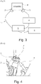
- the picture 3 shows a crack detection system 1 implemented according to the invention.
- System 1 comprises an ultrasound transmitter 2 and an ultrasound receiver 3. These sensors are preferably piezoelectric.
- the transmitter 2 and the receiver 3 are in direct contact with an aluminum alloy part P produced by additive manufacturing to be analyzed.
- the transmitter 2 and the receiver 3 are each in direct contact with a corner of the part P.
- one or more point supports A can be envisaged to facilitate the measurement of the signals.
- An amplifier 4 is connected to the receiver 3.
- a spectrum analyzer 5 is connected both to transmitter 2 and optionally to amplifier 4 or otherwise to receiver 3.
- an electronic processing unit 6 for example integrated into a laptop computer, is connected to the spectrum analyzer 5.
- Spectrum analyzer 5 makes it possible to measure the transmission-reception signal transfer function.
- the transfer function presents a series of peaks which are characteristic of the proper modes of vibration of the part P, depending on its geometry, its elasticity, its internal defects
- the adjustment of the spectrum analyzer is advantageously made according to the orders magnitude of the known resonance frequencies of the part P in order to observe at least one resonance frequency.
- the processing of the signals carried out by the processing unit from the spectrum analyzer is as follows.
- An extraction of resonance peaks is carried out on the signal previously subjected to a thresholding algorithm. It may for example involve thresholding from portions of the signal above a certain amplitude level, typically using the “find_peaks” function: see for example [5], [6].
- the figure 5 shows the spectrum obtained after peak extraction (vertical bars on the graph), the figure 6 shows the quality factors Q adjusted over the frequency range and the figure 7 shows the amplitude of the peaks.
- Q quality factors take on values between 200 and 700, which are indicative of a cracked specimen for the aluminum alloy material being evaluated.
- the inventors carried out various tests with samples of A1 6061 and 7075 alloys.
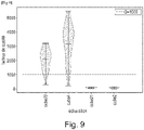
- quality factors Q lower than a reference value Q ref of 800 are indicative of cracked samples, while quality factors Q higher than this value, in median, indicate samples without the presence of crack.
- the figure 9 reports this observation showing the distribution of quality factors for four samples in the form of Al 6061 alloy cubes, two of which are free of cracks and the other two have cracks.
- the calculated median of the quality factors Q for each cube is indicated by the horizontal bar in the center of the “violin” shaped curves.
- the median of the quality factors obtained is greater than the reference value equal to 1000 for the cubes 22 and 4 is less than this value for the cubes 21 and 2. And therefore, according to the method of the invention, the cubes referenced 22 and 4 are without cracks, while cubes 21 and 2 are cracked, which has been verified experimentally by metallography. It is also interesting to point out that the cube 22 is not dense in the sense of the measurement by Archimedes' thrust, with a relative density of the order of 97%, which confirms the absence of correlation between the values of the quality and density factors.
- the method according to the invention is a complementary method to the density measurement, since a good part must be both dense and free of cracks.
- cube 22 is free of cracks but must be rejected because of its poor density, while cube 21 must be rejected despite its good density because it has many cracks.
- the contacting of the emitter-receiver is carried out on the corners of the part to be analyzed, one can also consider other locations, or even add point supports A as shown. in figure 4 to facilitate the measurement.
Landscapes
- Physics & Mathematics (AREA)
- Chemical & Material Sciences (AREA)
- Engineering & Computer Science (AREA)
- General Physics & Mathematics (AREA)
- Immunology (AREA)
- Signal Processing (AREA)
- Life Sciences & Earth Sciences (AREA)
- Pathology (AREA)
- Analytical Chemistry (AREA)
- Biochemistry (AREA)
- General Health & Medical Sciences (AREA)
- Health & Medical Sciences (AREA)
- Manufacturing & Machinery (AREA)
- Materials Engineering (AREA)
- Mathematical Physics (AREA)
- Spectroscopy & Molecular Physics (AREA)
- Acoustics & Sound (AREA)
- Investigating Or Analyzing Materials By The Use Of Ultrasonic Waves (AREA)
Applications Claiming Priority (1)
| Application Number | Priority Date | Filing Date | Title |
|---|---|---|---|
| FR2102040A FR3120444B1 (fr) | 2021-03-03 | 2021-03-03 | Procédé de détection de fissures dans une pièce en alliage d’aluminium réalisée par fabrication additive. |
Publications (1)
| Publication Number | Publication Date |
|---|---|
| EP4053553A1 true EP4053553A1 (de) | 2022-09-07 |
Family
ID=76601273
Family Applications (1)
| Application Number | Title | Priority Date | Filing Date |
|---|---|---|---|
| EP22159614.1A Pending EP4053553A1 (de) | 2021-03-03 | 2022-03-02 | Verfahren zur erkennung von rissen in einem durch additive fertigung hergestellten teil aus aluminiumlegierung |
Country Status (2)
| Country | Link |
|---|---|
| EP (1) | EP4053553A1 (de) |
| FR (1) | FR3120444B1 (de) |
Citations (8)
| Publication number | Priority date | Publication date | Assignee | Title |
|---|---|---|---|---|
| US5257544A (en) * | 1992-01-22 | 1993-11-02 | The Board Of Trustees Of The Leland Stanford Junior University | Resonant frequency method for bearing ball inspection |
| US5942991A (en) * | 1995-06-06 | 1999-08-24 | Diversified Technologies, Inc. | Resonant sensor system and method |
| US20090188320A1 (en) * | 2006-07-31 | 2009-07-30 | Rodney David Greenough | Method of and apparatus for testing wooden poles |
| US20140102200A1 (en) * | 2012-10-16 | 2014-04-17 | Honeywell International Inc. | Methods for non-destructively evaluating a joined component |
| US20150300993A1 (en) * | 2012-04-24 | 2015-10-22 | Christopher D. Prest | Ultrasonic inspection |
| US20200108594A1 (en) * | 2014-04-10 | 2020-04-09 | United Technologies Corporation | Real-time resonant inspection for additive manufacturing |
| CN111024819A (zh) * | 2019-12-23 | 2020-04-17 | 复旦大学 | 一种珠宝与首饰声共振谱仿伪方法 |
| US20200324483A1 (en) * | 2019-04-11 | 2020-10-15 | Southern Research Institute | In-Situ Monitoring of Additive Manufacturing Layer-by-Layer Build Using Ultrasonic Spectroscopy |
-
2021
- 2021-03-03 FR FR2102040A patent/FR3120444B1/fr active Active
-
2022
- 2022-03-02 EP EP22159614.1A patent/EP4053553A1/de active Pending
Patent Citations (8)
| Publication number | Priority date | Publication date | Assignee | Title |
|---|---|---|---|---|
| US5257544A (en) * | 1992-01-22 | 1993-11-02 | The Board Of Trustees Of The Leland Stanford Junior University | Resonant frequency method for bearing ball inspection |
| US5942991A (en) * | 1995-06-06 | 1999-08-24 | Diversified Technologies, Inc. | Resonant sensor system and method |
| US20090188320A1 (en) * | 2006-07-31 | 2009-07-30 | Rodney David Greenough | Method of and apparatus for testing wooden poles |
| US20150300993A1 (en) * | 2012-04-24 | 2015-10-22 | Christopher D. Prest | Ultrasonic inspection |
| US20140102200A1 (en) * | 2012-10-16 | 2014-04-17 | Honeywell International Inc. | Methods for non-destructively evaluating a joined component |
| US20200108594A1 (en) * | 2014-04-10 | 2020-04-09 | United Technologies Corporation | Real-time resonant inspection for additive manufacturing |
| US20200324483A1 (en) * | 2019-04-11 | 2020-10-15 | Southern Research Institute | In-Situ Monitoring of Additive Manufacturing Layer-by-Layer Build Using Ultrasonic Spectroscopy |
| CN111024819A (zh) * | 2019-12-23 | 2020-04-17 | 复旦大学 | 一种珠宝与首饰声共振谱仿伪方法 |
Non-Patent Citations (7)
| Title |
|---|
| A. BELYAEVO. POLUPANW. DALLASS. OSTAPENKOD. HESSJ. WOHLGEMUTH: "Crack detection and analyses using resonance ultrasonic vibrations in full-size crystalline silicon wafers", APPL. PHYS. LETT., vol. 88, 2006, pages 111907, XP012080565, DOI: 10.1063/1.2186393 |
| A.B. SPIERINGS ET AL: "Comparison of density measurement techniques for additive manufactured metallic parts", RAPID PROTOTYPING JOURNAL, vol. 17, no. 5, 2 August 2011 (2011-08-02), GB, pages 380 - 386, XP055495225, ISSN: 1355-2546, DOI: 10.1108/13552541111156504 * |
| A.B. SPIERINGSM. SCHNEIDERR. EGGENBERGER: "Comparison of density measurement techniques for additive manufactured metallic parts", RAPID PROTOTYPING JOURNAL, vol. 17, no. 5, 2011, pages 380 - 386, XP055495225, DOI: 10.1108/13552541111156504 |
| HERNÁNDEZ-BECERRA P A I ET AL: "Comparison of Time-Domain and Frequency-Domain Contact Resonant Ultrasound Spectroscopy", INSTRUMENTS AND EXPERIMENTAL TECHNIQUES, CONSULTANTS BUREAU. NEW YORK, US, vol. 62, no. 2, 6 May 2019 (2019-05-06), pages 241 - 246, XP036775101, ISSN: 0020-4412, [retrieved on 20190506], DOI: 10.1134/S0020441219020118 * |
| K. FLYNNM. RADOVIC: "Evaluation of defects in materials using resonant ultrasound spectroscopy", J. MATER. SCI., vol. 46, 2011, pages 2548 - 2556, XP019876933, DOI: 10.1007/s10853-010-5107-y |
| M. OPPRECHTJ.P. GARANDETG. ROUXC. FLAMENTM. SOULIER: "A solution to the hot cracking problem for aluminium alloys manufactured by laser beam melting", ACTA MATERIALIA, vol. 197, 2020, pages 40 - 5 |
| P. DUW. KIBBES. LIN, IMPROVED PEAK DETECTION IN MASS SPECTRUM BY INCORPORATING CONTINUOUS WAVELET TRANSFORM-BASED PATTERN MATCHING, vol. 22, no. 17, 2006, pages 2059 - 2065 |
Also Published As
| Publication number | Publication date |
|---|---|
| FR3120444B1 (fr) | 2025-10-24 |
| FR3120444A1 (fr) | 2022-09-09 |
Similar Documents
| Publication | Publication Date | Title |
|---|---|---|
| EP0904535B1 (de) | Verfahren und vorrichtung zur erfassung und lokalisierung einer reflektierenden schallquelle | |
| EP3707503B1 (de) | Überwachung der strukturellen gesundheit für eine industriestruktur | |
| EP3847450B1 (de) | Verfahren zur ultraschalldetektion und charakterisierung von defekten in einem heterogenen material | |
| FR2854954A1 (fr) | Imagerie de defaut absolue a haute capacite | |
| EP4264253B1 (de) | Verfahren, vorrichtung und programm zur detektion von materialdefekten mittels ultraschall | |
| CA2968487A1 (fr) | Procede de detection et de caracterisation par ultrasons de defauts dans un materiau heterogene | |
| EP4200604B1 (de) | Verfahren zur charakterisierung eines teils durch zerstörungsfreie prüfung | |
| WO2024074252A1 (fr) | Procede d'imagerie ultrasonore par transformee de fourier multidimensionnelle a l'aide de deux transducteurs multielements distincts | |
| EP3532832B1 (de) | Verfahren zur zerstörungsfreien prüfung einer verklebten anordnung mittels ultraschall | |
| EP3769077B1 (de) | Verfahren und vorrichtung zur abbildung von komponenten zur detektion der dehnungsrichtung | |
| FR3027392A1 (fr) | Procede et ensemble de verification de la calibration d'un systeme de controle non destructif de pieces. | |
| EP3552008B1 (de) | Verfahren und vorrichtung zur prüfung einer verbindung zwischen zwei substraten | |
| FR3120444A1 (fr) | Procédé de détection de fissures dans une pièce en alliage d’aluminium réalisée par fabrication additive. | |
| EP3545295B1 (de) | Verfahren zum testen mit geführten wellen | |
| WO2021099727A1 (fr) | Procédé de détection de défaut par focalisation d'ondes ultrasonores générés par impulsion laser | |
| FR3140438A1 (fr) | Procédé d’optimisation bi-niveau de la localisation de capteurs de détection de défaut(s) dans une structure par tomographie à ondes élastiques guidées | |
| FR3140437A1 (fr) | Optimisation du placement d’un ensemble de capteurs de détection d’anomalie(s) dans une structure par tomographie à ondes guidées | |
| EP4300095B1 (de) | Verfahren zur automatischen identifizierung einer akustischen quelle aus einem erzeugten akustischen signal | |
| WO2025214998A1 (fr) | Procede de controle non destructif par ultrasons d'une barre metallique longitudinale | |
| CA3041166C (fr) | Procede de controle non destructif par ultrasons d'un assemblage colle | |
| FR3136858A1 (fr) | Procede de mesure de l’epaisseur et procede de mesure de la densite d’une eprouvette en materiau composite a matrice ceramique | |
| FR3136857A1 (fr) | Procede de mesure du module de rigidite axial d’une eprouvette en materiau composite a matrice ceramique | |
| EP4078165A1 (de) | Verfahren zum charakterisieren der inhaltlichkeit eines objekts, das einem mechanischen, thermischen oder thermoelastischen stress ausgesetzt ist, der in dem objekt elastische wellen erzeugen kann | |
| EP4217727A1 (de) | Kalibrierungsverfahren für an zylinderartige strukturen angepasste geführte elastische wellentomografie |
Legal Events
| Date | Code | Title | Description |
|---|---|---|---|
| PUAI | Public reference made under article 153(3) epc to a published international application that has entered the european phase |
Free format text: ORIGINAL CODE: 0009012 |
|
| STAA | Information on the status of an ep patent application or granted ep patent |
Free format text: STATUS: REQUEST FOR EXAMINATION WAS MADE |
|
| 17P | Request for examination filed |
Effective date: 20220302 |
|
| AK | Designated contracting states |
Kind code of ref document: A1 Designated state(s): AL AT BE BG CH CY CZ DE DK EE ES FI FR GB GR HR HU IE IS IT LI LT LU LV MC MK MT NL NO PL PT RO RS SE SI SK SM TR |
|
| STAA | Information on the status of an ep patent application or granted ep patent |
Free format text: STATUS: EXAMINATION IS IN PROGRESS |
|
| 17Q | First examination report despatched |
Effective date: 20240821 |
|
| RAP3 | Party data changed (applicant data changed or rights of an application transferred) |
Owner name: COMMISSARIAT A L'ENERGIE ATOMIQUE ET AUX ENERGIESALTERNATIVES |