EP4053682B1 - Benutzervorrichtungsbildschirm - Google Patents
Benutzervorrichtungsbildschirm Download PDFInfo
- Publication number
- EP4053682B1 EP4053682B1 EP21159818.0A EP21159818A EP4053682B1 EP 4053682 B1 EP4053682 B1 EP 4053682B1 EP 21159818 A EP21159818 A EP 21159818A EP 4053682 B1 EP4053682 B1 EP 4053682B1
- Authority
- EP
- European Patent Office
- Prior art keywords
- sources
- screen
- reflection
- potentially problematic
- determining
- Prior art date
- Legal status (The legal status is an assumption and is not a legal conclusion. Google has not performed a legal analysis and makes no representation as to the accuracy of the status listed.)
- Active
Links
Images


Classifications
-
- G—PHYSICS
- G06—COMPUTING OR CALCULATING; COUNTING
- G06F—ELECTRIC DIGITAL DATA PROCESSING
- G06F3/00—Input arrangements for transferring data to be processed into a form capable of being handled by the computer; Output arrangements for transferring data from processing unit to output unit, e.g. interface arrangements
- G06F3/01—Input arrangements or combined input and output arrangements for interaction between user and computer
- G06F3/03—Arrangements for converting the position or the displacement of a member into a coded form
- G06F3/041—Digitisers, e.g. for touch screens or touch pads, characterised by the transducing means
- G06F3/0416—Control or interface arrangements specially adapted for digitisers
- G06F3/0418—Control or interface arrangements specially adapted for digitisers for error correction or compensation, e.g. based on parallax, calibration or alignment
-
- G—PHYSICS
- G09—EDUCATION; CRYPTOGRAPHY; DISPLAY; ADVERTISING; SEALS
- G09G—ARRANGEMENTS OR CIRCUITS FOR CONTROL OF INDICATING DEVICES USING STATIC MEANS TO PRESENT VARIABLE INFORMATION
- G09G3/00—Control arrangements or circuits, of interest only in connection with visual indicators other than cathode-ray tubes
- G09G3/03—Control arrangements or circuits, of interest only in connection with visual indicators other than cathode-ray tubes specially adapted for displays having non-planar surfaces, e.g. curved displays
- G09G3/035—Control arrangements or circuits, of interest only in connection with visual indicators other than cathode-ray tubes specially adapted for displays having non-planar surfaces, e.g. curved displays for flexible display surfaces
-
- G—PHYSICS
- G06—COMPUTING OR CALCULATING; COUNTING
- G06F—ELECTRIC DIGITAL DATA PROCESSING
- G06F1/00—Details not covered by groups G06F3/00 - G06F13/00 and G06F21/00
- G06F1/16—Constructional details or arrangements
- G06F1/1613—Constructional details or arrangements for portable computers
- G06F1/1615—Constructional details or arrangements for portable computers with several enclosures having relative motions, each enclosure supporting at least one I/O or computing function
- G06F1/1616—Constructional details or arrangements for portable computers with several enclosures having relative motions, each enclosure supporting at least one I/O or computing function with folding flat displays, e.g. laptop computers or notebooks having a clamshell configuration, with body parts pivoting to an open position around an axis parallel to the plane they define in closed position
-
- G—PHYSICS
- G06—COMPUTING OR CALCULATING; COUNTING
- G06F—ELECTRIC DIGITAL DATA PROCESSING
- G06F3/00—Input arrangements for transferring data to be processed into a form capable of being handled by the computer; Output arrangements for transferring data from processing unit to output unit, e.g. interface arrangements
- G06F3/01—Input arrangements or combined input and output arrangements for interaction between user and computer
- G06F3/011—Arrangements for interaction with the human body, e.g. for user immersion in virtual reality
- G06F3/013—Eye tracking input arrangements
-
- G—PHYSICS
- G09—EDUCATION; CRYPTOGRAPHY; DISPLAY; ADVERTISING; SEALS
- G09G—ARRANGEMENTS OR CIRCUITS FOR CONTROL OF INDICATING DEVICES USING STATIC MEANS TO PRESENT VARIABLE INFORMATION
- G09G2340/00—Aspects of display data processing
- G09G2340/14—Solving problems related to the presentation of information to be displayed
-
- G—PHYSICS
- G09—EDUCATION; CRYPTOGRAPHY; DISPLAY; ADVERTISING; SEALS
- G09G—ARRANGEMENTS OR CIRCUITS FOR CONTROL OF INDICATING DEVICES USING STATIC MEANS TO PRESENT VARIABLE INFORMATION
- G09G2354/00—Aspects of interface with display user
-
- G—PHYSICS
- G09—EDUCATION; CRYPTOGRAPHY; DISPLAY; ADVERTISING; SEALS
- G09G—ARRANGEMENTS OR CIRCUITS FOR CONTROL OF INDICATING DEVICES USING STATIC MEANS TO PRESENT VARIABLE INFORMATION
- G09G2360/00—Aspects of the architecture of display systems
- G09G2360/14—Detecting light within display terminals, e.g. using a single or a plurality of photosensors
- G09G2360/144—Detecting light within display terminals, e.g. using a single or a plurality of photosensors the light being ambient light
Definitions
- the present specification relates to reconfigurable screens (e.g. foldable screens) of a user device (e.g. a mobile communication device, such as a mobile phone).
- a user device e.g. a mobile communication device, such as a mobile phone.
- US2012/229487 A1 relates to a method comprising determining that light reflected by a display obstructs view of the display, and causing compensation for reflected light based on the determination that light reflected by a display obstructs view of the display.
- the configuration of the reconfigurable screen comprises a fold angle of said screen. It should be noted that changing the fold angle may change the nature of the geometric distortion of the screen (particularly of a fold about a hinge of the screen).
- One or more sensors are provided for determining the fold angle.
- the means for determining said potentially problematic sources of reflection may comprise means for performing: determining or retrieving (e.g. from a lookup table or some other database) geometric distortion information (e.g. reflection angles that may be of concern) for the screen based on the determined configuration (e.g. based on the fold angle).
- the apparatus may further comprise means for performing: determining an angle and/or a colour of illumination of the determined illumination sources and/or objects relative to the screen for use in identifying said potentially problematic sources of reflection and/or for use in compensating for said potentially problematic sources of reflection.
- a screen such as the user device screen 10
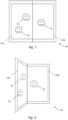
- the folding of a screen can result in a visible crease occurring where a part of the screen buckles slightly - this would typically occur in the area of the screen above the hinge. Such creases can remain visible even in the flat configuration described with reference to FIG. 1 above.
- compensation is performed for said potentially problematic sources of reflection identified in the operation 42.
- An example of an appropriate compensation would be re-lighting and/or re-colouring the areas of the display which are not affected by the reflection with a colour or brightness matching the perceived version of the reflected light source or object, such that the 'true' scene reflection appears to the user to 'blend' in to the new background.
- one or more imaging devices may be used to determine illumination sources and/or objects in the vicinity of a user device screen and potentially problematic reflection areas of the screen can be determined based on the locations of those illumination sources/objects relative to user angle and gaze position.
- FIG. 5 is a block diagram of a system, indicated generally by the reference numeral 50, in accordance with an example embodiment.
- the system 50 includes a user device screen 52 comprising a first display segment 52a and a second display segment 52b that can be folded relative to one another.
- a light source 56 is shown in the scene around in user device 52. Reflections from the light source 56 are visible to a user 54 due to reflections from the display 52 (as indicated by the dotted lines 57a and 57b).
- the light source 56 is positioned such that were there no crease area, reflections of the light source would not be visible to the user 54.
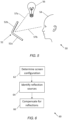
- FIG. 6 is a flow chart showing an algorithm, indicated generally by the reference numeral 60, in accordance with an example embodiment.
- the algorithm 60 starts at operation 62, where a configuration of a reconfigurable screen of a user device (such as the user device 52) is determined.
- Different configurations e.g. fold angles
- the operation 62 determines a fold angle between the first and second display segments of the user device screen 52. Changing the fold angle changes the nature of the geometric distortion of the screen in the area of a hinge between the displays in a way that may be predictable. Sensors are provided for determining the fold angle.
- potentially problematic sources of reflection are identified from a scene around the user device.
- one or more imaging devices such as cameras may be used to determine illumination sources and/or objects in the vicinity of a user device screen and potentially problematic reflection areas of the screen may be determined based on the locations of those illumination sources/objects and the relative angle of the user.
- Undesirable scene reflections occurring due to distorted areas of a flexible screen may be compensated by using knowledge of the current screen orientation to calculate the distorted shape of certain screen areas, and using that shape to calculate the appropriate light source directions to compensate for, along with the geometrical distortions on those sources.
- the directional calculation may also be enhanced using user gaze measurements, such that the relative position between the user's gaze point and the distorted screen area may be used in calculating the light sources requiring correction and in calculating a compensating pattern to display.
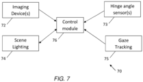
- FIG. 7 is a block diagram of a system, indicated generally by the reference numeral 70, in accordance with an example embodiment.
- the system 70 may be used to implement the algorithm 60 described above.
- the system 70 comprises imaging device(s) 72, hinge angle sensor(s) 73, a scene lighting module 74, a gaze tracking module 75 and a control module 76.
- the control module 76 may be used to implement the operation 66 of the algorithm 60 by compensating for reflections of a device having a reconfigurable screen.
- the imaging device(s) 72 (e.g. one or more cameras) provide images of a user and a scene to the control module 76.
- the one or more hinge angle sensors 73 are used to measure the angle between first and second display segments of the user device screen.
- some foldable mobile phones include angle sensing hardware to which applications can connect via a suitable application programming interface.
- the scene lighting module 74 is used to estimate the position(s) of light sources within a scene based, at least in part, on data from the imaging device(s) 72.
- the scene lighting module may determine the relative directions of light sources within the scene by directly analysing image data from the imaging device(s) 72 and calculating their angle to the device via known image analysis techniques.
- the scene lighting module may locate light sources in the scene by analysis of images of the user captured by the imaging device(s).
- the scene lighting module may include algorithms for performing corneal reflection imaging from images of the user's eyes, in which reflections of light sources from the scene are likely to be captured.
- the relative angle between the light sources and the device may then be calculated by knowledge of the spherical shape of the user's cornea and the angle to the user.
- This second example is likely to be advantageous where the field of view (FOV) of the imaging device(s) is insufficient to directly capture all light sources from a scene.
- FOV field of view
- the gaze tracking module 75 is used to estimate the user's gaze point on the screen.
- the gaze tracking module may, for example, estimate the user's gaze point by real time image analysis of images of the user captured by the imaging device(s) 72.
- known techniques e.g. neural network models
- landmarks such as eye corners and/or iris positions.
- the change in position of these landmarks may be input to a further software model to calculate the user's gaze position on the screen.
- These techniques may optionally be improved via a distance measurement to the user (e.g. via range-finding sensors on the device), and also optionally may be subject to generic and/or individual user calibration procedures.
- the gaze tracking module 75 may be used to determine a gaze direction of a viewer of the screen of the user device. For example, the relative position between the user's gaze point and a distorted screen area can be used in the determination (by the control module 76) of the light sources that require correction and the compensation required.
- the control module 76 may implement a specular correction algorithm for calculating appropriate correction patterns to apply to the screen.
- the control module 76 may compensate for potentially problematic sources of reflection based, at least in part, on the determined user gaze direction.
- Example compensations include selective dimming, relighting and/or recolouring areas of the screen within or outside the distorted area. For example, where a problematic reflection source is identified having a particular colour and calculated light intensity at the screen plane, the remainder of the screen may be recoloured and its brightness increased such that the reflected object appears to blend in to the newly altered background of the screen.
- shapes of detected reflection sources may be distorted from their "true" shape to match the distortion associated with a hinge position.
- FIG. 8 is a flow chart showing an algorithm, indicated generally by the reference numeral 80, in accordance with an example embodiment.
- the algorithm 80 starts at operation 81, where a user uses a user device (e.g. a foldable smartphone) containing one or more cameras.
- the camera(s) can be used to image lighting sources and objects in a scene so that the angles of the lighting sources/objects can be determined relative to the user device.
- the camera(s) can also be used to image the user to estimate the position and gaze angle of the user relative to the screen of the user device.
- a scene lighting algorithm (which may be implemented by the scene lighting module 74 described above) filters the possible light sources from the scene which match the range of acceptance angles associated with the particular distortion (the "specular reflections"), and communicates information such as the positions, shapes, colours, and other data relating to the specular reflections to a specular correction algorithm (which may be implemented by the control module 76 described above).
- the compensation pattern generated in the operation 86 is applied to the screen of the user device.
- FIG. 9 is a schematic diagram of components of one or more of the example embodiments described previously, which hereafter are referred to generically as a processing system 300.
- the processing system 300 may, for example, be the apparatus referred to in the claims below.
- the processing system 300 may have a processor 302, a memory 304 closely coupled to the processor and comprised of a RAM 314 and a ROM 312, and, optionally, a user input 310 and a display 318.
- the processing system 300 may comprise one or more network/apparatus interfaces 308 for connection to a network/apparatus, e.g. a modem which may be wired or wireless.
- the network/apparatus interface 308 may also operate as a connection to other apparatus such as device/apparatus which is not network side apparatus. Thus, direct connection between devices/apparatus without network participation is possible.
- the processor 302 is connected to each of the other components in order to control operation thereof.
- the memory 304 may comprise a non-volatile memory, such as a hard disk drive (HDD) or a solid state drive (SSD).
- the ROM 312 of the memory 304 stores, amongst other things, an operating system 315 and may store software applications 316.
- the RAM 314 of the memory 304 is used by the processor 302 for the temporary storage of data.
- the operating system 315 may contain code which, when executed by the processor implements aspects of the algorithms 40, 60 and 80 described above. Note that in the case of small device/apparatus the memory can be most suitable for small size usage i.e. not always a hard disk drive (HDD) or a solid state drive (SSD) is used.
- HDD hard disk drive
- SSD solid state drive
- the processing system 300 may also be associated with external software applications. These may be applications stored on a remote server device/apparatus and may run partly or exclusively on the remote server device/apparatus. These applications may be termed cloud-hosted applications.
- the processing system 300 may be in communication with the remote server device/apparatus in order to utilize the software application stored there.
- FIGS. 10A and 10B show tangible media, respectively a removable memory unit 365 and a compact disc (CD) 368, storing computer-readable code which when run by a computer may perform methods according to example embodiments described above.
- the removable memory unit 365 may be a memory stick, e.g. a USB memory stick, having internal memory 366 storing the computer-readable code.
- the internal memory 366 may be accessed by a computer system via a connector 367.
- the CD 368 may be a CD-ROM or a DVD or similar. Other forms of tangible storage media may be used.
- Tangible media can be any device/apparatus capable of storing data/information which data/information can be exchanged between devices/apparatus/network.
- references to computer program, instructions, code etc. should be understood to express software for a programmable processor firmware such as the programmable content of a hardware device/apparatus as instructions for a processor or configured or configuration settings for a fixed function device/apparatus, gate array, programmable logic device/apparatus, etc.
Landscapes
- Engineering & Computer Science (AREA)
- Theoretical Computer Science (AREA)
- General Engineering & Computer Science (AREA)
- Physics & Mathematics (AREA)
- General Physics & Mathematics (AREA)
- Human Computer Interaction (AREA)
- Computer Hardware Design (AREA)
- Mathematical Physics (AREA)
- Studio Devices (AREA)
- Image Processing (AREA)
Claims (10)
- Einrichtung, die Folgendes umfasst:einen klappbaren Bildschirm;einen oder mehrere Sensoren, die dazu ausgelegt sind, einen Klappwinkel des klappbaren Bildschirms zu bestimmen; undMittel zum Durchführen von Folgendem:Bestimmen einer Auslegung des klappbaren Bildschirms (10, 32, 52), wobei die Auslegung des klappbaren Bildschirms (10, 32, 52) den Klappwinkel umfasst;Bestimmen oder Abrufen von geometrischen Verzerrungsinformationen für den klappbaren Bildschirm (10, 32, 52) auf Basis der bestimmten Auslegung;Identifizieren von potenziell problematischen Quellen der Reflexion (38, 39, 56) anhand einer Szene um die Einrichtung mindestens teilweise auf Basis der bestimmten Auslegung und der geometrischen Verzerrungsinformationen; undKompensieren der potenziell problematischen Quellen der Reflexion (38, 39, 56).
- Einrichtung nach Anspruch 1, die ferner Mittel zum Durchführen von Folgendem umfasst:Bestimmen von Beleuchtungsquellen und/oder von Objekten, die gegen den Bildschirm (10, 32, 52) stoßen,wobei die Mittel zum Durchführen des Identifizierens der potenziell problematischen Quellen der Reflexion (38, 39, 56) die Quellen mindestens teilweise auf Basis eines Ortes der bestimmten Beleuchtungsquellen und/oder Objekte identifizieren.
- Einrichtung nach Anspruch 2, die ferner Mittel zum Durchführen von Folgendem umfasst:
Identifizieren von potenziell problematischen Reflexionsbereichen des Bildschirms (10, 32, 52) mindestens teilweise auf Basis von bestimmten Orten der Beleuchtungsquellen und/oder Objekte. - Einrichtung nach Anspruch 2 oder Anspruch 3, wobei die Mittel zum Durchführen des Bestimmens der Beleuchtungsquellen und/oder der Objekte eine oder mehrere Bildgebungsvorrichtungen umfassen.
- Einrichtung nach einem der Ansprüche 2 bis 4, wobei die Mittel zum Durchführen des Bestimmens der Beleuchtungsquellen und/oder der Objekte eine Hornhautreflexionsbildgebung umfassen.
- Einrichtung nach einem der Ansprüche 2 bis 5, die ferner Mittel zum Durchführen von Folgendem umfasst:
Bestimmen eines Winkels und/oder einer Beleuchtungsfarbe der bestimmten Beleuchtungsquellen und/oder Objekte relativ zum Bildschirm (10, 32, 52) zur Verwendung beim Identifizieren der potenziell problematischen Quellen der Reflexion (38, 39, 56) und/oder zur Verwendung beim Kompensieren der potenziell problematischen Quellen der Reflexion (38, 39, 56). - Einrichtung nach einem der vorhergehenden Ansprüche, die ferner Mittel zum Durchführen von Folgendem umfasst:
Bestimmen einer Blickrichtung eines Betrachters des Bildschirms (10, 32, 52) der Benutzervorrichtung. - Einrichtung nach Anspruch 7, wobei die Mittel zum Durchführen des Identifizierens der potenziell problematischen Quellen der Reflexion (38, 39, 56) die Quellen mindestens teilweise auf Basis der bestimmten Benutzerblickrichtung identifizieren.
- Einrichtung nach Anspruch 7 oder Anspruch 8, die ferner Mittel zum Durchführen von Folgendem umfasst:
Bestimmen einer Kompensation für die potenziell problematischen Quellen der Reflexion (38, 39, 56) mindestens teilweise auf Basis der bestimmten Benutzerblickrichtung. - Einrichtung nach einem der vorhergehenden Ansprüche, wobei die Mittel zum Durchführen einer Kompensation für die potenziell problematischen Quellen der Reflexion (38, 39, 56) eine Spiegelreflexkorrektur umfassen.
Priority Applications (2)
| Application Number | Priority Date | Filing Date | Title |
|---|---|---|---|
| EP21159818.0A EP4053682B1 (de) | 2021-03-01 | 2021-03-01 | Benutzervorrichtungsbildschirm |
| US17/680,769 US11636792B2 (en) | 2021-03-01 | 2022-02-25 | Reconfigurable user device screen compensating problematic sources of reflection |
Applications Claiming Priority (1)
| Application Number | Priority Date | Filing Date | Title |
|---|---|---|---|
| EP21159818.0A EP4053682B1 (de) | 2021-03-01 | 2021-03-01 | Benutzervorrichtungsbildschirm |
Publications (2)
| Publication Number | Publication Date |
|---|---|
| EP4053682A1 EP4053682A1 (de) | 2022-09-07 |
| EP4053682B1 true EP4053682B1 (de) | 2025-07-02 |
Family
ID=74844753
Family Applications (1)
| Application Number | Title | Priority Date | Filing Date |
|---|---|---|---|
| EP21159818.0A Active EP4053682B1 (de) | 2021-03-01 | 2021-03-01 | Benutzervorrichtungsbildschirm |
Country Status (2)
| Country | Link |
|---|---|
| US (1) | US11636792B2 (de) |
| EP (1) | EP4053682B1 (de) |
Family Cites Families (12)
| Publication number | Priority date | Publication date | Assignee | Title |
|---|---|---|---|---|
| US7764846B2 (en) * | 2006-12-12 | 2010-07-27 | Xerox Corporation | Adaptive red eye correction |
| US20120229487A1 (en) | 2011-03-11 | 2012-09-13 | Nokia Corporation | Method and Apparatus for Reflection Compensation |
| US9812074B2 (en) | 2011-03-18 | 2017-11-07 | Blackberry Limited | System and method for foldable display |
| KR20150039458A (ko) * | 2013-10-02 | 2015-04-10 | 삼성전자주식회사 | 디스플레이장치 및 그 제어방법 |
| CN107111863B (zh) | 2014-12-10 | 2020-11-17 | 瑞典爱立信有限公司 | 角膜成像的设备和方法 |
| KR20170054056A (ko) * | 2015-11-09 | 2017-05-17 | 삼성전자주식회사 | 사용자 인터페이스를 제공하는 방법 및 모바일 디바이스 |
| KR102471916B1 (ko) * | 2016-06-03 | 2022-11-29 | 엘지전자 주식회사 | 모바일 디바이스 및 그 제어 방법 |
| US9858848B1 (en) * | 2016-06-09 | 2018-01-02 | International Business Machines Corporation | Dynamic display adjustment on a transparent flexible display |
| KR102618319B1 (ko) | 2016-09-20 | 2023-12-27 | 삼성디스플레이 주식회사 | 플렉서블 표시 장치 및 그 구동방법 |
| CA3047805A1 (en) * | 2016-12-20 | 2018-06-28 | Irystec Software Inc. | System and method for compensation of reflection on a display device |
| KR102779686B1 (ko) | 2019-04-05 | 2025-03-12 | 삼성전자 주식회사 | 디스플레이의 굴곡부의 시인성을 향상시키는 전자 장치 및 전자 장치의 동작 방법 |
| US10948729B2 (en) | 2019-04-16 | 2021-03-16 | Facebook Technologies, Llc | Keep-out zone for in-field light sources of a head mounted display |
-
2021
- 2021-03-01 EP EP21159818.0A patent/EP4053682B1/de active Active
-
2022
- 2022-02-25 US US17/680,769 patent/US11636792B2/en active Active
Also Published As
| Publication number | Publication date |
|---|---|
| US11636792B2 (en) | 2023-04-25 |
| EP4053682A1 (de) | 2022-09-07 |
| US20220277678A1 (en) | 2022-09-01 |
Similar Documents
| Publication | Publication Date | Title |
|---|---|---|
| EP2928180B1 (de) | Bildverarbeitungsgerät, verfahren zur steuerung eines bildverarbeitungsgerätes und programm | |
| TWI547828B (zh) | 感測器與投射器之校準技術 | |
| EP3637763B1 (de) | Farbdetektionsverfahren und -endgerät | |
| US9785233B2 (en) | Systems and methods of eye tracking calibration | |
| CN107545592B (zh) | 动态摄像机校准 | |
| JP5900468B2 (ja) | Ar表示装置、処理内容設定装置、処理内容設定方法およびプログラム | |
| JP7708264B2 (ja) | 情報処理装置、情報処理方法およびコンピュータプログラム | |
| JP2017539108A (ja) | 眼球輻輳に基づいたディスプレイ視認性 | |
| US20220028094A1 (en) | Systems and methods for facilitating the identifying of correspondences between images experiencing motion blur | |
| WO2022019975A1 (en) | Systems and methods for reducing a search area for identifying correspondences between images | |
| TW201626786A (zh) | 周圍光基礎的影像調整 | |
| KR20190088644A (ko) | 광학식 이미지 안정화 움직임에 의한 이미지의 변화를 보상하기 위한 장치 및 방법 | |
| US20160119602A1 (en) | Control apparatus, control method, and storage medium | |
| US20190156488A1 (en) | Image processing apparatus and method of controlling the same and recording medium | |
| KR102251307B1 (ko) | 거리측정 기능을 갖는 열상 카메라 시스템 | |
| JP6425406B2 (ja) | 情報処理装置、情報処理方法、プログラム | |
| JP7392262B2 (ja) | 検出装置、情報処理装置、検出方法、検出プログラム、及び検出システム | |
| US20190243456A1 (en) | Method and device for recognizing a gesture, and display device | |
| US9979858B2 (en) | Image processing apparatus, image processing method and program | |
| EP4053682B1 (de) | Benutzervorrichtungsbildschirm | |
| JP5805013B2 (ja) | 撮像画像表示装置、撮像画像表示方法、プログラム | |
| US10691203B2 (en) | Image sound output device, image sound output method and image sound output program | |
| US10310668B2 (en) | Touch screen display system and a method for controlling a touch screen display system | |
| JP2019101753A (ja) | 物体形状測定装置及びその制御方法、並びにプログラム | |
| JPWO2019159759A1 (ja) | 操作検出装置及び操作検出方法 |
Legal Events
| Date | Code | Title | Description |
|---|---|---|---|
| PUAI | Public reference made under article 153(3) epc to a published international application that has entered the european phase |
Free format text: ORIGINAL CODE: 0009012 |
|
| STAA | Information on the status of an ep patent application or granted ep patent |
Free format text: STATUS: THE APPLICATION HAS BEEN PUBLISHED |
|
| AK | Designated contracting states |
Kind code of ref document: A1 Designated state(s): AL AT BE BG CH CY CZ DE DK EE ES FI FR GB GR HR HU IE IS IT LI LT LU LV MC MK MT NL NO PL PT RO RS SE SI SK SM TR |
|
| STAA | Information on the status of an ep patent application or granted ep patent |
Free format text: STATUS: REQUEST FOR EXAMINATION WAS MADE |
|
| 17P | Request for examination filed |
Effective date: 20230303 |
|
| RBV | Designated contracting states (corrected) |
Designated state(s): AL AT BE BG CH CY CZ DE DK EE ES FI FR GB GR HR HU IE IS IT LI LT LU LV MC MK MT NL NO PL PT RO RS SE SI SK SM TR |
|
| STAA | Information on the status of an ep patent application or granted ep patent |
Free format text: STATUS: EXAMINATION IS IN PROGRESS |
|
| 17Q | First examination report despatched |
Effective date: 20240212 |
|
| GRAP | Despatch of communication of intention to grant a patent |
Free format text: ORIGINAL CODE: EPIDOSNIGR1 |
|
| STAA | Information on the status of an ep patent application or granted ep patent |
Free format text: STATUS: GRANT OF PATENT IS INTENDED |
|
| INTG | Intention to grant announced |
Effective date: 20250127 |
|
| GRAS | Grant fee paid |
Free format text: ORIGINAL CODE: EPIDOSNIGR3 |
|
| GRAA | (expected) grant |
Free format text: ORIGINAL CODE: 0009210 |
|
| STAA | Information on the status of an ep patent application or granted ep patent |
Free format text: STATUS: THE PATENT HAS BEEN GRANTED |
|
| AK | Designated contracting states |
Kind code of ref document: B1 Designated state(s): AL AT BE BG CH CY CZ DE DK EE ES FI FR GB GR HR HU IE IS IT LI LT LU LV MC MK MT NL NO PL PT RO RS SE SI SK SM TR |
|
| REG | Reference to a national code |
Ref country code: GB Ref legal event code: FG4D |
|
| REG | Reference to a national code |
Ref country code: CH Ref legal event code: EP |
|
| REG | Reference to a national code |
Ref country code: DE Ref legal event code: R096 Ref document number: 602021033160 Country of ref document: DE |
|
| REG | Reference to a national code |
Ref country code: IE Ref legal event code: FG4D |
|
| REG | Reference to a national code |
Ref country code: NL Ref legal event code: MP Effective date: 20250702 |
|
| PG25 | Lapsed in a contracting state [announced via postgrant information from national office to epo] |
Ref country code: PT Free format text: LAPSE BECAUSE OF FAILURE TO SUBMIT A TRANSLATION OF THE DESCRIPTION OR TO PAY THE FEE WITHIN THE PRESCRIBED TIME-LIMIT Effective date: 20251103 |
|
| PG25 | Lapsed in a contracting state [announced via postgrant information from national office to epo] |
Ref country code: NL Free format text: LAPSE BECAUSE OF FAILURE TO SUBMIT A TRANSLATION OF THE DESCRIPTION OR TO PAY THE FEE WITHIN THE PRESCRIBED TIME-LIMIT Effective date: 20250702 |
|
| REG | Reference to a national code |
Ref country code: AT Ref legal event code: MK05 Ref document number: 1809980 Country of ref document: AT Kind code of ref document: T Effective date: 20250702 |
|
| PG25 | Lapsed in a contracting state [announced via postgrant information from national office to epo] |
Ref country code: IS Free format text: LAPSE BECAUSE OF FAILURE TO SUBMIT A TRANSLATION OF THE DESCRIPTION OR TO PAY THE FEE WITHIN THE PRESCRIBED TIME-LIMIT Effective date: 20251102 |
|
| PG25 | Lapsed in a contracting state [announced via postgrant information from national office to epo] |
Ref country code: NO Free format text: LAPSE BECAUSE OF FAILURE TO SUBMIT A TRANSLATION OF THE DESCRIPTION OR TO PAY THE FEE WITHIN THE PRESCRIBED TIME-LIMIT Effective date: 20251002 |
|
| REG | Reference to a national code |
Ref country code: LT Ref legal event code: MG9D |
|
| PG25 | Lapsed in a contracting state [announced via postgrant information from national office to epo] |
Ref country code: AT Free format text: LAPSE BECAUSE OF FAILURE TO SUBMIT A TRANSLATION OF THE DESCRIPTION OR TO PAY THE FEE WITHIN THE PRESCRIBED TIME-LIMIT Effective date: 20250702 |
|
| PG25 | Lapsed in a contracting state [announced via postgrant information from national office to epo] |
Ref country code: FI Free format text: LAPSE BECAUSE OF FAILURE TO SUBMIT A TRANSLATION OF THE DESCRIPTION OR TO PAY THE FEE WITHIN THE PRESCRIBED TIME-LIMIT Effective date: 20250702 |
|
| PG25 | Lapsed in a contracting state [announced via postgrant information from national office to epo] |
Ref country code: HR Free format text: LAPSE BECAUSE OF FAILURE TO SUBMIT A TRANSLATION OF THE DESCRIPTION OR TO PAY THE FEE WITHIN THE PRESCRIBED TIME-LIMIT Effective date: 20250702 |
|
| PG25 | Lapsed in a contracting state [announced via postgrant information from national office to epo] |
Ref country code: GR Free format text: LAPSE BECAUSE OF FAILURE TO SUBMIT A TRANSLATION OF THE DESCRIPTION OR TO PAY THE FEE WITHIN THE PRESCRIBED TIME-LIMIT Effective date: 20251003 |
|
| PG25 | Lapsed in a contracting state [announced via postgrant information from national office to epo] |
Ref country code: SE Free format text: LAPSE BECAUSE OF FAILURE TO SUBMIT A TRANSLATION OF THE DESCRIPTION OR TO PAY THE FEE WITHIN THE PRESCRIBED TIME-LIMIT Effective date: 20250702 Ref country code: CZ Free format text: LAPSE BECAUSE OF FAILURE TO SUBMIT A TRANSLATION OF THE DESCRIPTION OR TO PAY THE FEE WITHIN THE PRESCRIBED TIME-LIMIT Effective date: 20250702 |
|
| PG25 | Lapsed in a contracting state [announced via postgrant information from national office to epo] |
Ref country code: LV Free format text: LAPSE BECAUSE OF FAILURE TO SUBMIT A TRANSLATION OF THE DESCRIPTION OR TO PAY THE FEE WITHIN THE PRESCRIBED TIME-LIMIT Effective date: 20250702 |
|
| PG25 | Lapsed in a contracting state [announced via postgrant information from national office to epo] |
Ref country code: PL Free format text: LAPSE BECAUSE OF FAILURE TO SUBMIT A TRANSLATION OF THE DESCRIPTION OR TO PAY THE FEE WITHIN THE PRESCRIBED TIME-LIMIT Effective date: 20250702 Ref country code: BG Free format text: LAPSE BECAUSE OF FAILURE TO SUBMIT A TRANSLATION OF THE DESCRIPTION OR TO PAY THE FEE WITHIN THE PRESCRIBED TIME-LIMIT Effective date: 20250702 |
|
| PG25 | Lapsed in a contracting state [announced via postgrant information from national office to epo] |
Ref country code: RS Free format text: LAPSE BECAUSE OF FAILURE TO SUBMIT A TRANSLATION OF THE DESCRIPTION OR TO PAY THE FEE WITHIN THE PRESCRIBED TIME-LIMIT Effective date: 20251002 |
|
| PG25 | Lapsed in a contracting state [announced via postgrant information from national office to epo] |
Ref country code: ES Free format text: LAPSE BECAUSE OF FAILURE TO SUBMIT A TRANSLATION OF THE DESCRIPTION OR TO PAY THE FEE WITHIN THE PRESCRIBED TIME-LIMIT Effective date: 20250702 |
|
| PG25 | Lapsed in a contracting state [announced via postgrant information from national office to epo] |
Ref country code: SM Free format text: LAPSE BECAUSE OF FAILURE TO SUBMIT A TRANSLATION OF THE DESCRIPTION OR TO PAY THE FEE WITHIN THE PRESCRIBED TIME-LIMIT Effective date: 20250702 |
|
| PGFP | Annual fee paid to national office [announced via postgrant information from national office to epo] |
Ref country code: GB Payment date: 20260202 Year of fee payment: 6 |
|
| PG25 | Lapsed in a contracting state [announced via postgrant information from national office to epo] |
Ref country code: DK Free format text: LAPSE BECAUSE OF FAILURE TO SUBMIT A TRANSLATION OF THE DESCRIPTION OR TO PAY THE FEE WITHIN THE PRESCRIBED TIME-LIMIT Effective date: 20250702 |
|
| PGFP | Annual fee paid to national office [announced via postgrant information from national office to epo] |
Ref country code: DE Payment date: 20260204 Year of fee payment: 6 |
|
| PG25 | Lapsed in a contracting state [announced via postgrant information from national office to epo] |
Ref country code: IT Free format text: LAPSE BECAUSE OF FAILURE TO SUBMIT A TRANSLATION OF THE DESCRIPTION OR TO PAY THE FEE WITHIN THE PRESCRIBED TIME-LIMIT Effective date: 20250702 |