EP4054032A1 - Support de trapèze pour un panier en fil de fer - Google Patents
Support de trapèze pour un panier en fil de fer Download PDFInfo
- Publication number
- EP4054032A1 EP4054032A1 EP22159076.3A EP22159076A EP4054032A1 EP 4054032 A1 EP4054032 A1 EP 4054032A1 EP 22159076 A EP22159076 A EP 22159076A EP 4054032 A1 EP4054032 A1 EP 4054032A1
- Authority
- EP
- European Patent Office
- Prior art keywords
- wire basket
- support bracket
- main member
- wire
- longitudinal wires
- Prior art date
- Legal status (The legal status is an assumption and is not a legal conclusion. Google has not performed a legal analysis and makes no representation as to the accuracy of the status listed.)
- Granted
Links
Images





Classifications
-
- H—ELECTRICITY
- H02—GENERATION; CONVERSION OR DISTRIBUTION OF ELECTRIC POWER
- H02G—INSTALLATION OF ELECTRIC CABLES OR LINES, OR OF COMBINED OPTICAL AND ELECTRIC CABLES OR LINES
- H02G3/00—Installations of electric cables or lines or protective tubing therefor in or on buildings, equivalent structures or vehicles
- H02G3/02—Details
- H02G3/04—Protective tubing or conduits, e.g. cable ladders or cable troughs
- H02G3/0437—Channels
- H02G3/0443—Channels formed by wire or analogous netting
-
- H—ELECTRICITY
- H02—GENERATION; CONVERSION OR DISTRIBUTION OF ELECTRIC POWER
- H02G—INSTALLATION OF ELECTRIC CABLES OR LINES, OR OF COMBINED OPTICAL AND ELECTRIC CABLES OR LINES
- H02G3/00—Installations of electric cables or lines or protective tubing therefor in or on buildings, equivalent structures or vehicles
- H02G3/02—Details
- H02G3/04—Protective tubing or conduits, e.g. cable ladders or cable troughs
- H02G3/0456—Ladders or other supports
-
- F—MECHANICAL ENGINEERING; LIGHTING; HEATING; WEAPONS; BLASTING
- F16—ENGINEERING ELEMENTS AND UNITS; GENERAL MEASURES FOR PRODUCING AND MAINTAINING EFFECTIVE FUNCTIONING OF MACHINES OR INSTALLATIONS; THERMAL INSULATION IN GENERAL
- F16L—PIPES; JOINTS OR FITTINGS FOR PIPES; SUPPORTS FOR PIPES, CABLES OR PROTECTIVE TUBING; MEANS FOR THERMAL INSULATION IN GENERAL
- F16L3/00—Supports for pipes, cables or protective tubing, e.g. hangers, holders, clamps, cleats, clips, brackets
- F16L3/26—Supports for pipes, cables or protective tubing, e.g. hangers, holders, clamps, cleats, clips, brackets specially adapted for supporting the pipes all along their length, e.g. pipe channels or ducts
-
- H—ELECTRICITY
- H02—GENERATION; CONVERSION OR DISTRIBUTION OF ELECTRIC POWER
- H02G—INSTALLATION OF ELECTRIC CABLES OR LINES, OR OF COMBINED OPTICAL AND ELECTRIC CABLES OR LINES
- H02G3/00—Installations of electric cables or lines or protective tubing therefor in or on buildings, equivalent structures or vehicles
- H02G3/26—Installations of cables, lines, or separate protective tubing therefor directly on or in walls, ceilings, or floors
- H02G3/263—Installation, e.g. suspension, of conduit channels or other supports
Definitions
- the present invention relates to a bracket for a wire basket, and more particularly to a trapeze support bracket for wire baskets in a wire basket system.
- Wire basket systems generally provide support for cables such as electrical wiring, conduit and data transmission lines. Each wire basket is formed from interconnected metal wires. The wire baskets are connected to other wire baskets at intersections to route the cables and form a wire basket system. The intersections may be three-way intersections, or T-intersection, or four-way intersections. The wire basket system may be supported on cabinets in data center. The wire basket system may also be supported by wall mount brackets or trapeze brackets secured to a ceiling.
- a support bracket designed to receive a threaded rod for securing a wire basket to a ceiling in a wire basket system.
- the support bracket has a main member with a top, a bottom, a first end, a second end, a first side, and a second side.
- a first arm extends downwardly from the first side of the main member.
- a second arm extends downwardly from the second side of the main member.
- the first arm and the second arm each including a J-shaped hook. The J-shaped hooks of the first and second arms are aligned to enable the support bracket to receive a wire of the wire basket in the wire basket system.
- FIG. 1 illustrates a perspective view of the trapeze support bracket 50 of the present invention.
- the trapeze support bracket 50 has a main member 52 with a top 54, a bottom 56, a first end 58, a second end 60, a first side 62 and a second side 64.
- the center of the main member 52 includes an opening 66 that extends from the top 54 of the main member 52 to the bottom 56 of the main member 52.
- the opening 66 receives a threaded rod 90 (shown in FIG. 2 ) to enable the trapeze support bracket 50 to be secured to a ceiling.
- An alternate installation to the rod secured to the ceiling is that the rod may be supported from below.
- the rod may be anchored to a cabinet in the data center (not illustrated).
- the opening 66 in the main member 52 is designed to receive 1 ⁇ 4", 3/8", or 1 ⁇ 2" threaded rods.
- the trapeze support bracket 50 includes a first arm 68 that extends downward from the first side 62 of the main member 52 and a second arm 72 that extends downward from the second side 64 of the main member 52.
- the first arm 68 and the second arm 72 extend beyond the first end 58 of the main member.
- the first arm 68 and the second arm 72 each include a J-shaped hook 70, 74, respectively.
- the J-shaped hooks 70, 74 of the first arm 68 and the second arm 72, respectively, are aligned with each other to enable the trapeze support bracket 50 to receive a longitudinal wire 104, 106, or 108 of the wire basket 100.
- the first end 58 of the main member 52 includes an outer edge 76 and an indented edge 78.
- the indented edge 78 is centered between the first side 62 and the second side 64 of the trapeze support bracket 50.
- a latch 80 extends from the indented edge 78 at an angle towards the extended first and second arms 68, 72, respectively.
- the latch 80 includes a curved upper member 82 that leads to a generally rectangular bottom member 84.
- the latch 80 extends between the first and second arms 68, 72, respectively, such that the latch 80 engages the longitudinal wire 104, 106, or 108 of the wire basket 100 when the longitudinal wire 104, 106, or 108 is positioned in the aligned J-hooks 70, 74 of the first and second arms 68, 72, respectively.
- FIGS. 2-7 illustrate a wire basket 100 and the trapeze support bracket 50 installed on the wire basket 100.
- the wire basket 100 is formed from a plurality of parallel and perpendicular metal wires that form a mesh pattern.
- the wire basket 100 includes a plurality of transverse or cross wires 102 that extend from one side, across the bottom of the wire basket, to the opposite side.
- the wire basket 100 also includes a plurality of parallel longitudinal wires 104, 106, 108 that extend the length of the wire basket 100. Bottom longitudinal wires 108 are positioned along the bottom of the transverse wires 102 to form the bottom 110 of the wire basket 100.
- An upper longitudinal wire 104 and a lower longitudinal wire 106 are positioned along the tops and each side of the transverse wires 102 to form the side walls 112 of the wire basket 100.
- the mesh pattern forms a wire basket 100 that supports cables and routes cables along the length of the wire basket 100.
- the wire baskets are often supported by trapeze brackets that extend under the wire basket, wall mount brackets or brackets secured to threaded rods affixed to ceilings.
- the trapeze support bracket of the present invention engages threaded rods in various positions along the wire basket to support the wire basket.
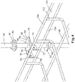
- FIGS. 4-7 illustrate the installation of the trapeze support bracket 50.
- a threaded rod 90 with a washer 92 and nut 94 is installed in the center opening 66 of the main member 52 of the trapeze bracket 50.
- a second washer 92 and nut 94 are installed on the threaded rod 90 and positioned to engage the bottom 56 of the main member 52 of the trapeze support bracket 50 once fully installed.
- FIGS. 4-7 illustrate the installation of the trapeze support bracket 50.
- the trapeze support bracket 50 is positioned below the upper longitudinal wire 104 with the upper longitudinal wire 104 positioned against the outer edge 76 of the main member 52 above the J-hooks 70, 74 in the first and second arms 68, 72, respectively. As illustrated in FIGS. 5 and 6B , the trapeze support bracket 50 is raised so it is snapped onto the upper longitudinal wire 104. The upper longitudinal wire 104 is positioned within the J-hooks 70, 74 in the first and second arms 68, 72 and the latch 80 engages the upper longitudinal wire 104.
- the bottom nut 94 and washer 92 are raised to engage the bottom 56 of the main member 52 of the trapeze support bracket 50 and the top nut 94 and washer 92 are lowered to engage the top 54 of the main member 52 of the trapeze support bracket 50 to secure the trapeze support bracket 50 to the threaded rod 90.
- FIG. 8 illustrates the trapeze support bracket 50 installed on the lower longitudinal wire 106 of the side wall 112 of the wire basket 100.
- the trapeze support bracket 50 is designed to capture one of the longitudinal wires 104, 106, or 108 of the wire basket 100.
- the trapeze support bracket 50 is snapped onto the lower longitudinal wire 106 of the wire basket side wall 112 in the same fashion as described above with respect to the upper longitudinal wire 104.
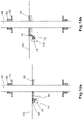
- FIGS. 9 , 10A, and 10B illustrate the trapeze support bracket 50 installed on one of the bottom longitudinal wires 108.
- the trapeze support bracket 50 is snapped onto the bottom longitudinal wire 108 in the same fashion as described above with respect to the upper longitudinal wire 104 and the lower longitudinal wire 106.
- the ability for the trapeze support bracket 50 to snap on to the bottom longitudinal wires 108 provides extra support for the wire basket 100. This is important when the wire basket sections intersect, and sidewalls of the wire basket are cut to accommodate the intersections. When sidewalls of the wire basket are removed, the wire baskets require extra support to safely maintain the cables routed therein.
- the trapeze support bracket 50 of the present invention is installed on a bottom longitudinal wire 108 in the middle of the wire basket intersection, the trapeze support bracket 50 greatly improves the strength of the wire basket 100 and reduces deflection of the wire basket 100. This provides support for a greater cable load routed in the wire basket system.
- FIG. 10A illustrate a cross sectional view of the trapeze support bracket 50 before it is installed on the bottom longitudinal wire 108.
- FIG. 10B illustrates a cross sectional view of the trapezes support bracket 50 partially installed on one of the bottom longitudinal wires 108.
- the bottom longitudinal wire 108 snaps into the J-hooks 70, 74 of the first and second arms 68, 70, respectively, and the latch 80 engages the bottom longitudinal wire 108.
- the trapeze support bracket 50 does not protrude into the wire basket 100 which allows for safely routing the cables within the wire basket 100.
Landscapes
- Engineering & Computer Science (AREA)
- Architecture (AREA)
- Civil Engineering (AREA)
- Structural Engineering (AREA)
- General Engineering & Computer Science (AREA)
- Mechanical Engineering (AREA)
- Details Of Indoor Wiring (AREA)
- Rigid Containers With Two Or More Constituent Elements (AREA)
- Supports Or Holders For Household Use (AREA)
- Load-Engaging Elements For Cranes (AREA)
- Mutual Connection Of Rods And Tubes (AREA)
- Suspension Of Electric Lines Or Cables (AREA)
Applications Claiming Priority (2)
| Application Number | Priority Date | Filing Date | Title |
|---|---|---|---|
| US202163155023P | 2021-03-01 | 2021-03-01 | |
| US17/592,564 US11870228B2 (en) | 2021-03-01 | 2022-02-04 | Trapeze support bracket for a wire basket |
Publications (2)
| Publication Number | Publication Date |
|---|---|
| EP4054032A1 true EP4054032A1 (fr) | 2022-09-07 |
| EP4054032B1 EP4054032B1 (fr) | 2025-06-18 |
Family
ID=80624008
Family Applications (1)
| Application Number | Title | Priority Date | Filing Date |
|---|---|---|---|
| EP22159076.3A Active EP4054032B1 (fr) | 2021-03-01 | 2022-02-28 | Support de trapèze pour un panier en fil de fer |
Country Status (5)
| Country | Link |
|---|---|
| US (1) | US11870228B2 (fr) |
| EP (1) | EP4054032B1 (fr) |
| JP (1) | JP7665550B2 (fr) |
| CN (1) | CN216819285U (fr) |
| MX (1) | MX2022002040A (fr) |
Families Citing this family (1)
| Publication number | Priority date | Publication date | Assignee | Title |
|---|---|---|---|---|
| JP7710019B2 (ja) * | 2023-11-14 | 2025-07-17 | 楽天グループ株式会社 | 情報管理装置、情報管理システム、情報管理方法及びプログラム |
Citations (6)
| Publication number | Priority date | Publication date | Assignee | Title |
|---|---|---|---|---|
| US20010044992A1 (en) * | 2000-05-26 | 2001-11-29 | Paul Hettich Gmbh & Co. | Quick fixing element |
| EP1197698A1 (fr) * | 2000-10-11 | 2002-04-17 | Krieg & Zivy Industries | Attache de suspension |
| EP1376808A1 (fr) * | 2002-06-28 | 2004-01-02 | Planet Wattohm | Dispositif de fixation à support d'un conduit de cheminement de câbles et système comprenant un conduit et un tel dispositif |
| EP2028739A1 (fr) * | 2007-08-22 | 2009-02-25 | Wesley Thompson Lynn | Montage de paniers de câbles et similaires |
| FR2929459A1 (fr) * | 2008-03-31 | 2009-10-02 | I C M Group Sa | Dispositif de fixation d'un chemin de cables en fils sur une tige filetee |
| EP3012929A1 (fr) * | 2014-10-25 | 2016-04-27 | Zurecon AG | Dispositif de guidage de câble doté d'un fonctionnement continu en cas d'incendie |
Family Cites Families (15)
| Publication number | Priority date | Publication date | Assignee | Title |
|---|---|---|---|---|
| US3806994A (en) | 1972-08-04 | 1974-04-30 | P Lankford | Fastening device for reinforcing rods |
| US4607818A (en) * | 1983-08-30 | 1986-08-26 | Levolor Lorentzen, Inc. | Installation bracket for venetian blind head rail |
| US5180130A (en) * | 1990-11-26 | 1993-01-19 | Kenney Manufacturing Company | Supporting bracket and headrail combination for a window blind |
| US5230493A (en) * | 1992-01-21 | 1993-07-27 | Luoto Donald W | Hidden mounting bracket for a venetian blind or window covering headrail |
| US6254040B1 (en) | 1998-10-26 | 2001-07-03 | William James Mc Grath | Mounting angle clamp for attaching additional structures to hanging rod |
| DE60000356T2 (de) * | 1999-02-05 | 2003-01-23 | Turnils Ab, Alingsaas | Haltebügel |
| EP1074773A1 (fr) | 1999-08-03 | 2001-02-07 | Thomas & Betts International, Inc. | Collier de support de câble et dispositif de fixation associé |
| US6471171B1 (en) | 2001-12-28 | 2002-10-29 | Panduit Corp. | 2-piece ladder rack bracket |
| US7073761B2 (en) | 2004-01-16 | 2006-07-11 | Bellsouth Intellectual Property Corporation | Communication cable support |
| US8602365B2 (en) | 2006-04-14 | 2013-12-10 | Cooper Technologies Company | Hanger for hanging an object from a support rod |
| US7661915B2 (en) | 2006-10-02 | 2010-02-16 | Whipple Charles E | Trapeze hanger |
| US8540090B2 (en) | 2009-05-19 | 2013-09-24 | Panduit Corp. | Telescoping wire cable tray system |
| US8424814B2 (en) | 2010-05-19 | 2013-04-23 | Panduit Corp. | Cable tray cable routing system |
| FR3009656B1 (fr) * | 2013-08-12 | 2017-03-03 | Gewiss France Sas | Element de fixation pour goulotte de chemin de cables et chemin de cables comprenant un tel element de fixation |
| US20150078809A1 (en) * | 2013-09-15 | 2015-03-19 | Richard Gregg Winn | Cable tray splice and support |
-
2022
- 2022-02-04 US US17/592,564 patent/US11870228B2/en active Active
- 2022-02-17 MX MX2022002040A patent/MX2022002040A/es unknown
- 2022-02-28 EP EP22159076.3A patent/EP4054032B1/fr active Active
- 2022-02-28 CN CN202220417964.6U patent/CN216819285U/zh active Active
- 2022-02-28 JP JP2022029444A patent/JP7665550B2/ja active Active
Patent Citations (6)
| Publication number | Priority date | Publication date | Assignee | Title |
|---|---|---|---|---|
| US20010044992A1 (en) * | 2000-05-26 | 2001-11-29 | Paul Hettich Gmbh & Co. | Quick fixing element |
| EP1197698A1 (fr) * | 2000-10-11 | 2002-04-17 | Krieg & Zivy Industries | Attache de suspension |
| EP1376808A1 (fr) * | 2002-06-28 | 2004-01-02 | Planet Wattohm | Dispositif de fixation à support d'un conduit de cheminement de câbles et système comprenant un conduit et un tel dispositif |
| EP2028739A1 (fr) * | 2007-08-22 | 2009-02-25 | Wesley Thompson Lynn | Montage de paniers de câbles et similaires |
| FR2929459A1 (fr) * | 2008-03-31 | 2009-10-02 | I C M Group Sa | Dispositif de fixation d'un chemin de cables en fils sur une tige filetee |
| EP3012929A1 (fr) * | 2014-10-25 | 2016-04-27 | Zurecon AG | Dispositif de guidage de câble doté d'un fonctionnement continu en cas d'incendie |
Also Published As
| Publication number | Publication date |
|---|---|
| US11870228B2 (en) | 2024-01-09 |
| MX2022002040A (es) | 2022-09-02 |
| JP7665550B2 (ja) | 2025-04-21 |
| EP4054032B1 (fr) | 2025-06-18 |
| CN216819285U (zh) | 2022-06-24 |
| US20220278512A1 (en) | 2022-09-01 |
| JP2022133255A (ja) | 2022-09-13 |
Similar Documents
| Publication | Publication Date | Title |
|---|---|---|
| US8540090B2 (en) | Telescoping wire cable tray system | |
| US6409031B1 (en) | Ceiling mounted rack | |
| US6672022B2 (en) | Cable tray support system | |
| AU748160B2 (en) | Flexible cable management system | |
| CA2663381C (fr) | Systeme de support de cable suspendu | |
| US6361000B1 (en) | Flexible cable management system | |
| US20030178535A1 (en) | Cable tray apparatus and method | |
| KR101294101B1 (ko) | 와이어형 케이블 레이스웨이, 특히 가정용 케이블레이스웨이 | |
| US6959898B1 (en) | Cable support and distribution system and method | |
| US20020023888A1 (en) | Ceiling mounted rack | |
| US11870228B2 (en) | Trapeze support bracket for a wire basket | |
| US11784475B2 (en) | Intersection system for overhead cable trays | |
| US20040245411A1 (en) | Modular cable support system | |
| US20010007341A1 (en) | Flexible cable management system | |
| US6592082B1 (en) | Wire chase rung | |
| EP1070894A3 (fr) | Support de câble et système et méthode de distribution | |
| CN111525477A (zh) | 一种天花板上的设备的布线系统 | |
| CN218040548U (zh) | 用于线缆托架的交叉系统及包括其的线缆托架系统 | |
| EP2028739A1 (fr) | Montage de paniers de câbles et similaires | |
| KR102835744B1 (ko) | 케이블 거치대 | |
| JP6756183B2 (ja) | 吊り下げ用照明器具、連結具及び照明システム | |
| JPS61240809A (ja) | ケ−ブルラツク用連結金具 | |
| JP2009106033A (ja) | 敷設物支持装置および支持方法 | |
| JP4489270B2 (ja) | ケーブル支持装置 | |
| WO2001092658A1 (fr) | Systeme de support de chemins de cable |
Legal Events
| Date | Code | Title | Description |
|---|---|---|---|
| PUAI | Public reference made under article 153(3) epc to a published international application that has entered the european phase |
Free format text: ORIGINAL CODE: 0009012 |
|
| STAA | Information on the status of an ep patent application or granted ep patent |
Free format text: STATUS: THE APPLICATION HAS BEEN PUBLISHED |
|
| AK | Designated contracting states |
Kind code of ref document: A1 Designated state(s): AL AT BE BG CH CY CZ DE DK EE ES FI FR GB GR HR HU IE IS IT LI LT LU LV MC MK MT NL NO PL PT RO RS SE SI SK SM TR |
|
| STAA | Information on the status of an ep patent application or granted ep patent |
Free format text: STATUS: REQUEST FOR EXAMINATION WAS MADE |
|
| 17P | Request for examination filed |
Effective date: 20230306 |
|
| RBV | Designated contracting states (corrected) |
Designated state(s): AL AT BE BG CH CY CZ DE DK EE ES FI FR GB GR HR HU IE IS IT LI LT LU LV MC MK MT NL NO PL PT RO RS SE SI SK SM TR |
|
| GRAP | Despatch of communication of intention to grant a patent |
Free format text: ORIGINAL CODE: EPIDOSNIGR1 |
|
| STAA | Information on the status of an ep patent application or granted ep patent |
Free format text: STATUS: GRANT OF PATENT IS INTENDED |
|
| INTG | Intention to grant announced |
Effective date: 20250404 |
|
| GRAS | Grant fee paid |
Free format text: ORIGINAL CODE: EPIDOSNIGR3 |
|
| GRAA | (expected) grant |
Free format text: ORIGINAL CODE: 0009210 |
|
| STAA | Information on the status of an ep patent application or granted ep patent |
Free format text: STATUS: THE PATENT HAS BEEN GRANTED |
|
| AK | Designated contracting states |
Kind code of ref document: B1 Designated state(s): AL AT BE BG CH CY CZ DE DK EE ES FI FR GB GR HR HU IE IS IT LI LT LU LV MC MK MT NL NO PL PT RO RS SE SI SK SM TR |
|
| REG | Reference to a national code |
Ref country code: GB Ref legal event code: FG4D |
|
| REG | Reference to a national code |
Ref country code: CH Ref legal event code: EP |
|
| REG | Reference to a national code |
Ref country code: DE Ref legal event code: R096 Ref document number: 602022015965 Country of ref document: DE |
|
| REG | Reference to a national code |
Ref country code: CH Ref legal event code: EP |
|
| REG | Reference to a national code |
Ref country code: IE Ref legal event code: FG4D |
|
| PG25 | Lapsed in a contracting state [announced via postgrant information from national office to epo] |
Ref country code: FI Free format text: LAPSE BECAUSE OF FAILURE TO SUBMIT A TRANSLATION OF THE DESCRIPTION OR TO PAY THE FEE WITHIN THE PRESCRIBED TIME-LIMIT Effective date: 20250618 |
|
| REG | Reference to a national code |
Ref country code: LT Ref legal event code: MG9D |
|
| PG25 | Lapsed in a contracting state [announced via postgrant information from national office to epo] |
Ref country code: GR Free format text: LAPSE BECAUSE OF FAILURE TO SUBMIT A TRANSLATION OF THE DESCRIPTION OR TO PAY THE FEE WITHIN THE PRESCRIBED TIME-LIMIT Effective date: 20250919 Ref country code: NO Free format text: LAPSE BECAUSE OF FAILURE TO SUBMIT A TRANSLATION OF THE DESCRIPTION OR TO PAY THE FEE WITHIN THE PRESCRIBED TIME-LIMIT Effective date: 20250918 |
|
| PG25 | Lapsed in a contracting state [announced via postgrant information from national office to epo] |
Ref country code: BG Free format text: LAPSE BECAUSE OF FAILURE TO SUBMIT A TRANSLATION OF THE DESCRIPTION OR TO PAY THE FEE WITHIN THE PRESCRIBED TIME-LIMIT Effective date: 20250618 |
|
| PG25 | Lapsed in a contracting state [announced via postgrant information from national office to epo] |
Ref country code: HR Free format text: LAPSE BECAUSE OF FAILURE TO SUBMIT A TRANSLATION OF THE DESCRIPTION OR TO PAY THE FEE WITHIN THE PRESCRIBED TIME-LIMIT Effective date: 20250618 |
|
| PG25 | Lapsed in a contracting state [announced via postgrant information from national office to epo] |
Ref country code: RS Free format text: LAPSE BECAUSE OF FAILURE TO SUBMIT A TRANSLATION OF THE DESCRIPTION OR TO PAY THE FEE WITHIN THE PRESCRIBED TIME-LIMIT Effective date: 20250918 |
|
| REG | Reference to a national code |
Ref country code: NL Ref legal event code: MP Effective date: 20250618 |
|
| PG25 | Lapsed in a contracting state [announced via postgrant information from national office to epo] |
Ref country code: LV Free format text: LAPSE BECAUSE OF FAILURE TO SUBMIT A TRANSLATION OF THE DESCRIPTION OR TO PAY THE FEE WITHIN THE PRESCRIBED TIME-LIMIT Effective date: 20250618 |
|
| PG25 | Lapsed in a contracting state [announced via postgrant information from national office to epo] |
Ref country code: NL Free format text: LAPSE BECAUSE OF FAILURE TO SUBMIT A TRANSLATION OF THE DESCRIPTION OR TO PAY THE FEE WITHIN THE PRESCRIBED TIME-LIMIT Effective date: 20250618 |
|
| PG25 | Lapsed in a contracting state [announced via postgrant information from national office to epo] |
Ref country code: PT Free format text: LAPSE BECAUSE OF FAILURE TO SUBMIT A TRANSLATION OF THE DESCRIPTION OR TO PAY THE FEE WITHIN THE PRESCRIBED TIME-LIMIT Effective date: 20251020 |
|
| REG | Reference to a national code |
Ref country code: AT Ref legal event code: MK05 Ref document number: 1805119 Country of ref document: AT Kind code of ref document: T Effective date: 20250618 |
|
| PG25 | Lapsed in a contracting state [announced via postgrant information from national office to epo] |
Ref country code: IS Free format text: LAPSE BECAUSE OF FAILURE TO SUBMIT A TRANSLATION OF THE DESCRIPTION OR TO PAY THE FEE WITHIN THE PRESCRIBED TIME-LIMIT Effective date: 20251018 |
|
| PG25 | Lapsed in a contracting state [announced via postgrant information from national office to epo] |
Ref country code: AT Free format text: LAPSE BECAUSE OF FAILURE TO SUBMIT A TRANSLATION OF THE DESCRIPTION OR TO PAY THE FEE WITHIN THE PRESCRIBED TIME-LIMIT Effective date: 20250618 Ref country code: SM Free format text: LAPSE BECAUSE OF FAILURE TO SUBMIT A TRANSLATION OF THE DESCRIPTION OR TO PAY THE FEE WITHIN THE PRESCRIBED TIME-LIMIT Effective date: 20250618 |
|
| PG25 | Lapsed in a contracting state [announced via postgrant information from national office to epo] |
Ref country code: CZ Free format text: LAPSE BECAUSE OF FAILURE TO SUBMIT A TRANSLATION OF THE DESCRIPTION OR TO PAY THE FEE WITHIN THE PRESCRIBED TIME-LIMIT Effective date: 20250618 |
|
| PG25 | Lapsed in a contracting state [announced via postgrant information from national office to epo] |
Ref country code: PL Free format text: LAPSE BECAUSE OF FAILURE TO SUBMIT A TRANSLATION OF THE DESCRIPTION OR TO PAY THE FEE WITHIN THE PRESCRIBED TIME-LIMIT Effective date: 20250618 |
|
| PG25 | Lapsed in a contracting state [announced via postgrant information from national office to epo] |
Ref country code: EE Free format text: LAPSE BECAUSE OF FAILURE TO SUBMIT A TRANSLATION OF THE DESCRIPTION OR TO PAY THE FEE WITHIN THE PRESCRIBED TIME-LIMIT Effective date: 20250618 |
|
| PG25 | Lapsed in a contracting state [announced via postgrant information from national office to epo] |
Ref country code: SK Free format text: LAPSE BECAUSE OF FAILURE TO SUBMIT A TRANSLATION OF THE DESCRIPTION OR TO PAY THE FEE WITHIN THE PRESCRIBED TIME-LIMIT Effective date: 20250618 |
|
| PG25 | Lapsed in a contracting state [announced via postgrant information from national office to epo] |
Ref country code: ES Free format text: LAPSE BECAUSE OF FAILURE TO SUBMIT A TRANSLATION OF THE DESCRIPTION OR TO PAY THE FEE WITHIN THE PRESCRIBED TIME-LIMIT Effective date: 20250618 |
|
| REG | Reference to a national code |
Ref country code: DE Ref legal event code: R097 Ref document number: 602022015965 Country of ref document: DE |
|
| PGFP | Annual fee paid to national office [announced via postgrant information from national office to epo] |
Ref country code: GB Payment date: 20260227 Year of fee payment: 5 |
|
| PG25 | Lapsed in a contracting state [announced via postgrant information from national office to epo] |
Ref country code: DK Free format text: LAPSE BECAUSE OF FAILURE TO SUBMIT A TRANSLATION OF THE DESCRIPTION OR TO PAY THE FEE WITHIN THE PRESCRIBED TIME-LIMIT Effective date: 20250618 |
|
| PGFP | Annual fee paid to national office [announced via postgrant information from national office to epo] |
Ref country code: DE Payment date: 20260227 Year of fee payment: 5 |
|
| PG25 | Lapsed in a contracting state [announced via postgrant information from national office to epo] |
Ref country code: IT Free format text: LAPSE BECAUSE OF FAILURE TO SUBMIT A TRANSLATION OF THE DESCRIPTION OR TO PAY THE FEE WITHIN THE PRESCRIBED TIME-LIMIT Effective date: 20250618 |
|
| PGFP | Annual fee paid to national office [announced via postgrant information from national office to epo] |
Ref country code: FR Payment date: 20260225 Year of fee payment: 5 |
|
| PLBE | No opposition filed within time limit |
Free format text: ORIGINAL CODE: 0009261 |
|
| STAA | Information on the status of an ep patent application or granted ep patent |
Free format text: STATUS: NO OPPOSITION FILED WITHIN TIME LIMIT |
|
| REG | Reference to a national code |
Ref country code: CH Ref legal event code: L10 Free format text: ST27 STATUS EVENT CODE: U-0-0-L10-L00 (AS PROVIDED BY THE NATIONAL OFFICE) Effective date: 20260430 |