EP4054101A2 - Identification d'une ressource pour la transmission d'un premier canal de liaison montante - Google Patents
Identification d'une ressource pour la transmission d'un premier canal de liaison montante Download PDFInfo
- Publication number
- EP4054101A2 EP4054101A2 EP22167717.2A EP22167717A EP4054101A2 EP 4054101 A2 EP4054101 A2 EP 4054101A2 EP 22167717 A EP22167717 A EP 22167717A EP 4054101 A2 EP4054101 A2 EP 4054101A2
- Authority
- EP
- European Patent Office
- Prior art keywords
- uplink
- slot
- resource
- channel
- uplink channel
- Prior art date
- Legal status (The legal status is an assumption and is not a legal conclusion. Google has not performed a legal analysis and makes no representation as to the accuracy of the status listed.)
- Pending
Links
Images




Classifications
-
- H—ELECTRICITY
- H04—ELECTRIC COMMUNICATION TECHNIQUE
- H04L—TRANSMISSION OF DIGITAL INFORMATION, e.g. TELEGRAPHIC COMMUNICATION
- H04L1/00—Arrangements for detecting or preventing errors in the information received
- H04L1/12—Arrangements for detecting or preventing errors in the information received by using return channel
- H04L1/16—Arrangements for detecting or preventing errors in the information received by using return channel in which the return channel carries supervisory signals, e.g. repetition request signals
- H04L1/18—Automatic repetition systems, e.g. Van Duuren systems
- H04L1/1829—Arrangements specially adapted for the receiver end
- H04L1/1861—Physical mapping arrangements
-
- H—ELECTRICITY
- H04—ELECTRIC COMMUNICATION TECHNIQUE
- H04L—TRANSMISSION OF DIGITAL INFORMATION, e.g. TELEGRAPHIC COMMUNICATION
- H04L1/00—Arrangements for detecting or preventing errors in the information received
- H04L1/12—Arrangements for detecting or preventing errors in the information received by using return channel
- H04L1/16—Arrangements for detecting or preventing errors in the information received by using return channel in which the return channel carries supervisory signals, e.g. repetition request signals
- H04L1/18—Automatic repetition systems, e.g. Van Duuren systems
-
- H—ELECTRICITY
- H04—ELECTRIC COMMUNICATION TECHNIQUE
- H04W—WIRELESS COMMUNICATION NETWORKS
- H04W72/00—Local resource management
- H04W72/12—Wireless traffic scheduling
- H04W72/1263—Mapping of traffic onto schedule, e.g. scheduled allocation or multiplexing of flows
- H04W72/1268—Mapping of traffic onto schedule, e.g. scheduled allocation or multiplexing of flows of uplink data flows
-
- H—ELECTRICITY
- H04—ELECTRIC COMMUNICATION TECHNIQUE
- H04L—TRANSMISSION OF DIGITAL INFORMATION, e.g. TELEGRAPHIC COMMUNICATION
- H04L1/00—Arrangements for detecting or preventing errors in the information received
- H04L1/12—Arrangements for detecting or preventing errors in the information received by using return channel
- H04L1/16—Arrangements for detecting or preventing errors in the information received by using return channel in which the return channel carries supervisory signals, e.g. repetition request signals
- H04L1/18—Automatic repetition systems, e.g. Van Duuren systems
- H04L1/1812—Hybrid protocols; Hybrid automatic repeat request [HARQ]
-
- H—ELECTRICITY
- H04—ELECTRIC COMMUNICATION TECHNIQUE
- H04L—TRANSMISSION OF DIGITAL INFORMATION, e.g. TELEGRAPHIC COMMUNICATION
- H04L1/00—Arrangements for detecting or preventing errors in the information received
- H04L1/12—Arrangements for detecting or preventing errors in the information received by using return channel
- H04L1/16—Arrangements for detecting or preventing errors in the information received by using return channel in which the return channel carries supervisory signals, e.g. repetition request signals
- H04L1/18—Automatic repetition systems, e.g. Van Duuren systems
- H04L1/1829—Arrangements specially adapted for the receiver end
- H04L1/1854—Scheduling and prioritising arrangements
-
- H—ELECTRICITY
- H04—ELECTRIC COMMUNICATION TECHNIQUE
- H04L—TRANSMISSION OF DIGITAL INFORMATION, e.g. TELEGRAPHIC COMMUNICATION
- H04L1/00—Arrangements for detecting or preventing errors in the information received
- H04L1/12—Arrangements for detecting or preventing errors in the information received by using return channel
- H04L1/16—Arrangements for detecting or preventing errors in the information received by using return channel in which the return channel carries supervisory signals, e.g. repetition request signals
- H04L1/18—Automatic repetition systems, e.g. Van Duuren systems
- H04L1/1829—Arrangements specially adapted for the receiver end
- H04L1/1864—ARQ related signaling
-
- H—ELECTRICITY
- H04—ELECTRIC COMMUNICATION TECHNIQUE
- H04L—TRANSMISSION OF DIGITAL INFORMATION, e.g. TELEGRAPHIC COMMUNICATION
- H04L5/00—Arrangements affording multiple use of the transmission path
- H04L5/003—Arrangements for allocating sub-channels of the transmission path
- H04L5/0053—Allocation of signalling, i.e. of overhead other than pilot signals
- H04L5/0055—Physical resource allocation for ACK/NACK
-
- H—ELECTRICITY
- H04—ELECTRIC COMMUNICATION TECHNIQUE
- H04W—WIRELESS COMMUNICATION NETWORKS
- H04W72/00—Local resource management
- H04W72/20—Control channels or signalling for resource management
-
- H—ELECTRICITY
- H04—ELECTRIC COMMUNICATION TECHNIQUE
- H04W—WIRELESS COMMUNICATION NETWORKS
- H04W72/00—Local resource management
- H04W72/50—Allocation or scheduling criteria for wireless resources
- H04W72/54—Allocation or scheduling criteria for wireless resources based on quality criteria
-
- H—ELECTRICITY
- H04—ELECTRIC COMMUNICATION TECHNIQUE
- H04B—TRANSMISSION
- H04B7/00—Radio transmission systems, i.e. using radiation field
- H04B7/02—Diversity systems; Multi-antenna system, i.e. transmission or reception using multiple antennas
- H04B7/04—Diversity systems; Multi-antenna system, i.e. transmission or reception using multiple antennas using two or more spaced independent antennas
- H04B7/0404—Diversity systems; Multi-antenna system, i.e. transmission or reception using multiple antennas using two or more spaced independent antennas the mobile station comprising multiple antennas, e.g. to provide uplink diversity
-
- H—ELECTRICITY
- H04—ELECTRIC COMMUNICATION TECHNIQUE
- H04B—TRANSMISSION
- H04B7/00—Radio transmission systems, i.e. using radiation field
- H04B7/02—Diversity systems; Multi-antenna system, i.e. transmission or reception using multiple antennas
- H04B7/04—Diversity systems; Multi-antenna system, i.e. transmission or reception using multiple antennas using two or more spaced independent antennas
- H04B7/0408—Diversity systems; Multi-antenna system, i.e. transmission or reception using multiple antennas using two or more spaced independent antennas using two or more beams, i.e. beam diversity
-
- H—ELECTRICITY
- H04—ELECTRIC COMMUNICATION TECHNIQUE
- H04B—TRANSMISSION
- H04B7/00—Radio transmission systems, i.e. using radiation field
- H04B7/02—Diversity systems; Multi-antenna system, i.e. transmission or reception using multiple antennas
- H04B7/04—Diversity systems; Multi-antenna system, i.e. transmission or reception using multiple antennas using two or more spaced independent antennas
- H04B7/06—Diversity systems; Multi-antenna system, i.e. transmission or reception using multiple antennas using two or more spaced independent antennas at the transmitting station
- H04B7/0613—Diversity systems; Multi-antenna system, i.e. transmission or reception using multiple antennas using two or more spaced independent antennas at the transmitting station using simultaneous transmission
- H04B7/0615—Diversity systems; Multi-antenna system, i.e. transmission or reception using multiple antennas using two or more spaced independent antennas at the transmitting station using simultaneous transmission of weighted versions of same signal
- H04B7/0617—Diversity systems; Multi-antenna system, i.e. transmission or reception using multiple antennas using two or more spaced independent antennas at the transmitting station using simultaneous transmission of weighted versions of same signal for beam forming
-
- H—ELECTRICITY
- H04—ELECTRIC COMMUNICATION TECHNIQUE
- H04L—TRANSMISSION OF DIGITAL INFORMATION, e.g. TELEGRAPHIC COMMUNICATION
- H04L5/00—Arrangements affording multiple use of the transmission path
- H04L5/0001—Arrangements for dividing the transmission path
- H04L5/0003—Two-dimensional division
- H04L5/0005—Time-frequency
- H04L5/0007—Time-frequency the frequencies being orthogonal, e.g. OFDM(A) or DMT
-
- H—ELECTRICITY
- H04—ELECTRIC COMMUNICATION TECHNIQUE
- H04L—TRANSMISSION OF DIGITAL INFORMATION, e.g. TELEGRAPHIC COMMUNICATION
- H04L5/00—Arrangements affording multiple use of the transmission path
- H04L5/0001—Arrangements for dividing the transmission path
- H04L5/0003—Two-dimensional division
- H04L5/0005—Time-frequency
- H04L5/0007—Time-frequency the frequencies being orthogonal, e.g. OFDM(A) or DMT
- H04L5/001—Time-frequency the frequencies being orthogonal, e.g. OFDM(A) or DMT the frequencies being arranged in component carriers
Definitions
- the subject matter disclosed herein relates generally to wireless communications and more particularly relates to communicating a short-duration uplink channel, such as PUCCH or PUSCH.
- 3GPP Third Generation Partnership Project
- AMF Access and Mobility Management Function
- CA Carrier Aggregation
- CCA Clear Channel Assessment
- CCE Control Channel Element
- CSI Channel State Information
- SCS Common Search Space
- DCI Downlink Control Information
- DL Downlink
- eCCA Enhanced Clear Channel Assessment
- eMBB Evolved Node B
- ETSI European Telecommunications Standards Institute
- FBE Frame Based Equipment
- FDD Frequency Division Duplex
- FDMA Frequency Division Multiple Access
- FRU Frequency Resource Unit
- GP Guard Period
- HARQ Hybrid Automatic Repeat Request
- IoT Internet-of-Things
- KPI Key Performance Indicators
- LAA Licensed Assisted Access
- LBE Load Based Equipment
- LBT Listen-Before-Talk
- LTE Long Term Evolution
- LTE-A Long Term Evolution
- LTE Long Term Evolution
- LTE Long Term Evolution
- LTE-A Medium Access
- a user equipment transmits uplink control messages on a physical uplink control channel (“PUCCH”).
- the PUCCH carries uplink control information (“UCI”) such as HARQ-ACK feedback, scheduling request (“SR”), and channel state information (“CSI”), and generally spans the entire subframe duration (i.e. 1 millisecond or 14 OFDM symbol durations).
- UCI uplink control information
- SR scheduling request
- CSI channel state information
- LTE PUCCH The long transmission time of LTE PUCCH is not suitable to achieve HARQ round trip time (RTT) as short as 1 slot period in fifth generation radio access (e.g., 1 ms or 0.5 ms).
- RTT round trip time
- DL-to-UL switching may occur in every slot (e.g., 7 or 14 OFDM symbols).
- GP guard period
- GP overhead Considering that the minimum GP in LTE TDD is one OFDM symbol period, the minimum GP overhead with 1ms switching cycle is 14% or 7%, i.e. 1 symbol GP out of every 7 or 14 symbols.
- a method for transmitting a short-duration uplink channel includes receiving a downlink scheduling assignment message assigning resources for data reception of a transport block ("TB") and identifying a set of uplink resources allocated for a first uplink channel in a slot. Additionally, the method includes determining a first uplink resource from within the set of uplink resources.
- TB transport block
- the first uplink resource is determined based one of: a resource block ("RB") index of a first assigned frequency resource unit ("FRU") of the TB, a lowest control channel element (“CCE") index of the downlink scheduling assignment message, a hybrid automatic repeat request acknowledgement (“HARQ-ACK”) feedback delay, and a HARQ-ACK resource index/offset indicated in the downlink scheduling assignment message.
- the method includes transmitting the first uplink channel on the first uplink resource conveying at least HARQ-ACK feedback for the TB, wherein the first uplink channel comprises one or two symbols in the slot.
- embodiments may be embodied as a system, apparatus, method, or program product. Accordingly, embodiments may take the form of an entirely hardware embodiment, an entirely software embodiment (including firmware, resident software, micro-code, etc.) or an embodiment combining software and hardware aspects.
- the disclosed embodiments may be implemented as a hardware circuit comprising custom very-large-scale integration ("VLSI") circuits or gate arrays, off-the-shelf semiconductors such as logic chips, transistors, or other discrete components.
- VLSI very-large-scale integration
- the disclosed embodiments may also be implemented in programmable hardware devices such as field programmable gate arrays, programmable array logic, programmable logic devices, or the like.
- the disclosed embodiments may include one or more physical or logical blocks of executable code which may, for instance, be organized as an object, procedure, or function.
- embodiments may take the form of a program product embodied in one or more computer readable storage devices storing machine readable code, computer readable code, and/or program code, referred hereafter as code.
- the storage devices may be tangible, non-transitory, and/or non-transmission.
- the storage devices may not embody signals. In a certain embodiment, the storage devices only employ signals for accessing code.
- the computer readable medium may be a computer readable storage medium.
- the computer readable storage medium may be a storage device storing the code.
- the storage device may be, for example, but not limited to, an electronic, magnetic, optical, electromagnetic, infrared, holographic, micromechanical, or semiconductor system, apparatus, or device, or any suitable combination of the foregoing.
- a storage device More specific examples (a non-exhaustive list) of the storage device would include the following: an electrical connection having one or more wires, a portable computer diskette, a hard disk, a random-access memory (“RAM”), a read-only memory (“ROM”), an erasable programmable read-only memory (“EPROM” or Flash memory), a portable compact disc read-only memory (“CD-ROM”), an optical storage device, a magnetic storage device, or any suitable combination of the foregoing.
- a computer readable storage medium may be any tangible medium that can contain, or store a program for use by or in connection with an instruction execution system, apparatus, or device.
- the code may also be stored in a storage device that can direct a computer, other programmable data processing apparatus, or other devices to function in a particular manner, such that the instructions stored in the storage device produce an article of manufacture including instructions which implement the function/act specified in the schematic flowchart diagrams and/or schematic block diagrams.
- the code may also be loaded onto a computer, other programmable data processing apparatus, or other devices to cause a series of operational steps to be performed on the computer, other programmable apparatus, or other devices to produce a computer implemented process such that the code which execute on the computer or other programmable apparatus provide processes for implementing the functions/acts specified in the schematic flowchart diagrams and/or schematic block diagram.
- each block in the schematic flowchart diagrams and/or schematic block diagrams may represent a module, segment, or portion of code, which includes one or more executable instructions of the code for implementing the specified logical function(s).
- a slot can be defined as a time unit which consists of one or more symbols, e.g., orthogonal frequency division multiplexing (“OFDM”) or discrete Fourier transform-spread-OFDM (“DFT-S-OFDM”) symbols.
- OFDM orthogonal frequency division multiplexing
- DFT-S-OFDM discrete Fourier transform-spread-OFDM
- TTI transmission time interval
- 5G fifth generation
- RAT radio access technology
- HARQ-ACK hybrid automatic repeat request-acknowledgement
- a user equipment may perform downlink (“DL”) reception and corresponding HARQ-ACK feedback transmission, or reception of an uplink (“UL”) scheduling grant and corresponding UL transmission within a slot duration (so called, self-contained operation).
- DL downlink
- UL uplink
- a low-latency slot also referred to as a "self-contained” slot which consists of DL transmission, guard, and UL transmission regions may be defined.
- DL physical control channels e.g., PDCCH
- uplink physical control channels e.g., PUCCH
- GP guard period
- PUCCH physical uplink control channels
- short PUCCH refers to a PUCCH that spans one or two OFDM symbols in the slot.
- long PUCCH refers to a PUCCH that spans more than two symbols of the slot.
- the long PUCCH spans the entire slot (just like an LTE PUCCH); however, a long PUCCH may be shorter than the entire slot, e.g., to allow for narrowband retuning in a band-limited UE and/or for transmission of sounding reference signals ("SRS").
- SRS sounding reference signals
- a UE may multiplex short PUCCH and long PUCCH based on UE beamforming architectures/hardware capability and deployment scenarios.
- Figure 1 depicts a wireless communication system 100 for communicating a short-duration uplink channel, according to embodiments of the disclosure.
- the wireless communication system 100 includes at least one remote unit 105, an access network 120 containing at least one base unit 110, wireless communication links 115, and a mobile core network 130. Even though a specific number of remote units 105, access networks 120, base units 110, wireless communication links 115, and mobile core networks 130 are depicted in Figure 1 , one of skill in the art will recognize that any number of remote units 105, access networks 120, base units 110, wireless communication links 115, and mobile core networks 130 may be included in the wireless communication system 100.
- the access network 120 contains one or more WLAN (e.g., Wi-Fi TM ) access points.
- WLAN e.g., Wi-Fi TM
- the wireless communication system 100 is compliant with the 5G system specified in the 3GPP specifications (e.g., "5G NR"). More generally, however, the wireless communication system 100 may implement some other open or proprietary communication network, for example, LTE or WiMAX, among other networks.
- the present disclosure is not intended to be limited to the implementation of any particular wireless communication system architecture or protocol.
- the remote units 105 may include computing devices, such as desktop computers, laptop computers, personal digital assistants ("PDAs"), tablet computers, smart phones, smart televisions (e.g., televisions connected to the Internet), smart appliances (e.g., appliances connected to the Internet), set-top boxes, game consoles, security systems (including security cameras), vehicle on-board computers, network devices (e.g., routers, switches, modems), or the like.
- the remote units 105 include wearable devices, such as smart watches, fitness bands, optical head-mounted displays, or the like.
- the remote units 105 may be referred to as subscriber units, mobiles, mobile stations, users, terminals, mobile terminals, fixed terminals, subscriber stations, UE, user terminals, a device, or by other terminology used in the art.
- the remote units 105 may communicate directly with one or more of the base units 110 via uplink (“UL") and downlink (“DL”) communication signals.
- UL and DL communication signals may be carried over the wireless communication links 115.
- the base units 110 may be distributed over a geographic region.
- a base unit 110 may also be referred to as an access terminal, an access point, a base, a base station, a Node-B, an eNB, a gNB, a Home Node-B, a relay node, a device, or by any other terminology used in the art.
- the base units 110 are generally part of a radio access network ("RAN"), such as the access network 120, that may include one or more controllers communicably coupled to one or more corresponding base units 110. These and other elements of the radio access network are not illustrated, but are well known generally by those having ordinary skill in the art.
- the base units 110 connect to the mobile core network 130 via the access network 120.
- the base units 110 may serve a number of remote units 105 within a serving area, for example, a cell or a cell sector via a wireless communication link 115.
- the base units 110 may communicate directly with one or more of the remote units 105 via communication signals.
- the base units 110 transmit downlink ("DL") communication signals to serve the remote units 105 in the time, frequency, and/or spatial domain.
- the DL communication signals may be carried over the wireless communication links 115.
- the wireless communication links 115 may be any suitable carrier in licensed or unlicensed radio spectrum.
- the wireless communication links 115 facilitate communication between one or more of the remote units 105 and/or one or more of the base units 110.
- the mobile core network 130 is a 5G core (“5GC”) or the evolved packet core (“EPC”), which may be coupled to other data network 125, like the Internet and private data networks, among other data networks.
- Each mobile core network 130 belongs to a single public land mobile network (“PLMN”).
- PLMN public land mobile network
- the mobile core network 130 includes several network functions (“NFs”). As depicted, the mobile core network 130 includes an access and mobility management function (“AMF”) 135, a session management function (“SMF”) 140, and a user plane function (“UPF”) 145. Although a specific number of AMFs 135, SMFs 140, and UPFs 145 are depicted in Figure 1 , one of skill in the art will recognize that any number and type of network function may be included in the mobile core network 130.
- AMF access and mobility management function
- SMF session management function
- UPF user plane function
- the AMF 135 provides services such as UE registration, UE connection management, and UE mobility management.
- the SMF 140 manages the data sessions of the remote units 105, such as a PDU session.
- the UPF 145 provides user plane (e.g., data) services to the remote units 105.
- a data connection between the remote unit 105 and a data network 125 is managed by a UPF 145.
- the RAN 120 supports two types of UL physical control channels (e.g., PUCCH): a short control channel (e.g., short PUCCH) placed in a last part of a slot (e.g., the final one or two symbol periods of the slot), and a long control channel (e.g., long PUCCH) which spans over the slot.
- PUCCH physical control channels
- the long control channel may occupy less than the entire slot, but more than half the slot duration.
- a short physical uplink data channel e.g., short PUSCH
- short PUCCH/PUSCH The short PUCCH frequency division multiplexed with short PUSCH is referred to herein as "short PUCCH/PUSCH".
- a long physical data channel e.g., long PUSCH
- long PUSCH may be defined which spans over the slot or a significant portion of the slot duration (e.g., more than two symbols).
- the short control channel (e.g., short PUCCH) may be used for transmission of scheduling request ("SR"), a small number of HARQ-ACK bits (e.g., up to 8 bits of HARQ-ACK feedback), and a limited CSI report for non-power limited remote units 105 (e.g., an indication on change of the best DL beam).
- the long control channel (e.g., long PUCCH) is used for transmission of the full CSI report (e.g., the interference measurement and report with multiple interference hypotheses).
- the long control channel is also used to transmit a larger number of HARQ-ACK bits, e.g., from slot aggregation and/or carrier aggregation.
- the long control channel is used by power-limited remote units 105.
- the remote units 105 always transmits the short control channel (e.g., short PUCCH or short PUCCH/PUSCH) using an OFDM waveform.
- the long PUCCH (or long PUSCH) is transmitted using either an OFDM waveform or a DFT-S-OFDM waveform.
- a remote unit 105 may be configured by the RAN 120 to use either the OFDM waveform or DFT-S-OFDM waveform when transmitting long PUCCHs or long PUSCHs, for example the waveform being selected based on the cell or TRP measurements, such as the reference signal received power ("RSRP").
- RSRP reference signal received power
- the RAN 120 dynamically indicates to the remote unit 105 whether to use an OFDM waveform or DFT-S-OFDM waveform for long PUCCH (or long PUSCH).
- the dynamic indication may be an explicit parameter or element in the DCI or may be implicitly signaled to the remote unit 105.
- the waveform used for the long PUCCH/PUSCH may depend on the target TRP, as discussed below with reference to Figure 3 .
- the RAN 120 may allocate a set of subcarriers (or a set of resource blocks) as a short PUCCH region. Moreover, the RAN 120 may dynamically indicate in DCI (e.g., indicate with each DCI) the allocated set to the remote unit 105, wherein the remote unit 105 determines the particular resource to use for short PUCCH via implicit signaling.
- DCI may indicate a specific resource to use for PUCCH from a preconfigured set of resources.
- the remote unit 105 receives a downlink resource/scheduling assignment message assigning multiple time resource units ("TRUs") and multiple frequency resource units (“FRUs”) for data reception.
- the remote unit 105 determines a set of transport blocks (TBs) corresponding to the received resource assignment, and determining an ending time resource unit corresponding to each TB of the set of TBs.
- the received resource assignment corresponds to a single large TB. In another embodiment, the received resource assignment corresponds to multiple smaller TBs.
- the remote unit 105 transmits HARQ-ACK feedback corresponding to each TB in the set of TBs.
- the remote unit 105 determines an uplink resource for transmission of the HARQ-ACK at least based on the ending TRU of the corresponding TB and the FRUs of the corresponding TB.
- the uplink resource for example, uplink PRB(s) and/or a sequence(s), used for transmission of the HARQ-ACK is based on the index of the first assigned FRU of the corresponding TB.
- the FRU is resource block comprising 12 subcarriers.
- the TRU may be a slot comprising an integer number of (one or more) OFDM symbols.
- the remote unit 105 receives a higher layer message configuring HARQ-ACK resources and further receives an indication in the DL scheduling/assignment message, wherein the remote unit 105 determines the resource used for transmission of the HARQ-ACK based on the indication and the higher layer message.
- the indication may signal the remote unit 105 to use a resource identified based on the TRUs and FRUs of the corresponding TB.
- the indication may signal the remote unit 105 to use a specific resource of the configured HARQ-ACK resources.
- the indication may be an offset and may signal the remote unit 105 to use a resource an indicated offset away from the resource identified based on the TRUs and FRUs of the corresponding TB.
- the RAN 120 operates with "paired spectrum" with one carrier dedicated for the downlink and another carrier dedicated for the uplink. In other embodiments, the RAN 120 operates with unpaired spectrum, such that there are no frequencies (e.g., subcarriers) dedicated solely to the downlink and no frequencies/subcarriers dedicated solely to the uplink. In such embodiments, the RAN 120 may employ the entire frequency range of the carrier to downlink communications during a first time period and then employ the entire frequency range of the carrier to uplink communications during a second time period. Moreover, the downlink time period and uplink time period are separated by a guard period, i.e., a time when no communication occur.
- a guard period i.e., a time when no communication occur.
- the RAN 120 sets a guard period shorter than the symbol duration of a data channel. Doing so allows the RAN 120 to use the remaining time of the symbol duration of the data channel for transmission/reception of a demodulation reference signal ("DM RS") of the data channel.
- DM RS demodulation reference signal
- the DM RS uses a larger subcarrier spacing than a subcarrier spacing of the data channel. For example, if the normal subcarrier spacing of the data channel is 15 kHz, then the DM RS may be transmitted for half the normal symbol length using a subcarrier spacing of 30 kHz.
- the DM RS may be time division multiplexed with the data channel or with a control channel.
- the data/control channel may support both OFDM and DFT-S-OFDM waveforms in the uplink. Time division multiplexing of DM RS and data/control channels are described in further detail below, with reference to Figure 7A-7D .
- FIG. 2 depicts a network architecture 200 used for communicating a short-duration uplink channel, according to embodiments of the disclosure.
- the network architecture 200 may be a simplified embodiment of the wireless communication system 100.
- the network architecture 200 includes a UE 205 in communication with a gNB 210.
- the UE 205 may be one embodiment of a remote unit 105 and the gNB 210 may be one embodiment of the base unit 110, described above.
- the gNB 210 sends, on the downlink, various control and/or data signals to the UE 205 (see block 215).
- the UE 205 determines to send short PUCCH or short PUCCH/PUSCH and identifies an uplink resource (see block 220).
- UE 205 transmits a short PUCCH (or short PUCCH multiplexed with short PUSCH, e.g., short PUCCH/PUSCH) on the identified uplink resource.
- the gNB 210 may assign an uplink resource to the UE 205 to use in transmitting the short PUCCH or PUCCH/PUSCH.
- the gNB 210 assigns the UE 205 an uplink resource when sending a downlink resource assignment message.
- Downlink control channel overhead may be reduced by the UE 205 using implicit signaling to identify a slot and resource block(s) to use for short PUCCH or short PUCCH/PUSCH.
- the remote unit 105 when given a downlink resource assignment, may determine the transport blocks (TBs) corresponding to the resource assignment. The remote unit then determines the ending time-resource unit (e.g., symbol) corresponding to each TB. The remote unit 105 transmits its HARQ-ACK feedback at a time based on at least the ending time-resource unit ("TRU") of the TB.
- TRU ending time-resource unit
- the UE 205 selects an uplink resource, for example, uplink PRBs and/or a sequence(s), for transmitting the HARQ-ACK feedback based on the frequency-resource units ("FRU") corresponding to the TB. In another embodiment, the UE 205 selects the uplink resource for transmitting the HARQ-ACK feedback based on indicators in the downlink resource assignment message.
- an uplink resource for example, uplink PRBs and/or a sequence(s)
- FRU frequency-resource units
- the gNB 210 configures the UE 205 with a set of HARQ-ACK resources to use with low-latency communications (e.g., for transmitting HARQ-ACK feedback on short PUCCH).
- the UE 205 may be configured via RRC signaling with the set of HARQ-ACK resources. Thereafter, the UE 205 selects a particular HARQ-ACK resource, choosing from one of the multiple HARQ-ACK resources based on the above criteria, referred to as "implicit determination.”
- the gNB 210 may override the implicit determination of HARQ-ACK resources by sending, e.g., in DCI, an indication of a particular HARQ-ACK resource to use.
- the gNB 210 may include a two-bit information element or field in DCI, where a value of '00' indicates that the UE 205 is to use the resource indicated by implicit determination, a value of '01' indicates the UE 205 is to use a resource a first offset away from the implicitly determined resource, a value of '10' indicates the UE 205 is to use a resource a second offset away from the implicitly determined resource, and a value of '11' indicates the UE 205 is to use a resource a third offset away from the implicitly determined resource.
- the values '01', '10', and '11' may point to specific HARQ-ACK resources, as discussed below with reference to Figure 9B .
- a mobile communication network may dynamically determine and signal, in slot n , radio resources (e.g., subcarrier allocation) of short PUCCH/PUSCH for slot n , considering other pre-scheduled long PUSCH/PUCCH transmission in slot n. (e.g., the UL data or a full/periodic CSI report). Dynamically adapting short PUCCH/PUSCH resources allows flexible scheduling of long PUSCH/PUCCH and enables efficient resource utilization. In case that there is no DL region in slot n , e.g. UL only slot for non-paired spectrum, subcarrier allocation of short PUCCH/PUSCH for slot n can be indicated in a slot n-k which includes a DL region, is prior to but closest to slot n.
- radio resources e.g., subcarrier allocation
- both short PUCCH and short PUSCH resources for slot n may be dynamically signaled via DCI in slot n (or in slot n-k if there is no DL region in slot n).
- the resource of short PUCCH for HARQ-ACK feedback may be indicated in DCI scheduling a corresponding DL data channel, if the DL scheduling DCI is transmitted in slot n or slot n-k.
- the UE 205 communicates using a first transmission direction in a first OFDM symbol.
- the first OFDM symbol corresponds to a first subcarrier spacing value.
- the UE 205 also communicates using a second transmission direction using a second OFDM symbol.
- the second OFDM symbol corresponds to a second subcarrier spacing value.
- the second OFDM symbol occurs immediately following a communication gap (e.g., guard period) between the first and second OFDM symbols.
- the UE 205 communicates using the second transmission direction in a third OFDM symbol.
- the third OFDM symbol corresponds to the first subcarrier spacing value.
- the third OFDM symbol immediately follows the second OFDM symbol.
- the second subcarrier spacing value is an integer multiple (e.g., twice) of the first subcarrier spacing value.
- the first transmission direction is downlink
- the second transmission direction is uplink
- the second OFDM symbols may contain a reference signal
- the third OFDM symbol may contain data.
- the UE 205 receives, e.g., downlink data, in the first OFDM symbol, switches to uplink communication (e.g., during the gap period), sends the reference signal in the second OFDM symbol, and transmits, e.g., UCI, in the third OFDM symbol.
- the first transmission direction is uplink
- the second transmission direction is downlink
- the second OFDM symbols may contain a reference signal
- the third OFDM symbol may contain data.
- the UE 205 transmits, e.g., uplink data, in the first OFDM symbol, switches to downlink communication (e.g., during the gap period), receives the reference signal in the second OFDM symbol, and receives, e.g., DCI, in the third OFDM symbol.
- FIG. 3 depicts a network 300 where a UE 205 transmits uplink control messages to multiple transmission and reception points ("TRPs").
- the network 300 may be one embodiment of the system 100 described above.
- the UE 205 is concurrently connected to a macro base station ("macro BS") 310 and one or more low-power nodes 315.
- the uplink reception point may be dynamically changed among the macro BS 310 and low-power nodes 315.
- the macro BS 310 and the low-power nodes 315 may be embodiments of the base units 110.
- the UE 205 transmits the long PUCCH/PUSCH 320 using a DFT-S-OFDM waveform.
- the UE transmits the short PUCCH/PUSCH 325 using an OFDM waveform. While the UE 205 is depicted as transmitting the long PUCCH/PUSCH 320 to the macro BS 310 and the short PUCCH/PUSCH 325 to the low power node 315, in other embodiments the UE 205 transmits a long PUCCH/PUSCH to a low-power node 315 and a short PUCCH/PUSCH to the macro BS 310.
- long and short PUCCHs may be multiplexed in a given slot.
- the UE can be configured with using both long and short PUCCHs, unless it is in transmit (Tx) power-limited conditions for all serving TRPs (e.g., for both the macro BS 310 and the low-power nodes 315).
- Tx transmit
- the UE 205 always transmits the short PUCCH/PUSCH using an OFDM waveform. In certain embodiments, the UE 205 transmits the long PUCCH/PUSCH using either an OFDM waveform or a DFT-S-OFDM waveform. In one embodiment, the UE 205 may be configured (e.g., by higher layer signaling from a network function) to use either a OFDM or DFT-S-OFDM waveform, based on a cell (or TRP) measurement/report, such as reference signal received power. In another embodiment, the UE 205 receives an indication in DCI instructing it to use either the OFDM or DFT-S-OFDM waveform for long PUCCH/PUSCH.
- the DCI may indicate which waveform to use for long PUCCH/PUSCH using either with an explicit parameter in the DCI or an implicit indication. Moreover, the DCI may dynamically indicate the waveform based on a target TRP of the long PUCCH/PUSCH.
- the UE 205 is configured (or signaled) to use the OFDM waveform when transmitting the long uplink control channel to the low-power nodes 315 and to use the DFT-S-OFDM waveform when transmitting the long uplink control channel to the macro BS. In other embodiments, the UE 205 is configured to always use the DFT-S-OFDM waveform when transmitting the long PUCCH/PUSCH.
- the UE 205 may require transmitting both long PUCCH (or long PUSCH) and short PUCCH in the same slot, such that the long PUCCH (or long PUSCH) and the short PUCCH partially overlap in time.
- the UE 205 may be scheduled with uplink resources to transmit a long PUCCH and may also receive low-latency downlink data requiring it to transmit a short PUCCH with HARQ-ACK feedback.
- the UE 205 may transmit the long PUCCH/PUSCH except during the overlapping time duration and transmit the short PUCCH during the overlapping time duration. Where supported, the UE 205 may instead transmit the long PUCCH/PUSCH including during the overlapping time duration and the short PUCCH during the overlapping time duration. Moreover, the UE 205 may transmit the long PUCCH/PUSCH and the short PUCCH with different transmit beamforming weights, as discussed further below with reference to Figure 6 .
- Figure 4 depicts one embodiment of a user equipment apparatus 400 that may be used for communicating a short-duration uplink channel, according to embodiments of the disclosure.
- the user equipment apparatus 400 may be one embodiment of the remote unit 105 and/or UE 205.
- the user equipment apparatus 400 may include a processor 405, a memory 410, an input device 415, a display 420, and a transceiver 425.
- the input device 415 and the display 420 are combined into a single device, such as a touch screen.
- the user equipment apparatus 400 may not include any input device 415 and/or display 420.
- the processor 405, in one embodiment, may include any known controller capable of executing computer-readable instructions and/or capable of performing logical operations.
- the processor 405 may be a microcontroller, a microprocessor, a central processing unit (“CPU"), a graphics processing unit (“GPU”), an auxiliary processing unit, a field programmable gate array (“FPGA”), or similar programmable controller.
- the processor 405 executes instructions stored in the memory 410 to perform the methods and routines described herein.
- the processor 405 is communicatively coupled to the memory 410, the input device 415, the display 420, and the transceiver 425.
- the transceiver 425 receives a downlink scheduling assignment message from a base unit 110 in a mobile communication network (e.g., the system 100), the message assigning resources for data reception of a transport block ("TB").
- the processor 405 may identify a set of uplink resources allocated for a short uplink control channel in the slot. Moreover, the processor 405 determines a first uplink resource from within the set of uplink resources based on the downlink scheduling assignment message.
- the processor 405 determines the first uplink resource using a resource block ("RB") index of a first assigned frequency resource unit (“FRU") of the TB. In another embodiment, the processor 405 determines the first uplink resource using a lowest control channel element ("CCE") index of the downlink scheduling assignment message. In a third embodiment, the processor 405 determines the first uplink resource using a hybrid automatic repeat request acknowledgement ("HARQ-ACK”) feedback delay of the apparatus. In a fourth embodiment, the processor 405 determines the first uplink resource using a HARQ-ACK resource index or offset indicated in the downlink scheduling assignment message.
- RB resource block
- FRU frequency resource unit
- CCE control channel element
- HARQ-ACK hybrid automatic repeat request acknowledgement
- the processor 405 controls the transceiver 425 to transmit a first uplink channel on the first uplink resource, the first uplink channel conveying HARQ-ACK feedback for the TB.
- the TB is received in the same slot as the first uplink resource.
- the transceiver 425 further receives DCI indicating the set of resources allocated for the first uplink channel.
- receiving the DCI includes receiving common DCI in a common control region of the slot.
- the transceiver 425 receives scheduling information to transmit a second uplink channel on a second uplink resource in the slot, wherein the first uplink resource and the second uplink resource at least partially overlap in the time domain.
- the second uplink resource is larger than the first uplink resource in the time domain.
- the processor 405 controls the transceiver 425 to transmit the first and second uplink channels, including transmitting at least the first uplink channel during the overlap time.
- the processor 405 controls the transceiver 425 multiplex the first uplink channel into the second uplink channel.
- transmitting the first and second uplink channels includes transmitting the first uplink channel with an OFDM waveform and transmitting the second uplink channel with a DFT-S-OFDM waveform.
- transmitting the first and second uplink channels includes transmitting the second uplink channel on the second uplink resource except during the overlap time.
- the transceiver 425 may only support a single transmit beamforming weight at a given time instance.
- transmitting the first and second uplink channels includes transmitting the first uplink channel and the second uplink channel with different transmit beamforming weights.
- transmitting the first and second uplink channels includes transmitting the second uplink channel during the overlap time.
- the transceiver 425 may support more than one transmit beamforming weights at a given time instance.
- transmitting the first and second uplink channels includes transmitting the first uplink channel is transmitted with a first transmit beamforming weight and transmitting the second uplink channel is transmitted with a second transmit beamforming weight.
- the transceiver 425 may only support a single transmit beamforming weight at a given time instance, but the first uplink channel is transmitted with a same transmit beamforming weight as the second uplink channel.
- the first and second uplink channels are transmitted with an orthogonal frequency division multiplexing ("OFDM") waveform.
- OFDM orthogonal frequency division multiplexing
- the processor 405 determines a time-domain resource of the first uplink resource based on at least an ending time resource unit ("TRU") of the TB.
- identifying the set of uplink resources allocated for the first uplink channel in the slot may include receiving a higher layer message configuring a set of HARQ-ACK resources and identifying a HARQ-ACK resource index indicated in the downlink scheduling assignment message.
- the HARQ-ACK resource index indicates a specific one of the configured HARQ-ACK resources.
- the resources for data reception include multiple TRUs and multiple FRUs corresponding to multiple TBs.
- the processor 405 determines an uplink resource for each TB in response to receiving the TB and controls the transceiver 425 to send HARQ-ACK feedback in the first uplink channel. Moreover, the processor 405 may determine and send HARQ-ACK feedback for at least one TB prior to receiving all TBs in the downlink resource assignment.
- the TRU is a slot including an integer number of OFDM symbols and the FRU is a resource block including 12 subcarriers.
- the processor 405 controls the transceiver 425 to communicate a first channel using a first transmission direction in a first OFDM symbol, communicate a second channel using a second transmission direction in a second OFDM symbol, and communicate a third channel using the second transmission direction in a third OFDM symbol.
- the first channel and third channel are transmitted with a first subcarrier spacing value and the second channel is transmitted with a second subcarrier spacing value greater than the first subcarrier spacing value.
- the second subcarrier spacing value is an integer multiple of the first subcarrier spacing value.
- the third OFDM symbol occurs immediately follows the second OFDM symbol and the second OFDM symbol occurs immediately following a communication gap between the first and second OFDM symbols.
- the second channel includes a reference signal and the third channel contains data.
- the first transmission direction is downlink, and the second transmission direction is uplink.
- communicating the first channel includes receiving the TB and communicating the third channel includes transmitting the HARQ-ACK feedback.
- the first transmission direction is uplink, and the second transmission direction is downlink.
- communicating the third channel includes receiving the TB immediately following the reference signal.
- the memory 410 in one embodiment, is a computer readable storage medium.
- the memory 410 includes volatile computer storage media.
- the memory 410 may include a RAM, including dynamic RAM (“DRAM”), synchronous dynamic RAM (“SDRAM”), and/or static RAM (“SRAM”).
- the memory 410 includes non-volatile computer storage media.
- the memory 410 may include a hard disk drive, a flash memory, or any other suitable non-volatile computer storage device.
- the memory 410 includes both volatile and non-volatile computer storage media.
- the memory 410 stores data relating to communicating a short-duration uplink channel.
- the memory 410 may store sets of candidate resources for PUCCH, HARQ-ACK feedback, downlink scheduling assignments, downlink control information, and the like.
- the memory 410 also stores program code and related data, such as an operating system or other controller algorithms operating on the user equipment apparatus 400 and one or more software applications.
- the input device 415 may include any known computer input device including a touch panel, a button, a keyboard, a stylus, a microphone, or the like.
- the input device 415 may be integrated with the display 420, for example, as a touchscreen or similar touch-sensitive display.
- the input device 415 includes a touchscreen such that text may be input using a virtual keyboard displayed on the touchscreen and/or by handwriting on the touchscreen.
- the input device 415 includes two or more different devices, such as a keyboard and a touch panel.
- the display 420 may include any known electronically controllable display or display device.
- the display 420 may be designed to output visual, audible, and/or haptic signals.
- the display 420 includes an electronic display capable of outputting visual data to a user.
- the display 420 may include, but is not limited to, an LCD display, an LED display, an OLED display, a projector, or similar display device capable of outputting images, text, or the like to a user.
- the display 420 may include a wearable display such as a smart watch, smart glasses, a heads-up display, or the like.
- the display 420 may be a component of a smart phone, a personal digital assistant, a television, a table computer, a notebook (laptop) computer, a personal computer, a vehicle dashboard, or the like.
- the display 420 includes one or more speakers for producing sound.
- the display 420 may produce an audible alert or notification (e.g., a beep or chime).
- the display 420 includes one or more haptic devices for producing vibrations, motion, or other haptic feedback.
- all or portions of the display 420 may be integrated with the input device 415.
- the input device 415 and display 420 may form a touchscreen or similar touch-sensitive display.
- the display 420 may be located near the input device 415.
- the transceiver 425 communicates with one or more base units 110 in a mobile communication network. Via a base unit 110, the transceiver 425 may communicate with one or more network functions in the mobile communication network.
- the transceiver 425 operates under the control of the processor 405 to transmit messages, data, and other signals and also to receive messages, data, and other signals.
- the processor 405 may selectively activate the transceiver (or portions thereof) at particular times in order to send and receive messages.
- the transceiver 425 may include one or more transmitters 430 and one or more receivers 435. Additionally, the transceiver 425 may support one or more network interfaces 440 for communicating with the base unit 110 and the mobile core network 130.
- FIG. 5 depicts one embodiment of a base station apparatus 500 that may be used for communicating a short-duration uplink channel, according to embodiments of the disclosure.
- the base station apparatus 500 may be one embodiment of the base unit 110 and/or gNB 210.
- the base station apparatus 500 may include a processor 505, a memory 510, an input device 515, a display 520, and a transceiver 525.
- the input device 515 and the display 520 are combined into a single device, such as a touch screen.
- the base station apparatus 500 may not include any input device 515 and/or display 520.
- the processor 505 may include any known controller capable of executing computer-readable instructions and/or capable of performing logical operations.
- the processor 505 may be a microcontroller, a microprocessor, a central processing unit (“CPU"), a graphics processing unit (“GPU”), an auxiliary processing unit, a field programmable gate array (“FPGA”), or similar programmable controller.
- the processor 505 executes instructions stored in the memory 510 to perform the methods and routines described herein.
- the processor 505 is communicatively coupled to the memory 510, the input device 515, the display 520, and the transceiver 525.
- the transceiver 525 sends a downlink scheduling assignment message to a remote unit 105 in a mobile communication network, the message assigning resources for data reception of a transport block ("TB").
- the processor 505 may control the transceiver to indicate, to the remote unit 105, a set of uplink resources allocated for a first uplink channel in the slot.
- the first uplink channel may be a short uplink channel consisting of one or two symbols in the slot (e.g., the last one or two symbols in the slot).
- the downlink scheduling assignment message includes an indicator of a particular one of the uplink resources the remote unit 105 is to use for the first uplink channel.
- the properties of the downlink resource assignment implicitly indicate a particular one of the uplink resources the remote unit 105 is to use for the short uplink control channel. Accordingly, the remote unit 105 determines a first uplink resource from within the set of uplink resources based on the downlink scheduling assignment message.
- the first uplink resource is indicated using a resource block ("RB") index of a first assigned frequency resource unit (“FRU") of the TB.
- the first uplink resource is indicated using a lowest control channel element (“CCE") index of the downlink scheduling assignment message.
- the first uplink resource is indicated using a hybrid automatic repeat request acknowledgement ("HARQ-ACK") feedback delay of the apparatus.
- HARQ-ACK hybrid automatic repeat request acknowledgement
- the first uplink resource is indicated using a HARQ-ACK resource index or offset indicated in the downlink scheduling assignment message.
- the processor 505 controls the transceiver 525 to receive a first uplink channel on the first uplink resource, the first uplink channel conveying at least HARQ-ACK feedback for the TB.
- the TB is transmitted in the same slot as the first uplink resource.
- the transceiver 525 further transmits DCI indicating the set of resources allocated for the first uplink channel.
- transmitting the DCI includes transmitting common DCI in a common control region of the slot.
- the transceiver 525 transmits scheduling information to the remote unit 105 for transmitting (by the remote unit 105) a second uplink channel on a second uplink resource in the slot, but where the first uplink resource and the second uplink resource at least partially overlap in the time domain.
- the second uplink resource is larger than the first uplink resource in the time domain.
- the processor 505 controls the transceiver 525 to receive the first and second uplink channels, including receiving at least the first uplink channel during the overlap time.
- the remote unit 105 multiplexes the first uplink channel into the second uplink channel, wherein the transceiver 525 receives the multiplexed channel.
- receiving the first and second uplink channels includes receiving the first uplink channel with an OFDM waveform and receiving the second uplink channel with a DFT-S-OFDM waveform.
- transmitting the first and second uplink channels includes receiving the second uplink channel on the second uplink resource except during the overlap time.
- the remote unit 105 may only support a single transmit beamforming weight at a given time instance, wherein the first uplink channel and second uplink channel require different transmit beamforming weights.
- receiving the first and second uplink channels includes receiving the second uplink channel during the overlap time.
- the first uplink channel may require the same transmit beamforming weight as the second uplink channel (e.g., the first and second uplink channels may be for the same TRP).
- the first and second uplink channels are transmitted with an orthogonal frequency division multiplexing ("OFDM") waveform.
- OFDM orthogonal frequency division multiplexing
- the processor 505 controls the transceiver 525 to send a higher layer message to the remote unit 105 configuring a set of HARQ-ACK resources. Moreover, the processor 505 controls the transceiver 525 to indicate a HARQ-ACK resource index in the downlink scheduling assignment message.
- the HARQ-ACK resource index indicates a specific one of the configured HARQ-ACK resources for the remote unit 105 to use as the first uplink resource.
- the resources for data reception include multiple TRUs and multiple FRUs corresponding to multiple TBs.
- the transceiver 525 receives an uplink resource for each TB, each uplink resource used to communicate HARQ-ACK feedback in the first uplink channel.
- the transceiver 525 may receive HARQ-ACK feedback for at least one TB prior to transmitting all TBs in the downlink resource assignment.
- the TRU is a slot including an integer number of OFDM symbols and the FRU is a resource block including 12 subcarriers.
- the processor 505 controls the transceiver 525 to communicate a first channel using a first transmission direction in a first OFDM symbol, communicate a second channel using a second transmission direction in a second OFDM symbol, and communicate a third channel using the second transmission direction in a third OFDM symbol.
- the first channel and third channel are transmitted with a first subcarrier spacing value and the second channel is transmitted with a second subcarrier spacing value greater than the first subcarrier spacing value.
- the second subcarrier spacing value is an integer multiple of the first subcarrier spacing value.
- the third OFDM symbol occurs immediately follows the second OFDM symbol and the second OFDM symbol occurs immediately following a communication gap between the first and second OFDM symbols.
- the second channel includes a reference signal and the third channel contains data.
- the first transmission direction is downlink, and the second transmission direction is uplink.
- communicating the first channel includes transmitting the TB and communicating the third channel includes receiving HARQ-ACK feedback for the TB.
- the first transmission direction is uplink, and the second transmission direction is downlink.
- communicating the third channel includes transmitting the TB immediately following the reference signal.
- the memory 510 in one embodiment, is a computer readable storage medium.
- the memory 510 includes volatile computer storage media.
- the memory 510 may include a RAM, including dynamic RAM (“DRAM”), synchronous dynamic RAM (“SDRAM”), and/or static RAM (“SRAM”).
- the memory 510 includes non-volatile computer storage media.
- the memory 510 may include a hard disk drive, a flash memory, or any other suitable non-volatile computer storage device.
- the memory 510 includes both volatile and non-volatile computer storage media.
- the memory 510 stores data relating to communicating a short-duration uplink channel.
- the memory 510 may store sets of candidate resources for PUCCH, HARQ-ACK feedback, downlink scheduling assignments, downlink control information, and the like.
- the memory 510 also stores program code and related data, such as an operating system or other controller algorithms operating on the base station apparatus 500 and one or more software applications.
- the input device 515 may include any known computer input device including a touch panel, a button, a keyboard, a stylus, a microphone, or the like.
- the input device 515 may be integrated with the display 520, for example, as a touchscreen or similar touch-sensitive display.
- the input device 515 includes a touchscreen such that text may be input using a virtual keyboard displayed on the touchscreen and/or by handwriting on the touchscreen.
- the input device 515 includes two or more different devices, such as a keyboard and a touch panel.
- the display 520 may include any known electronically controllable display or display device.
- the display 520 may be designed to output visual, audible, and/or haptic signals.
- the display 520 includes an electronic display capable of outputting visual data to a user.
- the display 520 may include, but is not limited to, an LCD display, an LED display, an OLED display, a projector, or similar display device capable of outputting images, text, or the like to a user.
- the display 520 may include a wearable display such as a smart watch, smart glasses, a heads-up display, or the like.
- the display 520 may be a component of a smart phone, a personal digital assistant, a television, a table computer, a notebook (laptop) computer, a personal computer, or the like.
- the display 520 includes one or more speakers for producing sound.
- the display 520 may produce an audible alert or notification (e.g., a beep or chime).
- the display 520 includes one or more haptic devices for producing vibrations, motion, or other haptic feedback.
- all or portions of the display 520 may be integrated with the input device 515.
- the input device 515 and display 520 may form a touchscreen or similar touch-sensitive display.
- the display 520 may be located near the input device 515.
- the transceiver 525 communicates with one or more remote units in a mobile communication network.
- the transceiver 525 may also communicate with one or more network functions in the mobile communication network.
- the transceiver 525 operates under the control of the processor 505 to transmit messages, data, and other signals and also to receive messages, data, and other signals.
- the processor 505 may selectively activate the transceiver (or portions thereof) at particular times in order to send and receive messages.
- the transceiver 525 may include one or more transmitters 530 and one or more receivers 535. Additionally, the transceiver 525 may support one or more network interfaces 540 for communicating with a remote unit 105 and/or with the mobile core network 130.
- Figure 6 depicts communication 600 between a gNB 210 and a UE 205, with the UE 205 transmitting a short-duration uplink channel.
- the system uses paired spectrum (e.g., FDD) comprising a downlink carrier 605 (labeled "Carrier 1A") and an uplink carrier 610 (labeled "Carrier 1B").
- the gNB 210 transmits (and the UE 205 receives) downlink signals (including downlink control channels and downlink data channels) over the downlink carrier 605 and the UE 205 transmits (and the gNB 210 receives) uplink signals (including uplink control channels and uplink data channels) over the uplink carrier 610.
- the gNB 210 transmits downlink control information ("DCI") 615 in slot n-1 that includes scheduling information.
- DCI downlink control information
- the DCI 615 schedules the UE 205 with a long PUSCH in slot n (e.g., for transmission of uplink data 620).
- this scheduling information includes a waveform indicator for the long PUSCH.
- the network schedules in slot n low-latency DL data reception with HARQ-ACK feedback transmission expected to occur in a last portion of the slot n (e.g., the last one or two symbols of slot n).
- the UE 205 may be expected to transmit its full/periodic CSI report using long PUCCH in slot n (e.g., as semi-statically configured via higher layer signaling).
- long PUCCH in slot n e.g., as semi-statically configured via higher layer signaling.
- the long PUSCH (or long PUCCH) and the short PUCCH in slot n partially overlap in time.
- the UE 205 transmits the short PUCCH (e.g., containing the UCI 635) in slot n at the expected location. Depending on the hardware capability of the UE 205 and network deployment scenarios, the UE 205 may optionally transmit long PUSCH (or long PUCCH) during the overlap time. Note that the UCI 635 contains the HARQ-ACK feedback for the downlink data 630.
- the UCI 635 for the short PUCCH is intended for a first TRP (e.g., the low-power node 315) and the long PUSCH (or long PUCCH) is intended for a different TRP (e.g., the macro BS 310), the different TRPs requiring different Tx beam directions (e.g., different beamforming weights).
- the UE 205 is only capable of transmitting signals in one beam direction at a time, e.g., due to one radio frequency (RF) chain with one antenna panel, or two RF chains corresponding to dual polarization with one antenna panel, where each RF chain (a chain composed by RF devices like transmitters, receivers, cables, amplifiers, attenuators, analog-to-digital converters, loads, etc.) is connected to antenna elements with common polarization direction.
- RF radio frequency
- the UE 205 does not transmit the symbol(s) of the long PUSCH/PUCCH which overlaps with the short PUCCH, but instead transmits the short PUCCH during the overlap time. In some embodiments, the UE 205 may not transmit one or more symbols of the long PUSCH/PUCCH which occur prior to the overlaps with the short PUCCH, in addition to the symbol(s) of the long PUSCH/PUCCH which overlaps with the short PUCCH.
- the target TRP for the long PUSCH/PUCCH e.g., the macro BS 310) may or may not know existence of the punctured symbol(s), depending on coordination level among the TRPs. Even if the target TRP for the long PUSCH/PUCCH does not know existence of the co-scheduled short PUCCH for the UE 205, a TRP receiver can blindly detect the punctured symbol(s).
- the UCI 635 for the short PUCCH and the long PUSCH (or long PUCCH) are again intended for different TRPs with different Tx beam directions, respectively (e.g., different beamforming weights).
- the UE 205 is able to transmit signals with more than one beam direction at a time based on more than one antenna panel and/or associated more than one RF chain. Two or more RF chains may be capable of forming beams in different directions.
- the UE 205 transmits both the long PUSCH/PUCCH and the short PUCCH as scheduled, irrespective of the configured waveform of the long PUSCH/PUCCH.
- each antenna panel has its own power amplifiers (e.g., combined with antenna elements)
- simultaneous transmission of DFT-S-OFDM and OFDM waveforms from different antenna panels does not degrade peak-to-average power ratio ("PAPR") performance of the DFT-S-OFDM waveform.
- PAPR peak-to-average power ratio
- the UCI 635 for the short PUCCH and the long PUSCH/PUCCH are intended for a common TRP (e.g., the macro BS 310) with the same Tx beam direction (e.g., using the same beamforming weight).
- the DCI 615 indicated that the long PUSCH/PUCCH is to be transmitted with DFT-S-OFDM.
- the UE 205 Because it is not desirable for the UE 205 to transmit the OFDM-based short PUCCH and the DFT-S-OFDM-based long PUSCH/PUCCH simultaneously on an overlapped symbol(s) (due to PAPR degradation), the UE 205 multiplexes the UCI 635 for the short PUCCH into the long PUSCH/PUCCH. Moreover, the UE 205 performs rate-matching or puncturing for the long PUSCH/PUCCH around the last symbol(s) corresponding to the short PUCCH to multiplex the UCI 635. In an alternative scenario, the UE 205 does not transmit the symbol(s) of long PUSCH/PUCCH which overlap with the short PUCCH, but only transmits the short PUCCH during the overlap time.
- the UCI 635 for the short PUCCH and the long PUSCH/PUCCH are again intended to a common TRP with the same Tx beam direction (e.g., using the same beamforming weight).
- the DCI 615 indicated that the long PUSCH/PUCCH is to be transmitted with an OFDM waveform.
- the UE 205 transmits both the long PUSCH/PUCCH and the short PUCCH as scheduled.
- both short PUCCH and short PUSCH resources for slot n may be dynamically signaled via DCI 625 in slot n.
- the resource of short PUCCH for HARQ-ACK feedback may be indicated in the DCI 625 scheduling a corresponding DL data channel (e.g., downlink data 630), if the DL scheduling DCI is transmitted in slot n.
- a set of subcarriers (or a set of resource blocks) allocated as a short PUCCH region for slot n are indicated dynamically via DCI, and subcarriers used for each short PUCCH within the set of allocated subcarriers is implicitly determined, e.g., based on combination of the lowest control channel element ("CCE") index of the DCI 625 scheduling a corresponding DL data channel and a HARQ-ACK feedback delay.
- CCE control channel element
- the network identifies the shortage of available subcarriers for short PUSCH/PUCCH in slot n.
- the network may reassign some of subcarriers scheduled for long PUSCH/PUCCH as a part of short PUCCH region or short PUSCH, and indicates shortened (i.e. by 1-2 symbols) long PUSCH/PUCCH transmission to the affected UEs via DCI in slot n or slot n-1. Accordingly, the UEs receiving the indication of truncated long PUSCH/PUCCH do not transmit on the symbols reassigned to (e.g., overlapped with) short PUCCH/PUSCH in slot n.
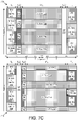
- FIG. 7A-7D depict various examples of slot resource usage for non-paired spectrum (e.g., TDD).
- each physical channel carrying DCI, UCI, DL data, or UL data may have a separate demodulation reference signal ("DM RS") 702.
- DM RS demodulation reference signal
- frequency division multiplexed (FDM) DM RS are used for demodulation of DCI and short PUCCH/PUSCH/DL data channel.
- the short PUCCH/PUSCH/DL data channels are always transmitted with an OFDM waveform.
- time division multiplexed (TDM) DM RS are used for long PUSCH, which can be transmitted with either an OFDM or DFT-S-OFDM waveform, as discussed above.
- TDM DM RS are employed for all physical channels irrespective of the waveform used.
- Figures 7A and 7B show examples of slot usage with TDM DM RS for non-paired spectrum (e.g., TDD-mode operation).
- Figures 7C and 7D show examples of slot usage with a mix of TDM and FDM DM RS for non-paired spectrum (e.g., TDD-mode operation).
- the slot duration is equal to 7 symbol durations (Ts).
- Figures 7A-7D show exemplary uses of a slot from the system perspective in non-paired spectrum.
- the slot comprises 7 OFDM (or DFT-S-OFDM) symbols with symbol duration of T s .
- 'UCI' occupying 1 symbol depicts short PUCCHs
- 'UCI' occupying more than 2 symbols corresponds to long PUCCHs.
- Short PUCCHs may be frequency division multiplexed with short UL data channels (e.g., PUSCH also occupying one or two symbol periods), long UL data channels (e.g., PUSCH occupying more than 2 symbol periods), and/or long PUCCH in the last symbol period.
- a mobile communication network may dynamically determine and signal, in slot n, radio resources (e.g., subcarrier allocation) of short PUCCH/PUSCH for slot n, considering other pre-scheduled long PUSCH/PUCCH transmission in slot n. (e.g., the UL data or a full/periodic CSI report). Dynamically adapting short PUCCH/PUSCH resources allows flexible scheduling of long PUSCH/PUCCH and enables efficient resource utilization.
- radio resources e.g., subcarrier allocation
- subcarrier allocation of short PUCCH/PUSCH for slot n can be indicated in a slot n-k which includes a DL region, is prior to but closest to slot n.
- both short PUCCH and short PUSCH resources for slot n may be dynamically signaled via DCI 625 in slot n (or in slot n-k if there is no DL region in slot n).
- the resource of short PUCCH for HARQ-ACK feedback may be indicated in DCI scheduling a corresponding DL data channel, if the DL scheduling DCI is transmitted in slot n or slot n-k.
- the network can set a guard period ("GP") 711 shorter than the symbol duration of a data channel and can exploit the remaining time of the symbol duration of the data channel, which is not reserved for the GP 711, for transmission/reception of DM RS 702 of the data channel.
- the DM RS 702 of the data channel is transmitted/received with a larger subcarrier spacing (which corresponds to shorter symbol duration) than a subcarrier spacing of the data channel.
- the DM RS 702 is further time division multiplexed with the data channel, as shown.
- the GP 711 accommodates DL-to-UL switching including hardware switching time and UL transmit timing advance (TA).
- Figure 7A illustrates a first slot usage example 700 and a second example 705 of slot usage with TDM DM RS 702.
- the slot begins with a half-symbol used for transmission of DM RS 702.
- short downlink data channels 704 and 708 are transmitted (e.g., PDSCH) and DCI 706 and 710 are transmitted (e.g., in downlink control channels, such as PDCCH), thus an example of time division multiplexing of DM RS with the downlink channels.
- the DM RS 702 transmitted in the first half-symbol are associated with downlink channels transmitted in this symbol time.
- the GP 711 is set for the following half-symbol (e.g., from 1.5 to 2.0 symbols), wherein the system transitions from downlink to uplink.
- the uplink portion of the slot begins with another half-symbol (e.g., from 2.0 to 2.5 symbols) being used for a DM RS 702.
- the DM RS 702 are associated with uplink channels transmitted over at least the next three symbols (e.g., from 2.5 to 5.5 symbols), thus an example of time division multiplexing of DM RS with the uplink channels.
- the uplink channels include long uplink control channels carrying UCI 712 and UCI 720. Note that these control channels are considered to be "long" control channels as they are longer than two symbols in duration.
- the uplink channels also include long data channels (e.g., long PUSCHs) carrying UL data 714, 716, and 718.
- the UEs transmit another DM RS 702.
- the DM RS 702 are associated with uplink channels transmitted over at least the last symbol (e.g., from 6.0 to 7.0 symbols), thus time division multiplexing of DM RS with the uplink channels.
- the UCI 712 and UCI 720 continue in the last symbol.
- the long data channel 716 continues into the last symbol of the slot.
- a first DM RS (labelled "DM RS1") is transmitted immediately following the GP 711 and a second DM RS (labelled "DM RS2”) is transmitted immediately before the last symbol of the slot.
- the first slot usage example 700 includes short control channels (e.g., short PUCCH) for UCI 722, UL data 724 and UCI 726 transmitted in the last symbol of the slot. Recall that these channels are considered "short" uplink channels because they are not more than two symbols in duration. Also note that DM RS 702 corresponding to the short uplink channels are transmitted immediately before the short PUCCH/PUSCH.
- short control channels e.g., short PUCCH
- the UL data 724 and at least one of the UCI 722 and UCI 726 are transmitted by the same UE, and thus an example of short PUCCH multiplexed with short PUSCH in the frequency domain.
- one of the UCI 712 and UCI 720 as well as at least one of the UCI 722 and UCI 726 are transmitted by the same UE, and thus an example of short PUCCH multiplexed with long PUCCH in the time and frequency domain.
- Such a UE handles the overlap of short PUCCH and long PUCCH in the last symbol of the slot as described above with reference to Figure 6 .
- the UL data 716 and at least one of the UCI 722, the UL data 724, and UCI 726 are transmitted by the same UE, and thus an example of long PUSCH multiplexed with short PUCCH and/or short PUSCH in the time and frequency domain.
- the slot again begins with a half-symbol used for transmission of DM RS 702.
- DM RS 702. In the following symbol (e.g., from 0.5 to 1.5 symbols) long downlink data channel 728 and short downlink data channel 708 are transmitted (e.g., PDSCH) and DCI 706 and 710 are transmitted, e.g., in short downlink control channels (such as PDCCH).
- the DM RS 702 transmitted in the first half-symbol are associated with the downlink channels transmitted in this symbol time, thus time division multiplexing DM RS with the downlink channels.
- Another DM RS 702 is transmitted in the following half-symbol (e.g., from 1.5 to 2.0 symbols).
- the DM RS 702 are associated with downlink data channels 728, 730, and 732 transmitted in the following three symbol periods (e.g., from 2.0 to 5.0 symbols), also time division multiplexing DM RS with the downlink channels. Note that here, that the downlink data channel 728 continues such that a second DM RS for the channel is transmitted from 1.5 to 2.0 symbols.
- the system sets a GP 711 for switching from downlink to uplink.
- the GP has a half-symbol duration (e.g., from 5.0 to 5.5 symbols).
- the uplink portion of the slot begins with another half-symbol (e.g., from 5.5 to 6.0 symbols) being used for uplink DM RS 702.
- the DM RS 702 are associated with uplink channels transmitted over the last symbol of the slot (e.g., from 6.0 to 7.0 symbols), thus time division multiplexing DM RS with the uplink channels.
- the second slot usage example 705 includes short control channels (e.g., short PUCCH) for UCI 734 and UCI 738 and a short data channel (e.g., short PUSCH) for uplink data 736.
- short control channels e.g., short PUCCH
- a short data channel e.g., short PUSCH
- uplink data 736 e.g., uplink data 736.
- DM RS 702 associated with the short uplink channels are transmitted immediately before the short PUCCH/PUSCH (and immediately following the GP 711).
- the UL data 736 and at least one of the UCI 734 and UCI 738 are transmitted by the same UE, and thus an example of short PUCCH multiplexed with short PUSCH in the frequency domain.
- Figure 7B illustrates a third example 715 and a fourth example 725 of slot usage with TDM DM RS 702.
- the depicted slots are dedicated to either uplink or downlink.
- the first two symbols are used to transmit long PUCCH/PUSCH followed by transmission of DM RS 702 over half a symbol (e.g., from 2.0 to 2.5 symbols).
- DM RS 702 transmission of the long PUCCH/PUSCH continues over the following three symbol durations (e.g., from 2.5 to 5.5 symbols), thus time division multiplexing DM RS with the uplink channels.
- another DM RS is transmitted over the next half-symbol (e.g., from 5.5 to 6.0 symbols).
- the third slot usage example 715 includes short control channels for the UCI 722 and UCI 726 and a short data channel for the uplink data 724. Further, the long control channels for the UCI 712 and UCI 720, as well as the long data channel for the uplink data 716, all continue into the last symbol of the slot.
- the same UE 205 may be assigned both one of UCI 712, UL data 716, and UCI 720 and one of the UCI 722, UL data 724, and the UCI 726, all of which overlap in time during the last symbol of the slot.
- the UE may transmit the short channel (e.g., the UCI 722, UL data 724, or the UCI 726) without transmitting the long channel (e.g., the UCI 712, UL data 716, or UCI 720) based on UE capabilities and expected waveform of the uplink channels.
- the UL data 724 and at least one of the UCI 722 and UCI 726 are transmitted by the same UE, and thus an example of short PUCCH multiplexed with short PUSCH in the frequency domain.
- one of the UCI 712 and UCI 720 as well as at least one of the UCI 722 and UCI 726 are transmitted by the same UE, and thus an example of short PUCCH multiplexed with long PUCCH in the time and frequency domain.
- Such a UE handles the overlap of short PUCCH and long PUCCH in the last symbol of the slot as described above with reference to Figure 6 .
- the UL data 716 and at least one of the UCI 722, the UL data 724, and UCI 726 are transmitted by the same UE, and thus an example of long PUSCH multiplexed with short PUCCH and/or short PUSCH in the time and frequency domain.
- the slot begins with a half-symbol used for transmission of downlink DM RS 702.
- long downlink data channel 728 and short downlink data channel 708 are transmitted (e.g., PDSCH) and DCI 706 and 710 are transmitted, e.g., in short downlink control channels (such as PDCCH), thus time division multiplexing DM RS with the downlink channels.
- the DM RS 702 transmitted in the first half-symbol are associated with at least the downlink channels transmitted in this symbol time.
- Another DM RS 702 is transmitted in the following half-symbol (e.g., from 1.5 to 2.0 symbols).
- the DM RS 702 are associated with downlink data channels 728, 730, and 732 transmitted in the following five symbol periods (e.g., from 2.0 to 7.0 symbols), thus time division multiplexing DM RS with the downlink channels.
- the downlink data channel 728 continues such that a second DM RS for the channel is transmitted from 1.5 to 2.0 symbols.
- Figure 7C illustrates a fifth example 735 and sixth example 745 of slot usage.
- the slot usage includes both TDM DM RS and FDM DM RS.
- the slot begins with a whole symbol used for transmission of short downlink channels 740-744 multiplexed with FDM DM RS. Included are the DCI + DM RS combination 740, the DL data + DM RS combination 742, and the DCI + DM RS combination 744. Note that DL data 728 (without multiplexed FDM DM RS) is also transmitted in the first symbol.
- TDM DM RS 702 is transmitted for half a symbol duration (e.g., from 1.0 to 1.5 symbols).
- the DM RS 702 transmitted here are associated with the long downlink channels transmitted in the following four symbols (e.g., from 1.5 to 5.5 symbols), thus time division multiplexing DM RS with the downlink channels.
- the DM RS 702 are associated with downlink data channels carrying the DL data 728, 746, 748, and 750 and transmitted in the following three symbol periods (e.g., from 2.0 to 5.0 symbols). Note also, that the downlink data channel 728 continues.
- the system sets a GP 711 for switching from downlink to uplink.
- the GP has a half-symbol duration (e.g., from 5.5 to 6.0 symbols).
- the uplink portion of the slot begins with the last symbol (e.g., from 6.0 to 7.0 symbols) being used for short uplink channels multiplexed with FDM DM RS.
- the UCI + DM RS combination 752 the UL data + DM RS combination 754, and the UCI + DM RS combination 756.
- the UL data + DM RS combination 754 and at least one of the UCI + DM RS combination 752 and UCI + DM RS combination 756 are transmitted by the same UE, and thus an example of short PUCCH multiplexed with short PUSCH in the frequency domain (and further multiplexed with DM RS in the frequency domain).
- the slot begins with a whole symbol used for transmission of short downlink channels 740-744 multiplexed with FDM DM RS. Included are the DCI + DM RS combination 740, the DL data + DM RS combination 742, the DCI + DM RS combination 744, and the DL data + DM RS combination 758. Note that DL data 728 (without multiplexed FDM DM RS) is also transmitted in the first symbol.
- the system sets a GP 711 for switching from downlink to uplink.
- the GP has a half-symbol duration (e.g., from 1.0 to 1.5 symbols).
- the uplink portion of the slot begins with TDM DM RS 702 being transmitted over half a symbol duration (e.g., from 1.5 to 2.0 symbols).
- the DM RS 702 transmitted here are associated with the long uplink channels transmitted in the following four symbols (e.g., from 2.0 to 6.0 symbols), thus time division multiplexing DM RS with the uplink channels.
- the DM RS 702 are associated with uplink control channels for UCI 712 and 720 and uplink data channels for UL data 714, UL data 716, and UL data 718.
- the uplink control channels for UCI 712 and UCI 720 continue to the end of the slot (e.g., continue into the last symbol).
- the sixth slot usage example 745 depicts in the last symbol (e.g., from 6.0 to 7.0 symbols) being used for short uplink channels multiplexed with FDM DM RS. Depicted here are the UCI + DM RS combination 760, the UL data + DM RS combination 762, and the UCI + DM RS combination 764.
- the UL data + DM RS combination 762 and at least one of the UCI + DM RS combination 760 and UCI + DM RS combination 764 are transmitted by the same UE, and thus an example of short PUCCH multiplexed with short PUSCH in the frequency domain (and further multiplexed with DM RS in the frequency domain).
- one of the UCI 712 and UCI 720 as well as at least one of the UCI + DM RS combination 760 and UCI + DM RS combination 764 are transmitted by the same UE, and thus an example of short PUCCH multiplexed with long PUCCH in the time domain.
- Such a UE handles the overlap of short PUCCH and long PUCCH in the last symbol of the slot as described above with reference to Figure 6 .
- the UL data 716 and at least one of the at least one of the UCI + DM RS combination 760, UL data + DM RS combination 762, and UCI + DM RS combination 764 are transmitted by the same UE, and thus an example of long PUSCH multiplexed with short PUCCH and/or short PUSCH in the time and frequency domain.
- Figure 7D illustrates a seventh example 755 and an eighth example 765 of slot usage.
- the slot usage in Figure 7D includes both FDM DM RS and TDM DM RS 702.
- the depicted slots are dedicated to either uplink or downlink.
- the slot begins with a whole symbol used for transmission of short downlink channels 740-744 multiplexed with FDM DM RS. Included are the DCI + DM RS combination 740, the DL data + DM RS combination 742, and the DCI + DM RS combination 744. Note that DL data 728 (without multiplexed FDM DM RS) is also transmitted in the first symbol.
- TDM DM RS 702 is transmitted for half a symbol duration (e.g., from 1.0 to 1.5 symbols).
- the DM RS 702 transmitted here are associated with the long downlink channels transmitted in the following four symbols (e.g., from 1.5 to 5.5 symbols), thus time division multiplexing DM RS with downlink channels.
- the DM RS 702 are associated with downlink data channels for the DL data 728, the DL data 746, the DL data 748, and the DL data 750 transmitted in the following three symbol periods (e.g., from 1.5 to 4.5 symbols). Note also, that the downlink data channel 728 continues.
- a TDM DM RS 702 is again transmitted, e.g., from 4.5 to 5.0 symbols.
- the DM RS 702 are second DM RS 702 for the downlink data channels carrying the DL data 728, the DL data 746, the DL data 748, and the DL data 750, again time division multiplexing DM RS with the data channels.
- the DL data channels then communicate the DL data 728, 746, 748, and 750 over the final two symbols of the slot.
- the slot begins with a half-symbol used for transmission of downlink DM RS 702.
- UCI 712 and 720 are transmitted on long uplink control channels and UL data 714, UL data 716, and UL data 718 are transmitted on long uplink data channels, thus time division multiplexing DM RS with the uplink channels.
- a second TDM DM RS 702 is again transmitted, e.g., from 3.5 to 4.0 symbols.
- the DM RS 702 are second DM RS 702 for the long uplink control channels and long uplink data channels, again time division multiplexing DM RS with uplink channels.
- the eighth slot usage example 765 depicts in the last symbol (e.g., from 6.0 to 7.0 symbols) being used for short uplink channels multiplexed with FDM DM RS. Depicted here are the UCI + DM RS combination 760, the UL data + DM RS combination 762, and the UCI + DM RS combination 764.
- the UL data + DM RS combination 762 and at least one of the UCI + DM RS combination 760 and UCI + DM RS combination 764 are transmitted by the same UE, and thus an example of short PUCCH multiplexed with short PUSCH in the frequency domain (and further multiplexed with DM RS in the frequency domain).
- one of the UCI 712 and UCI 720 as well as at least one of the UCI + DM RS combination 760 and UCI + DM RS combination 764 are transmitted by the same UE, and thus an example of short PUCCH multiplexed with long PUCCH in the time and frequency domain.
- Such a UE handles the overlap of short PUCCH and long PUCCH in the last symbol of the slot as described above with reference to Figure 6 .
- the UL data 716 and at least one of the UCI + DM RS combination 760, UL data + DM RS combination 762, and UCI + DM RS combination 764 are transmitted by the same UE, and thus an example of long PUSCH multiplexed with short PUCCH and/or short PUSCH in the time and frequency domain.
- a system-wide guard period of a half symbol duration may not be large enough for some UEs in a large cell, in other embodiments the following UE/network operation may be needed:
- the UE 205 If estimated/measured round trip propagation delay or the Timing Advance value signaling by the base station for a UE 205 is larger than T1 but smaller than T2 (e.g., T1 ⁇ T2), then the UE 205 skips receiving the last DL symbol and switches to a scheduled UL transmission.
- the UE 205 may set log-likely hood ratio ("LLR") information of channels bits of the skipped DL symbol to zero (e.g., puncturing).
- LLR log-likely hood ratio
- T1 is equal to the system-wide guard period of a half symbol duration
- T2 is equal to the sum of the system-wide guard period and one symbol duration.
- the UE 205 skips transmitting the first UL symbol.
- the network does not schedule the UE 205 with short PUSCH/PUCCH together with DL reception in the same a slot.
- the network assumes that UE 205 will not monitor DCI and will not receive any downlink data in that slot.
- Figure 8 depicts multi-slot scheduling between a gNB and a UE, such as the UE 205 and gNB 210.
- a DL data resource assignment e.g. a PDSCH resource assignment
- the resource assignment may be applicable to a single slot or multiple slots.
- the UE 205 may receive downlink control signal (e.g., DCI) with a resource assignment applicable to slot 0, slot 1, slot 2, and slot 3.
- DCI downlink control signal
- data sent over the multiple slots may be sent as one transport block ("TB") or media access control layer protocol data unit (“MAC PDU”) or can be sent as multiple TBs or MAC PDUs.
- TB transport block
- MAC PDU media access control layer protocol data unit
- a first resource assignment 800 includes a single TB that spans slot 0, slot 1, slot 2, and slot 3.
- a second resource assignment 805 includes a multiple TBs in the assignment that spans slot 0, slot 1, slot 2, and slot 3. While Figure 8 shows four TBs with one TB per slot, in other embodiments a resource assignment may have more or fewer TBs over the same number of time resource units ("TRUs") and the TB boundaries may or may not align with the slot boundaries.
- TRUs time resource units
- HARQ-ACK transmissions by the UE 205 in response to data reception corresponding to the DL data resource assignment may depend on whether the resource assignment is for multiple TBs or a whether it assigns a single TB.
- Figures 9A and 9B depict uplink control message timing for multi-slot scheduling between a gNB and a UE, with the UE transmitting a short-duration uplink channel.
- Figure 9A shows downlink resources 905 and uplink resources 910 for a first timing scenario 900.
- a first UE (“UE1") receives a first DL resource assignment 915 that spans slot 0 and slot 1.
- the DL resources assignment comprises multiple FRUs (frequency resource units, e.g. RBs) and multiple TRUs (Time Resource Units, e.g. slots or OFDM symbols).
- the first DL resource assignment 915 is for a single TB, despite the assignment spanning multiple slots.
- the UE1 Upon receiving the DL data in the assigned first DL resource 915, the UE1 is expected to provide HARQ-ACK feedback. Assume here that the UE1 is to use short PUCCH to transmit the HARQ-ACK feedback (or multiplex the HARQ-ACK feedback with UL data in short PUSCH). In some embodiments, the UE1 uses information implicit in the first DL resource assignment 915 to select an uplink resource for transmitting a short uplink control channel carrying the HARQ-ACK feedback.
- the UL resource used for HARQ-ACK transmission is selected based on the last assigned TRU of the TB.
- the short PUCCH/PUSCH is located in the last symbol(s) of the slot.
- the subcarriers for the short uplink control channel carrying the HARQ-ACK feedback may be selected based on the FRUs in which the UE1 receives the DL data (e.g., based on the starting RB index of the assigned RBs).
- the UE1 selects a HARQ resource 925 (e.g., from a set of possible HARQ resources) for transmitting a short uplink control channel carrying the HARQ-ACK feedback. As depicted, the UE1 transmits HARQ-ACK feedback in slot 3.
- a second UE receives a second DL resource assignment 920 that spans slot 0, slot 1, slot 2, and slot 3.
- the DL resources assignment comprises multiple FRUs (frequency resource units, e.g. RBs) and multiple TRUs (Time Resource Units, e.g. slots or OFDM symbols).
- the second DL resource assignment 920 is for multiple TBs; specifically, one TB for each slot.
- the UE2 Upon receiving the DL data in the assigned second DL resource 920, the UE2 is expected to provide HARQ-ACK feedback for each TB. Assume here that the UE2 is to use short PUCCH to transmit the HARQ-ACK feedback (or multiplex the HARQ-ACK feedback with UL data in short PUSCH). Because the resource assignment corresponds to multiple TBs, it is beneficial for the UE2 to send multiple HARQ-ACK transmissions, e.g., each corresponding to a TB. Beneficially, this reduces the latency in scheduling retransmissions for those TBs, thereby improving system performance.
- the UE2 uses information implicit in the second DL resource assignment 920 to select an uplink resource for each short uplink control channel carrying the HARQ-ACK feedback.
- the UL resource used for HARQ-ACK transmission is selected based on the last assigned TRU of each TB.
- the short PUCCH/PUSCH is located in the last symbol(s) of the slot.
- the subcarriers for the short uplink control channel carrying the HARQ-ACK feedback may be selected based on the FRUs in which the UE2 receives the DL data (e.g., based on the starting RB index of the assigned RBs).
- the UE2 selects a HARQ resource 925 (e.g., from a set of possible HARQ resources) for each TB, to be used in transmitting a short uplink control channel carrying the HARQ-ACK feedback corresponding to the TB.
- the UE2 transmits HARQ-ACK feedback for TB1 in slot 1, transmits HARQ-ACK feedback for TB2 in slot 2, transmits HARQ-ACK feedback for TB3 in slot 3, and transmits HARQ-ACK feedback for TB4 in slot 4.
- the UE1 and the UE2 both transmit HARQ-ACK in slot 3.
- there is no collision of PUCCH because the UE1 and UE2 select different uplink frequency resources due to being assigned different FRUs (e.g., different RBs) for the TBs.
- the time delay between ending slot for DL and corresponding UL HARQ-ACK transmission can vary based on the TB size and/or the transmission duration of the TB and/or timing advance restriction (e.g., such as maximum timing advance value).
- the TB1 for the UE1 is a large TB (e.g., spanning more than one slot) and so the corresponding HARQ-ACK is with longer delay than the TBs for the UE2.
- the UE1 sends HARQ-ACK feedback corresponding to its TB1 after 2 slots, while for UE2 the corresponding HARQ-ACK is sent in the immediate slot following the slot in which each individual TB ends (e.g., due to each individual TB not spanning more than one slot.
- Figure 9B depicts a second timing scenario 950 where the UE selecting a HARQ resource 925 based on implicit determination using the DL resource assignment leads to a collision 960.
- the system schedules a first DL resource 915 for the UE1 in slots 0 and 1 and schedules a second DL resource 920 for the UE2 in slots 0-3.
- the first DL resource assignment 915 and second DL resource assignment 920 occupy different RBs of the DL resources 905.
- the system schedules a third DL resource assignment 955 to a third UE ("UE3") in slot 2 and on the same RBs as the first DL resource assignment 915.
- UE3 third UE
- the UE1 determines to send its HARQ-ACK feedback in slot 3 due to being given a large TB (or a longer duration for the TB) ending in slot 1. Also, the UE3, which has a small TB ending in slot 2, determines to send its HARQ-ACK feedback in slot 3 (note that smaller TBs require less processing time and thus may have shorter HARQ-ACK latency).
- the system has multiple HARQ resources 925 for each slot; however, because the UE1 and the UE3 are assigned same FRUs (since their DL transmissions are not time overlapping), then they end up picking the same HARQ resource 925 when HARQ-ACK resource selection based only on ⁇ ending TRU on which TB is received, FRUs on which TB is received>. This is illustrated by collision 960.
- the system can preempt the collision 960 by indicating (e.g., to the UE1 and/or the UE3) a HARQ resource 925 to use for short PUCCH.
- the UE3 (and/or UE1) is configured with multiple HARQ resources 925 via higher layers (e.g., via the RRC layer).
- the third DL resource assignment 955 (and/or the first DL resource assignment 915) includes an indication of a HARQ resource 925 to use.
- the indication may be a 2-bit element where a value of '00' indicates that the UE is to use the implicitly determined HARQ resource 925, a value of '01' indicates that the UE is to use a first resource configured by higher layers, a value of '10' indicates that the UE is to use a second resource configured by higher layers, and a value of' 11' indicates that the UE is to use a third resource configured by higher layers.
- the UE3 transmits its HARQ-ACK in slot 3 based on the indication. If the UE3 doesn't receive the indication, or if it is not configured with higher layer configured resources, the UE can send its HARQ-ACK based on the implicitly determined resource.
- the indication may indicate an offset (e.g., RB index offset or HARQ resource index offset) to use when selecting the HARQ resource 925.
- Figure 10 depicts a method 1000 for transmitting a short-duration uplink channel, according to embodiments of the disclosure.
- the method 1000 is performed by an apparatus, such as the remote unit 105, the UE 205, and/or the user equipment apparatus 400.
- the method 1000 may be performed by a processor executing program code, for example, a microcontroller, a microprocessor, a CPU, a GPU, an auxiliary processing unit, a FPGA, or the like.
- the method 1000 begins and receives 1005 a downlink scheduling assignment message assigning resources for data reception of a transport block ("TB").
- TB transport block
- the TB is received in the same slot as the first uplink resource.
- the method 1000 includes identifying 1010 a set of uplink resources allocated for a first uplink channel in a slot.
- identifying 1010 includes receiving a downlink control information ("DCI") indicating the set of resources allocated for the first uplink channel.
- receiving the DCI includes receiving common DCI in a common control region of the slot.
- identifying 1010 a set of uplink resources includes receiving a higher layer message configuring a set of HARQ-ACK resources.
- the method 1000 includes determining 1015 a first uplink resource from within the set of uplink resources.
- the determination is based on one of: a resource block ("RB") index of a first assigned frequency resource unit (“FRU") of the TB, a lowest control channel element (“CCE") index of the downlink scheduling assignment message, a hybrid automatic repeat request acknowledgement (“HARQ-ACK”) feedback delay, and a HARQ-ACK resource index/offset indicated in the downlink scheduling assignment message.
- RB resource block
- FRU first assigned frequency resource unit
- CCE lowest control channel element
- HARQ-ACK hybrid automatic repeat request acknowledgement
- HARQ-ACK hybrid automatic repeat request acknowledgement
- determining 1015 a first uplink resource includes determining a time-domain resource of the first uplink resource based on at least an ending time resource unit ("TRU") of the TB. In certain embodiments, determining 1015 a first uplink resource includes identifying a HARQ-ACK resource index indicated in the downlink scheduling assignment message, wherein the HARQ-ACK resource index indicates a specific resource from a configured set of HARQ-ACK resources.
- TRU ending time resource unit
- the resources for data reception comprise multiple time resource units ("TRUs") and multiple FRUs corresponding to multiple TBs.
- determining 1015 a first uplink resource includes determining an uplink resource for each TB in response to receiving the TB.
- the TRU is a slot comprising an integer number of OFDM symbols and the FRU is a resource block comprising 12 subcarriers.
- the method 1000 includes transmitting 1020 the first uplink channel on the first uplink resource conveying at least HARQ-ACK feedback for the TB, wherein the first uplink channel comprises one or two symbols, and the method 1000 ends. Where the resources for data reception correspond to multiple TBs, then transmitting 1020 the first uplink channel includes transmitting HARQ-ACK feedback for at least one TB prior to receiving all TBs in the downlink resource assignment.
- the remote unit receives scheduling information to transmit a second uplink channel on a second uplink resource in the slot, wherein the first uplink resource and the second uplink resource at least partially overlap in the time domain.
- the second uplink resource is larger than the first uplink resource in the time domain.
- transmitting 1020 the first uplink channel on the first uplink resource includes transmitting the first uplink channel during the overlap time.
- the second uplink channel is also transmitted during the overlap time.
- the first uplink channel and second uplink channel may be intended for the same TRP.
- the first uplink channel and second uplink channel may be intended for different TRPs and the remote unit supports more than one transmit beamforming weight at a given time instance.
- the remote unit is incapable of transmitting to two TRPs simultaneously (e.g., incapable of more than one transmit beamforming weight at a given time instance) or where the first uplink channel and second uplink channel are to be transmitted with different waveforms (e.g., OFDM and DFT-S-OFDM)
- the transmitting 1020 the first uplink channel on the first uplink resource includes transmitting only the first uplink channel during the overlap time.
- transmitting 1020 the first uplink channel on the first uplink resource includes multiplexing the first uplink channel into the second uplink channel.
- transmitting 1020 the first uplink channel comprises transmitting immediately after transmitting a reference signal.
- the UE may receive the TB in a first OFDM symbol, and transition from DL-to-UL during a gap period.
- the reference signal may be transmitted immediately after the gap period in a second OFDM symbol and using a different subcarrier spacing value than used to transmit the first uplink channel.
- the first uplink channel is transmitted in a third OFDM symbol immediately following the reference signal, but using the same subcarrier spacing value as used to communicate the TB.
- the reference signal subcarrier spacing value may be an integer multiple of the subcarrier spacing value used to communicate the TB and first uplink channel.
Landscapes
- Engineering & Computer Science (AREA)
- Signal Processing (AREA)
- Computer Networks & Wireless Communication (AREA)
- Quality & Reliability (AREA)
- Mobile Radio Communication Systems (AREA)
Applications Claiming Priority (3)
| Application Number | Priority Date | Filing Date | Title |
|---|---|---|---|
| US201662418010P | 2016-11-04 | 2016-11-04 | |
| PCT/US2017/060241 WO2018085790A1 (fr) | 2016-11-04 | 2017-11-06 | Identification d'une ressource de transmission d'un premier canal de liaison montante |
| EP17804733.8A EP3504822B1 (fr) | 2016-11-04 | 2017-11-06 | Identification d'une ressource de transmission d'un premier canal de liaison montante |
Related Parent Applications (2)
| Application Number | Title | Priority Date | Filing Date |
|---|---|---|---|
| EP17804733.8A Division-Into EP3504822B1 (fr) | 2016-11-04 | 2017-11-06 | Identification d'une ressource de transmission d'un premier canal de liaison montante |
| EP17804733.8A Division EP3504822B1 (fr) | 2016-11-04 | 2017-11-06 | Identification d'une ressource de transmission d'un premier canal de liaison montante |
Publications (2)
| Publication Number | Publication Date |
|---|---|
| EP4054101A2 true EP4054101A2 (fr) | 2022-09-07 |
| EP4054101A3 EP4054101A3 (fr) | 2023-01-04 |
Family
ID=62064269
Family Applications (2)
| Application Number | Title | Priority Date | Filing Date |
|---|---|---|---|
| EP22167717.2A Pending EP4054101A3 (fr) | 2016-11-04 | 2017-11-06 | Identification d'une ressource pour la transmission d'un premier canal de liaison montante |
| EP17804733.8A Active EP3504822B1 (fr) | 2016-11-04 | 2017-11-06 | Identification d'une ressource de transmission d'un premier canal de liaison montante |
Family Applications After (1)
| Application Number | Title | Priority Date | Filing Date |
|---|---|---|---|
| EP17804733.8A Active EP3504822B1 (fr) | 2016-11-04 | 2017-11-06 | Identification d'une ressource de transmission d'un premier canal de liaison montante |
Country Status (4)
| Country | Link |
|---|---|
| US (3) | US10531479B2 (fr) |
| EP (2) | EP4054101A3 (fr) |
| CN (2) | CN109906576B (fr) |
| WO (1) | WO2018085790A1 (fr) |
Cited By (1)
| Publication number | Priority date | Publication date | Assignee | Title |
|---|---|---|---|---|
| EP4418593A1 (fr) * | 2023-02-17 | 2024-08-21 | Nokia Technologies Oy | Procédé, appareil et produit programme d'ordinateur pour un équipement utilisateur à chaîne de radiofréquences actif unique avec multiplexage temporel de point de réception multi-transmission de liaison montante |
Families Citing this family (126)
| Publication number | Priority date | Publication date | Assignee | Title |
|---|---|---|---|---|
| KR20180046358A (ko) * | 2016-10-27 | 2018-05-08 | 주식회사 케이티 | 차세대 무선 액세스망을 위한 스케줄링 방법 및 장치 |
| CN115835395B (zh) | 2016-11-04 | 2026-04-17 | 中兴通讯股份有限公司 | 一种控制信道的发送方法和装置 |
| CN108064049B (zh) * | 2016-11-08 | 2020-03-24 | 电信科学技术研究院 | 一种上行波形获取、反馈方法、终端及基站 |
| US11240785B2 (en) * | 2016-11-16 | 2022-02-01 | Kt Corporation | Method and apparatus for transmitting and receiving uplink control data in next generation wireless network |
| US11201771B2 (en) * | 2016-11-25 | 2021-12-14 | Ntt Docomo, Inc. | User terminal and radio communication method |
| CN108616998B (zh) * | 2016-12-09 | 2020-04-24 | 上海朗帛通信技术有限公司 | 一种ue和基站中的方法和设备 |
| US10425962B2 (en) * | 2016-12-14 | 2019-09-24 | Qualcomm Incorporated | PUCCH design with flexible symbol configuration |
| US10798703B2 (en) * | 2016-12-22 | 2020-10-06 | Qualcomm Incorporated | Position of uplink short burst in new radio |
| EP3516908B1 (fr) * | 2017-01-05 | 2020-11-18 | Telefonaktiebolaget LM Ericsson (PUBL) | Procédé et dispositif terminal d'adaptation d'une puissance de transmission |
| WO2018128492A1 (fr) * | 2017-01-08 | 2018-07-12 | 엘지전자 주식회사 | Procédé de transmission de signaux de liaison montante d'un terminal dans un système de communication sans fil et dispositif prenant en charge celui-ci |
| WO2018135606A1 (fr) * | 2017-01-20 | 2018-07-26 | 株式会社Nttドコモ | Terminal utilisateur et procédé de communication sans fil |
| CN108337733B (zh) * | 2017-01-20 | 2021-01-29 | 华为技术有限公司 | 一种数据传输方法及相关装置 |
| WO2018141222A1 (fr) * | 2017-02-01 | 2018-08-09 | Guangdong Oppo Mobile Telecommunications Corp., Ltd. | Procédé de communication, dispositif de réseau et terminal |
| JP2020057825A (ja) * | 2017-02-02 | 2020-04-09 | シャープ株式会社 | 基地局装置、端末装置、通信方法、および、集積回路 |
| WO2018145115A1 (fr) * | 2017-02-06 | 2018-08-09 | Intel IP Corporation | Mappage de ressources et multiplexage d'un canal de commande de liaison montante et d'un canal de données de liaison montante |
| CN108400950B (zh) * | 2017-02-06 | 2022-10-11 | 中兴通讯股份有限公司 | 上行控制的接收、发送方法、装置、基站及用户设备 |
| JP7100012B2 (ja) * | 2017-02-24 | 2022-07-12 | 株式会社Nttドコモ | 端末、無線通信方法、基地局及びシステム |
| US11218268B2 (en) * | 2017-03-23 | 2022-01-04 | Ntt Docomo, Inc. | User terminal and radio communication method |
| US10225826B2 (en) * | 2017-03-24 | 2019-03-05 | Nokia Technologies Oy | Transmission of uplink control information for multiple control channel format lengths |
| JP7035029B2 (ja) * | 2017-04-27 | 2022-03-14 | 株式会社Nttドコモ | 端末、無線通信方法、基地局及びシステム |
| US10917278B2 (en) * | 2017-04-28 | 2021-02-09 | Nokia Technologies Oy | Frequency-domain transmitters and receivers which adapt to different subcarrier spacing configurations |
| WO2018203793A1 (fr) | 2017-05-05 | 2018-11-08 | Telefonaktiebolaget Lm Ericsson (Publ) | Indication persistante de ressources d'accusé de réception |
| CN108809532A (zh) * | 2017-05-05 | 2018-11-13 | 华为技术有限公司 | 一种数据传输方法、装置和系统 |
| US10958407B2 (en) * | 2017-06-09 | 2021-03-23 | Qualcomm Incorporated | Frequency division duplexing hybrid automatic repeat request with mini-slots |
| CN116346292A (zh) * | 2017-06-16 | 2023-06-27 | 摩托罗拉移动有限责任公司 | 传递上行链路信道的方法和装置 |
| CN110945808B (zh) * | 2017-07-17 | 2022-11-22 | Lg电子株式会社 | 在无线通信系统中报告信道状态信息的方法及其设备 |
| US11251923B2 (en) * | 2017-07-31 | 2022-02-15 | Qualcomm Incorporated | Uplink ACK/NACK and SR in short durations |
| EP3665810B1 (fr) * | 2017-08-09 | 2022-10-19 | Telefonaktiebolaget LM Ericsson (Publ) | Intervalle de protection transitoire |
| WO2019032741A1 (fr) * | 2017-08-10 | 2019-02-14 | Sharp Laboratories Of America, Inc. | Structure d'intervalle de la conception de canal physique de commande de liaison montante (pucch) long pour une nouvelle radio (nr) de 5eme génération (5g) |
| US10405308B2 (en) * | 2017-08-11 | 2019-09-03 | At&T Intellectual Property I, L.P. | Facilitating forward-compatible receivers in wireless communications systems |
| US10820338B2 (en) * | 2017-09-08 | 2020-10-27 | Sharp Kabushiki Kaisha | User equipments, base stations and methods for RNTI-based PDSCH downlink slot aggregation |
| US20210184801A1 (en) * | 2017-11-15 | 2021-06-17 | Idac Holdings, Inc. | Method and apparatus for harq-ack codebook size determination and resource selection in nr |
| US11323227B2 (en) * | 2017-11-17 | 2022-05-03 | Qualcomm Incorporated | Multiplexing of physical uplink shared channel (PUSCH) and physical uplink control channel (PUCCH) in uplink short burst transmission |
| CN110034841B (zh) * | 2018-01-11 | 2021-01-12 | 华为技术有限公司 | 一种信息传输方法、装置以及计算机可读存储介质 |
| WO2019143127A1 (fr) * | 2018-01-17 | 2019-07-25 | 엘지전자 주식회사 | Procédé d'émission/réception d'informations de commande de liaison descendante et dispositif à cet effet |
| CN110166207B (zh) * | 2018-02-14 | 2021-08-27 | 华为技术有限公司 | 一种资源确定方法和装置 |
| US10779276B2 (en) | 2018-03-30 | 2020-09-15 | Apple Inc. | Self-contained slot and slot duration configuration in NR systems |
| US11290220B2 (en) * | 2018-04-06 | 2022-03-29 | Nokia Technologies Oy | Selection of physical uplink control channel resources |
| JP2021520737A (ja) * | 2018-04-06 | 2021-08-19 | ノキア テクノロジーズ オサケユイチア | ライセンスされない新無線でのアップリンク帯域幅部分切替え |
| PL3790334T3 (pl) * | 2018-05-10 | 2024-03-18 | Beijing Xiaomi Mobile Software Co., Ltd. | Sposób i urządzenie do multipleksowania przesyłania informacji oraz sposób i urządzenie do odbierania informacji |
| US10980049B2 (en) * | 2018-05-10 | 2021-04-13 | Qualcomm Incorporated | Allocating physical uplink control channel (PUCCH) resources for ultra-reliable low latency communication (URLLC) |
| KR102192826B1 (ko) * | 2018-05-10 | 2020-12-18 | 엘지전자 주식회사 | 무선 통신 시스템에서 무선 신호 송수신 방법 및 장치 |
| WO2019218134A1 (fr) | 2018-05-15 | 2019-11-21 | 南通朗恒通信技术有限公司 | Procédé et appareil utilisés dans un équipement d'utilisateur de communication sans fil et station de base |
| US11444727B2 (en) * | 2018-05-18 | 2022-09-13 | Lenovo (Beijing) Limited | Method and apparatus for HARQ-ACK payload reduction for semi-static HARQ-ACK codebook determination |
| US11064510B2 (en) * | 2018-05-30 | 2021-07-13 | Qualcomm Incorporated | Ranging between a user equipment and a fixed reference node |
| US11751159B2 (en) | 2018-05-30 | 2023-09-05 | Qualcomm Incorporated | Ranging between a user equipment and a fixed reference node |
| WO2019244221A1 (fr) * | 2018-06-18 | 2019-12-26 | 株式会社Nttドコモ | Terminal utilisateur |
| US11432369B2 (en) * | 2018-06-19 | 2022-08-30 | Apple Inc. | Reference signal and control information processing in 5G-NR wireless systems |
| US11350441B2 (en) * | 2018-06-28 | 2022-05-31 | Ntt Docomo, Inc. | User terminal |
| US10924225B2 (en) | 2018-08-03 | 2021-02-16 | Mediatek Inc. | Group-based hybrid automatic repeat request (HARQ) acknowledgement feedback |
| CN112586072B (zh) * | 2018-08-09 | 2023-09-01 | Lg 电子株式会社 | 终端在免执照频带中发送数据的方法和使用该方法的装置 |
| WO2020030976A2 (fr) * | 2018-08-09 | 2020-02-13 | Lenovo (Singapore) Pte. Ltd. | Attributions de liaison descendante pour canaux de commande de liaison descendante |
| JP7198910B2 (ja) * | 2018-08-10 | 2023-01-04 | テレフオンアクチーボラゲット エルエム エリクソン(パブル) | アップリンク送信タイミングのためのシステム及び方法 |
| KR102677346B1 (ko) | 2018-08-10 | 2024-06-20 | 지티이 코포레이션 | 제어 정보 송신 기법 |
| CN109075959B (zh) * | 2018-08-10 | 2021-10-08 | 北京小米移动软件有限公司 | 发送信息的方法、装置、存储介质以及终端 |
| CN110535583B (zh) | 2018-08-10 | 2022-05-10 | 中兴通讯股份有限公司 | 传输确定方法、装置、基站、终端及计算机可读存储介质 |
| WO2020051735A1 (fr) * | 2018-09-10 | 2020-03-19 | Oppo广东移动通信有限公司 | Procédé de communication, dispositif terminal, et dispositif de réseau |
| CN112740784A (zh) * | 2018-09-17 | 2021-04-30 | Oppo广东移动通信有限公司 | 一种反馈时序的确定方法、终端设备及网络设备 |
| US12120060B2 (en) * | 2018-09-19 | 2024-10-15 | Qualcomm Incorporated | Acknowledgement codebook design for multiple transmission reception points |
| US20200106569A1 (en) | 2018-09-27 | 2020-04-02 | Mediatek Inc. | Mechanisms for postponing hybrid automatic repeat request acknowledgement (harq-ack) feedback |
| WO2020062081A1 (fr) * | 2018-09-28 | 2020-04-02 | 华为技术有限公司 | Procédé de transmission de données, dispositif terminal, et dispositif de réseau |
| CN111148265B (zh) * | 2018-11-02 | 2023-05-23 | 中兴通讯股份有限公司 | 下行控制信息传输方法及装置 |
| WO2020034430A1 (fr) | 2018-11-02 | 2020-02-20 | Zte Corporation | Techniques de communication cellulaire fiable |
| US11296849B2 (en) * | 2018-11-02 | 2022-04-05 | Lenovo (Singapore) Pte. Ltd. | Method and apparatus for transmitting HARQ-ACK information |
| KR20200063008A (ko) | 2018-11-27 | 2020-06-04 | 삼성전자주식회사 | 무선 통신 시스템에서 harq-ack 피드백을 송수신하는 방법 및 장치 |
| CN111356213B (zh) * | 2018-12-20 | 2021-07-13 | 大唐移动通信设备有限公司 | 一种信息传输方法、基站及终端 |
| WO2020144540A1 (fr) | 2019-01-10 | 2020-07-16 | Lenovo (Singapore) Pte. Ltd. | Commande de puissance de liaison montante |
| CN113302890B (zh) | 2019-01-10 | 2024-03-01 | 苹果公司 | 用于在高于52.6千兆赫(ghz)载波频率下操作的系统的参考信号设计 |
| US11277854B2 (en) * | 2019-01-22 | 2022-03-15 | T-Mobile Usa, Inc. | Systems and methods to enhance spectrum efficiency and to reduce latency by using dynamic guard time selection in wireless systems |
| CN113711520B (zh) * | 2019-02-15 | 2024-10-29 | 瑞典爱立信有限公司 | 低延迟通信的harq码本确定的方法 |
| CN111586843B (zh) * | 2019-02-15 | 2023-04-07 | 上海朗帛通信技术有限公司 | 被用于无线通信的用户设备、基站中的方法和装置 |
| SG11202109985UA (en) * | 2019-03-11 | 2021-10-28 | Beijing Xiaomi Mobile Software Co Ltd | Transmission indication method and apparatus |
| CN111757487B (zh) | 2019-03-29 | 2022-04-12 | 华为技术有限公司 | 一种通信方法及设备 |
| CN114124331B (zh) * | 2019-03-30 | 2023-09-26 | 华为技术有限公司 | 通信方法、通信装置和系统 |
| WO2020211951A1 (fr) * | 2019-04-18 | 2020-10-22 | Huawei Technologies Co., Ltd. | Dispositifs et procédés permettant d'augmenter la capacité de planification pour une communication bidirectionnelle dans un système 5g |
| JP2022533336A (ja) * | 2019-05-13 | 2022-07-22 | テレフオンアクチーボラゲット エルエム エリクソン(パブル) | アップリンク送信のための方法、端末デバイス、およびネットワークノード |
| CN114026938A (zh) * | 2019-06-26 | 2022-02-08 | 索尼集团公司 | 通信设备及通信方法 |
| CN112567845A (zh) | 2019-07-26 | 2021-03-26 | Oppo广东移动通信有限公司 | 无线通信方法和设备 |
| EP3993535B1 (fr) | 2019-07-31 | 2025-02-26 | Guangdong Oppo Mobile Telecommunications Corp., Ltd. | Multiplexage de transmission pucch chevauchante |
| CN114175825B (zh) * | 2019-08-01 | 2025-02-25 | 高通股份有限公司 | 用于基于全双工的iab的上行链路抢占指示 |
| US12206622B2 (en) * | 2019-08-01 | 2025-01-21 | Lenovo (Beijing) Limited | Apparatus and method of harq-ack feedback |
| CN111835481B (zh) * | 2019-08-02 | 2023-07-25 | 维沃移动通信有限公司 | 上行传输方法、终端和网络侧设备 |
| WO2021026701A1 (fr) * | 2019-08-09 | 2021-02-18 | Oppo广东移动通信有限公司 | Procédé de transmission de données, dispositif de réseau et équipement utilisateur |
| PH12022550210A1 (en) * | 2019-08-12 | 2022-12-12 | Ericsson Telefon Ab L M | Transmission of uplink control information with colliding pusch |
| CN114208248B (zh) * | 2019-08-14 | 2024-09-17 | 株式会社Ntt都科摩 | 终端以及通信方法 |
| WO2021029052A1 (fr) * | 2019-08-14 | 2021-02-18 | 株式会社Nttドコモ | Terminal et procédé de communication |
| US12245224B2 (en) * | 2019-08-23 | 2025-03-04 | Lg Electronics Inc. | Method for transmitting or receiving uplink channel in wireless communication system, and device therefor |
| CN112564865B (zh) * | 2019-09-26 | 2024-04-02 | 株式会社Kt | 用于发送和接收侧链harq反馈信息的方法和装置 |
| US12513724B2 (en) * | 2019-09-27 | 2025-12-30 | Qualcomm Incorporated | Physical downlink control channel resources for reduced capability user equipment |
| EP4030843B1 (fr) * | 2019-11-06 | 2024-04-03 | Guangdong Oppo Mobile Telecommunications Corp., Ltd. | Procédé de traitement pour des ressources fragmentées et dispositif de traitement |
| CA3157199A1 (fr) | 2019-11-08 | 2021-05-14 | Huawei Technologies Co., Ltd. | Procede et appareil de determination de ressources |
| WO2021090298A1 (fr) * | 2019-11-08 | 2021-05-14 | Lenovo (Singapore) Pte. Ltd. | Procédé et appareil de gestion de la transmission d'un message de rétroaction |
| CN112839380B (zh) * | 2019-11-22 | 2024-11-19 | 北京三星通信技术研究有限公司 | 发送上行链路信号的方法和设备 |
| US11575488B2 (en) * | 2019-12-13 | 2023-02-07 | Qualcomm Incorporated | Coverage enhancement for a beam change acknowledgement |
| KR20210128477A (ko) * | 2019-12-31 | 2021-10-26 | 지티이 코포레이션 | 취소를 표시하는 정보를 결정하기 위한 시스템 및 방법 |
| WO2021155502A1 (fr) * | 2020-02-05 | 2021-08-12 | Qualcomm Incorporated | Multiplexage d'uci sur un pusch permettant une transmission en liaison montante à panneaux multiples |
| CN115004602B (zh) * | 2020-02-19 | 2026-02-03 | 中兴通讯股份有限公司 | 用于确定下行链路控制信息的系统和方法 |
| US11611983B2 (en) * | 2020-02-20 | 2023-03-21 | Qualcomm Incorporated | Acknowledgement feedback for multi-component carrier scheduling |
| US12328730B2 (en) | 2020-03-04 | 2025-06-10 | Qualcomm Incorporated | Multiplexing for physical uplink channels with different directional beams |
| EP4118919A1 (fr) * | 2020-03-11 | 2023-01-18 | Lenovo (Singapore) Pte. Ltd. | Commutation de faisceau après avoir réalisé une porteuse avant émission |
| WO2021197759A1 (fr) * | 2020-03-31 | 2021-10-07 | Sony Group Corporation | Procédés et dispositifs de communication |
| US11758513B2 (en) * | 2020-04-20 | 2023-09-12 | Qualcomm Incorporated | Physical uplink control channel with uplink message short data field |
| US11523301B2 (en) | 2020-04-20 | 2022-12-06 | Qualcomm Incorporated | Physical uplink control channel with buffer status report |
| EP4140212B1 (fr) * | 2020-04-21 | 2024-10-16 | Qualcomm Incorporated | Techniques de répétition d'un bloc de transport au moyen d'un multiplexage par répartition spatiale |
| US11546935B2 (en) * | 2020-04-29 | 2023-01-03 | Qualcomm Incorporated | Feedback for multiple downlink transmissions |
| US11871408B2 (en) * | 2020-06-16 | 2024-01-09 | Qualcomm Incorporated | Physical uplink control channel repetition across slot types |
| WO2021253456A1 (fr) * | 2020-06-20 | 2021-12-23 | Qualcomm Incorporated | Alignement de durées pour répétitions d'un canal physique partagé lors de transmissions à panneaux multiples |
| US11838910B2 (en) * | 2020-06-22 | 2023-12-05 | Qualcomm Incorporated | Techniques for dynamic scheduling of reverse sidelink traffic |
| US20230284190A1 (en) * | 2020-06-29 | 2023-09-07 | Lenovo (Singapore) Pte. Ltd. | Control information that schedules or activates multiple transmissions |
| WO2022006833A1 (fr) * | 2020-07-10 | 2022-01-13 | Qualcomm Incorporated | Multiplexage d'informations de commande de liaison montante pour de multiples panneaux |
| US12028856B2 (en) * | 2020-07-23 | 2024-07-02 | Ofinno, Llc | Feedback transmission with multiple transmission reception points |
| EP4189896A4 (fr) * | 2020-08-03 | 2024-05-01 | Qualcomm Incorporated | Priorisation de communications de liaison montante par l'intermédiaire de multiples panneaux d'antenne |
| US11805542B2 (en) * | 2020-09-15 | 2023-10-31 | Acer Incorporated | Method used by UE to multiplex uplink transmissions and UE using the same |
| WO2022067641A1 (fr) * | 2020-09-30 | 2022-04-07 | Lenovo (Beijing) Limited | Procédé et appareil pour l'ordonnancement et la transmission dans les sens montant et descendant |
| CN116349337A (zh) * | 2020-10-12 | 2023-06-27 | Oppo广东移动通信有限公司 | 资源调度方法、终端设备和网络设备 |
| WO2022077295A1 (fr) * | 2020-10-14 | 2022-04-21 | 北京小米移动软件有限公司 | Procédé et appareil de planification conjointe de multiples blocs de transport, dispositif de communication et support d'enregistrement |
| CN116491079A (zh) * | 2020-10-22 | 2023-07-25 | 联想(新加坡)私人有限公司 | 包括涉及中继实体的多个线路的通信路径的上行链路定时维护 |
| US11570764B2 (en) * | 2020-12-04 | 2023-01-31 | Qualcomm Incorporated | FD mode dependent UCI multiplexing |
| CN113055948B (zh) * | 2021-03-17 | 2022-06-07 | 中国联合网络通信集团有限公司 | 一种下行资源块预留方法和装置 |
| US12356203B2 (en) * | 2021-05-25 | 2025-07-08 | Ani Acquisition Sub, Llc | Dynamic network resource management in a wireless communications system (WCS) |
| CN113316265B (zh) * | 2021-06-11 | 2023-09-01 | Oppo广东移动通信有限公司 | 上行调度任务处理方法、终端设备、存储介质及芯片 |
| WO2023282805A1 (fr) * | 2021-07-08 | 2023-01-12 | Telefonaktiebolaget Lm Ericsson (Publ) | Premier nœud, second nœud et procédés réalisés par ceux-ci pour envoyer une attribution à un dispositif sans fil compris dans un trajet à sauts multiples comportant une pluralité de nœuds relais |
| CN115022971B (zh) * | 2022-05-30 | 2024-05-28 | 南通领讯信息技术有限公司 | 一种无线通信方法及使用该方法的基站 |
| CN117395731A (zh) * | 2022-06-29 | 2024-01-12 | 上海朗帛通信技术有限公司 | 一种用于无线通信的节点中的方法和装置 |
| US20260082347A1 (en) * | 2022-09-23 | 2026-03-19 | Apple Inc. | Systems, methods, and apparatuses for enabling multiple timing advances for multiple transmission reception points in wireless communication |
| US12547784B2 (en) * | 2023-03-06 | 2026-02-10 | Dell Products, L.P. | Systems and methods to represent functions in a PCIe multi-function field replaceable unit |
Citations (1)
| Publication number | Priority date | Publication date | Assignee | Title |
|---|---|---|---|---|
| EP3399818A1 (fr) * | 2016-02-01 | 2018-11-07 | Huawei Technologies Co., Ltd. | Procédé et appareil de transmission d'informations de commande de liaison montante |
Family Cites Families (21)
| Publication number | Priority date | Publication date | Assignee | Title |
|---|---|---|---|---|
| US9084277B2 (en) | 2007-05-04 | 2015-07-14 | Qualcomm Incorporated | Method and apparatus for UL ACK allocation |
| US9036564B2 (en) * | 2008-03-28 | 2015-05-19 | Qualcomm Incorporated | Dynamic assignment of ACK resource in a wireless communication system |
| WO2011158921A1 (fr) * | 2010-06-14 | 2011-12-22 | Sharp Kabushiki Kaisha | Equipement utilisateur, appareil de station de base, système de communication et procédés de communication mobile pour des informations de commande de liaison montante |
| EP2583519A4 (fr) * | 2010-06-18 | 2015-03-25 | Blackberry Ltd | Système et procédé pour la transmission d'informations de commande de liaison montante dans un assemblage de porteuses |
| US8891348B2 (en) * | 2010-09-15 | 2014-11-18 | Lg Electronics Inc. | Method and apparatus for transmitting control information |
| CN104685955B (zh) * | 2012-09-28 | 2019-02-01 | Lg电子株式会社 | 上行链路传输方法和上行链路传输装置 |
| US9451466B2 (en) * | 2013-03-15 | 2016-09-20 | Qualcomm Incorporated | Base station employing shared resources among antenna units |
| CN105981324B (zh) * | 2014-02-08 | 2019-08-09 | Lg电子株式会社 | 用于在支持无线资源的使用的变化的无线通信系统中发送回退模式的上行链路信号的方法及其设备 |
| EP3195689B1 (fr) * | 2014-09-19 | 2019-02-06 | Telefonaktiebolaget LM Ericsson (publ) | Procédé de libération sps de liaison montante |
| US10396873B2 (en) * | 2014-09-24 | 2019-08-27 | Mediatek Inc. | Control signaling in a beamforming system |
| WO2016053047A1 (fr) * | 2014-10-02 | 2016-04-07 | 엘지전자 주식회사 | Procédé et équipement d'utilisateur pour émettre un signal de liaison montante, ainsi que procédé et équipement d'utilisateur pour recevoir un signal de liaison montante |
| US20160205540A1 (en) * | 2015-01-09 | 2016-07-14 | Htc Corporation | Methods of handling wireless communications for communication system |
| FI3251245T3 (fi) * | 2015-01-28 | 2023-06-20 | Interdigital Patent Holdings Inc | Nousevan siirtotien palautemenetelmät suuren lukumäärän kantoaaltoja kanssa toimimiseksi |
| AR103887A1 (es) * | 2015-03-09 | 2017-06-14 | ERICSSON TELEFON AB L M (publ) | Canal pucch breve en canal spucch de enlace ascendente |
| US10015778B2 (en) * | 2015-03-17 | 2018-07-03 | Telefonaktiebolaget Lm Ericsson (Publ) | Systems and methods for uplink control information signaling design |
| WO2016162090A1 (fr) * | 2015-04-10 | 2016-10-13 | Nokia Solutions And Networks Oy | Agrégation de porteuses améliorée dans des communications |
| US10021686B1 (en) * | 2015-10-19 | 2018-07-10 | Sprint Spectrum L.P. | Scheduling traffic based on acknowledgment bundling |
| US10200162B2 (en) * | 2016-05-27 | 2019-02-05 | Qualcomm Incorporated | HARQ feedback in shared RF spectrum band |
| US10531452B2 (en) * | 2016-07-11 | 2020-01-07 | Qualcomm Incorporated | Hybrid automatic repeat request feedback and multiple transmission time interval scheduling |
| US20180110042A1 (en) * | 2016-10-13 | 2018-04-19 | Qualcomm Incorporated | Concurrent transmission of low latency and non-low latency uplink control channels |
| US10856317B2 (en) * | 2016-11-17 | 2020-12-01 | Huawei Technologies Co., Ltd. | System and method for uplink communications |
-
2017
- 2017-11-06 EP EP22167717.2A patent/EP4054101A3/fr active Pending
- 2017-11-06 EP EP17804733.8A patent/EP3504822B1/fr active Active
- 2017-11-06 US US15/804,947 patent/US10531479B2/en active Active
- 2017-11-06 CN CN201780067831.2A patent/CN109906576B/zh active Active
- 2017-11-06 WO PCT/US2017/060241 patent/WO2018085790A1/fr not_active Ceased
- 2017-11-06 CN CN202210496752.6A patent/CN114826499B/zh active Active
-
2019
- 2019-12-18 US US16/719,524 patent/US11153896B2/en active Active
-
2021
- 2021-10-18 US US17/504,371 patent/US12408163B2/en active Active
Patent Citations (1)
| Publication number | Priority date | Publication date | Assignee | Title |
|---|---|---|---|---|
| EP3399818A1 (fr) * | 2016-02-01 | 2018-11-07 | Huawei Technologies Co., Ltd. | Procédé et appareil de transmission d'informations de commande de liaison montante |
Non-Patent Citations (1)
| Title |
|---|
| INTEL CORPORATION: "On CSI measurements and UCI feedback for MTC", vol. RAN WG1, no. Beijing, China; 20150824 - 20150828, 15 August 2015 (2015-08-15), XP050993884, Retrieved from the Internet <URL:http://www.3gpp.org/ftp/tsg_ran/WG1_RL1/TSGR1_82/Docs/> [retrieved on 20150815] * |
Cited By (1)
| Publication number | Priority date | Publication date | Assignee | Title |
|---|---|---|---|---|
| EP4418593A1 (fr) * | 2023-02-17 | 2024-08-21 | Nokia Technologies Oy | Procédé, appareil et produit programme d'ordinateur pour un équipement utilisateur à chaîne de radiofréquences actif unique avec multiplexage temporel de point de réception multi-transmission de liaison montante |
Also Published As
| Publication number | Publication date |
|---|---|
| US20200128576A1 (en) | 2020-04-23 |
| US10531479B2 (en) | 2020-01-07 |
| US12408163B2 (en) | 2025-09-02 |
| US11153896B2 (en) | 2021-10-19 |
| CN114826499B (zh) | 2024-11-19 |
| EP3504822B1 (fr) | 2022-05-18 |
| US20180132264A1 (en) | 2018-05-10 |
| EP4054101A3 (fr) | 2023-01-04 |
| CN109906576A (zh) | 2019-06-18 |
| WO2018085790A1 (fr) | 2018-05-11 |
| CN114826499A (zh) | 2022-07-29 |
| EP3504822A1 (fr) | 2019-07-03 |
| CN109906576B (zh) | 2022-05-24 |
| US20220046675A1 (en) | 2022-02-10 |
Similar Documents
| Publication | Publication Date | Title |
|---|---|---|
| US12408163B2 (en) | Identifying a resource for transmitting a first uplink channel | |
| US20250219769A1 (en) | Harq-ack feedback timing for sps pdsch | |
| US11696255B2 (en) | Receiving a paging message | |
| US11425697B2 (en) | Dynamic management of uplink control signaling resources in wireless network | |
| US10708872B2 (en) | Power headroom report generation | |
| US11303416B2 (en) | HARQ process aggregation of multiple scheduled slots | |
| JP6082121B2 (ja) | 情報送信方法、ユーザ装置及び基地局 | |
| US20180324786A1 (en) | Resource determination for uplink control channel for wireless networks | |
| US20230180266A1 (en) | Method and apparatus for determining non-preferred resource in wireless communication system | |
| WO2018170916A1 (fr) | Indication de format pucch et attribution de ressources | |
| WO2023015553A1 (fr) | Procédés et appareil de détermination de type de transmission ul | |
| HK40033338A (en) | Dynamic management of uplink control signaling resources in wireless network | |
| HK40033338B (en) | Dynamic management of uplink control signaling resources in wireless network |
Legal Events
| Date | Code | Title | Description |
|---|---|---|---|
| PUAI | Public reference made under article 153(3) epc to a published international application that has entered the european phase |
Free format text: ORIGINAL CODE: 0009012 |
|
| STAA | Information on the status of an ep patent application or granted ep patent |
Free format text: STATUS: THE APPLICATION HAS BEEN PUBLISHED |
|
| AC | Divisional application: reference to earlier application |
Ref document number: 3504822 Country of ref document: EP Kind code of ref document: P |
|
| AK | Designated contracting states |
Kind code of ref document: A2 Designated state(s): AL AT BE BG CH CY CZ DE DK EE ES FI FR GB GR HR HU IE IS IT LI LT LU LV MC MK MT NL NO PL PT RO RS SE SI SK SM TR |
|
| PUAL | Search report despatched |
Free format text: ORIGINAL CODE: 0009013 |
|
| AK | Designated contracting states |
Kind code of ref document: A3 Designated state(s): AL AT BE BG CH CY CZ DE DK EE ES FI FR GB GR HR HU IE IS IT LI LT LU LV MC MK MT NL NO PL PT RO RS SE SI SK SM TR |
|
| RIC1 | Information provided on ipc code assigned before grant |
Ipc: H04B 7/0408 20170101ALI20221201BHEP Ipc: H04B 7/06 20060101ALI20221201BHEP Ipc: H04B 7/0404 20170101ALI20221201BHEP Ipc: H04L 5/00 20060101ALI20221201BHEP Ipc: H04L 1/18 20060101AFI20221201BHEP |
|
| STAA | Information on the status of an ep patent application or granted ep patent |
Free format text: STATUS: REQUEST FOR EXAMINATION WAS MADE |
|
| 17P | Request for examination filed |
Effective date: 20230629 |
|
| RBV | Designated contracting states (corrected) |
Designated state(s): AL AT BE BG CH CY CZ DE DK EE ES FI FR GB GR HR HU IE IS IT LI LT LU LV MC MK MT NL NO PL PT RO RS SE SI SK SM TR |
|
| STAA | Information on the status of an ep patent application or granted ep patent |
Free format text: STATUS: EXAMINATION IS IN PROGRESS |
|
| 17Q | First examination report despatched |
Effective date: 20260108 |