EP4054217B1 - Fahrzeug mit fahrzeugnetzwerk - Google Patents
Fahrzeug mit fahrzeugnetzwerk Download PDFInfo
- Publication number
- EP4054217B1 EP4054217B1 EP21160633.0A EP21160633A EP4054217B1 EP 4054217 B1 EP4054217 B1 EP 4054217B1 EP 21160633 A EP21160633 A EP 21160633A EP 4054217 B1 EP4054217 B1 EP 4054217B1
- Authority
- EP
- European Patent Office
- Prior art keywords
- vehicle
- wireless
- network
- commercial vehicle
- wireless nodes
- Prior art date
- Legal status (The legal status is an assumption and is not a legal conclusion. Google has not performed a legal analysis and makes no representation as to the accuracy of the status listed.)
- Active
Links
Images


Classifications
-
- B—PERFORMING OPERATIONS; TRANSPORTING
- B60—VEHICLES IN GENERAL
- B60R—VEHICLES, VEHICLE FITTINGS, OR VEHICLE PARTS, NOT OTHERWISE PROVIDED FOR
- B60R16/00—Electric or fluid circuits specially adapted for vehicles and not otherwise provided for; Arrangement of elements of electric or fluid circuits specially adapted for vehicles and not otherwise provided for
- B60R16/02—Electric or fluid circuits specially adapted for vehicles and not otherwise provided for; Arrangement of elements of electric or fluid circuits specially adapted for vehicles and not otherwise provided for electric constitutive elements
- B60R16/023—Electric or fluid circuits specially adapted for vehicles and not otherwise provided for; Arrangement of elements of electric or fluid circuits specially adapted for vehicles and not otherwise provided for electric constitutive elements for transmission of signals between vehicle parts or subsystems
- B60R16/0231—Circuits relating to the driving or the functioning of the vehicle
-
- H—ELECTRICITY
- H04—ELECTRIC COMMUNICATION TECHNIQUE
- H04W—WIRELESS COMMUNICATION NETWORKS
- H04W4/00—Services specially adapted for wireless communication networks; Facilities therefor
- H04W4/30—Services specially adapted for particular environments, situations or purposes
- H04W4/40—Services specially adapted for particular environments, situations or purposes for vehicles, e.g. vehicle-to-pedestrians [V2P]
-
- H—ELECTRICITY
- H04—ELECTRIC COMMUNICATION TECHNIQUE
- H04W—WIRELESS COMMUNICATION NETWORKS
- H04W4/00—Services specially adapted for wireless communication networks; Facilities therefor
- H04W4/30—Services specially adapted for particular environments, situations or purposes
- H04W4/38—Services specially adapted for particular environments, situations or purposes for collecting sensor information
-
- G—PHYSICS
- G08—SIGNALLING
- G08C—TRANSMISSION SYSTEMS FOR MEASURED VALUES, CONTROL OR SIMILAR SIGNALS
- G08C17/00—Arrangements for transmitting signals characterised by the use of a wireless electrical link
- G08C17/02—Arrangements for transmitting signals characterised by the use of a wireless electrical link using a radio link
-
- H—ELECTRICITY
- H04—ELECTRIC COMMUNICATION TECHNIQUE
- H04W—WIRELESS COMMUNICATION NETWORKS
- H04W4/00—Services specially adapted for wireless communication networks; Facilities therefor
- H04W4/30—Services specially adapted for particular environments, situations or purposes
- H04W4/40—Services specially adapted for particular environments, situations or purposes for vehicles, e.g. vehicle-to-pedestrians [V2P]
- H04W4/46—Services specially adapted for particular environments, situations or purposes for vehicles, e.g. vehicle-to-pedestrians [V2P] for vehicle-to-vehicle communication [V2V]
-
- H—ELECTRICITY
- H04—ELECTRIC COMMUNICATION TECHNIQUE
- H04W—WIRELESS COMMUNICATION NETWORKS
- H04W4/00—Services specially adapted for wireless communication networks; Facilities therefor
- H04W4/30—Services specially adapted for particular environments, situations or purposes
- H04W4/40—Services specially adapted for particular environments, situations or purposes for vehicles, e.g. vehicle-to-pedestrians [V2P]
- H04W4/48—Services specially adapted for particular environments, situations or purposes for vehicles, e.g. vehicle-to-pedestrians [V2P] for in-vehicle communication
-
- H—ELECTRICITY
- H04—ELECTRIC COMMUNICATION TECHNIQUE
- H04L—TRANSMISSION OF DIGITAL INFORMATION, e.g. TELEGRAPHIC COMMUNICATION
- H04L67/00—Network arrangements or protocols for supporting network services or applications
- H04L67/01—Protocols
- H04L67/12—Protocols specially adapted for proprietary or special-purpose networking environments, e.g. medical networks, sensor networks, networks in vehicles or remote metering networks
-
- H—ELECTRICITY
- H04—ELECTRIC COMMUNICATION TECHNIQUE
- H04W—WIRELESS COMMUNICATION NETWORKS
- H04W84/00—Network topologies
- H04W84/005—Moving wireless networks
Definitions
- the present disclosure relates to the field of vehicular information and communication technology.
- it proposes methods and devices for establishing a data network in a vehicle or across coupled vehicle units in a combination vehicle.
- the sensors are provided with radio interfaces designed to cooperate with a corresponding radio interface of a wireless sensor gateway (WSGW) connected to a vehicle network that asses the sensor information on to the driver cab, the central vehicle computer, or towards the back-office location.
- WSGW wireless sensor gateway
- the variable geometry of vehicles and combination vehicles in particular may mean that standard network components cannot be used with their factory settings. Additionally, some metallic parts of the chassis and vehicle body may inconveniently shield, reflect or absorb radio-frequency waves.
- US2008114502A1 discloses a system for obtaining information about a vehicle or a component therein including sensors, which are fixed to a frame of the vehicle and arranged to transmit a signal upon detection of a radio frequency (RF) signal, and a directional antenna array. Each antenna element is directed toward a respective sensor, and it transmits RF signals toward that sensor and receives return signals therefrom.
- RF radio frequency
- US2020280827A1 discloses a system for V2X communications using multiple radio access technologies (RATs).
- a device includes a transceiver interface with multiple connections to communicate with multiple transceiver chains, which are configured to support multiple RATs.
- the transceiver chains can be controlled via the multiple connections of the transceiver interface to coordinate the multiple RATs to complete the communication.
- DE102010064086A1 discloses a vehicle antenna system for V2X communications, which comprises antennas that can be integrated into vehicle components.
- US2020266850A1 discloses an external wireless connection which may be provided by external antenna(s) coupled to the exterior of a vehicle, or by internal antennas within the interior of the vehicle.
- the external wireless connection may be configured to provide wireless connectivity to various external devices.
- an antenna switching network configured to control the antennas of the vehicle to provide both external and internal wireless coverage.
- One objective of the present disclosure is to make available wireless vehicle network technology that is less affected by the problems reviewed above.
- a particular objective is to propose vehicle network infrastructure that lends itself to mounting in a wide range of vehicle geometries.
- Another objective is to propose vehicle network infrastructure that overcomes the shielding, reflection and/or absorption problem. It is finally an objective to utilize the vehicle network to supply devices in the vehicle's vicinity with Internet connectivity.
- the vehicle network in the commercial vehicle is formed by mostly surface-mounted infrastructure and thereby evades problems related to electromagnetic shielding, reflection or absorption.
- the vehicle surface furthermore offers a multitude of potential mounting points, so that near-ideal spacing of the wireless nodes can be achieved relatively easily.
- the surface-mounted infrastructure, from which the vehicle network is formed has an advantageous further use as a wireless access point for the benefit of mobile stations in the vehicle's vicinity. No comparable synergy would have been available in a wireless vehicle network where the radio links extend inside the vehicle body or where the wireless nodes are otherwise out of reach of external transceivers.
- the wireless nodes have different spatial transmit/receive patterns. Some wireless nodes may be equipped with directional antennas while others may have wide-angle antennas, as is deemed most suitable in the respective mounting locations. This economizes transmit power and keeps the received signals reasonably free from noise and interference.
- the wireless nodes may operate in the gigahertz range, such as at least 1 GHz, at least 5 GHz, at least 10 GHz, at least 30 GHz or at least 50 GHz.
- This frequency range achieves different degrees of intrinsic directivity, and it includes both unlicensed and licensable spectrum.
- At least one of the wireless nodes comprises a so-called intelligent antenna module (or radio-integrated antenna, or antenna-integrated transceiver, or integrated antenna module), which for purposes of the present disclosure signifies that the baseband circuitry is co-located with the antenna element(s), without a wired connection therebetween.
- intelligent antenna module or radio-integrated antenna, or antenna-integrated transceiver, or integrated antenna module
- the baseband circuitry is co-located with the antenna element(s), without a wired connection therebetween.
- the use of smart antenna modules enables a future migration from the low gigahertz frequency range to tens of gigahertz (e.g., 28-30 GHz) without massive energy losses.
- a carrier signal that travels in a coaxial cable of feasible outer dimensions is known to suffer significant attenuation at high frequency.
- At least one of the wireless nodes is physically integrated into a projecting part of the vehicle body, to be exemplified below.
- Such integration whereby the wireless node is surrounded by free space to a greater extent, is likely to improve the transmit and receive angles under which it communicates with adjacent wireless nodes, and it may also be helpful to achieve unobscured lines of sight.
- the vehicle network has mesh-like topology.
- a mesh topology may include that multiple paths exist between a pair of nodes and/or that the nodes are not in a mutually hierarchic relation.
- the use of a mesh topology may render the vehicle network more robust to temporary breakdown of links and less error-prone on a system level.
- the wireless node acting as an access point is configured to provide Internet connectivity to sensors (including various Internet-of-Things devices with sensing capabilities), other vehicles and/or handheld devices. By sharing its Internet connectivity with these categories of devices, especially if they are located in areas outside cellular coverage, the commercial vehicle supplies a useful commodity that may add mutual value.
- a further aspect not covered by the claimed invention relates to a plurality of wireless nodes.
- the wireless nodes are suitable to be fixed to points on the surface of a vehicle and configured to cooperate to form a vehicle network, wherein lines of sights between adjacent ones of the wireless nodes are sensibly unobstructed and/or sensibly parallel to the surface of the vehicle.
- the vehicle network to be formed includes a backhaul port configured to provide Internet connectivity, at least intermittently, to the vehicle network.
- At least one of the wireless nodes is operable to act as wireless access point for mobile stations in the vehicle's vicinity.
- the shape of the vehicle may be simplified or idealized, e.g., into a cuboid constituting a bounding box.
- Internet connectivity refers to the global Internet.
- the wireless nodes connecting to the wireless access point on the commercial vehicle shall be able to exchange communications with parties other than processors in the vehicle network itself. Accordingly, the mere ability of a sensor to forward data to a central vehicle computer via a nearby WSGW does not constitute "Internet connectivity" in the intended sense. Importantly, the exchange of communications must not proceed in real time, but the vehicle network may buffer inbound communications until it has regained coverage, and it may buffer outbound communications destined to the mobile stations while these are too distant.
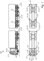
- the upper part of figure 1 is a side view of two vehicle units which can be coupled, e.g., using a drawbar, to form a combination vehicle 100.
- the vehicle units are equipped with multiple wireless nodes 21, 22, 23 operable to form a vehicle network across the full combination vehicle 100.
- Each wireless node may be configured to function as a wireless sensor gateway (WSGW) 22 for collecting measurement data from sensors in its vicinity, an ad hoc network access point 23 operable to serve mobile stations in the vicinity of the vehicle 100, an infrastructure node 21 or - as indicated by the use of multiple drawing references in figure 1 - to fulfil a combination of these roles.
- WSGW wireless sensor gateway
- an infrastructure node 21 While a WSGW 22 and an access point 23 are each configured to interface with external transceivers, the main function of an infrastructure node 21 is to maintain data links within the vehicle network, i.e., between itself and adjacent infrastructure nodes 21.
- the infrastructure nodes 21 may engage in multi-hop relaying of payload data between communication endpoints, e.g., to allow a central processor to collect data from distant sensors, but they may also initiate and receive communications of their own motion.
- cellular antennas 24 operable to connect to the global Internet.
- a modulated carrier signal may be supplied to the antennas 24 from baseband circuitry in the wireless communication host 41.
- the wireless communication host 41 may operate the antennas 24 as a distributed antenna system (DAS).
- DAS distributed antenna system
- the cellular antennas 24 may be mounted on the roof of the tractor unit of the combination vehicle 100. They shall be suitable to provide at least a mobile broadband service and may be compliant with at least one of the 3GPP standards UMTS (3G), LTE (4G) or NR (5G).
- 3G 3GPP standards UMTS
- LTE (4G) Long Term Evolution
- NR NR
- a millimeter-wave transceiver, a local-area wireless transceiver or a satellite transceiver are alternative means that may deliver similar mobile broadband services.
- One of the antennas 24 may be of this alternative type, or dual transceivers of the same type may be provided for redundancy or spatial diversity.
- the antennas 24 may for an NR-compatible antenna array.
- the point where the vehicle network interfaces with the cellular antennas 24 or their equivalents may be referred to as a backhaul port.
- the main processor 40 may be a telematic control unit (TCU) or a vehicle unit computer (VUC), which may fulfil coordinating responsibilities in the network and/or may be the initial recipient of sensor data collected by the WSGWs 22.
- the main processor 40 may include a basic software package (BSP) including an operating system, hardware drivers, hypervisor, safety/monitoring loops etc. as well as standardized or proprietary application programming interfaces (APIs).
- BSP basic software package
- APIs application programming interfaces
- the wireless communication host 41 may comprise circuitry for generating and modulating carrier signals to be supplied to antennas, and may further execute software for monitoring and coordinating the ad hoc network wireless access points 23, e.g., by causing them to appear under a common network name, managing encryption and access control vis-à-vis connecting mobile stations, assisting handover between pairs of access points 23 and the like.
- the resulting vehicle ad hoc network may comply with one or more of the standards in the IEEE 802.11 series (Wi-Fi TM ).
- Wi-Fi TM IEEE 802.11 series
- the wireless communication host 41, the cellular antennas 24 and the two frontal infrastructure nodes 21 - which are all in physical proximity - are interconnected by wired links 32, which may be relatively more reliable than wireless links and achieve a greater throughput for a given power consumption.
- the frontal access point 23 and the wireless communication host 41 are physically co-located; these devices may communicate over a wired link (not shown) or even an internal data bus.
- the circles and ellipses in dotted line represent approximate radiation patterns of the infrastructure nodes 21 and wireless access points 23 of the vehicle network.
- the visualizations of the patterns which are essentially three-dimensional, may correspond to ground projections or to horizontal sections of the patterns at the height of an antenna center.
- the position of the dotted line at a given angle may correspond to a distance at which the radiation propagating in this angle has been attenuated down to a threshold intensity.
- the wireless nodes 21, 23 have different radiation patterns.
- the infrastructure nodes 21 may include directional antennas, and the access nodes 23 may have wide-angle antennas.
- the WSGWs 22 may be equipped with wide-angle antennas as well, and the radiation patterns of the WSGWs 22 are implicit in figure 2 .
- the antennas may be intelligent antenna modules in the sense described above. All antennas may operate at frequencies of at least 1 GHz, such as at least 10 GHz, such as at least 50 GHz; the directional antennas and the wide-angle antennas may operate in mutually different frequency ranges. Different type of radio technologies could be integrated, some examples being IEEE 802.11, LTE, 5G NR, IEEE 802.15.4, sub-GHz radio (315/433), IEEE 802.11p (ITS-G5 interface), C-V2X (PC5 interface), DSRC, GNSS, mmWave, BLE and Satcom.
- a wide-angle antenna in this sense may be implemented as an approximate omnidirectional antenna, for which the radiated power is approximately constant with respect to the azimuthal angle, or as an approximate isotropic antenna.
- An ideal dipole antenna may be omnidirectional.
- the 2.4 GHz antenna in IEEE 802.11 or IEEE 802.15.4 standards maybe isotropic antennas.
- a directional antenna maybe a single-element antenna or an antenna array with fixed or variable weights. The weights to be applied in the antenna array of an infrastructure node 21, which represent relative transmit powers and/or phase shifts, may be determined by optimizing the radio link to an adjacent infrastructure node 21 when the infrastructure nodes 21 are in their mounted positions.
- the optimization may aim to maximize the received fraction of the transmitted radio-frequency power; this may result in a narrow beam (pencil beam), as suggested by figure 2 , which also reduces the vehicle network's exposure to eavesdropping, interception and integrity attacks.
- pencil beam a narrow beam
- it may be suitable to widen the beam slightly in the yaw direction.
- Each infrastructure node 21 may entertain at least an uplink, which connects it to an adjacent infrastructure node 21 that is relatively closer to the main processor 40, and a downlink, which connects it to a different adjacent infrastructure node 21 which is, in the network topology, relatively more distant from the main processor 40.
- Each of the dotted ellipses that extends between a pair of adjacent infrastructure nodes 21 in figure 2 refers to the beam of the left node's 21 downlink and, at the same time, the right node's 21 uplink.
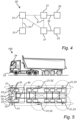
- the upper part of figure 5 is a side view of a vehicle 100 composed of a trailer unit coupled via a fifth wheel and kingpin connection to a tractor unit.
- the lower part of figure 5 is a view from below of the same vehicle 100, wherein the rectangles refer to the approximate contours of the vehicle's 100 lateral surfaces.
- the vehicle 100 is equipped with infrastructure nodes 21, WSGWs 22, ad hoc network access points 23, a cellular antenna 24 and a main processor 41 with the corresponding functionalities as previously described. It is noted that the frontal access points 23 are not roof-mounded, like in figure 1 , but arranged near the road level, in anticipation of intended connecting mobile stations. Antennas with different radiation patterns have been purposefully used for the infrastructure nodes 21 and access points 23, as indicated on the drawing.
- the present disclosure extends to single-unit vehicles 100 as well, whether they include an articulation point or not.
- the vehicles 100 may be passenger vehicles, such as buses, or construction equipment.
- the vehicles 100 may be conventionally operated, semi-autonomous or autonomous.
- Figure 3 is a functional representation of the vehicle network 20 formed by the infrastructure components that were introduced with reference to figures 1 and 2 .
- Figure 3 does not show any parts of the vehicle 100, though its vertical direction generally corresponds to the longitudinal (front-rear) axis of the vehicle 100.
- the infrastructure components including the infrastructure nodes 21, WSGWs 22, ad hoc network access points 23, cellular antennas 24, main processor 40 and wireless communication host 41, reappear in figure 3 .
- the backhaul port 25, where the vehicle network 20 interfaces with the connection towards the global Internet, has been indicated.
- the network's 20 wireless links 31 are drawn in dashed line and wired links 32 in solid line.
- the vehicle network 20 may execute an Ethernet protocol or a Controller Area Network (CAN) protocol. While figure 3 shows a topology where the main processor 40 is connected to the vehicle network 20 via the wireless communication host 41, this disclosure also covers embodiments where the main processor 40 is directly connected, e.g., at the T-shaped junction point below the wireless communication host 41.
- Figure 3 moreover shows potential external communication parties, including a cellular base station 90 (e.g., an LTE eNodeB or 5G-NR gNodeB), with which the cellular antennas 24 communicate over cellular links 33.
- the radio access network (not shown), to which the cellular base station 90 belongs, is supported by a core network, which provides access to the global Internet.
- Traffic from the sensors 50 may include measurement data, and traffic towards the sensors 50 may for example carry transmit requests - especially if the sensors 50 are of a pollable type - or configuration data.
- the mobile stations connecting to those wireless nodes that act as ad hoc network access points 23 are exemplified in figure 3 by an external sensor 60, another vehicle 61 and a handheld device 62.
- This disclosure's usage of the terms “mobile station” and "access point” is occasionally aligned with the terminology in IEEE 802.11 specifications, though compliance with any of these standards is by no means an essential feature of the invention.
- the communication between the access points 23 and the mobile stations 60, 61, 62 may be of the machine-to-machine (M2M) type or vehicle-to-anything (V2x) type, including the V2V, V2N and V2I subtypes.
- M2M machine-to-machine
- V2x vehicle-to-anything
- the external sensor 60 may be a utility meter, i.e., a device for reporting a customer's consumption of electricity, gas, water or other commodities.
- Manual reading of utility meters has been largely abandoned but replaced with the relatively onerous practice of having the utility meters report readings over permanent Internet connections, via cellular subscriber modules or the like.
- a comparable reporting frequency can be achieved by installing a vehicle network 20 of the type described herein in a delivery vehicle, garbage collection vehicle, public transport vehicle or another vehicle that circulates periodically in the residential neighborhoods concerned.
- the wireless access points 23 of the vehicle network 20 will then provide the utility meters with intermittent connectivity on a periodic basis.
- Another advantageous use case is related to mobile stations that are installed or operated in locations without reliable network coverage, including but not limited to subterranean environments (e.g., mines) and tunnels.
- the mobile stations may be machine-type devices or user equipment.
- a vehicle 100 equipped with the vehicle network 20 described herein, which circulates between said location without reliable network coverage and another location where the cellular antennas 24 can successfully establish a connection towards the global Internet, may supply these mobile stations with intermittent connectivity.
- components of the vehicle network 20 may buffer inbound communications from the mobile stations and outbound communications towards the mobile stations.
- Figure 4 shows a vehicle network 20 including infrastructure nodes 21, an ad hoc network access point 23, a backhaul port 25, as well as wireless 31 and wired 32 links among these.
- the network 20 has a mesh topology. More precisely, the top-left and the bottom-right infrastructure nodes 21 are connected by one direct wireless link 31 and one indirect (two-hop) wireless link 31 via the top-right infrastructure node 21.
- the mesh topology may be partial, as shown in figure 4 , or complete in the sense that all wireless nodes 21 have a direct wireless link 31.
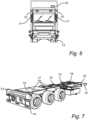
- FIG. 6 a front view of a commercial vehicle, indicates potentially suitable elements in which wireless nodes 21, 22, 23 can be integrated with a view to obtain lines of sights between adjacent ones of the wireless nodes that are sensibly unobstructed and/or sensibly parallel to the surface of the vehicle.
- These elements include a winglet 10 on the trailer, which may be mounted laterally on the driver cab, a side-view mirror 11 or a mirror arm of a side-view mirror 11, a bumper 13 and an air intake 16.
- the air intake 16 may be located at or above roof height of the trailer.
- wireless nodes 21, 22, 23 can be integrated, include: a fin, a fender, a cab shield (i.e., a protective extension of the front edge of a tippable open-box bed), a sun visor above the windscreen and a radiator grille.
- a fin i.e., a fin, a fender, a cab shield (i.e., a protective extension of the front edge of a tippable open-box bed), a sun visor above the windscreen and a radiator grille.
- Figure 7 is a perspective view of a trailer vehicle which shows, similar to figure 6 , elements suitable for fitting network infrastructure components. These include an extender 12, a bumper 13, a front bolster 14, a rear bolster 14, a twistlock beam 15 and a mudguard 17.
- the sidelight 18 mounted on the extender 12 like other lighting components which are nowadays typically powered by semiconductor lighting elements (e.g., light-emitting diode, LED), shall be used with some caution, since LEDs and radio equipment may interfere mutually.
- Passive lighting elements (reflexes) and lighting elements powered by incandescent or other non-interfering technology may successfully absorb by wireless nodes 21, 22, 23, and even retrofitting of complete lighting elements may be an option.
- a wireless node 21, 22, 23 which is physically integrated into an active lighting element may be equipped with a powerline communication interface.
- the wireless node 21, 22, 23 may then use the electric line which powers the lighting element to exchange data with a corresponding powerline communication interface of another component of the vehicle network 20.
- the communication may for example adopt elements of networking standards issued by the HomePlug Powerline Alliance.
- the suitable elements that have been reviewed with reference to figures 6 and 7 may generally be to can be characterized as projecting parts of the vehicle body.
- the projecting parts may belong to the vehicle body as originally manufactured or may have been added subsequently.
- Sensibly unobstructed lines of sights and lines of sights that are sensibly parallel to the surface of a vehicle 100 provide their maximum advantage when they join pairs of infrastructure nodes 21.
- a WSGW 22 and a wireless access point 23 can be mounted without having a direct line of sight to another wireless node.
- the WSGW 22 or wireless access point 23, respectively, may instead communicate with the rest of the vehicle network 20 via a co-located infrastructure node 21 (cf. figure 3 ) or via a wired link 32 (cf. figure 4 ).
Landscapes
- Engineering & Computer Science (AREA)
- Computer Networks & Wireless Communication (AREA)
- Signal Processing (AREA)
- Automation & Control Theory (AREA)
- Mechanical Engineering (AREA)
- Physics & Mathematics (AREA)
- General Physics & Mathematics (AREA)
- Mobile Radio Communication Systems (AREA)
Claims (14)
- Nutzfahrzeug (100) umfassend:
mehrere drahtlose Knoten (21, 22, 23), die an Punkten auf der Oberfläche des Fahrzeugs befestigt und so konfiguriert sind, dass sie zusammenarbeiten, um ein Fahrzeugnetzwerk (20) mit einer Netztopologie zu bilden, wobei:die Sichtlinien zwischen benachbarten drahtlosen Knoten sinnvollerweise nicht behindert werden und/oder sinnvollerweise parallel zur Oberfläche des Fahrzeugs verlaufen;jeder drahtlose Knoten ist so konfiguriert, dass er als mindestens eines der folgenden Elemente fungiert: ein drahtloses Sensor-Gateway zum Sammeln von Daten von Sensoren, ein Ad-hoc-Netzzugangspunkt zur Versorgung mobiler Stationen (60, 61, 62) in der Nähe des Fahrzeugs und ein Infrastrukturknoten, der Datenverbindungen innerhalb des Fahrzeugnetzwerks aufrechterhält;drahtlose Knoten mit unterschiedlichen Rollen im Fahrzeugnetzwerk Antennen mit unterschiedlichen Strahlungsmustern aufweisen; unddas Fahrzeugnetzwerk so konfiguriert ist, dass es Daten weiterleitet, wenn sich die Abdeckung, die den mobilen Stationen in der Nähe des Fahrzeugs angeboten wird, infolge des Fahrzeugmanövrierens dynamisch ändert, wobei die Daten unter Verwendung von Antennen weitergeleitet werden, die den besten Weg bereitstellen; undein Backhaul-Anschluss (25), der konfiguriert ist, um Internet-Konnektivität für das Fahrzeugnetzwerk bereitzustellen. - Nutzfahrzeug nach Anspruch 1, wobei mindestens einer der drahtlosen Knoten ein drahtloses Sensor-Gateway (22) ist, das so konfiguriert ist, dass es Daten von Sensoren (50) im Fahrzeug sammelt.
- Nutzfahrzeug nach Anspruch 1 oder 2, wobei die mehreren drahtlosen Knoten mindestens einen drahtlosen Knoten (21) mit einer Richtantenne und mindestens einen drahtlosen Knoten (22, 23) mit einer Weitwinkelantenne aufweisen.
- Nutzfahrzeug nach einem der vorhergehenden Ansprüche, wobei mindestens einer der drahtlosen Knoten eine Antenne umfasst, die für mindestens 1 GHz, beispielsweise für mindestens 10 GHz, beispielsweise für mindestens 50 GHz angepasst ist.
- Nutzfahrzeug nach einem der vorhergehenden Ansprüche, wobei mindestens einer der drahtlosen Knoten ein intelligentes Antennenmodul umfasst.
- Nutzfahrzeug nach einem der vorhergehenden Ansprüche, wobei mindestens einer der drahtlosen Knoten physisch in ein vorstehendes Teil (10, 11, 12, 13, 14, 15, 16, 17, 18) des Fahrzeugaufbaus integriert ist.
- Nutzfahrzeug nach Anspruch 6, wobei es sich bei dem vorstehenden Teil um einen oder mehrere der folgenden Teile handelt: ein Winglet (10), einen Seitenspiegel (11), einen Spiegelarm, einen Extender (12), eine Finne, einen Kotflügel, ein Fahrerschutzdach, eine Sonnenblende, einen Stoßfänger (13), einen Kühlergrill, einer Front- oder Heckstrebe (14), einen Twistlock-Träger (15), einen Lufteinlass (16), ein Schutzblech (17) .
- Nutzfahrzeug nach einem der vorhergehenden Ansprüche, wobei mindestens einer der drahtlosen Knoten physisch in eine Beleuchtungskomponente (18) des Fahrzeugs integriert ist.
- Nutzfahrzeug nach Anspruch 8, wobei der drahtlose Knoten, der physisch in eine Beleuchtungskomponente integriert ist, eine Schnittstelle für Powerline-Kommunikation umfasst.
- System, das das Nutzfahrzeug nach einem der vorhergehenden Ansprüche umfasst und mindestens eine mobile Station (60, 61, 62), wobei die mindestens eine mobile Station ein Sensor (60), ein anderes Fahrzeug (61) und/oder eine tragbare Vorrichtung (62) ist.
- System nach Anspruch 10, wobei der Sensor ein Verbrauchszähler ist.
- Nutzfahrzeug nach einem der vorhergehenden Ansprüche, das ein autonomes Fahrzeug ist.
- Nutzfahrzeug nach einem der vorhergehenden Ansprüche, das für den Untertage- oder Tunnelbetrieb ausgelegt ist.
- Nutzfahrzeug nach einem der vorhergehenden Ansprüche, das ein Kombinationsfahrzeug ist, das aus zwei oder mehr Fahrzeugeinheiten besteht, von denen jede mindestens einen drahtlosen Knoten umfasst.
Priority Applications (3)
| Application Number | Priority Date | Filing Date | Title |
|---|---|---|---|
| EP21160633.0A EP4054217B1 (de) | 2021-03-04 | 2021-03-04 | Fahrzeug mit fahrzeugnetzwerk |
| US17/677,032 US12143903B2 (en) | 2021-03-04 | 2022-02-22 | Vehicle network |
| CN202210196487.XA CN115009194A (zh) | 2021-03-04 | 2022-03-01 | 车辆网络 |
Applications Claiming Priority (1)
| Application Number | Priority Date | Filing Date | Title |
|---|---|---|---|
| EP21160633.0A EP4054217B1 (de) | 2021-03-04 | 2021-03-04 | Fahrzeug mit fahrzeugnetzwerk |
Publications (3)
| Publication Number | Publication Date |
|---|---|
| EP4054217A1 EP4054217A1 (de) | 2022-09-07 |
| EP4054217C0 EP4054217C0 (de) | 2025-01-22 |
| EP4054217B1 true EP4054217B1 (de) | 2025-01-22 |
Family
ID=74858275
Family Applications (1)
| Application Number | Title | Priority Date | Filing Date |
|---|---|---|---|
| EP21160633.0A Active EP4054217B1 (de) | 2021-03-04 | 2021-03-04 | Fahrzeug mit fahrzeugnetzwerk |
Country Status (3)
| Country | Link |
|---|---|
| US (1) | US12143903B2 (de) |
| EP (1) | EP4054217B1 (de) |
| CN (1) | CN115009194A (de) |
Citations (1)
| Publication number | Priority date | Publication date | Assignee | Title |
|---|---|---|---|---|
| US20200266850A1 (en) * | 2019-02-18 | 2020-08-20 | Ford Global Technologies, Llc | Systems and methods for an external vehicle wireless connection |
Family Cites Families (11)
| Publication number | Priority date | Publication date | Assignee | Title |
|---|---|---|---|---|
| US7421321B2 (en) * | 1995-06-07 | 2008-09-02 | Automotive Technologies International, Inc. | System for obtaining vehicular information |
| US8040226B2 (en) | 2007-04-02 | 2011-10-18 | Datachassi Dc Ab | Vehicle surveillance and communication system |
| CN102029959A (zh) * | 2009-09-29 | 2011-04-27 | 刘义胜 | 使用控制器局域网络总线的车用仪表系统 |
| DE102010064086A1 (de) * | 2010-12-23 | 2012-06-28 | Continental Automotive Gmbh | Fahrzeugantennensystem für V2X Kommunikation |
| US9925921B1 (en) * | 2017-04-17 | 2018-03-27 | Feniex Industries, Inc. | Head tracking control system for controlling an auxiliary vehicle light |
| DE112018003365T5 (de) * | 2017-06-30 | 2020-03-12 | Intel Corporation | V2x-kommunikationen unter verwendung mehrerer funkzugriffstechniken (mehrfach-rat) |
| US20190090174A1 (en) * | 2017-09-18 | 2019-03-21 | Ford Global Technologies, Llc | Vehicle as public wireless hotspot |
| AU2018338210A1 (en) | 2017-09-22 | 2020-04-09 | Consolidated Metco, Inc. | Wheel hub |
| US11052913B2 (en) | 2017-10-23 | 2021-07-06 | Uatc, Llc | Cargo trailer sensor assembly |
| CN108895914A (zh) * | 2018-08-16 | 2018-11-27 | 中众航(天津)实业有限公司 | 无人驾驶遥感遥控靶车 |
| US11019157B2 (en) * | 2019-03-06 | 2021-05-25 | At&T Intellectual Property I, L.P. | Connectionless service and other services for devices using microservices in 5G or other next generation communication systems |
-
2021
- 2021-03-04 EP EP21160633.0A patent/EP4054217B1/de active Active
-
2022
- 2022-02-22 US US17/677,032 patent/US12143903B2/en active Active
- 2022-03-01 CN CN202210196487.XA patent/CN115009194A/zh active Pending
Patent Citations (1)
| Publication number | Priority date | Publication date | Assignee | Title |
|---|---|---|---|---|
| US20200266850A1 (en) * | 2019-02-18 | 2020-08-20 | Ford Global Technologies, Llc | Systems and methods for an external vehicle wireless connection |
Also Published As
| Publication number | Publication date |
|---|---|
| EP4054217C0 (de) | 2025-01-22 |
| EP4054217A1 (de) | 2022-09-07 |
| CN115009194A (zh) | 2022-09-06 |
| US20220286825A1 (en) | 2022-09-08 |
| US12143903B2 (en) | 2024-11-12 |
Similar Documents
| Publication | Publication Date | Title |
|---|---|---|
| Choi et al. | Millimeter-wave vehicular communication to support massive automotive sensing | |
| Va et al. | Millimeter wave vehicular communications: A survey | |
| KR102568209B1 (ko) | 차량에 배치되는 광대역 안테나 | |
| KR102552305B1 (ko) | 차량에 배치되는 광대역 안테나 | |
| KR102725688B1 (ko) | 차량에 배치되는 안테나 모듈 | |
| US12325381B2 (en) | Detection device | |
| Eldeeb et al. | Visible light communication for connected vehicles: How to achieve the omnidirectional coverage? | |
| KR102677753B1 (ko) | 차량에 배치되는 광대역 안테나 | |
| KR102707822B1 (ko) | 차량에 배치되는 안테나 모듈 | |
| KR102947357B1 (ko) | 차량에 배치되는 광대역 안테나 | |
| KR20200101869A (ko) | 무선 통신을 수행하는 방법, 모바일 스테이션, 차량 및 기지국 | |
| EP4054217B1 (de) | Fahrzeug mit fahrzeugnetzwerk | |
| US12513756B2 (en) | Communication apparatus and communication method | |
| Yin et al. | Design of antenna configuration for interference control in mmwave V2V communication systems | |
| KR102946365B1 (ko) | 차량에 배치되는 광대역 안테나 | |
| KR102938453B1 (ko) | 차량에 배치되는 광대역 안테나 | |
| KR20240070595A (ko) | 차량에 배치되는 광대역 안테나 | |
| Yacoub et al. | Low profile PIFA antenna for vehicular 5G and DSRC communication systems | |
| KR102656900B1 (ko) | C-v2x 통신 및 wave 통신을 지원하는 차량의 신호 간섭 방지 방법 및 상기 방법을 이용하는 차량 탑재 장치 | |
| JP2004072268A (ja) | 車々間通信方法 | |
| KR20240042538A (ko) | 차량에 배치되는 광대역 안테나 | |
| KR20240043155A (ko) | 차량에 배치되는 광대역 안테나 | |
| Oh et al. | Exploiting vertical diversity in vehicular channel environments | |
| Muramatsu | Measurement of radio propagation characteristics for inter-vehicle communication in urban areas | |
| Choi et al. | Combining millimeter-wave radar and communication paradigms for automotive applications: a signal processing approach. |
Legal Events
| Date | Code | Title | Description |
|---|---|---|---|
| PUAI | Public reference made under article 153(3) epc to a published international application that has entered the european phase |
Free format text: ORIGINAL CODE: 0009012 |
|
| STAA | Information on the status of an ep patent application or granted ep patent |
Free format text: STATUS: REQUEST FOR EXAMINATION WAS MADE |
|
| 17P | Request for examination filed |
Effective date: 20211109 |
|
| AK | Designated contracting states |
Kind code of ref document: A1 Designated state(s): AL AT BE BG CH CY CZ DE DK EE ES FI FR GB GR HR HU IE IS IT LI LT LU LV MC MK MT NL NO PL PT RO RS SE SI SK SM TR |
|
| STAA | Information on the status of an ep patent application or granted ep patent |
Free format text: STATUS: EXAMINATION IS IN PROGRESS |
|
| 17Q | First examination report despatched |
Effective date: 20221216 |
|
| RIC1 | Information provided on ipc code assigned before grant |
Ipc: H04W 84/00 20090101ALI20240705BHEP Ipc: H04W 4/48 20180101ALI20240705BHEP Ipc: H04W 4/40 20180101AFI20240705BHEP |
|
| GRAP | Despatch of communication of intention to grant a patent |
Free format text: ORIGINAL CODE: EPIDOSNIGR1 |
|
| STAA | Information on the status of an ep patent application or granted ep patent |
Free format text: STATUS: GRANT OF PATENT IS INTENDED |
|
| INTG | Intention to grant announced |
Effective date: 20240903 |
|
| GRAS | Grant fee paid |
Free format text: ORIGINAL CODE: EPIDOSNIGR3 |
|
| GRAA | (expected) grant |
Free format text: ORIGINAL CODE: 0009210 |
|
| STAA | Information on the status of an ep patent application or granted ep patent |
Free format text: STATUS: THE PATENT HAS BEEN GRANTED |
|
| AK | Designated contracting states |
Kind code of ref document: B1 Designated state(s): AL AT BE BG CH CY CZ DE DK EE ES FI FR GB GR HR HU IE IS IT LI LT LU LV MC MK MT NL NO PL PT RO RS SE SI SK SM TR |
|
| REG | Reference to a national code |
Ref country code: GB Ref legal event code: FG4D |
|
| REG | Reference to a national code |
Ref country code: CH Ref legal event code: EP |
|
| REG | Reference to a national code |
Ref country code: IE Ref legal event code: FG4D |
|
| REG | Reference to a national code |
Ref country code: DE Ref legal event code: R096 Ref document number: 602021025033 Country of ref document: DE |
|
| U01 | Request for unitary effect filed |
Effective date: 20250207 |
|
| U07 | Unitary effect registered |
Designated state(s): AT BE BG DE DK EE FI FR IT LT LU LV MT NL PT RO SE SI Effective date: 20250213 |
|
| U20 | Renewal fee for the european patent with unitary effect paid |
Year of fee payment: 5 Effective date: 20250218 |
|
| PG25 | Lapsed in a contracting state [announced via postgrant information from national office to epo] |
Ref country code: RS Free format text: LAPSE BECAUSE OF FAILURE TO SUBMIT A TRANSLATION OF THE DESCRIPTION OR TO PAY THE FEE WITHIN THE PRESCRIBED TIME-LIMIT Effective date: 20250422 |
|
| PG25 | Lapsed in a contracting state [announced via postgrant information from national office to epo] |
Ref country code: PL Free format text: LAPSE BECAUSE OF FAILURE TO SUBMIT A TRANSLATION OF THE DESCRIPTION OR TO PAY THE FEE WITHIN THE PRESCRIBED TIME-LIMIT Effective date: 20250122 |
|
| PG25 | Lapsed in a contracting state [announced via postgrant information from national office to epo] |
Ref country code: ES Free format text: LAPSE BECAUSE OF FAILURE TO SUBMIT A TRANSLATION OF THE DESCRIPTION OR TO PAY THE FEE WITHIN THE PRESCRIBED TIME-LIMIT Effective date: 20250122 |
|
| PG25 | Lapsed in a contracting state [announced via postgrant information from national office to epo] |
Ref country code: NO Free format text: LAPSE BECAUSE OF FAILURE TO SUBMIT A TRANSLATION OF THE DESCRIPTION OR TO PAY THE FEE WITHIN THE PRESCRIBED TIME-LIMIT Effective date: 20250422 Ref country code: IS Free format text: LAPSE BECAUSE OF FAILURE TO SUBMIT A TRANSLATION OF THE DESCRIPTION OR TO PAY THE FEE WITHIN THE PRESCRIBED TIME-LIMIT Effective date: 20250522 |
|
| PG25 | Lapsed in a contracting state [announced via postgrant information from national office to epo] |
Ref country code: HR Free format text: LAPSE BECAUSE OF FAILURE TO SUBMIT A TRANSLATION OF THE DESCRIPTION OR TO PAY THE FEE WITHIN THE PRESCRIBED TIME-LIMIT Effective date: 20250122 |
|
| PG25 | Lapsed in a contracting state [announced via postgrant information from national office to epo] |
Ref country code: GR Free format text: LAPSE BECAUSE OF FAILURE TO SUBMIT A TRANSLATION OF THE DESCRIPTION OR TO PAY THE FEE WITHIN THE PRESCRIBED TIME-LIMIT Effective date: 20250423 |
|
| PG25 | Lapsed in a contracting state [announced via postgrant information from national office to epo] |
Ref country code: SM Free format text: LAPSE BECAUSE OF FAILURE TO SUBMIT A TRANSLATION OF THE DESCRIPTION OR TO PAY THE FEE WITHIN THE PRESCRIBED TIME-LIMIT Effective date: 20250122 |
|
| PG25 | Lapsed in a contracting state [announced via postgrant information from national office to epo] |
Ref country code: MC Free format text: LAPSE BECAUSE OF FAILURE TO SUBMIT A TRANSLATION OF THE DESCRIPTION OR TO PAY THE FEE WITHIN THE PRESCRIBED TIME-LIMIT Effective date: 20250122 |
|
| PG25 | Lapsed in a contracting state [announced via postgrant information from national office to epo] |
Ref country code: CZ Free format text: LAPSE BECAUSE OF FAILURE TO SUBMIT A TRANSLATION OF THE DESCRIPTION OR TO PAY THE FEE WITHIN THE PRESCRIBED TIME-LIMIT Effective date: 20250122 |
|
| REG | Reference to a national code |
Ref country code: CH Ref legal event code: H13 Free format text: ST27 STATUS EVENT CODE: U-0-0-H10-H13 (AS PROVIDED BY THE NATIONAL OFFICE) Effective date: 20251024 |
|
| PG25 | Lapsed in a contracting state [announced via postgrant information from national office to epo] |
Ref country code: SK Free format text: LAPSE BECAUSE OF FAILURE TO SUBMIT A TRANSLATION OF THE DESCRIPTION OR TO PAY THE FEE WITHIN THE PRESCRIBED TIME-LIMIT Effective date: 20250122 |
|
| PLBE | No opposition filed within time limit |
Free format text: ORIGINAL CODE: 0009261 |
|
| STAA | Information on the status of an ep patent application or granted ep patent |
Free format text: STATUS: NO OPPOSITION FILED WITHIN TIME LIMIT |
|
| GBPC | Gb: european patent ceased through non-payment of renewal fee |
Effective date: 20250422 |
|
| 26N | No opposition filed |
Effective date: 20251023 |
|
| PG25 | Lapsed in a contracting state [announced via postgrant information from national office to epo] |
Ref country code: GB Free format text: LAPSE BECAUSE OF NON-PAYMENT OF DUE FEES Effective date: 20250422 |
|
| PG25 | Lapsed in a contracting state [announced via postgrant information from national office to epo] |
Ref country code: CH Free format text: LAPSE BECAUSE OF NON-PAYMENT OF DUE FEES Effective date: 20250331 |
|
| PG25 | Lapsed in a contracting state [announced via postgrant information from national office to epo] |
Ref country code: IE Free format text: LAPSE BECAUSE OF NON-PAYMENT OF DUE FEES Effective date: 20250304 |