EP4054280A1 - Verfahren und vorrichtung zur verarbeitung von funkverbindungsfehlern - Google Patents
Verfahren und vorrichtung zur verarbeitung von funkverbindungsfehlern Download PDFInfo
- Publication number
- EP4054280A1 EP4054280A1 EP20882356.7A EP20882356A EP4054280A1 EP 4054280 A1 EP4054280 A1 EP 4054280A1 EP 20882356 A EP20882356 A EP 20882356A EP 4054280 A1 EP4054280 A1 EP 4054280A1
- Authority
- EP
- European Patent Office
- Prior art keywords
- terminal
- radio link
- information
- link failure
- base station
- Prior art date
- Legal status (The legal status is an assumption and is not a legal conclusion. Google has not performed a legal analysis and makes no representation as to the accuracy of the status listed.)
- Pending
Links
Images


Classifications
-
- H—ELECTRICITY
- H04—ELECTRIC COMMUNICATION TECHNIQUE
- H04W—WIRELESS COMMUNICATION NETWORKS
- H04W76/00—Connection management
- H04W76/10—Connection setup
- H04W76/18—Management of setup rejection or failure
-
- H—ELECTRICITY
- H04—ELECTRIC COMMUNICATION TECHNIQUE
- H04W—WIRELESS COMMUNICATION NETWORKS
- H04W76/00—Connection management
- H04W76/10—Connection setup
- H04W76/19—Connection re-establishment
-
- H—ELECTRICITY
- H04—ELECTRIC COMMUNICATION TECHNIQUE
- H04W—WIRELESS COMMUNICATION NETWORKS
- H04W24/00—Supervisory, monitoring or testing arrangements
- H04W24/10—Scheduling measurement reports ; Arrangements for measurement reports
-
- H—ELECTRICITY
- H04—ELECTRIC COMMUNICATION TECHNIQUE
- H04W—WIRELESS COMMUNICATION NETWORKS
- H04W72/00—Local resource management
-
- H—ELECTRICITY
- H04—ELECTRIC COMMUNICATION TECHNIQUE
- H04W—WIRELESS COMMUNICATION NETWORKS
- H04W74/00—Wireless channel access
-
- H—ELECTRICITY
- H04—ELECTRIC COMMUNICATION TECHNIQUE
- H04W—WIRELESS COMMUNICATION NETWORKS
- H04W76/00—Connection management
- H04W76/30—Connection release
- H04W76/34—Selective release of ongoing connections
- H04W76/36—Selective release of ongoing connections for reassigning the resources associated with the released connections
-
- H—ELECTRICITY
- H04—ELECTRIC COMMUNICATION TECHNIQUE
- H04W—WIRELESS COMMUNICATION NETWORKS
- H04W76/00—Connection management
- H04W76/10—Connection setup
- H04W76/14—Direct-mode setup
-
- H—ELECTRICITY
- H04—ELECTRIC COMMUNICATION TECHNIQUE
- H04W—WIRELESS COMMUNICATION NETWORKS
- H04W76/00—Connection management
- H04W76/30—Connection release
Definitions
- This disclosure relates to the field of communications technologies, and in particular, to a method and an apparatus for handling radio link failure.
- LTE Long Term Evolution
- sidelink is used for direct data transmission between user equipments (User Equipment, UE) without a network device.
- Uplink is for uplink transmission
- downlink is for downlink transmission.
- Embodiments of this disclosure provide a method and an apparatus for handling radio link failure, so as to release and reclaim resources for a failed radio link in a timely manner.
- an embodiment of this disclosure provides a method for handling radio link failure, applied to a first terminal and including:
- an embodiment of this disclosure provides a method for handling radio link failure, applied to a first base station and including:
- an embodiment of this disclosure further provides an apparatus for handling radio link failure, applied to a first terminal and including:
- an apparatus for handling radio link failure applied to a first base station and including:
- an embodiment of this disclosure further provides a communications device, where the communications device includes a processor, a memory, and a computer program stored in the memory and running on the processor, and when the processor executes the computer program, the steps of the foregoing method for handling radio link failure are implemented.
- an embodiment of this disclosure further provides a computer-readable storage medium, where the computer-readable storage medium stores a computer program, and when the computer program is executed by a processor, the steps of the foregoing method for handling radio link failure are implemented.
- the first terminal after detecting the radio link failure between the first terminal and the second terminal, the first terminal reports the indication message of the radio link failure to a first serving base station of the first terminal.
- the first serving base station of the first terminal learns the radio link failure in a timely manner and performs handling, so that the resource for the failed radio link can be released and reclaimed in a timely manner, thereby avoiding waste of resources, better controlling radio link data transmission, and providing better user experience.
- LTE Long Term Evolution
- LTE-Advanced LTE-Advanced
- LTE-A Long Term Evolution-Advanced
- CDMA code division multiple access
- Time Division Multiple Access Time Division Multiple Access
- FDMA frequency division multiple access
- OFDMA Orthogonal Frequency Division Multiple Access
- SC-FDMA single-carrier Frequency-Division Multiple Access
- SC-FDMA single-carrier Frequency-Division Multiple Access
- the CDMA system may implement radio technologies such as CDMA2000 and universal terrestrial radio access (Universal Terrestrial Radio Access, UTRA).
- UTRA includes wideband CDMA (Wideband Code Division Multiple Access, WCDMA) and other CDMA variants.
- the TDMA system can implement radio technologies such as global system for mobile communications (Global System for Mobile Communication, GSM).
- GSM Global System for Mobile Communication
- the OFDMA system can implement radio technologies such as ultra mobile broadband (Ultra Mobile Broadband, UMB), evolved UTRA (Evolution-UTRA, E-UTRA), IEEE 802.11 (Wi-Fi), IEEE 802.16 (WiMAX), IEEE 802.20, and Flash-OFDM.
- UTRA and E-UTRA are part of the universal mobile telecommunications system (Universal Mobile Telecommunications System, UMTS).
- LTE and more advanced LTEs are new releases of UMTS that use E-UTRA.
- UTRA, E-UTRA, UMTS, LTE, LTE-A, and GSM are described in documents from an organization named "3rd Generation Partnership Project” (3rd Generation Partnership Project, 3GPP).
- CDMA2000 and UMB are described in documents from an organization named "3rd Generation Partnership Project 2" (3GPP2).
- the technologies described herein are applicable not only to the above-mentioned systems and radio technologies, but also to other systems and radio technologies.
- an NR system is described for an illustration purpose, and NR terms are used in most of the following descriptions, although these technologies may also be applied to other applications than an NR system application.
- LTE Long Term Evolution
- sidelink is used for direct data transmission between user equipments (User Equipment, UE) without through a network device.
- Uplink is for uplink transmission
- downlink is for downlink transmission.
- LTE sidelink is designed to be applicable to specific public safety affairs (for example, emergency communication on a fire site or a disaster site such as an earthquake), vehicle to everything (vehicle to everything, V2X) communication, or the like.
- the vehicle to everything communication includes various services, for example, basic security communication, advanced (autonomous) driving, platooning, and sensor extension.
- LTE sidelink supports only broadcast communication, and therefore is mainly used for basic security communication.
- Other advanced V2X services with strict quality of service (Quality of Service, QoS) requirements in terms of delay and reliability are supported by new radio (New Radio, NR) sidelink.
- QoS Quality of Service
- the 5G NR system may be used in operating bands above 6 GHz that are not supported by LTE, and supports a larger operating bandwidth.
- the existing NR system only supports an interface between a base station and a terminal, and does not support a sidelink interface for direct communication between terminals.
- the sidelink interface may also be called PC5 interface.
- sidelink transmission mainly includes: broadcast (broadcast), groupcast (groupcast), and unicast (unicast).
- Unicast is a one-to-one (one to one) transmission.
- Groupcast is a one-to-many (one to many) transmission.
- Broadcast is also a one-to-many transmission, but for broadcast, there is no concept that UEs belong to a same group.
- HARQ physical layer hybrid automatic repeat request
- Resource allocation modes of sidelink UE are divided into two categories:
- radio link failure may be triggered due to the following causes: a physical layer reports that a link is poor and is unable to be recovered within a specified period of time; media access control (Media Access Control, MAC) indicates a random access problem; and a maximum number of radio link control (Radio Link Control, RLC) acknowledgment mode (AM) retransmissions has been reached.
- RLF Radio Link Failure
- the method for handling radio link failure of the Uu interface is not applicable to the sidelink interface, and there is no further solution to handling the a radio link failure of the sidelink interface.
- the embodiments of this disclosure provide a method and an apparatus for handling radio link failure, so as to release and reclaim resources for a failed radio link in a timely manner.
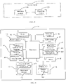
- An embodiment of this disclosure provides a method for handling radio link failure applied to a first terminal and, as shown in FIG. 2 , including the following steps.
- Step 101 Detect a radio link failure between the first terminal and a second terminal.
- Step 102 Report an indication message of the radio link failure to a serving base station of the first terminal, where the indication message includes at least one of the following information:
- the first terminal after detecting the radio link failure between the first terminal and the second terminal, the first terminal reports the indication message of the radio link failure to a first serving base station of the first terminal.
- the first serving base station of the first terminal learns the radio link failure in a timely manner and performs handling, so that the resource for the failed radio link can be released and reclaimed in a timely manner, thereby avoiding waste of resources, better controlling radio link data transmission, and providing better user experience.
- the radio link may be a PC5 link.
- the radio link is not limited to a PC5 link, and may also be other types of radio links.
- the method before the detecting a radio link failure between the first terminal and a second terminal, the method further includes any one of the following:
- the first terminal and the second terminal can exchange the information of their respective serving base stations before the radio link fails, so that the first terminal and the second terminal can learn the information of the serving base station of the peer terminal.
- the first terminal after the first terminal changes its serving base station, the first terminal also needs to send a third notification message to the second terminal, where the third notification message includes information of the serving base station of the first terminal, so that the second terminal learns the latest serving base station of the first terminal in a timely manner.
- the first notification message is not limited to the information of the serving base station of the second terminal, and may also include an identity of the second terminal and/or information of the radio link.
- the second notification message is not limited to the information of the serving base station of the first terminal, and may also include an identity of the first terminal and/or the information of the radio link.
- the information of the serving base station of the first terminal includes at least one of the following:
- the cell identifier has 28 bits
- the base station identifier has 20 bits
- the base station identifier is the first 20 bits of the cell identifier.
- the cell identifier is not limited to 28 bits
- the base station identifier is not limited to 20 bits, and other number of bits may be used.
- the terminal can be found based on a UE identifier. After the terminal is found, it is also necessary to determine, based on the information of the radio link, which radio link of the UE encounters a problem.
- the method further includes: reporting information of the second terminal to the serving base station of the first terminal, where the information of the second terminal includes at least one of the following:
- the serving base station of the first terminal may know the information of the radio link, or may not obtain accurate information of the radio link. In this case, the first terminal needs to report the information of the radio link.
- the information of the second terminal includes first information about whether the second terminal is a transmit end; or the information of the second terminal is reported by the first terminal to the serving base station of the first terminal in a case that the second terminal is a transmit end.
- An embodiment of this disclosure further provides a method for handling radio link failure, applied to a first base station and, as shown in FIG. 3 , including:
- Step 201 Receive an indication message of a radio link failure reported by a first terminal, where the indication message includes at least one of the following information: an identifier of radio link, an indication of radio link failure, and a cause of the radio link failure.
- Step 202 Release a resource corresponding to the radio link.
- the first terminal after detecting the radio link failure between the first terminal and a second terminal, the first terminal reports the indication message of the radio link failure to a first serving base station of the first terminal.
- the first serving base station of the first terminal learns the radio link failure in a timely manner and performs handling, so that the resource for the failed radio link can be released and reclaimed in a timely manner, thereby avoiding waste of resources, better controlling radio link data transmission, and providing better user experience.
- One or more radio links may be present between the first terminal and the second terminal.
- the first terminal may report an indication message of failure of one or more of the radio links to the second terminal.
- the resource corresponding to the radio link includes at least one of the following:
- the method further includes: receiving information of a second terminal reported by the first terminal, where the radio link is a radio link between the first terminal and the second terminal, and the information of the second terminal includes at least one of the following:
- the method further includes: sending a first indication message to a second base station to indicate radio link failure between the second terminal and the first terminal, where the first indication message is used for the second base station to release the resource corresponding to the radio link, and the second base station is a serving base station of the second terminal, so that the second base station can reclaim and release the resource of the radio link.
- the sending a first indication message to a second base station includes: sending the first indication message to the second base station through an Xn and/or X2 interface.
- the first indication message includes at least one of the following:
- the information of the second terminal includes first information about whether the second terminal is a transmit end; or the information of the second terminal is reported by the first terminal in a case that the second terminal is a transmit end.
- a terminal reports a radio link failure message to a base station.
- radio link failure may be triggered by at least one of the following causes:
- the first trigger manner is typically triggered by a receive end. Because there is no periodic or continuous transmission of reference signals on the sidelink interface, quality measurement of the physical layer is based on the reference signal transmitted with the data, and only the recipient of the data can perform link quality measurement. In the case of unidirectional service transmission, only the UE at one end may perform measurement. In the case of bidirectional service transmission, the UEs at both ends may perform measurement.
- the second trigger manner is an action of the transmit end, and can only be triggered by the transmit end. In a case that services are sent at both ends, both ends can trigger the RLF as a transmit end.
- the UE detecting the RLF can report such condition to the base station, where the reported information may include at least one of the following:
- the base station After receiving the RLF report, the base station releases the resource corresponding to the radio link, such as a dedicated sidelink pool resource, a periodically configured sidelink resource, or a Uu interface resource for assisting the sidelink.
- the radio link such as a dedicated sidelink pool resource, a periodically configured sidelink resource, or a Uu interface resource for assisting the sidelink.
- UEs at both ends of a radio link exchange respective information.
- UEs at both ends of sidelink unicast may exchange information of serving base stations of the UEs, and may also exchange identity information of the UEs and/or information of the radio link.
- the UEs when a sidelink is being established or configured, exchange information of their own serving base stations with each other, or may also exchange the identity information of the UEs, and/or the information of the radio link.
- the information of the serving base station may be a cell identifier cell ID of a Pcell (primary cell) for UE in a connected state, or may be a cell identifier of a camping cell for UE in an idle (Idle)/inactive (inactive) state.
- the identity information of the UE and the information of the radio link may be a V2X link ID, a destination L2 ID, a cell-radio network temporary identifier (Cell-Radio Network Temporary Identifier, CRNTI) of UE in a connected state, an Inactive Resume ID, and the like, as long as another base station can find the peer-end UE on the link corresponding to the UE.
- CRNTI Cell-Radio Network Temporary Identifier
- the information exchange may be performed in combination with or in parallel with capability reporting or link configuration.
- the serving base station of the UE is changing. For example, when handover and cell reselection occur, the UE needs to update information of its serving base station for the peer-end UE, that is, when its serving base station changes, the UE is triggered to report the change of its serving base station to the peer-end UE by using PC5 radio resource control (radio resource control, RRC) signaling that carries information of the latest serving base station of the UE, and optionally, may also carry identity information of the UE and/or information of the radio link to identify the UE.
- PC5 radio resource control radio resource control
- the UE at each end of the sidelink After the UE at each end of the sidelink obtains information of the serving base station of the peer-end UE or updated information of the serving base station of the peer-end UE through RRC signaling exchange, the UE reports the information to its serving base station to store the information as context information of the UE.
- the information is first stored in the UE, and when reporting is needed, for example, when RLF is triggered, the information is reported to the serving base station with the RLF, so that the serving base station releases a resource of the peer-end UE. This eliminates the Uu interface reporting and updating procedures, and the information only needs to be reported together with the RLF.
- the first base station notifies the second base station of radio link failure.
- Data volumes of UEs at two ends of the sidelink unicast may be unequal.
- the UE having a larger amount of data will have more measurement opportunities, and the UE having a smaller amount of data will have fewer measurement opportunities. Therefore, when RLF occurs, it is very likely that only the UE at one end has detected the RLF, while the UE at the other end has not detected the RLF yet. In this case, the UE that has detected the RLF can notify the other UE to release resources, which can improve the utilization of the resources.
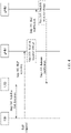
- Step 301 UE1 (that is, the first base station) performs sidelink link detection.
- Step 302 When RLF is detected, UE1 reports the RLF to its serving base station gNB1 (that is, the first base station).
- Step 303 gNB1 releases a sidelink resource.
- Step 304 gNB1 notifies gNB2 (that is, the second base station) of the RLF.
- the serving base station gNB1 can send sidelink RLF indication information to gNB2 through an Xn/X2 interface.
- the indication information needs to carry a sidelink RLF indication, a UE2 indication, a link ID or destination ID indication of the sidelink link, or the like, so that gNB2 can find the corresponding UE2 and/or the information of the radio link and perform release processing correctly.
- Step 305 gNB2 releases a sidelink resource.
- the base station gNB2 After receiving the sidelink RLF information from gNB1, the base station gNB2 finds the corresponding UE2 and/or the radio link based on the carried information, and releases a sidelink link resource for the radio link with the radio link failure.
- Step 306 gNB2 sends a release notification to UE2 (that is, the second terminal).
- the base station gNB2 may also release UE2, indicating that RLF has occurred, and the sidelink communication may end.
- UE1 in a case that UE1 as a sidelink receive end determines that a condition for triggering RLF is met by measuring a reference signal in the received data, UE1 reports the RLF to its serving base station gNB1. Because there may be a plurality of links between UE1 and UE2, it is necessary to indicate which sidelink link fails, and also indicate information of the peer-end UE, including information of the serving base station gNB2 and identity information of UE2, radio link information, and the like.
- gNB 1 may release a resource of the sidelink at its end, and send an Xn and/or X2 message to the serving base station gNB2 of the peer-end UE2, notifying gNB2 of the RLF of the sidelink.
- gNB2 may release a corresponding resource based on the information of UE2 and information of the radio link that are carried in the message, and send a sidelink link release message to UE2 through the Uu interface to end the sidelink communication and reclaim the resource.
- a link and resource of the peer-end UE can be directly released without interface signaling exchange.
- the UE can also report some additional information, for example, whether the peer-end UE is a transmit end. This is because only a transmit-end UE needs to release a resource. If the peer-end UE is not a transmit-end UE, it is not necessary to notify, through an Xn and/or X2 message, the peer-end UE to release the radio link.
- the UE reports information of the serving base station of the peer-end UE, to implicitly indicate whether it is necessary to notify, through an Xn and/or X2 message, the peer-end UE to release the radio link.
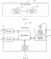
- An embodiment of this disclosure further provides an apparatus for handling radio link failure, applied to a first terminal.
- the first terminal 300 includes:
- the first terminal after detecting the radio link failure between the first terminal and the second terminal, the first terminal reports the indication message of the radio link failure to a first serving base station of the first terminal.
- the first serving base station of the first terminal learns the radio link failure in a timely manner and performs handling, so that the resource for the failed radio link can be released and reclaimed in a timely manner, thereby avoiding waste of resources, better controlling radio link data transmission, and providing better user experience.
- the radio link may be a PC5 link.
- the radio link is not limited to a PC5 link, and may also be other types of radio links.
- the apparatus further includes: a transceiver module, configured to, before the radio link failure between the first terminal and the second terminal is detected, receive a first notification message of the second terminal, where the first notification message includes information of a serving base station of the second terminal; and/or send a second notification message to the second terminal, where the second notification message includes information of the serving base station of the first terminal.
- a transceiver module configured to, before the radio link failure between the first terminal and the second terminal is detected, receive a first notification message of the second terminal, where the first notification message includes information of a serving base station of the second terminal; and/or send a second notification message to the second terminal, where the second notification message includes information of the serving base station of the first terminal.
- the first terminal and the second terminal can exchange the information of their respective serving base stations before the radio link fails, so that the first terminal and the second terminal can learn the information of the serving base station of the peer terminal.
- the first terminal after the first terminal changes its serving base station, the first terminal also needs to send a third notification message to the second terminal, where the third notification message includes information of the serving base station of the first terminal, so that the second terminal learns the latest serving base station of the first terminal in a timely manner.
- the first notification message is not limited to the information of the serving base station of the second terminal, and may also include an identity of the second terminal and/or information of the radio link.
- the second notification message is not limited to the information of the serving base station of the first terminal, and may also include an identity of the first terminal and/or the information of the radio link.
- the information of the serving base station of the first terminal includes at least one of the following:
- the cell identifier has 28 bits
- the base station identifier has 20 bits
- the base station identifier is the first 20 bits of the cell identifier.
- the cell identifier is not limited to 28 bits
- the base station identifier is not limited to 20 bits, and other number of bits may be used.
- the terminal can be found based on a UE identifier. After the terminal is found, it is also necessary to determine, based on the information of the radio link, which radio link of the UE encounters a problem.
- the transceiver module is further configured to report information of the second terminal to the serving base station of the first terminal, where the information of the second terminal includes at least one of the following:
- the serving base station of the first terminal may know the information of the radio link, or may not obtain accurate information of the radio link. In this case, the first terminal needs to report the information of the radio link.
- the information of the second terminal includes first information about whether the second terminal is a transmit end; or the information of the second terminal is reported by the first terminal to the serving base station of the first terminal in a case that the second terminal is a transmit end.
- An embodiment of this disclosure further provides an apparatus for handling radio link failure, applied to a first base station.
- the first base station 500 includes:
- the first terminal after detecting the radio link failure between the first terminal and a second terminal, the first terminal reports the indication message of the radio link failure to a first serving base station of the first terminal.
- the first serving base station of the first terminal learns the radio link failure in a timely manner and performs handling, so that the resource for the failed radio link can be released and reclaimed in a timely manner, thereby avoiding waste of resources, better controlling radio link data transmission, and providing better user experience.
- One or more radio links may be present between the first terminal and the second terminal.
- the resource corresponding to the radio link includes at least one of the following:
- the receiving module is further configured to receive information of a second terminal reported by the first terminal, where the radio link is a radio link between the first terminal and the second terminal, and the information of the second terminal includes at least one of the following:
- the apparatus further includes: a sending module, configured to, after the indication message of the radio link failure reported by the first terminal is received, send a first indication message to a second base station to indicate the radio link failure between the second terminal and the first terminal, where the first indication message is used for the second base station to release a resource corresponding to the radio link, and the second base station is the serving base station of the second terminal.
- a sending module configured to, after the indication message of the radio link failure reported by the first terminal is received, send a first indication message to a second base station to indicate the radio link failure between the second terminal and the first terminal, where the first indication message is used for the second base station to release a resource corresponding to the radio link, and the second base station is the serving base station of the second terminal.
- the sending module is configured to send the first indication message to the second base station through an Xn and/or X2 interface.
- the first indication message includes at least one of the following:
- the information of the second terminal includes first information about whether the second terminal is a transmit end; or the information of the second terminal is reported by the first terminal in a case that the second terminal is a transmit end.
- An embodiment of this disclosure further provides a communications device, where the communications device includes a processor, a memory, and a computer program stored in the memory and running on the processor; and when the processor executes the computer program, the steps of the method for handling radio link failure are implemented.
- the communications device may be a terminal or a base station.
- FIG. 6 is a schematic diagram of a hardware structure of a terminal for implementing each embodiment of this disclosure.
- the terminal 40 includes but is not limited to components such as a radio frequency unit 41, a network module 42, an audio output unit 43, an input unit 44, a sensor 45, a display unit 46, a user input unit 47, an interface unit 48, a memory 49, a processor 410, and a power supply 411.
- a person skilled in the art may understand that the structure of the terminal shown in FIG. 6 does not constitute any limitation on the terminal.
- the terminal may include more or fewer components than those shown in the figure, or some components are combined, or component arrangements are different.
- the terminal includes but is not limited to a mobile phone, a tablet computer, a notebook computer, a palmtop computer, an in-vehicle terminal, a wearable device, a pedometer, and the like.
- the processor 410 is configured to detect a radio link failure between the terminal and the second terminal and report an indication message of the radio link failure to a serving base station of the terminal, where the indication message includes at least one of the following information:
- the radio frequency unit 41 may be configured to transmit or receive a signal in an information transmitting/receiving or call process. Specifically, the radio frequency unit 41 receives downlink data from a base station, transmits the downlink data to the processor 410 for processing, and transmits uplink data to the base station.
- the radio frequency unit 41 includes but is not limited to an antenna, at least one amplifier, a transceiver, a coupler, a low noise amplifier, a duplexer, and the like.
- the radio frequency unit 41 may further communicate with a network and other devices via a wireless communications system.
- the terminal provides a user with wireless broadband Internet access by using the network module 42, for example, helping the user to transmit and receive e-mails, browse web pages, and access streaming media.
- the audio output unit 43 may convert audio data received by the radio frequency unit 41 or the network module 42 or stored in the memory 49 into an audio signal and output the audio signal as a sound.
- the audio output unit 43 may further provide audio output (for example, a call signal received tone or a message received tone) that is related to a specific function performed by the terminal 40.
- the audio output unit 43 includes a speaker, a buzzer, a receiver, and the like.
- the input unit 44 is configured to receive an audio signal or a video signal.
- the input unit 44 may include a graphics processing unit (Graphics Processing Unit, GPU) 441 and a microphone 442.
- the graphics processing unit 441 processes image data of a static picture or a video obtained by an image capture apparatus (for example, a camera) in an image capture mode or a video capture mode.
- a processed image frame may be displayed on the display unit 46.
- the image frame processed by the graphics processing unit 441 may be stored in the memory 49 (or another storage medium) or transmitted by using the radio frequency unit 41 or the network module 42.
- the microphone 442 is capable of receiving sounds and processing such sounds into audio data.
- the processed audio data can be converted into a format output that can be transmitted to a mobile communication base station through the radio frequency unit 41 in a telephone call mode.
- the terminal 40 further includes at least one sensor 45, for example, an optical sensor, a motion sensor, and other sensors.
- the optical sensor includes an ambient light sensor and a proximity sensor.
- the ambient light sensor may adjust brightness of a display panel 461 based on intensity of ambient light.
- the proximity sensor may disable the display panel 461 and/or backlight.
- an accelerometer sensor may detect magnitudes of accelerations in various directions (typically three axes), and in a stationary state, may detect the magnitude and direction of gravity, and may be applied to terminal posture recognition (for example, switching between a landscape orientation and a portrait orientation, related gaming, and magnetometer posture calibration), vibration recognition related functions (for example, pedometer and tapping), and the like.
- the sensor 45 may further include a fingerprint sensor, a pressure sensor, an iris sensor, a molecular sensor, a gyroscope, a barometer, a hygrometer, a thermometer, an infrared sensor, and the like. Details are not described herein.
- the display unit 46 is configured to display information input by the user or information provided to the user.
- the display unit 46 may include the display panel 461.
- the display panel 461 may be configured in a form of a liquid crystal display (Liquid Crystal Display, LCD), an organic light-emitting diode (Organic Light-Emitting Diode, OLED), or the like.
- the user input unit 47 may be configured to receive input digit or character information, and generate key signal input that is related to user setting and function control of the terminal.
- the user input unit 47 includes a touch panel 471 and other input devices 472.
- the touch panel 47 also referred to as a touchscreen, may capture a touch operation performed by a user on or near the touch panel (for example, an operation performed by the user on the touch panel 471 or near the touch panel 471 by using a finger or any appropriate object or accessory such as a stylus).
- the touch panel 471 may include two parts: a touch detection apparatus and a touch controller.
- the touch detection apparatus detects a touch direction of the user, detects a signal carried by a touch operation, and transmits the signal to the touch controller.
- the touch controller receives touch information from the touch detection apparatus, converts the touch information into point coordinates, sends the point coordinates to the processor 410, and receives and executes a command sent by the processor 410.
- the touch panel 471 may be implemented in a plurality of forms, for example, as a resistive, capacitive, infrared, or surface acoustic wave touch panel.
- the user input unit 47 may further include other input devices 472.
- the other input devices 472 may include but are not limited to a physical keyboard, a function key (such as a volume control key or an on/off key), a trackball, a mouse, and a joystick. Details are not described herein.
- the touch panel 471 may cover the display panel 461. After detecting a touch operation on or near the touch panel 471, the touch panel 471 transmits the touch operation to the processor 410 to determine a type of a touch event. Then the processor 410 provides a corresponding visual output on the display panel 461 based on the type of the touch event.
- touch panel 471 and the display panel 461 are used as two separate components to implement input and output functions of the terminal in FIG. 4
- the touch panel 471 and the display panel 461 may be integrated to implement the input and output functions of the terminal in some embodiments. This is not specifically limited herein.
- the interface unit 48 is an interface between an external apparatus and the terminal 40.
- the external apparatus may include a wired or wireless headphone port, an external power (or battery charger) port, a wired or wireless data port, a memory card port, a port for connecting an apparatus with an identification module, an audio input/output (I/O) port, a video I/O port, or an earphone port.
- the interface unit 48 may be configured to receive an input (for example, data information or power) from the external apparatus and transmit the received input to one or more elements within the terminal 40, or may be configured to transmit data between the terminal 40 and the external apparatus.
- the memory 49 may be configured to store software programs and various data.
- the memory 49 may mainly include a program storage region and a data storage region.
- the program storage region may store an operating system, an application program required by at least one function (for example, an audio play function or an image play function), and the like.
- the data storage region may store data (for example, audio data and a phone book) created based on usage of the mobile phone.
- the memory 49 may include a high-speed random access memory, and may further include a non-volatile memory such as a disk storage device, a flash memory device, or another volatile solid-state storage device.
- the processor 410 is a control center of the terminal, and is connected to all components of the terminal by using various interfaces and lines. By running or executing software programs and/or modules that are stored in the memory 49 and calling data stored in the memory 49, the processor 410 executes various functions of the terminal and processes data, so as to perform overall monitoring on the terminal.
- the processor 410 may include one or more processing units.
- the processor 410 may integrate an application processor and a modem processor.
- the application processor mainly processes the operating system, a user interface, an application program, and the like.
- the modem processor mainly processes wireless communication. It can be understood that the modem processor may alternatively be not integrated in the processor 410.
- the terminal 40 may further include a power supply 411 (for example, a battery) that supplies power to the components.
- a power supply 411 for example, a battery
- the power supply 411 may be logically connected to the processor 410 by using a power management system, so as to implement functions such as charging management, discharging management, and power consumption management by using the power management system.
- the terminal 40 includes some functional modules that are not shown. Details are not described herein.
- an embodiment of this disclosure further provides a terminal, including: a processor 410, a memory 49, and a computer program that is stored in the memory 49 and is capable of running on the processor 410.
- the terminal may be a wireless terminal or a wired terminal.
- the wireless terminal may be a device providing a user with voice and/or other service data connectivity, a handheld device having a wireless connection function, or another processing device connected to a wireless modem.
- the wireless terminal may communicate with one or more core networks through a radio access network (Radio Access Network, RAN).
- Radio Access Network Radio Access Network
- the wireless terminal may be a mobile terminal such as a mobile phone (also referred to as a "cellular" phone) or a computer having a mobile terminal, for example, may be a portable, pocket-sized, handheld, computer built-in, or in-vehicle mobile apparatus, which exchanges voice and/or data with the radio access network.
- a mobile terminal such as a mobile phone (also referred to as a "cellular" phone) or a computer having a mobile terminal, for example, may be a portable, pocket-sized, handheld, computer built-in, or in-vehicle mobile apparatus, which exchanges voice and/or data with the radio access network.
- it may be a device such as a personal communication service (Personal Communication Service, PCS) phone, a cordless telephone set, a session initiation protocol (Session Initiation Protocol, SIP) phone, a wireless local loop (Wireless Local Loop, WLL) station, or a personal digital assistant (Personal Digital Assistant, PDA).
- PCS
- the wireless terminal may also be referred to as a system, a subscriber unit (Subscriber Unit), a subscriber station (Subscriber Station), a mobile station (Mobile Station), a mobile terminal (Mobile), a remote station (Remote Station), a remote terminal (Remote Terminal), an access terminal (Access Terminal), a user terminal (User Terminal), a user agent (User Agent), or a user device (User Device or User Equipment). This is not limited herein.
- An embodiment of this disclosure further provides a computer-readable storage medium, where a computer program is stored in the computer-readable storage medium.
- a computer program is stored in the computer-readable storage medium.
- the computer program is executed by a processor, the processes of the foregoing embodiments of the method for handling radio link failure on the terminal side can be implemented, with the same technical effects achieved. To avoid repetition, details are not described herein again.
- the computer-readable storage medium is a read-only memory (Read-Only Memory, ROM), a random access memory (Random Access Memory, RAM), a magnetic disk, or an optical disk.
- an embodiment of this disclosure further provides a base station.
- the base station 700 includes an antenna 71, a radio frequency apparatus 72, and a baseband apparatus 73.
- the antenna 71 is connected to the radio frequency apparatus 72.
- the radio frequency apparatus 72 receives information by using the antenna 71, and transmits the received information to the baseband apparatus 73 for processing.
- the baseband apparatus 73 processes to-be-transmitted information, and transmits the information to the radio frequency apparatus 72.
- the radio frequency apparatus 72 processes the received information and then transmits the information by using the antenna 71.
- the foregoing frequency band processing apparatus may be located in the baseband apparatus 73.
- the method performed by the base station in the foregoing embodiment may be implemented by the baseband apparatus 73, and the baseband apparatus 73 includes a processor 74 and a memory 75.
- the baseband apparatus 73 may include, for example, at least one baseband processing unit, where a plurality of chips are disposed on the baseband processing unit. As shown in FIG. 8 , one of the chips is, for example, the processor 74, and connected to the memory 75, to invoke the program in the memory 75 to perform the operations of the base station shown in the foregoing method embodiment.
- the baseband apparatus 73 may further include a network interface 76, configured to exchange information with the radio frequency apparatus 72, where the interface is, for example, a common public radio interface (common public radio interface, CPRI).
- a network interface 76 configured to exchange information with the radio frequency apparatus 72, where the interface is, for example, a common public radio interface (common public radio interface, CPRI).
- CPRI common public radio interface
- the processor herein may be one processor, or may be a collective term for a plurality of processing components.
- the processor may be a CPU, or may be an ASIC, or may be one or more integrated circuits configured to implement the method performed by the base station, for example, one or more microprocessors DSPs, or one or more field programmable gate arrays FPGAs.
- a storage component may be a memory, or may be a collective term for a plurality of storage components.
- the memory 75 may be a volatile memory or a non-volatile memory, or may include a volatile memory and a non-volatile memory.
- the non-volatile memory may be a read-only memory (Read-Only Memory, ROM), a programmable read-only memory (Programmable ROM, PROM), an erasable programmable read-only memory (Erasable PROM, EPROM), an electrically erasable programmable read-only memory (Electrically EPROM, EEPROM), or a flash memory.
- the volatile memory may be a random access memory (Random Access Memory, RAM), which is used as an external cache.
- RAMs may be used, for example, a static random access memory (Static RAM, SRAM), a dynamic random access memory (Dynamic RAM, DRAM), a synchronous dynamic random access memory (Synchronous DRAM, SDRAM), a double data rate synchronous dynamic random access memory (Double Data Rate SDRAM, DDRSDRAM), an enhanced synchronous dynamic random access memory (Enhanced SDRAM, ESDRAM), a synch link dynamic random access memory (Synch Link DRAM, SLDRAM), and a direct rambus random access memory (Direct Rambus RAM, DRRAM).
- Static RAM, SRAM static random access memory
- DRAM dynamic random access memory
- DRAM synchronous dynamic random access memory
- SDRAM synchronous dynamic random access memory
- DDRSDRAM double data rate synchronous dynamic random access memory
- Enhanced SDRAM, ESDRAM enhanced synchronous dynamic random access memory
- Synch Link DRAM Synch Link DRAM
- SLDRAM direct rambus random access memory
- Direct Rambus RAM Direct Rambus RAM
- the base station in this embodiment of this disclosure further includes a computer program stored in the memory 75 and capable of running on the processor 74.
- the processor 74 invokes the computer program in the memory 75 to perform the method performed by each module shown in FIG. 7 .
- the computer program when being invoked by the processor 74, the computer program may be used to receive an indication message of a radio link failure reported by a first terminal, where the indication message includes at least one of the following information: an identifier of radio link, an indication of radio link failure, and a cause of the radio link failure; and
- the base station can implement the steps of the method for handling radio link failure applied to the base station, with the same technical effects achieved. To avoid repetition, details are not described herein again.
- An embodiment of this disclosure further provides a computer-readable storage medium.
- the computer-readable storage medium stores a computer program.
- the procedures of the method for handling radio link failure applied to a base station in the foregoing embodiment are implemented, with the same technical effect achieved. To avoid repetition, details are not described herein again.
- the disclosed apparatus and method may be implemented in other manners.
- the described apparatus embodiment is merely an example.
- the unit division is merely logical function division and may be other division in actual implementation.
- a plurality of units or components may be combined or integrated into another system, or some features may be ignored or may not be performed.
- the displayed or discussed mutual couplings or direct couplings or communication connections may be implemented by using some interfaces.
- the indirect couplings or communication connections between the apparatuses or units may be implemented in electrical, mechanical, or other forms.
- the units described as separate parts may or may not be physically separate, and parts displayed as units may or may not be physical units, may be located in one position, or may be distributed on a plurality of network elements. Some or all of the units may be selected based on actual requirements to achieve the objectives of the solutions of the embodiments.
- the functions may be stored in a computer-readable storage medium.
- the computer software product is stored in a storage medium, and includes instructions for enabling a computer device (which may be a personal computer, a server, a base station, or the like) to perform all or some of the steps of the methods described in the embodiments of this disclosure.
- the foregoing storage medium includes: any medium that can store program code, such as a USB flash drive, a removable hard disk, a ROM, a RAM, a magnetic disk, or an optical disc.
- the objectives of this disclosure can also be implemented by running a program or a set of programs on any computing apparatus.
- the computing apparatus may be a general apparatus of common sense. Therefore, the objective of this disclosure may also be implemented by providing only a program product that includes program code for implementing the method or apparatus. Therefore, such program product also constitutes this disclosure, and a storage medium storing such program product also constitutes this disclosure.
- the storage medium may be any storage medium of common sense or any storage medium that will be developed in the future.
- the components or steps may be decomposed and/or recombined. The decomposition and/or recombination should be considered as an equivalent solution of this disclosure.
- steps for performing the foregoing series of processing may be naturally performed in time sequence following the order of description, but are not necessarily performed in time sequence. Some steps may be performed in parallel or separate from each other.
Landscapes
- Engineering & Computer Science (AREA)
- Computer Networks & Wireless Communication (AREA)
- Signal Processing (AREA)
- Mobile Radio Communication Systems (AREA)
Applications Claiming Priority (2)
| Application Number | Priority Date | Filing Date | Title |
|---|---|---|---|
| CN201911061490.5A CN112770409B (zh) | 2019-11-01 | 2019-11-01 | 无线链路失败处理方法及装置 |
| PCT/CN2020/125309 WO2021083337A1 (zh) | 2019-11-01 | 2020-10-30 | 无线链路失败处理方法及装置 |
Publications (2)
| Publication Number | Publication Date |
|---|---|
| EP4054280A1 true EP4054280A1 (de) | 2022-09-07 |
| EP4054280A4 EP4054280A4 (de) | 2023-01-04 |
Family
ID=75692043
Family Applications (1)
| Application Number | Title | Priority Date | Filing Date |
|---|---|---|---|
| EP20882356.7A Pending EP4054280A4 (de) | 2019-11-01 | 2020-10-30 | Verfahren und vorrichtung zur verarbeitung von funkverbindungsfehlern |
Country Status (7)
| Country | Link |
|---|---|
| US (1) | US12464589B2 (de) |
| EP (1) | EP4054280A4 (de) |
| JP (1) | JP7319465B2 (de) |
| KR (1) | KR20220086626A (de) |
| CN (1) | CN112770409B (de) |
| BR (1) | BR112022008341A2 (de) |
| WO (1) | WO2021083337A1 (de) |
Families Citing this family (6)
| Publication number | Priority date | Publication date | Assignee | Title |
|---|---|---|---|---|
| TWI779556B (zh) * | 2020-04-10 | 2022-10-01 | 香港商鴻穎創新有限公司 | 用於側鏈路失敗管理的方法及用戶設備 |
| WO2023004714A1 (zh) * | 2021-07-29 | 2023-02-02 | Oppo广东移动通信有限公司 | 无线通信方法及设备 |
| WO2023050148A1 (en) * | 2021-09-29 | 2023-04-06 | Nec Corporation | Methods, devices, and computer readable medium for communication |
| CN114026908B (zh) * | 2021-09-30 | 2024-02-09 | 北京小米移动软件有限公司 | 一种链路失败处理方法、装置、设备及存储介质 |
| WO2023060572A1 (zh) * | 2021-10-15 | 2023-04-20 | 北京小米移动软件有限公司 | 一种连接失败的处理方法、装置及可读存储介质 |
| CN119325128A (zh) * | 2023-07-17 | 2025-01-17 | 大唐移动通信设备有限公司 | 一种信息指示方法、装置及可读存储介质 |
Family Cites Families (12)
| Publication number | Priority date | Publication date | Assignee | Title |
|---|---|---|---|---|
| CN102026165B (zh) * | 2009-09-14 | 2014-11-05 | 中兴通讯股份有限公司 | 一种用于识别终端的方法及系统 |
| US9241365B2 (en) * | 2012-12-05 | 2016-01-19 | Htc Corporation | Method of handling device to device communication and related communication device |
| WO2014104627A1 (ko) * | 2012-12-30 | 2014-07-03 | 엘지전자 주식회사 | 무선 통신 시스템에서 장치 대 장치 통신 수행 방법 및 장치 |
| WO2014163419A1 (ko) * | 2013-04-04 | 2014-10-09 | 주식회사 케이티 | 무선링크실패 처리 방법 및 그 장치 |
| US10412571B2 (en) * | 2015-03-24 | 2019-09-10 | Qualcomm Incorporated | Configuration by eNB for D2D UE to network relay search |
| EP3206452B1 (de) * | 2016-02-10 | 2019-10-16 | Panasonic Intellectual Property Corporation of America | Prioritätsoptimierte lte prose sidelink-datenübertragung im fall von autonomer ressourcenzuweisung |
| JP6809027B2 (ja) | 2016-08-08 | 2021-01-06 | ソニー株式会社 | 通信装置及び通信方法 |
| CN107889079B (zh) * | 2016-09-29 | 2023-10-31 | 中兴通讯股份有限公司 | 资源使用、发送方法及装置、终端、基站 |
| EP3665995B1 (de) * | 2017-08-11 | 2025-10-15 | ZTE Corporation | Verfahren und vorrichtung zur bereitstellung von funkressourceninformationen für sidelink-steuerung |
| US11647493B2 (en) * | 2017-10-06 | 2023-05-09 | Qualcomm Incorporated | Techniques and apparatuses for using a second link for beam failure recovery of a first link |
| US11115892B2 (en) * | 2018-02-15 | 2021-09-07 | Ofinno, Llc | Beam failure information for radio configuration |
| CN113424651B (zh) * | 2019-02-11 | 2024-05-28 | 瑞典爱立信有限公司 | 主节点执行的主小区组失败处理 |
-
2019
- 2019-11-01 CN CN201911061490.5A patent/CN112770409B/zh active Active
-
2020
- 2020-10-30 JP JP2022522386A patent/JP7319465B2/ja active Active
- 2020-10-30 KR KR1020227016742A patent/KR20220086626A/ko not_active Ceased
- 2020-10-30 EP EP20882356.7A patent/EP4054280A4/de active Pending
- 2020-10-30 WO PCT/CN2020/125309 patent/WO2021083337A1/zh not_active Ceased
- 2020-10-30 BR BR112022008341A patent/BR112022008341A2/pt unknown
-
2022
- 2022-04-27 US US17/731,141 patent/US12464589B2/en active Active
Also Published As
| Publication number | Publication date |
|---|---|
| WO2021083337A1 (zh) | 2021-05-06 |
| US20220256635A1 (en) | 2022-08-11 |
| JP7319465B2 (ja) | 2023-08-01 |
| KR20220086626A (ko) | 2022-06-23 |
| US12464589B2 (en) | 2025-11-04 |
| CN112770409B (zh) | 2023-06-30 |
| EP4054280A4 (de) | 2023-01-04 |
| BR112022008341A2 (pt) | 2022-07-26 |
| CN112770409A (zh) | 2021-05-07 |
| JP2022552340A (ja) | 2022-12-15 |
Similar Documents
| Publication | Publication Date | Title |
|---|---|---|
| US12464589B2 (en) | Method and apparatus for handling radio link failure | |
| US12363783B2 (en) | Method for detecting link failure of sidelink and terminal | |
| CN110351813B (zh) | 一种信息上报方法、终端及网络设备 | |
| KR20210003153A (ko) | 사이드 링크의 작업 방법 및 단말 | |
| WO2020011180A1 (zh) | 信道检测指示方法、终端及网络设备 | |
| CN111436073B (zh) | 确定方法及设备 | |
| CN111262670B (zh) | 一种混合自动重传确认反馈信息传输方法和终端设备 | |
| EP4017154B1 (de) | Datenempfangsverfahren, übertragungsverfahren, endgerät und netzwerkvorrichtung | |
| KR20210036956A (ko) | 재구성 방법 및 단말 | |
| SG11202112050UA (en) | Feedback message sending method and terminal device | |
| EP4017101A1 (de) | Statusinformationsmeldeverfahren, endgerät und netzwerkvorrichtung | |
| EP3790306B1 (de) | Funkverbindungswiederherstellungsverfahren und endgerät | |
| CN110167041B (zh) | 波束失败恢复请求发送方法及用户设备 | |
| CN110730504A (zh) | 一种寻呼指示方法、装置及系统 | |
| WO2020164585A1 (zh) | 非授权频段的上行传输方法、终端及网络设备 | |
| EP4142387A1 (de) | Funkrufantwortverfahren, endgerät und netzwerkvorrichtung | |
| US12512894B2 (en) | Beam failure handling method and terminal | |
| WO2020048256A1 (zh) | 确定方法、终端设备及网络设备 | |
| WO2021088874A1 (zh) | 信息传输方法及设备 | |
| KR102755867B1 (ko) | Pucch의 송신 방법, 수신 방법, 단말 및 네트워크 측 장치 | |
| US12063693B2 (en) | Method and terminal for transmitting random access request information or target information based on priority | |
| HK40071705A (en) | Radio link failure processing processing method and apparatus | |
| US12126445B2 (en) | Channel sending method and device | |
| HK40067216A (en) | Status information reporting method, terminal and network device |
Legal Events
| Date | Code | Title | Description |
|---|---|---|---|
| STAA | Information on the status of an ep patent application or granted ep patent |
Free format text: STATUS: THE INTERNATIONAL PUBLICATION HAS BEEN MADE |
|
| PUAI | Public reference made under article 153(3) epc to a published international application that has entered the european phase |
Free format text: ORIGINAL CODE: 0009012 |
|
| STAA | Information on the status of an ep patent application or granted ep patent |
Free format text: STATUS: REQUEST FOR EXAMINATION WAS MADE |
|
| 17P | Request for examination filed |
Effective date: 20220504 |
|
| AK | Designated contracting states |
Kind code of ref document: A1 Designated state(s): AL AT BE BG CH CY CZ DE DK EE ES FI FR GB GR HR HU IE IS IT LI LT LU LV MC MK MT NL NO PL PT RO RS SE SI SK SM TR |
|
| REG | Reference to a national code |
Ref country code: HK Ref legal event code: DE Ref document number: 40071705 Country of ref document: HK |
|
| REG | Reference to a national code |
Ref country code: DE Ref legal event code: R079 Free format text: PREVIOUS MAIN CLASS: H04W0076180000 Ipc: H04W0076190000 |
|
| A4 | Supplementary search report drawn up and despatched |
Effective date: 20221205 |
|
| RIC1 | Information provided on ipc code assigned before grant |
Ipc: H04W 76/30 20180101ALN20221129BHEP Ipc: H04W 76/14 20180101ALN20221129BHEP Ipc: H04W 76/19 20180101AFI20221129BHEP |
|
| DAV | Request for validation of the european patent (deleted) | ||
| DAX | Request for extension of the european patent (deleted) | ||
| STAA | Information on the status of an ep patent application or granted ep patent |
Free format text: STATUS: EXAMINATION IS IN PROGRESS |
|
| 17Q | First examination report despatched |
Effective date: 20250423 |
|
| RAP1 | Party data changed (applicant data changed or rights of an application transferred) |
Owner name: KONINKLIJKE PHILIPS N.V. |