EP4054295B1 - Partage d'informations d'état de réseau de commande d'éclairage - Google Patents
Partage d'informations d'état de réseau de commande d'éclairage Download PDFInfo
- Publication number
- EP4054295B1 EP4054295B1 EP21160191.9A EP21160191A EP4054295B1 EP 4054295 B1 EP4054295 B1 EP 4054295B1 EP 21160191 A EP21160191 A EP 21160191A EP 4054295 B1 EP4054295 B1 EP 4054295B1
- Authority
- EP
- European Patent Office
- Prior art keywords
- occupancy
- network
- node
- luminaire
- lighting control
- Prior art date
- Legal status (The legal status is an assumption and is not a legal conclusion. Google has not performed a legal analysis and makes no representation as to the accuracy of the status listed.)
- Active
Links
Images


Classifications
-
- H—ELECTRICITY
- H05—ELECTRIC TECHNIQUES NOT OTHERWISE PROVIDED FOR
- H05B—ELECTRIC HEATING; ELECTRIC LIGHT SOURCES NOT OTHERWISE PROVIDED FOR; CIRCUIT ARRANGEMENTS FOR ELECTRIC LIGHT SOURCES, IN GENERAL
- H05B47/00—Circuit arrangements for operating light sources in general, i.e. where the type of light source is not relevant
- H05B47/10—Controlling the light source
- H05B47/105—Controlling the light source in response to determined parameters
- H05B47/115—Controlling the light source in response to determined parameters by determining the presence or movement of objects or living beings
-
- H—ELECTRICITY
- H05—ELECTRIC TECHNIQUES NOT OTHERWISE PROVIDED FOR
- H05B—ELECTRIC HEATING; ELECTRIC LIGHT SOURCES NOT OTHERWISE PROVIDED FOR; CIRCUIT ARRANGEMENTS FOR ELECTRIC LIGHT SOURCES, IN GENERAL
- H05B47/00—Circuit arrangements for operating light sources in general, i.e. where the type of light source is not relevant
- H05B47/10—Controlling the light source
- H05B47/175—Controlling the light source by remote control
- H05B47/196—Controlling the light source by remote control characterised by user interface arrangements
-
- Y—GENERAL TAGGING OF NEW TECHNOLOGICAL DEVELOPMENTS; GENERAL TAGGING OF CROSS-SECTIONAL TECHNOLOGIES SPANNING OVER SEVERAL SECTIONS OF THE IPC; TECHNICAL SUBJECTS COVERED BY FORMER USPC CROSS-REFERENCE ART COLLECTIONS [XRACs] AND DIGESTS
- Y02—TECHNOLOGIES OR APPLICATIONS FOR MITIGATION OR ADAPTATION AGAINST CLIMATE CHANGE
- Y02B—CLIMATE CHANGE MITIGATION TECHNOLOGIES RELATED TO BUILDINGS, e.g. HOUSING, HOUSE APPLIANCES OR RELATED END-USER APPLICATIONS
- Y02B20/00—Energy efficient lighting technologies, e.g. halogen lamps or gas discharge lamps
- Y02B20/40—Control techniques providing energy savings, e.g. smart controller or presence detection
Definitions
- the example and non-limiting embodiments of the present invention relate to delivery of status information available in a lighting control network to external entities to allow for usage of this information for controlling external systems.
- a lighting system applied for illuminating a space typically comprises a plurality of luminaires that operate based at least in part on observations of one or more environmental characteristics in the space the lighting system serves to illuminate, e.g. on sensor data obtained via one or more occupancy sensors and/or one or more light sensors arranged in the space.
- the luminaires and the sensors may be communicatively coupled to each other via a wireless or wired communication network, the luminaires and sensors hence serving as nodes of a lighting control network that enables a node of the lighting control network to share information of its operational status with other nodes of the lighting control network and to obtain information of operational status of other nodes of the lighting control network to facilitate lighting control.
- Such sharing of status information enables timely and efficient control in the luminaires of the lighting system.
- the status information shared within the lighting control network may be useful information for controlling other services or functions available in the space, such as HVAC and/or other building automation.
- integrating entities of such external services into the lighting control network as nodes of the lighting control network runs a risk of compromising security and reliability of the lighting control, whereas coupling entities of such other services to the lighting control network via a gateway typically requires laborious manual configuration of the gateway functionality while it necessarily leads into an inflexible approach that is tailored to a specific pair of a lighting control network and an external system.
- WO 2014/099958 A1 discloses a lighting network where control of the lighting fixtures in the network may be distributed among the lighting fixtures.
- the lighting fixtures may be broken into groups that are associated with different lighting zones. Certain lighting fixtures will have or be associated with one or more sensors, such as occupancy sensors, ambient light sensors, and the like. Within the lighting network or the various lighting zones, lighting fixtures may share sensor data. Each lighting fixture may process sensor data provided by its own sensor, a remote standalone sensor, or lighting fixture, and process the sensor data according to the lighting fixture's own internal logic to control operation.
- the lighting fixtures may also receive control input from other lighting fixtures, control nodes, light switches, and commissioning tools. The control input may be processed along with the sensor data according to the internal logic to further enhance control of the lighting fixture.
- a control apparatus for a node of a first network that is arranged to communicatively couple, to each other, a plurality of nodes, wherein said plurality of nodes comprise a plurality of luminaires arranged for illuminating one or more spaces
- the apparatus comprising: a communication portion for communicating with other apparatuses via the first network and a second network; and a control portion arranged to: derive, based on one or more occupancy states that are associated with the node, a node occupancy state that pertains to a location of the node within the one or more spaces and indicates one of occupancy or non-occupancy at the location of the node; receive, via the first network, one or more status indications originating from other ones of the plurality of nodes of the first network, wherein said status indications are indicative of respective occupancy states at respective locations of said other ones of the plurality of other nodes; derive, based on said one or more status indications, at least one regional occupancy state such that each regional occupancy state pertain
- the luminaire 120-k or an element thereof may have a luminaire identifier (ID) or a device ID assigned thereto, e.g. an address, a serial number, a name, etc. assigned to the luminaire 120-k or to an element thereof.
- ID may be stored, for example, in a memory provided in the lighting control apparatus 110-k or in another component of the luminaire 120-k.
- the luminaire ID assigned to the luminaire 120-k may be applied in communication with other nodes of the lighting control network, as described in the following.
- the lighting control portion 111-k may capture or derive local occupancy state indications (i.e. respective indications of one of occupancy or non-occupancy) based on the occupancy sensor signal received from the occupancy sensor of the sensor portion 123-k and/or derive local light level indications based on the light sensor signal received from the light sensor of the sensor portion 123-k.
- the local occupancy state may be considered as an occupancy state that is (directly) associated with the luminaire 120-k.
- the lighting control logic may define one or more of the following lighting control rules:
- the lighting control logic may comprise respective lighting control rules for keeping the light output of the luminaire 120-k unchanged in response to continued occupancy and/or in response to continued non-occupancy.
- the target light intensity I tgt,k , the intermediate light intensity I int,k and the stand-by light intensity I off,k as well as the switch-off delay period T off,k , the dim-down delay period T dim,k described above serve as non-limiting examples of lighting control parameters that may be defined for the lighting control rules of the lighting control logic and they may have respective values set upon manufacturing, configuring or reconfiguring the lighting control apparatus 110-k and/or the luminaire 120-k.
- a communication apparatus of the communication portion 112-k that enables wireless communication may comprise a wireless transceiver that is capable of communicating with wireless transceivers provided in other apparatuses using a wireless communication technique or protocol.
- the wireless communication may be provided by using a suitable short-range wireless communication technique known in the art that enables communication over ranges from a few meters up to a few hundred meters. Examples of suitable short-range wireless communication techniques include Bluetooth, Bluetooth Low-Energy (BLE), ZigBee, WLAN/Wi-Fi according to an IEEE 802.11 family of standards, etc.
- BLE Bluetooth Low-Energy
- ZigBee ZigBee
- WLAN/Wi-Fi wireless Wi-Fi according to an IEEE 802.11 family of standards, etc.
- the choice of the wireless communication technique and network topology applied for a specific implementation of the lighting control network and/or the external network may depend e.g. on the required communication range and/or requirements with respect to energy-efficiency of the communication apparatuses.
- the lighting control network may be provided using a wireless mesh network model, for example on a mesh network according to the Bluetooth or BLE Mesh networking protocol known in the art, whereas the external network may be provided using BLE communication independently of the lighting control network, e.g. via usage of BLE advertising channel protocol data units (PDUs).
- PDUs BLE advertising channel protocol data units
- the lighting control portion 111-k may derive a received signal strength indication (RSSI) pertaining to the received status message. Since in this scenario the RSSI derived at the lighting control apparatus 110-k at least in part reflects the distance to the lighting control apparatus 110-n, the RSSI may serve as an indication of the distance between the lighting control devices 110-k and 110-n (and hence between the luminaires 120-k and 120-n).
- RSSI received signal strength indication
- the distance between the luminaires 120-k and 120-n may be estimated based on respective RSSIs derived for one or more status messages received at the lighting control apparatus 110-k (directly) from the lighting control apparatus 110-n, e.g. such that the distance is estimated via a RSSI value derived as the RSSI derived for a status message most recently received from the lighting control apparatus 110-n or derived based on the respective RSSIs derived for a plurality of status messages received from the lighting control apparatus 110-n (e.g. as an average or as a median of the respective RSSIs derived for status messages received therefrom over a time period), where decreasing RSSI value indicates increasing distance from the luminaire 120-k to the luminaire 120-n.
- a RSSI value derived as the RSSI derived for a status message most recently received from the lighting control apparatus 110-n or derived based on the respective RSSIs derived for a plurality of status messages received from the lighting control apparatus 110-n (e.g. as an average or as a
- the distance measure applied in identifying the other luminaires to be considered in derivation of the proximity occupancy state may comprise the hop count value and/or the RSSI value described above, e.g. such that only those luminaires for which the hop count value is smaller than a predefined hop count threshold (e.g. one or two) and/or for which the RSSI value is larger than a predefined RSSI threshold are considered in derivation of the proximity occupancy state.
- a predefined hop count threshold e.g. one or two
- the RSSI value is larger than a predefined RSSI threshold are considered in derivation of the proximity occupancy state.
- the hop count value and/or the RSSI value pertaining to a given other luminaire may be derived as the hop count and/or the RSSI derived for the most recent status message originating from the respective other luminaire or e.g. as an average or median of the hop counts and/or RSSIs derived based on status messages received from the respective other luminaire over a time periods, whereas the hop count threshold and/
- each proximity group includes those ones of the other luminaires that are within a respective distance range from the luminaire 120-k and the respective proximity group occupancy state may be derived based on respective remote occupancy states derived for those ones of the other luminaires that are included in the respective proximity group.
- the respective proximity group occupancy state may be set to indicate occupancy in case any of the luminaires included in the respective proximity group indicates occupancy and set to indicate non-occupancy in case none of the luminaires that are included in the respective proximity group indicates occupancy, where the determination of the respective proximity group occupancy state may consider, for each of the luminaires involved, the respective most recently derived remote occupancy state.
- derivation of the one or more proximity group occupancy states may consider the plurality of luminaires 120 apart from the luminaires considered in derivation of the node occupancy for the same network occupancy status message and, hence, depending on the case, the derivation of the one or more proximity group occupancy states may disregard the local occupancy state derived in the luminaire 120-k, the remote occupancy states derived for the other luminaires in the same luminaire group with the luminaire 120-k and/or the other luminaires that are within the predefined distance from the luminaire 120-k.
- the at least one regional occupancy state may comprise one or more spatial group occupancy states derived in dependence of predefined location information assigned to at least some of the plurality of luminaires 120.
- the spatial groups may comprise one or more of the following:
- the sensor unit 145-m may comprise a sensor portion 143-m that includes one or more sensors for observing respective environmental characteristics at the location of the sensor unit 145-m and a sensor control apparatus 140-m that comprises a sensor control portion 141-m for controlling at least some aspects of operation of the sensor unit 145-m and a communication portion 142-m for wireless and/or wired communication with other apparatuses.
- the sensor units 145-m may be communicatively coupled to each other and to the plurality of luminaires 120 via the lighting control network and, hence, each sensor unit 145-m may be considered as a respective node of the lighting control network.
- the communication portion 142-m may be similar to the communication portion 122-k described in the foregoing and the sensor portion 143-m may be similar to the sensor portion 123-k described in the foregoing, mutatis mutandis .
- operation of the sensor control portion 141-m in terms of its relationship and interoperation with the sensor portion 143-m and the communication portion 142-m is similar to that described in the foregoing for the lighting control portion 111-k, the sensor portion 123-k and the communication portion 112-k, mutatis mutandis .
- the sensor unit 145-m or an element thereof may have a sensor ID or a device ID assigned thereto, which may comprise e.g. an address, a serial number, a name, etc.
- the sensor unit 145-m may be assigned to a luminaire group that includes one or more of the luminaires 120-k and the sensor control portion 141-m may have the knowledge of the luminaire IDs of those luminaires assigned to the same luminaire group and, conversely, the luminaires 120-k of the luminaire group may have the knowledge of the sensor ID of the sensor unit 145-m assigned to the same luminaire group.
- the status indication messages transmitted from the sensor control apparatus 140-m may have structure similar to that described in the foregoing in context of the lighting control apparatus 110-k and they may include one or more sensor indications derived in the sensor control portion 141-m on basis of a sensor signal received from a respective sensor of the sensor portion 143-m, e.g. the current (or the most recent) local occupancy state indication derived on basis of an occupancy sensor signal received from the sensor portion 143-m and/or the current (or the most recent) local light level indication derived on basis of a light sensor signal received from the sensor portion 143-k.
- the lighting control apparatus 110-k may receive, via the lighting control network, status indication messages (and hence status indications) from the sensor unit 145-m and from other sensor units possible included as nodes of the lighting control network.
- the lighting control logic in the luminaire 120-k assigned to the same luminaire group with the sensor unit 145-m may carry out the lighting control therein further in consideration of respective status indications, e.g. occupancy indications, originating from the sensor unit 145-m.
- respective status indications e.g. occupancy indications
- luminaires of the lighting system 100 may receive the status indications originating from the sensor unit 145-m
- the sensor control apparatus 145-m may receive the respective status indications from the plurality of luminaires 120 and from other ones of the one or more sensor units 145.
- luminaire 120-k may further base the derivation of the network occupancy status message therein on respective occupancy indications derived from the one or more sensor units 145 possibly coupled to the lighting control network, whereas the sensor control portion 141-m of the sensor control apparatus 140-m may compose the network occupancy status message described in the foregoing and broadcast the network occupancy status message via the external network in a manner described in the foregoing for the lighting control apparatus 110-k of the luminaire 120-k, mutatis mutandis .
- the luminaire may be provided without the sensor portion 123-k or the sensor portion 123-k in the luminaire 120-k may not include the occupancy sensor.
- the lighting control rules described above that rely on the local occupancy state derived at the lighting control portion 111-k may be omitted and the lighting control in the lighting control therein may be carried out via the lighting control rules that rely on the respective remote occupancy states derived for one or more other luminaires that are assigned to the same luminaire group with the luminaire 120-k, which occupancy states may be considered as respective occupancy states that are (indirectly) associated with the luminaire 120-k.
- the lighting control in the lighting control portion 111-k may apply the local-occupancy-state-relying lighting control rules described above by using the group occupancy state derived therein (as described in the foregoing but without consideration of the local occupancy state) as the triggering condition instead of the local occupancy state (which in this example is not available in lighting control portion 111-k due to absence of the occupancy sensor in the luminaire 120-k).
- the external apparatus 150-j may request specific types of occupancy state indications to be included in the network occupancy status message(s) originating from the node of the lighting control network, whereas the node of the lighting network may compose at least one subsequent network occupancy status message accordingly.
- the external apparatus 150-j may request any combination of one or more of the local occupancy state, the group occupancy state, the proximity occupancy state, the network occupancy state, the one or more proximity group occupancy states and the one or more spatial group occupancy states that is implicitly or explicitly described in the foregoing, depending on preferences and/or requirements of the underlying process or system.
- the external apparatus 150-j may transmit, to the luminaire control apparatus 110-k or to the sensor control apparatus 140-k (as the case may be), a message that specifies the types of occupancy states the external apparatus 150-j wishes to receive therefrom and, consequently, the lighting control portion 111-k or the sensor control portion 141-m (as the case may be) may derive the node occupancy state and the at least one regional occupancy state accordingly.
- the external apparatus 150-j may send such a message addressed to the luminaire control apparatus 110-k or to the sensor control apparatus 140-k via the external network, possibly making use of contact information received in the network occupancy status message received therefrom.
- the request message may be likewise transmitted in a user-definable field of a BLE advertising packet, e.g. in the Complete Local Name field or the Manufacturer Specific Data section of an ADV_IND packet, an ADV_NONCONN_IND packet or an ADV_SCAN_IND packet.
- the external apparatus 150-j may adjust its operation or operation of a system it serves to control in dependence of the node occupancy state and the at least one regional occupancy state received in the network occupancy status message.
- the external apparatus 150-j may control the underlying process or system differently in dependence of the indicated node occupancy state and the at least one regional occupancy state:
- the external apparatus 150-j may comprise or may be coupled to a thermostat that is arranged to adjust local temperature in accordance with the node occupancy state and the network occupancy state included in the at least one regional occupancy state e.g. such that in case both the node occupancy state and the network occupancy state indicate non-occupancy, a low temperature (e.g. 19 degrees Celsius) is applied for energy conservation, in case the node occupancy state indicates non-occupancy but the network occupancy state indicates occupancy, a medium temperature (e.g. 20 degrees Celsius) is applied in order to prepare for presence of one or more persons, and in case the node occupancy indicates occupancy, a high temperature (e.g. 21.5 degrees Celsius) is applied for comfort.
- a low temperature e.g. 19 degrees Celsius
- a medium temperature e.g. 20 degrees Celsius
- a high temperature e.g. 21.5 degrees Celsius
- the external apparatus 150-j may control one or more light fixtures that are not coupled to the lighting control network (e.g. spotlights, light fixtures provided for indirect lighting, decoration lights, etc.) in dependence of the node occupancy state and/or the at least one regional occupancy state (e.g. the network occupancy state), for example such that the one or more light fixtures are switched and/or kept on in response to the node occupancy state indicating occupancy or in response to at least one of the node occupancy state and the network occupancy state indicting occupancy while otherwise keeping the one or more light fixtures switched off or at stand-by light level.
- the lighting control network e.g. spotlights, light fixtures provided for indirect lighting, decoration lights, etc.
- the at least one regional occupancy state e.g. the network occupancy state
- the external apparatus 150-j may estimate proximity of the node of the lighting control network (e.g. the luminaire 120-k or the sensor unit 145-m) from which the network occupancy status message is received via deriving a RSSI for a plurality of messages received therefrom.
- the external apparatus 150-j may compute a RSSI value derived based on the respective RSSIs derived for a plurality of messages received from the respective node (e.g. as an average or as a median of the respective RSSIs derived for messages received therefrom) and the external apparatus 150-j may ignore network occupancy status messages from the respective node in case the RSSI value fails to exceed a predefined RSSI threshold.
- a RSSI value below the RSSI threshold may be considered to represent a node that is too far away from the external apparatus 150-j and/or serve as an indication of a node that is behind a wall or a corresponding.
- the external apparatus 150-j may store, in a memory available therein, history data comprising respective histories of the node occupancy state and the at least one regional occupancy state and to analyze the history data in order to learn one or more patterns in the occupancy data.
- the analysis may aim at learning one or more of the following:
- the external apparatus 150-j may make use of an applicable expected time delay in controlling the underlying process or system in a manner that takes into account observed occupancy patterns within the one or more spaces.
- Non-limiting examples of such an approach include a thermostat adjusting the local temperature, an air-conditioning system adjusting its operation, a home or office appliance or a machine in a factory turning on or off in view of the expected change in occupancy state in vicinity of the node of the lighting control network serving as the source of the network occupancy status messages received at the external apparatus 150-j.
- the external apparatus 150-j may control the underlying process or system further in dependence of the received node light level indications.
- the external apparatus 150-j may serve to control window blinds in accordance with the node occupancy status and/or the at least one regional occupancy state and further in view of the node light level indications.
- a communication apparatus of the communication portion 112-k, 142-m that enables wired communication may comprise a network interface (or a bus interface) that is capable of communicating over a wired network or a wired bus using a predefined communication and/or control protocol, such as the Digital Addressable Lighting Interface (DALI) specified in a series of technical standards IEC 62386.
- DALI Digital Addressable Lighting Interface
- the choice of the wired communication technique and network topology applied for a specific implementation of the lighting control network and/or the external network may depend e.g. on the required communication range and/or requirements with respect to energy-efficiency of the communication apparatuses.
- the luminaires 120-k and the sensor units 145-m possibly coupled to the lighting control network may acquire knowledge of operational status of other nodes of the network via monitoring the communication carried out via the wired network or bus, in other words receiving control messages and/or status messages transmitted via the wired network or bus.
- the lighting control portion 111-k may be able to acquire occupancy-related information of the following kind via monitoring or receiving messages conveyed via the wired network or bus:
- the lighting control portion 111-k or the sensor control portion 141-m may derive the respective remote occupancy states along the lines described in the foregoing and, consequently, make use of the occupancy information available therein to compose and broadcast the network occupancy status message including the node occupancy state and the at least one regional occupancy state.
- Figure 5 depicts a flowchart that illustrates a method 200 carried out in the node of the lighting control network (e.g. in the luminaire 120-k or in the sensor unit 145-m), which lighting control network is arranged to communicatively couple, to each other, a plurality of nodes that include the plurality of luminaires 120 arranged for illuminating one or more spaces and that may further include the one or more sensor units 145.
- the lighting control network e.g. in the luminaire 120-k or in the sensor unit 145-m
- references to blocks 202 to 208 pertaining to the method 200 may be varied or complemented in a number of ways, for example as described in the foregoing and/or in the following with references to the luminaire 120-k and/or to the sensor unit 145-m.
- the method 200 comprises deriving, based on one or more occupancy states that are associated with the node, a node occupancy state that pertains to a location of the node within the one or more spaces, as indicated in block 202.
- the method 200 further comprises receiving, via the lighting control network, one or more status indications originating from one or more other ones of the plurality of nodes of the lighting control network, as indicated in block 204, and deriving, based on the one or more status indications, at least one regional occupancy state that pertains to one or more other locations within the one or more spaces, as indicated in block 206.
- the method 200 further comprises broadcasting, via the external network to the one or more external apparatuses 150 that are external to the lighting control network, a network occupancy status message that indicates the node occupancy state and the at least one regional occupancy state, as indicated in block 208.
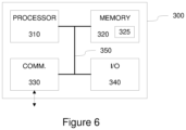
- Figure 6 illustrates a block diagram of some components of an apparatus 300 that may be employed to implement at least some of the operations described with references to the lighting control apparatus 110-k or the sensor control apparatus 140-m.
- the apparatus 300 comprises a processor 310 and a memory 320.
- the memory 320 may store data and computer program code 325.
- the apparatus 300 may further comprise communication means 330 for wired or wireless communication with other apparatuses and/or user I/O (input/output) components 340 that may be arranged, together with the processor 310 and a portion of the computer program code 325, to provide the user interface for receiving input from a user and/or providing output to the user.
- I/O input/output
- the user I/O components may include user input means, such as one or more keys or buttons, a keyboard, a touchscreen or a touchpad, etc.
- the user I/O components may include output means, such as a display or a touchscreen.
- the components of the apparatus 300 are communicatively coupled to each other via a bus 350 that enables transfer of data and control information between the components.
- the computer program code 325 may comprise computer-executable instructions that implement at least some aspects of operation of the lighting control apparatus 110-k or the sensor control apparatus 140-m when loaded into the processor 310.
- the computer program code 325 may include a computer program consisting of one or more sequences of one or more instructions.
- the processor 310 is able to load and execute the computer program by reading the one or more sequences of one or more instructions included therein from the memory 320.
- the one or more sequences of one or more instructions may be configured to, when executed by the processor 310, cause the apparatus 300 to perform at least some aspects of operation of the lighting control apparatus 110-k or the sensor control apparatus 140-m.
- the computer program code 325 may be provided e.g. a computer program product comprising at least one computer-readable non-transitory medium having the computer program code 325 stored thereon, which computer program code 325, when executed by the processor 310 causes the apparatus 300 to perform at least some aspects of operation of the lighting control apparatus 110-k or the sensor control apparatus 140-m.
- the computer-readable non-transitory medium may comprise a memory device or a record medium such as a CD-ROM, a DVD, a Blu-ray disc or another article of manufacture that tangibly embodies the computer program.
- the computer program may be provided as a signal configured to reliably transfer the computer program.
- references(s) to a processor herein should not be understood to encompass only programmable processors, but also dedicated circuits such as field-programmable gate arrays (FPGA), application specific circuits (ASIC), signal processors, etc.
- FPGA field-programmable gate arrays
- ASIC application specific circuits
- signal processors etc.
Landscapes
- Circuit Arrangement For Electric Light Sources In General (AREA)
Claims (15)
- Appareil de commande (110-k, 140-m) d'un nœud (120-k, 145-m) d'un premier réseau qui est agencé pour coupler de manière communicative, entre eux, une pluralité de nœuds (120, 145), ladite pluralité de nœuds (120, 145) comprenant une pluralité de luminaires (120) agencés pour éclairer un ou plusieurs espaces, l'appareil de commande (110-k, 140-m) comprenant :une partie de communication (112-k, 142-m) pour communiquer avec d'autres appareils par l'intermédiaire du premier réseau et d'un deuxième réseau ; etune partie de commande (111-k, 141-k) agencée pour :dériver, sur la base d'un ou plusieurs états d'occupation qui sont associés au nœud (120-k, 145-m), un état d'occupation du nœud qui se rapporte à un emplacement du nœud (120-k, 145-m) dans le ou les espaces et indique l'une d'une occupation ou d'une non-occupation à l'emplacement du nœud ;recevoir, par l'intermédiaire du premier réseau, une ou plusieurs indications d'état provenant d'autres nœuds de la pluralité de nœuds (120, 145) du premier réseau, lesdites indications d'état étant indicatives d'états d'occupation respectifs à des emplacements respectifs desdits autres nœuds de la pluralité d'autres nœuds (120, 145) ;caractérisé en ce que la partie de commande (111-k, 141-k) est agencée pour :dériver, sur la base desdites une ou plusieurs indications d'état, au moins un état d'occupation régional de sorte que chaque état d'occupation régional se rapporte à une pluralité respective d'autres emplacements dans le ou les espaces et indique l'une d'une occupation ou d'une non-occupation à la pluralité respective d'autres emplacements ; etdiffuser, par l'intermédiaire du second réseau, vers un ou plusieurs appareils externes (150) qui sont externes au premier réseau, un message d'état d'occupation du réseau qui indique l'état d'occupation du nœud et l'au moins un état d'occupation régional.
- Appareil (110-k, 140-m) selon la revendication 1, lesdites une ou plusieurs indications d'état comprenant une ou plusieurs des indications suivantes :une ou plusieurs indications d'un luminaire respectif de la pluralité de luminaires (120) allumant sa sortie lumineuse ;une ou plusieurs indications d'un luminaire respectif de la pluralité de luminaires (120) ajustant sa sortie lumineuse à une intensité lumineuse de veille ;une ou plusieurs indications d'un état d'occupation respectif dérivé à un nœud respectif de la pluralité de nœuds (120, 145) du premier réseau ;
- Appareil (110-k, 140-m) selon la revendication 1 ou 2, la partie de commande (111-k, 141-m) étant agencée pour dériver l'état d'occupation du nœud sur la base d'un ou de plusieurs parmi un état d'occupation local et des états d'occupation à distance respectifs dérivés pour ceux de la pluralité de nœuds (120, 145) qui sont affectés à un même groupe avec le nœud (120-k, 145-m), la partie de commande d'éclairage (111-k) étant agencée pour :dériver l'état d'occupation local sur la base d'un signal de capteur reçu d'un capteur d'occupation agencé pour surveiller l'occupation à l'emplacement du nœud (120-k, 145-m),dériver, sur la base d'indications d'état respectives provenant de celle-ci, les états d'occupation à distance respectifs dérivés pour ceux de la pluralité de nœuds (120, 145) qui sont affectés au même groupe que le nœud (120-k, 145-m).
- Appareil (110-k, 140-m) selon l'une quelconque des revendications 1 à 3, l'au moins un état d'occupation régional comprenant un état d'occupation de réseau et la partie de commande (111-k, 141-m) étant agencée pour :dériver un état d'occupation à distance respectif pour lesdits autres nœuds de la pluralité de nœuds (120, 145) sur la base d'une ou plusieurs indications d'état reçues de ceux-ci ; etdériver l'état d'occupation de réseau sur la base des états d'occupation à distance respectifs.
- Appareil (110-k, 140-m) selon l'une quelconque des revendications 1 à 4, l'au moins un état d'occupation régional comprenant un ou plusieurs états d'occupation de groupe de proximité et la partie de commande (111-k, 141-m) étant agencée pour :dériver, sur la base d'une ou plusieurs indications d'état provenant de celle-ci, un état d'occupation à distance respectif pour ces autres nœuds de la pluralité de nœuds (120, 145) qui se trouvent dans une ou plusieurs plages de distance prédéfinies par rapport au nœud (120-k, 145-m) ; etdériver, sur la base des états d'occupation à distance obtenus, l'état d'occupation du groupe de proximité respectif pour ces autres nœuds de la pluralité de nœuds (120, 145) qui se trouvent dans la plage respective desdites une ou plusieurs plages de distance prédéfinies par rapport au nœud (120-k, 145-m).
- Appareil (110-k, 140-m) selon la revendication 5, l'un ou les deux éléments suivants s'appliquant :la ou les indications d'état étant reçues dans un ou plusieurs messages d'état par l'intermédiaire d'un réseau sans fil et la partie de commande (111-k, 141-m) étant agencée pour estimer la distance entre le nœud (120-k, 145-m) et un autre nœud de la pluralité de nœuds (120, 145) sur la base d'indications respectives de puissance de signal reçu, RSSI, dérivées sur la base d'un ou plusieurs messages d'état reçus de l'autre nœud respectif de la pluralité de nœuds (120, 145) ;la ou les indications d'état étant reçues dans un ou plusieurs messages d'état par l'intermédiaire d'un réseau maillé sans fil et la partie de commande (111-k, 141-m) étant agencée pour estimer la distance entre le nœud (120-k, 145-m) et un autre de la pluralité de nœuds (120, 145) sur la base des nombres de sauts respectifs indiqués dans un ou plusieurs messages d'état provenant de l'autre nœud respectif de la pluralité de nœuds (120, 145).
- Appareil (110-k, 140-m) selon l'une quelconque des revendications 1 à 6, l'au moins un état d'occupation régional comprenant un ou plusieurs états d'occupation de groupe spatial et la partie de commande (111-k, 145-m) étant agencée pour :dériver, sur la base des indications d'état respectives provenant de celle-ci, un état d'occupation distant respectif pour ces autres nœuds de la pluralité de nœuds (120, 145) qui sont affectés à l'un quelconque d'un ou de plusieurs groupes spatiaux ; etdériver, pour chaque groupe spatial, l'état d'occupation du groupe spatial respectif sur la base des états d'occupation à distance respectifs dérivés pour ces autres nœuds de la pluralité de nœuds (120, 145) qui sont affectés à l'un groupe respectif du ou des groupes spatiaux.
- Appareil (110-k, 140-m) selon l'une quelconque des revendications 1 à 7, la ou les indications d'état étant reçues par l'intermédiaire d'un réseau maillé Bluetooth à faible énergie.
- Appareil (110-k, 140-m) selon l'une quelconque des revendications 1 à 8, la partie de commande (111-k, 141-m) étant agencée pour diffuser le message d'état d'occupation du réseau dans une unité de données de protocole publicitaire Bluetooth à faible énergie.
- Appareil (110-k, 140-m) selon l'une quelconque des revendications 1 à 9, la partie de commande (111-k, 141-k) étant agencée pour :recevoir, par l'intermédiaire du second réseau, une demande d'inclusion de types spécifiques respectifs d'indications d'occupation en tant qu'état d'occupation du nœud et au moins un état d'occupation régional dans le message d'état d'occupation du réseau ; etcomposer au moins un message d'état d'occupation du réseau ultérieur en fonction de ladite demande.
- Appareil (110-k, 140-m) selon l'une quelconque des revendications 1 à 10, l'appareil de commande (110-k, 140-m) comprenant l'un des éléments suivants :un appareil de commande d'éclairage (110-k) pour un luminaire (120-k) de ladite pluralité de luminaires (120), la partie de commande comprenant une partie de commande d'éclairage (111-k) agencée en outre pour commander un ou plusieurs aspects de la sortie de lumière d'au moins une source (121-k) du luminaire (120-k) ; ouun appareil de commande de capteur (140-m) pour une unité de capteur (145-m) couplée par l'intermédiaire du premier réseau à ladite pluralité de luminaires (120), la partie de commande comprenant une partie de commande de capteur (141-m).
- Luminaire (120-k) comprenant un appareil de commande (111-k) selon l'une quelconque des revendications 1 à 11 et au moins une source de lumière (121-k), la partie de commande comprenant une partie de commande d'éclairage (111-k) agencée en outre pour commander un ou des aspects de la sortie de lumière de l'au moins une source (121-k).
- Luminaire (120-k) selon la revendication 12, comprenant en outre une partie capteur (123-k) comprenant un capteur d'occupation agencé pour fournir à la partie de commande d'éclairage (111-k) un signal de capteur qui est descriptif de l'occupation à l'emplacement du luminaire (120-k).
- Procédé (200) dans un nœud (120-k, 145-m) d'un premier réseau qui est agencé pour coupler communicativement, entre eux, une pluralité de nœuds (120, 145), ladite pluralité de nœuds (120, 145) comprenant une pluralité de luminaires (120) agencés pour éclairer un ou plusieurs espaces, le procédé (200) comprenant :la dérivation (202), sur la base d'un ou plusieurs états d'occupation associés au nœud (120-k, 145-m), d'un état d'occupation du nœud qui se rapporte à un emplacement du nœud (120-k, 145-m) dans le ou les espaces et indique l'une d'une occupation ou d'une non-occupation à l'emplacement du nœud ; etla réception (204), par l'intermédiaire du premier réseau, d'une ou plusieurs indications d'état provenant d'autres nœuds de la pluralité de nœuds (120, 145) du premier réseau, lesdites indications d'état étant indicatives d'états d'occupation respectifs à des emplacements respectifs desdits autres nœuds de la pluralité d'autres nœuds (120, 145) ;caractérisé en ce que le procédé (200) comprend :la dérivation (206), sur la base desdites une ou plusieurs indications d'état, d'au moins un état d'occupation régional de sorte que chaque état d'occupation régional se rapporte à une pluralité respective d'autres emplacements dans le ou les espaces et indique l'une d'une occupation ou d'une non-occupation à la pluralité respective d'autres emplacements ; etla diffusion (208), par l'intermédiaire d'un second réseau, vers un ou plusieurs appareils externes (150) qui sont externes au premier réseau, d'un message d'état d'occupation du réseau indiquant l'état d'occupation du nœud et au moins un état d'occupation régional.
- Programme informatique comprenant un code de programme lisible par ordinateur (325) configuré pour provoquer la réalisation d'au moins le procédé (200) selon la revendication 14 lorsque ledit code de programme (325) est exécuté sur un appareil informatique (300) pourvu d'un moyen de communication (330) pour la communication filaire ou sans fil avec d'autres appareils.
Priority Applications (1)
| Application Number | Priority Date | Filing Date | Title |
|---|---|---|---|
| EP21160191.9A EP4054295B1 (fr) | 2021-03-02 | 2021-03-02 | Partage d'informations d'état de réseau de commande d'éclairage |
Applications Claiming Priority (1)
| Application Number | Priority Date | Filing Date | Title |
|---|---|---|---|
| EP21160191.9A EP4054295B1 (fr) | 2021-03-02 | 2021-03-02 | Partage d'informations d'état de réseau de commande d'éclairage |
Publications (3)
| Publication Number | Publication Date |
|---|---|
| EP4054295A1 EP4054295A1 (fr) | 2022-09-07 |
| EP4054295C0 EP4054295C0 (fr) | 2025-06-25 |
| EP4054295B1 true EP4054295B1 (fr) | 2025-06-25 |
Family
ID=74856604
Family Applications (1)
| Application Number | Title | Priority Date | Filing Date |
|---|---|---|---|
| EP21160191.9A Active EP4054295B1 (fr) | 2021-03-02 | 2021-03-02 | Partage d'informations d'état de réseau de commande d'éclairage |
Country Status (1)
| Country | Link |
|---|---|
| EP (1) | EP4054295B1 (fr) |
Cited By (1)
| Publication number | Priority date | Publication date | Assignee | Title |
|---|---|---|---|---|
| US20240365459A1 (en) * | 2020-09-18 | 2024-10-31 | Lutron Technology Company Llc | Load control system comprising linear lighting fixtures |
Family Cites Families (3)
| Publication number | Priority date | Publication date | Assignee | Title |
|---|---|---|---|---|
| EP2935988B1 (fr) * | 2012-12-18 | 2019-01-30 | Cree, Inc. | Appareil d'éclairage pour commande distribuée |
| US9820361B1 (en) * | 2016-07-20 | 2017-11-14 | Abl Ip Holding Llc | Wireless lighting control system |
| US10334707B1 (en) * | 2017-12-13 | 2019-06-25 | Abl Ip Holding Llc | Heuristic occupancy and non-occupancy detection in a lighting system with a single transmitter and multiple receivers |
-
2021
- 2021-03-02 EP EP21160191.9A patent/EP4054295B1/fr active Active
Cited By (1)
| Publication number | Priority date | Publication date | Assignee | Title |
|---|---|---|---|---|
| US20240365459A1 (en) * | 2020-09-18 | 2024-10-31 | Lutron Technology Company Llc | Load control system comprising linear lighting fixtures |
Also Published As
| Publication number | Publication date |
|---|---|
| EP4054295C0 (fr) | 2025-06-25 |
| EP4054295A1 (fr) | 2022-09-07 |
Similar Documents
| Publication | Publication Date | Title |
|---|---|---|
| US12041513B2 (en) | Determining a suitability of network nodes for RF-based presence and/or location detection | |
| US20250202603A1 (en) | Assigning router devices in a mesh network | |
| JP7163507B2 (ja) | Rfベースの存在及び/又は位置検出機能を備えるノードを避けるネットワークルートの決定 | |
| US12143319B2 (en) | Time-varying allocation to RF-based presence detection and/or localization and message reception | |
| EP3937439A1 (fr) | Adressage de réseau maillé | |
| US12408200B2 (en) | Control device having an adaptive transmission threshold | |
| EP4054295B1 (fr) | Partage d'informations d'état de réseau de commande d'éclairage | |
| EP3846591B1 (fr) | Commande d'éclairage | |
| US11334038B2 (en) | Automation system | |
| EP4203624A1 (fr) | Commande d'éclairage | |
| EP4203623A1 (fr) | Commande d'éclairage | |
| FI129261B (en) | Lighting control | |
| EP4376555A1 (fr) | Commande d'éclairage | |
| EP3758448A1 (fr) | Commande d'éclairage auto-adaptative | |
| US20230276558A1 (en) | Lighting Control | |
| EP4516063B1 (fr) | Procédé permettant d'associer un premier type de dispositif de noeud et un second type de dispositif de noeud dans un réseau | |
| EP3749060B1 (fr) | Commande d'éclairage à configuration automatique | |
| WO2025179243A1 (fr) | Mise à jour de rôles et/ou relations de dispositifs dans un réseau maillé |
Legal Events
| Date | Code | Title | Description |
|---|---|---|---|
| PUAI | Public reference made under article 153(3) epc to a published international application that has entered the european phase |
Free format text: ORIGINAL CODE: 0009012 |
|
| STAA | Information on the status of an ep patent application or granted ep patent |
Free format text: STATUS: THE APPLICATION HAS BEEN PUBLISHED |
|
| AK | Designated contracting states |
Kind code of ref document: A1 Designated state(s): AL AT BE BG CH CY CZ DE DK EE ES FI FR GB GR HR HU IE IS IT LI LT LU LV MC MK MT NL NO PL PT RO RS SE SI SK SM TR |
|
| STAA | Information on the status of an ep patent application or granted ep patent |
Free format text: STATUS: REQUEST FOR EXAMINATION WAS MADE |
|
| 17P | Request for examination filed |
Effective date: 20230307 |
|
| RBV | Designated contracting states (corrected) |
Designated state(s): AL AT BE BG CH CY CZ DE DK EE ES FI FR GB GR HR HU IE IS IT LI LT LU LV MC MK MT NL NO PL PT RO RS SE SI SK SM TR |
|
| STAA | Information on the status of an ep patent application or granted ep patent |
Free format text: STATUS: EXAMINATION IS IN PROGRESS |
|
| 17Q | First examination report despatched |
Effective date: 20240422 |
|
| GRAP | Despatch of communication of intention to grant a patent |
Free format text: ORIGINAL CODE: EPIDOSNIGR1 |
|
| STAA | Information on the status of an ep patent application or granted ep patent |
Free format text: STATUS: GRANT OF PATENT IS INTENDED |
|
| INTG | Intention to grant announced |
Effective date: 20250227 |
|
| GRAS | Grant fee paid |
Free format text: ORIGINAL CODE: EPIDOSNIGR3 |
|
| GRAA | (expected) grant |
Free format text: ORIGINAL CODE: 0009210 |
|
| STAA | Information on the status of an ep patent application or granted ep patent |
Free format text: STATUS: THE PATENT HAS BEEN GRANTED |
|
| AK | Designated contracting states |
Kind code of ref document: B1 Designated state(s): AL AT BE BG CH CY CZ DE DK EE ES FI FR GB GR HR HU IE IS IT LI LT LU LV MC MK MT NL NO PL PT RO RS SE SI SK SM TR |
|
| REG | Reference to a national code |
Ref country code: GB Ref legal event code: FG4D |
|
| REG | Reference to a national code |
Ref country code: CH Ref legal event code: EP |
|
| REG | Reference to a national code |
Ref country code: CH Ref legal event code: EP |
|
| REG | Reference to a national code |
Ref country code: IE Ref legal event code: FG4D |
|
| REG | Reference to a national code |
Ref country code: DE Ref legal event code: R096 Ref document number: 602021032673 Country of ref document: DE |
|
| U01 | Request for unitary effect filed |
Effective date: 20250722 |
|
| U07 | Unitary effect registered |
Designated state(s): AT BE BG DE DK EE FI FR IT LT LU LV MT NL PT RO SE SI Effective date: 20250730 |
|
| PG25 | Lapsed in a contracting state [announced via postgrant information from national office to epo] |
Ref country code: GR Free format text: LAPSE BECAUSE OF FAILURE TO SUBMIT A TRANSLATION OF THE DESCRIPTION OR TO PAY THE FEE WITHIN THE PRESCRIBED TIME-LIMIT Effective date: 20250926 Ref country code: NO Free format text: LAPSE BECAUSE OF FAILURE TO SUBMIT A TRANSLATION OF THE DESCRIPTION OR TO PAY THE FEE WITHIN THE PRESCRIBED TIME-LIMIT Effective date: 20250925 |
|
| PG25 | Lapsed in a contracting state [announced via postgrant information from national office to epo] |
Ref country code: HR Free format text: LAPSE BECAUSE OF FAILURE TO SUBMIT A TRANSLATION OF THE DESCRIPTION OR TO PAY THE FEE WITHIN THE PRESCRIBED TIME-LIMIT Effective date: 20250625 |
|
| PG25 | Lapsed in a contracting state [announced via postgrant information from national office to epo] |
Ref country code: RS Free format text: LAPSE BECAUSE OF FAILURE TO SUBMIT A TRANSLATION OF THE DESCRIPTION OR TO PAY THE FEE WITHIN THE PRESCRIBED TIME-LIMIT Effective date: 20250925 |
|
| PG25 | Lapsed in a contracting state [announced via postgrant information from national office to epo] |
Ref country code: IS Free format text: LAPSE BECAUSE OF FAILURE TO SUBMIT A TRANSLATION OF THE DESCRIPTION OR TO PAY THE FEE WITHIN THE PRESCRIBED TIME-LIMIT Effective date: 20251025 |
|
| PG25 | Lapsed in a contracting state [announced via postgrant information from national office to epo] |
Ref country code: SM Free format text: LAPSE BECAUSE OF FAILURE TO SUBMIT A TRANSLATION OF THE DESCRIPTION OR TO PAY THE FEE WITHIN THE PRESCRIBED TIME-LIMIT Effective date: 20250625 |
|
| PG25 | Lapsed in a contracting state [announced via postgrant information from national office to epo] |
Ref country code: CZ Free format text: LAPSE BECAUSE OF FAILURE TO SUBMIT A TRANSLATION OF THE DESCRIPTION OR TO PAY THE FEE WITHIN THE PRESCRIBED TIME-LIMIT Effective date: 20250625 |
|
| PG25 | Lapsed in a contracting state [announced via postgrant information from national office to epo] |
Ref country code: PL Free format text: LAPSE BECAUSE OF FAILURE TO SUBMIT A TRANSLATION OF THE DESCRIPTION OR TO PAY THE FEE WITHIN THE PRESCRIBED TIME-LIMIT Effective date: 20250625 |
|
| PG25 | Lapsed in a contracting state [announced via postgrant information from national office to epo] |
Ref country code: SK Free format text: LAPSE BECAUSE OF FAILURE TO SUBMIT A TRANSLATION OF THE DESCRIPTION OR TO PAY THE FEE WITHIN THE PRESCRIBED TIME-LIMIT Effective date: 20250625 |
|
| PG25 | Lapsed in a contracting state [announced via postgrant information from national office to epo] |
Ref country code: ES Free format text: LAPSE BECAUSE OF FAILURE TO SUBMIT A TRANSLATION OF THE DESCRIPTION OR TO PAY THE FEE WITHIN THE PRESCRIBED TIME-LIMIT Effective date: 20250625 |
|
| PGFP | Annual fee paid to national office [announced via postgrant information from national office to epo] |
Ref country code: GB Payment date: 20260327 Year of fee payment: 6 |
|
| PLBE | No opposition filed within time limit |
Free format text: ORIGINAL CODE: 0009261 |
|
| STAA | Information on the status of an ep patent application or granted ep patent |
Free format text: STATUS: NO OPPOSITION FILED WITHIN TIME LIMIT |