EP4054360B1 - Dispositif vaporisateur - Google Patents
Dispositif vaporisateur Download PDFInfo
- Publication number
- EP4054360B1 EP4054360B1 EP20816723.9A EP20816723A EP4054360B1 EP 4054360 B1 EP4054360 B1 EP 4054360B1 EP 20816723 A EP20816723 A EP 20816723A EP 4054360 B1 EP4054360 B1 EP 4054360B1
- Authority
- EP
- European Patent Office
- Prior art keywords
- cartridge
- vaporizer
- vaporizable material
- receptacle
- vaporizer device
- Prior art date
- Legal status (The legal status is an assumption and is not a legal conclusion. Google has not performed a legal analysis and makes no representation as to the accuracy of the status listed.)
- Active
Links
Images









Classifications
-
- A—HUMAN NECESSITIES
- A24—TOBACCO; CIGARS; CIGARETTES; SIMULATED SMOKING DEVICES; SMOKERS' REQUISITES
- A24F—SMOKERS' REQUISITES; MATCH BOXES; SIMULATED SMOKING DEVICES
- A24F40/00—Electrically operated smoking devices; Component parts thereof; Manufacture thereof; Maintenance or testing thereof; Charging means specially adapted therefor
- A24F40/40—Constructional details, e.g. connection of cartridges and battery parts
- A24F40/48—Fluid transfer means, e.g. pumps
-
- A—HUMAN NECESSITIES
- A24—TOBACCO; CIGARS; CIGARETTES; SIMULATED SMOKING DEVICES; SMOKERS' REQUISITES
- A24F—SMOKERS' REQUISITES; MATCH BOXES; SIMULATED SMOKING DEVICES
- A24F40/00—Electrically operated smoking devices; Component parts thereof; Manufacture thereof; Maintenance or testing thereof; Charging means specially adapted therefor
- A24F40/10—Devices using liquid inhalable precursors
-
- A—HUMAN NECESSITIES
- A24—TOBACCO; CIGARS; CIGARETTES; SIMULATED SMOKING DEVICES; SMOKERS' REQUISITES
- A24F—SMOKERS' REQUISITES; MATCH BOXES; SIMULATED SMOKING DEVICES
- A24F40/00—Electrically operated smoking devices; Component parts thereof; Manufacture thereof; Maintenance or testing thereof; Charging means specially adapted therefor
- A24F40/40—Constructional details, e.g. connection of cartridges and battery parts
-
- A—HUMAN NECESSITIES
- A24—TOBACCO; CIGARS; CIGARETTES; SIMULATED SMOKING DEVICES; SMOKERS' REQUISITES
- A24F—SMOKERS' REQUISITES; MATCH BOXES; SIMULATED SMOKING DEVICES
- A24F40/00—Electrically operated smoking devices; Component parts thereof; Manufacture thereof; Maintenance or testing thereof; Charging means specially adapted therefor
- A24F40/40—Constructional details, e.g. connection of cartridges and battery parts
- A24F40/42—Cartridges or containers for inhalable precursors
-
- A—HUMAN NECESSITIES
- A24—TOBACCO; CIGARS; CIGARETTES; SIMULATED SMOKING DEVICES; SMOKERS' REQUISITES
- A24F—SMOKERS' REQUISITES; MATCH BOXES; SIMULATED SMOKING DEVICES
- A24F40/00—Electrically operated smoking devices; Component parts thereof; Manufacture thereof; Maintenance or testing thereof; Charging means specially adapted therefor
- A24F40/40—Constructional details, e.g. connection of cartridges and battery parts
- A24F40/44—Wicks
-
- A—HUMAN NECESSITIES
- A24—TOBACCO; CIGARS; CIGARETTES; SIMULATED SMOKING DEVICES; SMOKERS' REQUISITES
- A24F—SMOKERS' REQUISITES; MATCH BOXES; SIMULATED SMOKING DEVICES
- A24F40/00—Electrically operated smoking devices; Component parts thereof; Manufacture thereof; Maintenance or testing thereof; Charging means specially adapted therefor
- A24F40/40—Constructional details, e.g. connection of cartridges and battery parts
- A24F40/46—Shape or structure of electric heating means
-
- A—HUMAN NECESSITIES
- A24—TOBACCO; CIGARS; CIGARETTES; SIMULATED SMOKING DEVICES; SMOKERS' REQUISITES
- A24F—SMOKERS' REQUISITES; MATCH BOXES; SIMULATED SMOKING DEVICES
- A24F40/00—Electrically operated smoking devices; Component parts thereof; Manufacture thereof; Maintenance or testing thereof; Charging means specially adapted therefor
- A24F40/40—Constructional details, e.g. connection of cartridges and battery parts
- A24F40/48—Fluid transfer means, e.g. pumps
- A24F40/485—Valves; Apertures
-
- A—HUMAN NECESSITIES
- A24—TOBACCO; CIGARS; CIGARETTES; SIMULATED SMOKING DEVICES; SMOKERS' REQUISITES
- A24F—SMOKERS' REQUISITES; MATCH BOXES; SIMULATED SMOKING DEVICES
- A24F40/00—Electrically operated smoking devices; Component parts thereof; Manufacture thereof; Maintenance or testing thereof; Charging means specially adapted therefor
- A24F40/60—Devices with integrated user interfaces
-
- A—HUMAN NECESSITIES
- A24—TOBACCO; CIGARS; CIGARETTES; SIMULATED SMOKING DEVICES; SMOKERS' REQUISITES
- A24F—SMOKERS' REQUISITES; MATCH BOXES; SIMULATED SMOKING DEVICES
- A24F40/00—Electrically operated smoking devices; Component parts thereof; Manufacture thereof; Maintenance or testing thereof; Charging means specially adapted therefor
- A24F40/65—Devices with integrated communication means, e.g. wireless communication means
-
- A—HUMAN NECESSITIES
- A24—TOBACCO; CIGARS; CIGARETTES; SIMULATED SMOKING DEVICES; SMOKERS' REQUISITES
- A24F—SMOKERS' REQUISITES; MATCH BOXES; SIMULATED SMOKING DEVICES
- A24F40/00—Electrically operated smoking devices; Component parts thereof; Manufacture thereof; Maintenance or testing thereof; Charging means specially adapted therefor
- A24F40/90—Arrangements or methods specially adapted for charging batteries thereof
-
- H—ELECTRICITY
- H01—ELECTRIC ELEMENTS
- H01F—MAGNETS; INDUCTANCES; TRANSFORMERS; SELECTION OF MATERIALS FOR THEIR MAGNETIC PROPERTIES
- H01F7/00—Magnets
-
- A—HUMAN NECESSITIES
- A24—TOBACCO; CIGARS; CIGARETTES; SIMULATED SMOKING DEVICES; SMOKERS' REQUISITES
- A24F—SMOKERS' REQUISITES; MATCH BOXES; SIMULATED SMOKING DEVICES
- A24F40/00—Electrically operated smoking devices; Component parts thereof; Manufacture thereof; Maintenance or testing thereof; Charging means specially adapted therefor
- A24F40/50—Control or monitoring
-
- A—HUMAN NECESSITIES
- A24—TOBACCO; CIGARS; CIGARETTES; SIMULATED SMOKING DEVICES; SMOKERS' REQUISITES
- A24F—SMOKERS' REQUISITES; MATCH BOXES; SIMULATED SMOKING DEVICES
- A24F40/00—Electrically operated smoking devices; Component parts thereof; Manufacture thereof; Maintenance or testing thereof; Charging means specially adapted therefor
- A24F40/70—Manufacture
Definitions
- the vaporizable material can be drawn out of a reservoir and into the vaporization chamber via a wicking element (a wick).
- a wicking element a wick
- Such drawing of the vaporizable material into the vaporization chamber can be due, at least in part, to capillary action provided by the wick, which pulls the vaporizable material along the wick in the direction of the vaporization chamber.
- the pressure inside the reservoir is reduced, thereby creating a vacuum and acting against the capillary action.
- Control in this context, refers generally to an ability to influence one or more of a variety of operating parameters, which may include without limitation any of causing the heater to be turned on and/or off, adjusting a minimum and/or maximum temperature to which the heater is heated during operation, other interactive features that a user might access on a device, and/or other operations.
- vaporizable materials having a variety of contents and proportions of such contents can be contained in the cartridge.
- Some vaporizable materials may have a smaller percentage of active ingredients per total volume of vaporizable material, such as due to regulations requiring certain active ingredient percentages.
- a user may need to vaporize a large amount of vaporizable material (e.g., compared to the overall volume of vaporizable material that can be stored in a cartridge) to achieve a desired effect.
- EP 3 488 715 A2 discloses a vaporizer device comprising a shell, a cartridge receptacle and a skeleton, wherein the vaporizer device is configured to form an electrical coupling with a vaporizer cartridge.
- US 2019/099561 A1 , CN 110 226 778 A , and US 2019/166913 A1 disclose further examples of vaporizer devices.
- the vaporizer device may further include a battery and a printed circuit board assembly including a controller of the vaporizer device.
- the printed circuit board assembly may be coupled to the battery and the cartridge interface to form a first assembly.
- the first assembly may be coupled to the skeleton to form a second assembly that is disposed inside the shell.
- the shell may be formed from a first material.
- the vaporizer device may further include an endcap formed from a second material that is more penetrable to radio waves from the antenna than the first material.
- the endcap may be configured to seal an open end of the shell opposite to the cartridge receptacle.
- the cartridge interface includes a set of receptacle contacts configured to form the first electrical coupling with a set of heater contacts of the heating element of the vaporizer cartridge.
- the set of receptacle contacts may include two pairs of electrical contacts disposed at opposite sides of the cartridge receptacle.
- the cartridge interface further includes a set of cartridge identifier contacts configured to form the second electrical coupling with a corresponding set of cartridge identifier contacts at the cartridge identification chip of the vaporizer device.
- the set of cartridge identifier contacts includes a first set of three electrical contacts disposed at one side of the cartridge receptacle and a second set of three electrical contacts disposed at an opposite side of the cartridge receptacle.
- the set of cartridge identifier contacts may include at least one electrical contact that is preloaded to exert a force against a corresponding electrical contact at the cartridge identification chip.
- the sheath may be configured to prevent an overextension of the at least one electrical contact.
- the sheath may be further configured to prevent contact between the at least one electrical contact and the shell of the vaporizer device.
- the sheath and the shell may be formed as a solitary unit.
- the sheath may be coupled to the shell by one or more of an adhesive, a friction fit, and/or a welding.
- the cartridge interface may be further configured to form, with the vaporizer cartridge, a mechanical coupling configured to retain the vaporizer cartridge inside the cartridge receptacle.
- the vaporizer device may further include a first retention feature configured to couple the vaporizer device to a charger device.
- the first retention feature may be configured to form a magnetic coupling with a second retention feature at the charger device.
- the magnetic coupling may align and maintain the vaporizer device in one or more position and/or orientation relative to the charger device.
- the wicking element 1362 is generally configured to draw the liquid vaporizable material 1302 from the reservoir 140 containing the liquid vaporizable material 1302 such that the liquid vaporizable material 1302 may be vaporized by heat generated by the heating element 1350.
- Air may enter the reservoir 140 to replace the volume of liquid vaporizable material 1302 drawn out of the reservoir 140, for example, by the wicking element 1362.
- capillary action may pull liquid vaporizable material 1302 into the wicking element 1362 for vaporization by heat generated by the heating element 1350, and air may, in some implementations of the current subject matter, return to the reservoir 140 to at least partially equalize pressure in the reservoir 140.
- Various approaches for allowing air to enter the reservoir 140 to equalize pressure are within the scope of the current subject matter as discussed in greater detail below.
- the heating element 1350 can configured to deliver heat to the wicking element 1362, for example, by being wrapped at least partially around, positioned at least partially within, at least partially integrated into a bulk shape of, and/or positioned in at least partial thermal contact with the wicking element 1362.
- Heat delivered to the wicking element 1362 may cause at least a portion of the liquid vaporizable material 1302 drawn into the wicking element 1362 from the reservoir 140 to be vaporized for subsequent inhalation by a user in a gas phase and/or a condensed (e.g., aerosol particles or droplets) phase.
- the wicking element 1362 and the heating element 1350 may be configured in various manners in order to form the atomizer 141.
- the vaporizer device 100 may also be configured to heat a non-liquid formulation of the vaporizable material 1302 to generate an inhalable dose of the vaporizable material 1302 in a gas-phase and/or an aerosol-phase.
- non-liquid formulations of the vaporizable material 1302 include a solid-phase vaporizable material (e.g., a wax or the like) or a plant material (e.g., tobacco leaves and/or parts of tobacco leaves).
- the heating element 1350 may be part of or otherwise incorporated into or in thermal contact with the walls of a heating chamber (e.g., an oven and/or the like) into which the non-liquid vaporizable material 1302 is placed.
- the heating element 1350 may be used to heat air passing through or past the non-liquid vaporizable material 1302 to cause convective heating of the non-liquid vaporizable material 1302.
- the heating element 1350 may be a resistive heating element disposed in intimate contact with non-liquid vaporizable material 1302 such that direct conductive heating of the non-liquid vaporizable material 1302 occurs from within a mass of the non-liquid vaporizable material 1302 (e.g., as opposed to by conduction inward from the walls of a heating chamber).
- the vaporizer device 100 may deliver, to the heating element 1350, electrical power from the power source 112 (e.g., a battery and/or the like).
- the delivery of electrical power to the heating element 1350 may be controlled by the controller 104.
- electrical power may be delivered to the heating element 1350 by discharging a current from the power source 112 through a circuit including the heating element 1350.
- the controller 104 may activate the heating element 1350, for example, by causing the power source 112 to deliver electrical power (e.g., discharge current) to the heating element 1350, in response to a user puffing (e.g., drawing, inhaling, and/or the like) on a mouthpiece 1330 of the vaporizer device 100.
- the user puffing on the mouthpiece of the vaporizer device 100 may cause air to flow from an air inlet, along an airflow path that traverses the atomizer 141 including the heating element 1350 and the wicking element 1362, and optionally through one or more condensation areas or chambers, to an air outlet in the mouthpiece 1330.
- Incoming air passing along the airflow path may pass over or through the atomizer 141, where the vaporizable material 1302 in the gas phase may be entrained into the air.
- the entrained gas-phase vaporizable material 1302 may condense as it passes through the remainder of the airflow path such that an inhalable dose of the vaporizable material 1302 in an aerosol form can be delivered from the air outlet disposed in the mouthpiece 1330 for inhalation by a user.
- the heating element 1350 can be activated in response to a user puffing (i.e., drawing, inhaling, etc.) on a mouthpiece 1330 of the vaporizer device 100 to cause air to flow from an air inlet, along an airflow path that passes the atomizer 141 including the wicking element 1362 and the heating element 1350.
- air can flow from an air inlet through one or more condensation areas or chambers, to an air outlet in the mouthpiece 1330.
- Incoming air moving along the airflow path moves over or through the atomizer 141, where the vaporizable material 1302 in the gas phase is entrained into the air.
- the heating element 1350 can be activated via the controller 104, which can optionally be a part of a vaporizer body 110 as discussed herein, causing current to pass from the power source 112 through a circuit including the heating element 1350. Although shown as a part of a vaporizer cartridge 1320, it should be appreciated that the at least a portion of the atomizer 141 including the heating element 1350 may also be disposed in the vaporizer body 110.
- the entrained vaporizable material 1302 in the gas phase can condense as it passes through the remainder of the airflow path such that an inhalable dose of the vaporizable material 1302 in an aerosol form can be delivered from the air outlet (for example, the mouthpiece 1330) for inhalation by a user.
- the heating element 1350 may be activated by the controller 104 in response to the controller detecting an occurrence (or an imminent occurrence) of a puff based on one or more signals received from the sensors 113.
- the sensors 113 can include one or more of a pressure sensor configured to detect pressure along the airflow path and/or an ambient pressure, a motion sensor (e.g., an accelerometer) configured to detect a movement of the vaporizer device 100, a flow sensor, a capacitive sensor configured to detect interaction between a user and the vaporizer device 100, and/or the like.
- the occurrence of a puff and/or the imminent occurrence of a puff may be detected based on a user interaction with one or more input devices 116 (e.g., buttons or other tactile control devices of the vaporizer device 100), one or more signals from a computing device in communication with the vaporizer device 100, and/or the like.
- one or more input devices 116 e.g., buttons or other tactile control devices of the vaporizer device 100
- one or more signals from a computing device in communication with the vaporizer device 100 may be detected based on a user interaction with one or more input devices 116 (e.g., buttons or other tactile control devices of the vaporizer device 100), one or more signals from a computing device in communication with the vaporizer device 100, and/or the like.
- the vaporizer device 100 may be configured to connect (e.g., wirelessly or via a wired connection) to a computing device (or optionally two or more devices) in communication with the vaporizer.
- the controller 104 may include communication hardware 105.
- the controller 104 may also include a memory 108.
- a computing device can be a component of a vaporizer system that also includes the vaporizer device 100, and can include its own communication hardware, which can establish a wireless communication channel with the communication hardware 105 of the vaporizer device 100.
- a computing device used as part of a vaporizer system may include a general purpose computing device (e.g., a smartphone, a tablet, a personal computer, some other portable device such as a smartwatch, or the like) that executes software to produce a user interface for enabling a user of the device to interact with a vaporizer.
- a general purpose computing device e.g., a smartphone, a tablet, a personal computer, some other portable device such as a smartwatch, or the like
- a general purpose computing device e.g., a smartphone, a tablet, a personal computer, some other portable device such as a smartwatch, or the like
- the computing device may execute one or more computer instructions sets to provide a user interface and underlying data handling.
- detection by the computing device of user interaction with one or more user interface elements can cause the computing device to signal the vaporizer device 100 to activate the heating element 1350, either to a full operating temperature for creation of an inhalable dose of vapor/aerosol.
- Other functions of the vaporizer may be controlled by interaction of a user with a user interface on a computing device in communication with the vaporizer device 100.
- the sensors 113 e.g., the pressure sensor, the motion sensor, the capacitive sensor, and/or the like
- the controller 104 e.g., a printed circuit board assembly or other type of circuit board.
- a resilient seal 150 may optionally separate an airflow path from other parts of the vaporizer device 100.
- the seal 150 which can be a gasket, may be configured to at least partially surround the pressure sensor such that connections of the pressure sensor to internal circuitry of the vaporizer device 100 are separated from a part of the pressure sensor exposed to the airflow path.
- the seal 150 may also separate parts of one or more electrical connections between a vaporizer body 110 and the vaporizer cartridge 1320 from one or more other parts of the vaporizer body 110.
- Such arrangements of the seal 150 in the vaporizer device 100 can be helpful in mitigating against potentially disruptive impacts on vaporizer components resulting from interactions with environmental factors such as water in the vapor or liquid phases, other fluids such as the vaporizable material 1302, etc. and/or to reduce escape of air from the designed airflow path in the vaporizer device 100.
- the vaporizer device 100 may be, as noted, a cartridge-based vaporizer configured to couple with, for example, the vaporizer cartridge 1320.
- the power source 112 e.g., battery
- the one more sensors 113 e.g., one or more charging contacts 124, and the seal 150
- FIG. 1 show the vaporizer body 110 of the vaporizer device 100 as including a cartridge receptacle 118 configured to receive at least part of the vaporizer cartridge 1320 for coupling with the vaporizer body 110 through one or more of a variety of attachment structures.
- the vaporizer cartridge 1320 may include the reservoir 140 for containing the vaporizable material 1302 and the mouthpiece 1330 for delivering an inhalable dose to a user.
- the atomizer 141 including, for example, the wicking element 1362 and the heating element 1350, may be disposed at least partially within the vaporizer cartridge 1320.
- the heating element 1350 and/or the wicking element 1362 can be disposed within the vaporizer cartridge 1320 such that walls enclosing the cartridge receptacle 118 surround all or at least part of the heating element 1350 and/or the wicking element 1362 when the vaporizer cartridge 1320 is fully connected to the vaporizer body 110.
- the portion of the vaporizer cartridge 1320 that inserts into the cartridge receptacle 118 of the vaporizer body 110 may be positioned internal to another part of the vaporizer cartridge 1320.
- the insertable part of the vaporizer cartridge 1320 may be at least partially surrounded by some other part, such as for example a housing and/or an outer shell, of the vaporizer cartridge 1320.
- the atomizer 141 may be disposed in the vaporizer body 110 of the vaporizer device 100.
- the vaporizer device 100 can be configured to deliver at least the vaporizer material 1302 from the reservoir 140 in the vaporizer cartridge 1320 to the portions of the atomizer 141 included in the vaporizer body 110.
- This reduced pressure may, in some examples, be sufficiently large in magnitude to reduce the effectiveness of the wicking element 1362 for drawing liquid vaporizable material 1302, thereby reducing the effectiveness of the vaporizer device 100 to vaporize a desired amount of vaporizable material 1302, such as when a user takes a puff on the vaporizer device 100.
- the vacuum created in the reservoir 140 could result in the inability to draw all of the vaporizable material 1302 from the reservoir 140, thereby leading to incomplete usage and waste of the vaporizable material 1302.
- the otherwise empty void volume e.g., space emptied by use of the liquid vaporizable material 1302
- this air-filled void volume may subsequently experience pressure changes relative to ambient air. This pressure change may, under certain conditions, result in the vaporizable material 1302 leaking out of the reservoir 140 and ultimately out of the vaporizer cartridge 1320 and/or other part of the vaporizer device 100 including the reservoir 140.
- the overall resistance of the collector 1313 to allowing liquid to flow out of the collector 1313 may be larger than an overall resistance of the wicking element 1362, for example, to allow the vaporizable material 1302 to primarily flow through the primary passageway 1382 toward the wicking element 1362 during the first pressure state.
- the primary passageway 1382 may provide a capillary pathway through or into the wicking element 1362 for the vaporizable material 1302 stored in reservoir 140.
- the capillary pathway (e.g., the primary passageway 1382) may be large enough to permit a wicking action or capillary action to replace the vaporized vaporizable material 1302 in the wicking element 1362 but small enough to prevent leakage of the vaporizable material 1302 out of the vaporizer cartridge 1320 when excess pressure inside the vaporizer cartridge 1320 displaces at least a portion of the vaporizable material 1302 from the storage chamber 1342.
- the wick housing or the wicking element 1362 may be treated to prevent leakage.
- the vaporizer cartridge 1320 may be coated after filling to prevent leakage or evaporation through the wicking element 1362.
- Any appropriate coating may be used, including, for example, a heat-vaporizable coating (e.g., a wax or other material) and/or the like.
- the heating element 1350 may be activated in response to a signal generated by the one or more sensors 113 (shown in FIG. 1 ).
- the one or more sensors 113 may include at least one of pressure sensor, motion sensor, flow sensor, or other mechanism capable of detecting a puff and/or an imminent puff including, for example, by detecting changes in the airflow passageway 1338.
- activating the heating element 1350 may include the controller 104 (e.g., shown in FIG. 1 ) controlling the power source 112 to discharge an electric current from the power source 112 to the heating element 1350.
- Heat generated by the heating element 1350 may be transferred to at least a portion of the vaporizable material 1302 in the wicking element 1362 through conductive, convective, and/or radiative heat transfer such that at least a portion of the vaporizable material 1302 drawn into the wicking element 1362 is vaporized.
- air entering the vaporizer cartridge 1320 may flow over (or around, near, etc.) the wicking element 1362 and the heated elements in the heating element 1350 and may strip away the vaporized vaporizable material 1302 into the airflow passageway 1338, where the vapor may optionally be condensed and delivered in aerosol form, for example, through the orifice 220 in the mouthpiece area 1330.
- the storage chamber 1342 may be connected to the airflow passageway 1338 (i.e., via the overflow channel 1104 of overflow volume 1344) for the purpose of allowing the portions of the liquid vaporizable material 1302 driven from the storage chamber 1342 by increased pressure in the storage chamber 1342 relative to ambient to be retained in the overflow volume 1344 without escaping from the vaporizer cartridge 1320. While the implementations described herein relate to the vaporizer cartridge 1320 including the reservoir 140, it will be understood that the approaches described are also compatible with and contemplated for use in a vaporizer without a separable cartridge.
- air which may be admitted to the storage chamber 1342 when the pressure inside the vaporizer cartridge 1320 is lower than ambient pressure, may increase the pressure inside the vaporizer cartridge 1320 and may cause the vaporizer cartridge 1320 to transition to the second pressure state in which the pressure inside the vaporizer cartridge 1320 exceed the ambient pressure external to the vaporizer cartridge 1320.
- the vaporizer cartridge 1320 may transition to the second pressure state in response to a change in ambient temperature, a change in ambient pressure (e.g., due to a change in external conditions such as altitude, weather, and/or the like), and/or a change in the volume of the vaporizer cartridge 1320 (e.g., when the vaporizer cartridge 1320 is compacted by an external force such as squeezing).
- the increase in the pressure inside the storage chamber 1342 for example, in the case of a negative pressure event, may at least expand the air occupying the void space of the storage chamber 1342, thereby displacing at least a portion of the liquid vaporizable material 1302 in the storage chamber 1342.
- the microfluidic features can include a cross-sectional area sufficiently small that for the material from which walls of the overflow channel 1104 are formed and the composition of the liquid vaporizable material 1302, the liquid vaporizable material 1302 preferentially wets the overflow channel 1104 around an entire perimeter of the overflow channel 1104.
- the liquid vaporizable material 1302 includes one or more of propylene glycol and vegetable glycerin
- wetting properties of such a liquid are advantageously considered in combination with the geometry of the second passageway 1384 and materials form which the walls of the overflow channel 1104 are formed.
- the vaporizable material 1302 present in the overflow channel 1104 of the collector 1313 may be withdrawn into the storage chamber 1342 sufficiently to cause the leading liquid-air meniscus to reach a gate or port between the overflow channel 1104 of the collector 1313 and the storage chamber 1342.
- the pressure differential in the storage chamber 1342 relative to ambient pressure is sufficiently negative to overcome surface tension maintaining the meniscus at the gate or port, the meniscus may be freed from the gate or port walls to form one or more air bubbles, which are then released into the storage chamber 1342 with sufficient volume to equalize the pressure inside the storage chamber 1342 relative to ambient pressure.
- the column of vaporizable material 1302 may be withdrawn back into the storage chamber 140, and optionally until the meniscus reaches the gate or port. If the pressure differential sufficiently favors ambient pressure relative to the pressure inside the storage chamber 1342, the above-described bubble formation process may occur until the two pressures equalize.
- the collector 1313 may act as a reversible overflow volume that accepts the vaporizable material 1302 that is pushed out of the storage chamber 1342 under transient conditions of greater storage chamber pressure relative to ambient pressure while allowing at least some (and desirably all or most) of this overflow volume of vaporizable material 1302 to be returned to the storage chamber 140 for later delivery, for example, to the heating element 1350 for conversion to an inhalable aerosol.
- the storage chamber 1342 may or may not be connected to the wicking element 1362 via the overflow channel 1104.
- the overflow channel 1104 includes a first end coupled with the storage chamber 1342 and a second end overflow channel 1104 leading to the wicking element 1362, any of the vaporizable material 1302 that may exit the overflow channel 1104 at the second end may further saturate the wicking element 1362.
- the storage chamber 1342 may optionally be positioned closer to an end of the reservoir 140 that is near the mouthpiece area 1330.
- the overflow volume 1344 may be positioned near an end of the reservoir 140 closer to the heating element 1350, for example, between the storage chamber 1342 and the heating element 1350.
- the example embodiments shown in the figures are not to be construed as limiting the scope of the claimed subject matter as to the position of the various components disclosed herein.
- the overflow volume 1344 may be positioned at a top portion, a middle portion, or a bottom portion of the vaporizer cartridge 1320.
- the location and positioning of the storage chamber 1342 may be adjusted relative to the position of the overflow volume 1344, such that the storage chamber 1342 may be positioned at the top portion, middle portion, or bottom portion of the vaporizer cartridge 1320 according to one or more variations.
- the volume of liquid vaporizable material 1302 may be equal to the internal volume of the storage chamber 1342 plus the overflow volume 1344.
- the internal volume of the overflow volume may, in some example implementations, correspond to a volume of the overflow channel 1104 between a gate or port connecting the overflow channel 1104 to the storage chamber 140 and an outlet of the overflow channel 1104.
- the vaporizer cartridge 1320 may be initially filled with liquid vaporizable material 1302 such that all or at least some of the internal volume of the collector 1313 is occupied with the liquid vaporizable material 1302.
- liquid vaporizable material 1302 may be delivered to the atomizer 141 (e.g., including the wicking element 1362 and the heating element 1350) as needed for delivery to a user.
- the portion of the vaporizable material 1302 may be drawn from the storage chamber 140, thereby causing any vaporizable material 1302 present in the overflow channel 1104 of the collector 1313 to be drawn back into the storage chamber 140 because air cannot enter through the overflow channel 1104 due to the meniscus maintained by the microfluidic properties of the overflow channel 1104 (which prevents air from flowing past the vaporizable material 1302 present in the overflow channel 1104).
- the above-discussed action occurs. For instance, one or more air bubbles may be released from a gate or port between the secondary passage 1384 and the storage chamber 140 to equalize pressure inside the storage chamber 140 (e.g., relative to ambient pressure) as a portion of the vaporizable material 1302 is removed from the storage chamber 140.
- a portion of the liquid vaporizable material 1302 inside the storage chamber 140 may become displaced and thus move out of the storage chamber 140 past the gate or port into the overflow channel 1104 until the elevated pressure condition in the storage compartment subsides, at which point the liquid vaporizable material 1302 in the overflow channel 1104 may be drawn back into the storage chamber 140.
- the overflow volume 1344 may be sufficiently large to contain a percentage of the vaporizable material 1302 stored in the storage chamber 1342, including up to approximately 100% of the capacity of the storage chamber 1342.
- the collector 1313 may be configured to contain at least 6 percent to 25 percent of the volume of the vaporizable material 1302 storable in the storage chamber 1342. Other ranges are also within the scope of the current subject matter.
- the overflow channel 1104 may be connected to the storage chamber 140 via one or more than one gate or port.
- a single gate or port may connect to more than one overflow channel 1104, or a single overflow channel 1104 may split into more than one overflow channel 1104 to provide additional overflow volume or other advantages.
- an air vent 1318 may connect the overflow volume 1344 to the airflow passageway 1338 that ultimately leads to ambient air environment outside of the vaporizer cartridge 1320.
- This air vent 1318 may allow for a path for air or bubbles that may have been formed or trapped in the collector 1313 to escape through the air vent 1318, for example during the second pressure state in which the overflow channel 1104 fills with a portion of the vaporizable material 1302 displaced from the storage chamber 1342.
- the air vent 1318 may act as a reverse vent and provide for the equalization of pressure within the vaporizer cartridge 1320 during a reverting back to an equilibrium state, from the second pressure state, as the overflow of the vaporizable material 1302 returns back to the storage chamber 1342 from the overflow volume 1344.
- ambient air may flow through the air vent 1318 into the overflow channel 1104 and effectively help push the vaporizable material 1302 temporarily stored in the overflow volume 1344 in a reverse direction back into the storage chamber 1342.
- the overflow channel 1104 in the first pressure state, may be at least partially occupied with air, which may enter the overflow channel 1104 through the air vent 1318.
- the vaporizable material 1302 may enter the overflow channel 1104, for example through a second opening 210b at a point of interface between the storage chamber 1342 and the overflow channel 1104 of the overflow volume 1344.
- air in the overflow channel 1104 may become displaced (e.g., by the incoming vaporizable material 1302) and may exit through the air vent 1318.
- the air vent 1318 may act as or include a control valve (e.g., a selective osmosis membrane, a microfluidic gate, etc.) that allows for air to exit the overflow volume 1344, but blocks the vaporizable material 1302 from exiting from the overflow channel 1104 into the airflow passageway 1338.
- a control valve e.g., a selective osmosis membrane, a microfluidic gate, etc.
- the air vent 1318 may act as an air exchange port to allow air to enter and exit the collector 1313 as, for example, the collector 1313 fills with the vaporizable material 1302 displaced by excess pressure in the storage chamber 1342 and empties when the pressure inside the storage chamber 1342 substantially equalizes with ambient pressure.
- the air vent 1318 may allow air to enter and exit the collector 1313 when during a transition between the first pressure state when the pressure inside the vaporizer cartridge 1320 is less than the ambient pressure, the second pressure state when the pressure inside the vaporizer cartridge 1320 exceeds the ambient pressure, and an equilibrium state when the pressure inside the vaporizer cartridge 1320 and the ambient pressure are substantially the same.
- the vaporizable material 1302 may be stored in the collector 1313 until pressure inside the vaporizer cartridge 1320 is stabilized (e.g., when the pressure inside the vaporizer cartridge 1320 is substantially equal to ambient pressure or meets a designated equilibrium) or until the vaporizable material 1302 is removed from the overflow volume 1344 (e.g., by being drawn to the atomizer 141 including the wicking element 1362 and the heating element 1350 for vaporization).
- the level of the vaporizable material 1302 in the overflow volume 1344 may be controlled by managing the flow of vaporizable material 1302 into and out of the collector 1313 as ambient pressure changes.
- the overflow volume 1344 may be configured for temporary retention of the overflow portions of the vaporizable material 1302 during the second pressure state when high pressure inside the vaporizer cartridge 1320 displaces at least a portion of the vaporizable material 1302 from the storage chamber 1342.
- At least some of the overflow of the vaporizable material 1302 retained in the collector 1313 may be returned back to the storage chamber 1342.
- the collector 1313 may optionally include an absorbent or semi-absorbent material (e.g., material having sponge-like properties) for permanently or semi-permanently collecting or retaining the overflow of the vaporizable material 1302 travelling through the overflow channel 1104.
- an absorbent or semi-absorbent material e.g., material having sponge-like properties
- the reverse flow of the vaporizable material 1302 from the overflow volume 1344 back into the storage chamber 1342 may not be as practical or possible as compared to embodiments that are implemented without (or without as much) absorbent material in the collector 1313.
- the presence of the absorbent or semi-absorbent material may at least partially inhibit the vaporizable material 1302 collected in the overflow volume 1344 from returning back to the storage chamber 1342.
- the reversibility and/or the reversibility rate of the vaporizable material 1302 to the storage chamber 1342 may be controlled by including more or less densities or volumes of absorbent material in the collector 1313 or by controlling texture of the absorbent material, where such characteristics result in a higher or lower rate of absorption, either immediately or over longer time periods.
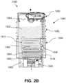
- FIGS. 2D-E depict cross sectional views of examples of the vaporizer cartridge 1320 consistent with implementations of the current subject matter.
- the vaporizer cartridge 1320 may include one or more microfluidic features configured to prevent air and the vaporizable material 1302 from bypassing each other during filling and emptying of the collector 1313. These microfluidic features, which manage the flow of the vaporizable material 1302 into and out of the collector 1313, may minimize leakage of the vaporizable material 1302 as well as the entrapment of air bubbles in the storage chamber 1342 and/or the overflow volume 1344.
- the collector 1313 of thevaporizer cartridge 1320 may include the overflow channel 1104.
- a first end of the overflow channel 1104 may include the air vent 1318 in fluid communication with the airflow passageway 1338 while a second end of the overflow channel 1104 may include the second opening 210b in fluid communication with the storage chamber 1342.
- the vaporizable material 1302 may enter and exit the overflow channel 1104 through the second opening 210b while air may enter and exit the overflow channel 1104 through the air vent 1318.
- air entering through the air vent 1318 may relieve any vacuum that may develop within the reservoir 140 due to the depletion of the vaporizable material 1302.
- FIGS. 2D-E depict examples of the vaporizer cartridge 1320 having a different placement of the air vent 1318 and the second opening 210b.
- the air vent 1318 may be disposed adjacent to the wick housing 1315 and the wicking element 1362 while the second opening 210b is disposed away from the wick housing 1315 and the wicking element 1362, for example, above the air vent 1318.
- the second opening 210b may be disposed adjacent to the wick housing 1315 and the wicking element 1362 while the air vent 1318 may be disposed away from the wick housing and the wicking element 1362, for example, above the second opening 210b.
- proximity between the wicking element 1362 and the second opening 210b, which is in fluid communication with the storage chamber 1342, may minimize the hydrostatic head between the wicking element 1362 and the storage chamber 1342.
- the example of the vaporizer cartridge 1320 shown in FIG. 2E may be more resilient to leakage through the wicking element 1362 because the negative pressure created by the meniscus at the second opening 210b is preserved instead of being diminished by the hydrostatic head between the wicking element 1362 and the storage chamber 1342.
- the overflow channel 1104 may include one or more microfluidic features including, for example, a first microfluidic feature 230a, a second microfluidic feature 230b, and/or the like.
- the first microfluidic feature 230a and/or the second microfluidic feature 230b may be configured to control the flow of air and the vaporizable material 1302 into and out of the reservoir 140.
- the first microfluidic feature 230a and/or the second fluid features 230b may be configured to discourage the flow of the vaporizable material 1302 in one direction the overflow channel 1104 (e.g., away from the storage chamber 1342 and out of the overflow channel 1104) and encourage the flow of the vaporizable material 1302 in a reverse direction (e.g., back into the storage chamber 1342).
- the first microfluidic feature 230a and the second microfluidic feature 230b may be configured to permit airflow to the storage chamber 1342 through the overflow channel 1104 in order to equalize the pressure inside the storage chamber 1342 with ambient pressure.
- the first microfluidic features 230a may be in the shape of a shark fin, for example, in which the distal end of the first microfluidic feature 230a tapers to an edge.
- the pointed or cantilevered edge of the shark fin shape may be rounded although the cantilevered edge may also be tapered to a sharp end.
- microfluidic features may include one or more variations in the shape and/or orientation of the overflow channel 1104 along a length of the overflow channel 1104.
- at least a portion of the overflow channel 1104 may spiral, curve, bend, taper, turn, and/or slope.
- FIG. 2D shows that the second microfluidic feature 230b may be a curvature in the overflow channel 1104 where the overflow channel 1104 running in one direction turns in an opposite direction.
- the vaporizer cartridge 1320 may couple with the vaporizer body 110 of the vaporizer device 100 in a variety of different manners.
- FIGS. 3A-D depict various design alternatives for connectors configured to form a coupling between the vaporizer cartridge 1320 and the vaporizer body 110 of the vaporizer device 100.
- FIGS. 3A-B each depict perspective views of various examples of the connectors while FIGS. 3C-D each depict planar cross-sectional side views of various examples of the connectors.
- one end of the vaporizer cartridge 1320 may include one or more connectors to enable a coupling between the vaporizer cartridge 1320 and the vaporizer body 110 of the vaporizer device 100.
- one end of the vaporizer cartridge 1320 may include one or more mechanical connectors, electrical connectors, and fluid connectors configured to provide an electrical coupling, a mechanical coupling, and/or a fluid coupling between the vaporizer cartridge 1320 and the vaporizer body 110. It should be appreciated that these connectors may be implemented with various configurations.
- FIGS. 3B and 3D depicts another example of the vaporizer cartridge 1320 in which one end of the vaporizer cartridge 1320 includes a female connector 712.
- the female connector 712 may be a receptacle that is configured to receive a corresponding male connector (e.g., a protrusion) on the vaporizer body 110.
- the contacts 1326 may be disposed inside the female connector 712 and may be configured to form an electric coupling as well as a mechanical coupling with corresponding contacts on the male connector on the vaporizer body 110.
- the vaporizer body 110 may include a shell 1220, a sheath 1219, a battery 1212, a printed circuit board assembly (PCBA) 1203, an antenna 1217, a skeleton 1211, a charge badge 1213, a cartridge interface 1218, an endcap 1201, and an LED badge 1215.
- assembly of the vaporizer body 110 includes placing the battery 1212 within the skeleton 1211 at an inferior end of the skeleton 1211 (left-hand side of FIG. 4 ).
- the antenna 1217 may be coupled to an inferior end of the battery 1212.
- the cartridge interface 1218, the PCBA 1203, and the battery 1212 may be mechanically coupled, for example, via one or more coupling means.
- the shell 1220 formed from the first material may include one or more insets formed from the second material that is penetrable to the radio waves from the antenna 1217.
- one or more strategies such as beamforming, may be implemented to maximize the power of the radio waves irradiating from the endcap 1310 and/or those portions of the shell 1220 formed from the second material.
- the shell 1220 may include grounding pads, an endcap datum, an LED interface, one or more air inlets (that are in fluid communication with the airflow slots at the bottom of the wick housing 1315 when the cartridge 1320 is coupled with the vaporizer body 110), and the snap features 1221 where the skeleton 1211 snaps into place when inserted into the shell 1220.
- the endcap 1201 may be disposed at an inferior end of the shell 1220 opposite the sheath 1219.
- the endcap 1201 may be configured to retain the interior components of the vaporizer body 210 within the shell 1220 and may also serve as a vent on the inferior end of the shell 1220.
- the vaporizer 100 may include electrical connection features (e.g., means for completing a circuit) for completing a circuit that includes the controller 104 (e.g., a printed circuit board, a microcontroller, or the like), the power source, and the heating element.
- electrical connection features e.g., means for completing a circuit
- the controller 104 e.g., a printed circuit board, a microcontroller, or the like
- These features may include at least two contacts 124 on a bottom surface of the vaporizer cartridge 1320 (referred to herein as cartridge contacts 124) and at least two contacts 125 disposed near a base of the cartridge receptacle (referred to herein as receptacle contacts 125) of the vaporizer 100 such that the cartridge contacts 124 and the receptacle contacts 125 make electrical connections when the vaporizer cartridge 1320 is inserted into and coupled with the cartridge receptacle 118.
- the circuit completed by these electrical connections can allow delivery of electrical current to the resistive heating element and may further be used for additional functions, such as for example for measuring a resistance of the resistive heating element for use in determining and/or controlling a temperature of the resistive heating element based on a thermal coefficient of resistivity of the resistive heating element, for identifying a cartridge based on one or more electrical characteristics of a resistive heating element or the other circuitry of the vaporizer cartridge, etc.
- the at least two cartridge contacts and the at least two receptacle contacts can be configured to electrically connect in either of at least two orientations.
- one or more circuits necessary for operation of the vaporizer can be completed by insertion of a vaporizer cartridge 1320 in the cartridge receptacle 118 in a first rotational orientation (around an axis along which the end of the vaporizer cartridge having the cartridge is inserted into the cartridge receptacle 118 of the vaporizer body 110) such that a first set of cartridge contacts of the at least two cartridge contacts 124 is electrically connected to a first set of receptacle contacts of the at least two receptacle contacts 125 and a second set of cartridge contacts of the at least two cartridge contacts 124 is electrically connected to a second set of receptacle contacts of the at least two receptacle contacts 125.
- the one or more circuits necessary for operation of the vaporizer can be completed by insertion of a vaporizer cartridge 1320 in the cartridge receptacle 118 in a second rotational orientation such that the first set of cartridge contacts of the at least two cartridge contacts 124 is electrically connected to the second set of receptacle contacts of the at least two receptacle contacts 125 and the second set of cartridge contacts of the at least two cartridge contacts 124 is electrically connected to the first set of receptacle contacts of the at least two receptacle contacts 125.
- This feature of a vaporizer cartridge 1320 being reversibly insertable into a cartridge receptacle 118 of the vaporizer body 110 is described further below.
- the vaporizer body 110 includes one or more detents (e.g., a dimple, protrusion, spring connector, etc.) protruding inwardly from an inner surface the cartridge receptacle 118.
- detents e.g., a dimple, protrusion, spring connector, etc.
- One or more exterior surfaces of the vaporizer cartridge 1320 can include corresponding recesses (not shown in FIG. 1 ) that can fit and/or otherwise snap over such detents when an end of the vaporizer cartridge 1320 inserted into the cartridge receptacle 118 on the vaporizer body 110.
- Such a detent-recess assembly can provide enough support to hold the vaporizer cartridge 1320 in place to ensure good contact between the at least two cartridge contacts 124 and the at least two receptacle contacts 125, while allowing release of the vaporizer cartridge 1320 from the vaporizer body 110 when a user pulls with reasonable force on the vaporizer cartridge 1320 to disengage the vaporizer cartridge 1320 from the cartridge receptacle 118.
- at least two detents may be disposed on an exterior of the sheath 1219.
- the shape of the vaporizer cartridge, or at least a shape of the end of the vaporizer cartridge that is configured for insertion into the cartridge receptacle may have rotational symmetry of at least order two.
- the vaporizer cartridge or at least the insertable end of the vaporizer cartridge may be symmetric upon a rotation of 180° around an axis along which the vaporizer cartridge is inserted into the cartridge receptacle.
- the circuitry of the vaporizer 100 may support identical operation regardless of which symmetrical orientation of the vaporizer cartridge 1320 occurs.
- the first rotational position may be more than or less than 180° from the second rotational position.
- the vaporizer cartridge 1320 or at least an end of the vaporizer cartridge configured 1320 for insertion in the cartridge receptacle may have a non-circular cross section transverse to the axis along which the vaporizer cartridge is inserted into the cartridge receptacle 118.
- the non-circular cross section may be approximately rectangular, approximately elliptical (e.g., have an approximately oval shape), non-rectangular but with two sets of parallel or approximately parallel opposing sides (e.g., having a parallelogram-like shape), or other shapes having rotational symmetry of at least order two.
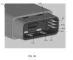
- FIGS. 5A-C depicts various examples of a pod identifier contact 500 consistent with implementations of the current subject matter.
- the pod identifier contact 500 may be part of the cartridge receptacle 118, for example, the cartridge interface 1218.
- the pod identifier contact 500 may be configured to form an electrical coupling between the PCBA 1203 (e.g., the controller 104) and one or more contacts 293 of the identification chip 174.
- the pod identifier contact 500 may be configured to exert a sufficient force against the contact 293 of the identification chip 174 to ensure that the contact between the contacts 293 of the identification chip 174 and the pod identifier contact 500 is adequate for a reading of the identification chip 174.
- the pod identifier contact 500 may be preloaded such that the pod identifier contact 500 applies sufficient spring force against the contacts 293 of the identification chip 174.
- the pod identifier contact 500 may also be disposed at least partially within the sheath 1219 such that a portion 408 of the sheath 1219 may prevent the pod identifier contact 500 from over extending and another portion of the sheath 1219 may prevent the pod identifier contact 500 from contacting the shell 1220 (e.g., and causing a short circuit). Moreover, the dimensions of the pod identifier contact 500 may be configured to resist wear-and-tear from repeated bending of the pod identifier contact 500 as the vaporizer cartridge 1320 is inserted and removed from the vaporizer body 110.
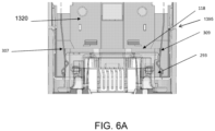
- FIGS. 6A-B depict side cut-out views of the cartridge 1320 disposed within the cartridge receptacle 118 consistent with implementations of the current subject matter.
- the pod identifier contact 307 may be disposed on a first side the cartridge receptacle 118 and may be coupled to the identification chip 174 on the cartridge 1320.
- the pod identifier contact 309 may be located on a second side of the cartridge receptacle 118 (opposite to the first side of the cartridge receptacle 118) and may be coupled to the cartridge 1320.
- FIG. 6A further shows the pod identifier contact 309 as being coupled to a contact 293 of the identification chip 174.
- the retention feature may be configured to align the charger device towards those surfaces of the vaporizer body 110.
- the retention feature may be configured such that the charger device and the vaporizer device 100 are coupled one or more faces (e.g., front face and/or back face) of the vaporizer body 110.
- the retention feature may be configured to secure the vaporizer body 110 to the charger device on any surface (e.g., front face, back face, left side, right side, and/or the like) of the vaporizer body 110.
- FIG. 8F depicts various examples of magnet-to-magnet retention features consistent with implementations of the current subject matter.
- the retention feature 800 at the vaporizer body 110 and the retention feature 815 at the charger device 810 may be implemented using magnets including, for example, magnets having different shapes.
- the retention feature 800 at the vaporizer body 110 may be a rectangular (or circular) magnet while the retention feature 815 at the charger device 810 may be a corresponding rectangular (or circular) magnet.
- the retention feature 800 at the vaporizer body 110 may be a collection of rectangular opposing magnets and the retention feature 815 at the charger device 810 may be a corresponding collection of rectangular opposing magnets.
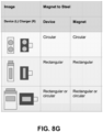
- FIG. 8G depicts various examples of magnet-to-metal retention features consistent with implementations of the current subject matter.
- the retention feature 800 at the vaporizer body 110 may be implemented using magnets while the retention feature 815 at the charger device 810 may be implemented using one or more blocks of ferrous metal (e.g., steel and/or the like).
- the retention feature 800 at the vaporizer body 110 may be implemented using one or more blocks of ferrous metal while the retention feature 815 at the charger device 810 may be implemented using magnets.
- the magnet-to-metal retention features may be implemented in a variety of shapes including, for example, circular, rectangular, and/or the like.
- the vaporizer body 110 may include a number of components including, for example, the shell 1220, the sheath 1219, the battery 1212, the printed circuit board assembly (PCBA) 1203, the antenna 1217, the skeleton 1211, the charge badge 1213, the cartridge interface 1218, the endcap 1201, and the LED badge 1215.
- the assembly of the vaporizer body 110 may include securing the battery 1212, the PCBA 1203, and the antenna 1217 to the skeleton 1211.
- the sheath 1219 may be integral to the shell 1220 such that the sheath 1219 and the shell 1220 may be formed as a solitary unit.
- the sheath 1219 may be coupled to the shell 1220 (e.g., by adhesives, friction fit, welding and/or the like), in which case the cartridge interface 1218 may be further secured to the skeleton 1211 before the assembly including the skeleton 1211, the cartridge interface 1218, the battery 1212, and the PCBA 1203 are inserted into the shell 1220.
- the sheath 1219 and the cartridge interface 1218 may form a first assembly that is secured to the shell 1220 while the skeleton 1211, the PCBA 1203, and the battery 1212 may form a second assembly that is inserted into the shell 1220.
- An open end of the shell 1220 distal to the cartridge receptacle 118 may be sealed with the endcap 1201.
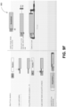
- FIGS. 9A-F depict various examples of processes for assembling the vaporizer body 110 consistent with implementations of the current subject matter.
- FIG. 9A depicts an example of a process 900 for assembling the vaporizer body 110, which may include securing (e.g., by laser welding and/or another technique) the battery 1212 to the PCBA 1203 before installing the cartridge interface 1218 onto the PCBA 1203.
- the antenna 1217 may be attached to the skeleton 1211 at this point or later on.
- a cover for light emitting diodes (LEDs) may be installed onto the cartridge interface 1218 before the sheath 1219 is slid over the cartridge interface 1218.
- LEDs light emitting diodes
- the sheath 1219 may be secured to the skeleton 1211 by laser welding (or another technique).
- the charge badge 1213 may be affixed to one side of the sheath 1219, for example, that is opposite of the light emitting diodes.
- additional soldering and some testing e.g., semi-finished-good (SFG) testing and/or the like
- FSG semi-finished-good
- the antenna 1217 may be installed at this point before the assembly including the skeleton 1211, the sheath 1219, the cartridge interface 1218, the battery 1212, the PCBA 1203, the charge badge 1213, and the LED badge 1215 is inserted into the shell 1220.
- the endcap 1201 may be attached to an inferior end of the shell 1220, for example, by adhesives (or another mechanism) and clamped to cure.
- FIG. 9B depicts another example of a process 910 for assembling the vaporizer body 110 consistent with implementations of the current subject matter.
- the process 910 may include first installing the cartridge interface 1218 onto the PCBA 1203 followed by the cover for the light emitting diodes (LEDs) on the cartridge interface 1218 before the sheath 1219 is slid over the assembly including the cartridge interface 1218 and the PCBA 1203.
- the charge badge 1213 is affixed to one side of the sheath 1219, for example, opposite of the light emitting diodes before soldering is performed and the battery 1212 is attached to the PCBA 1203 (e.g., by laser welding and/or a different technique).
- the resulting assembly including the PCBA 1203, the battery 1212, the cartridge interface 1218 covered with the sheath 1219, and the charge badge 1215 may be coupled with the skeleton 1211.
- This assembly including the skeleton 1211 may be subject to additional welding (e.g., laser welding and/or the like) to secure the skeleton 1211 to the sheath 1219 as well as testing (e.g., semi-finished-good (SFG) testing and/or the like)).
- additional welding e.g., laser welding and/or the like
- testing e.g., semi-finished-good (SFG) testing and/or the like
- the LED badge 1215 may be installed onto the sheath 1219 at this point and the antenna 1217 may be installed before the entire assembly including the skeleton 1211, the cartridge interface 1218 covered with the sheath 1219, the charge badge 1213, the battery 1212, the PCBA 1203, the antenna 1217, the LED badge s1215, and the charge badge 1213 is inserted into the shell 1220.
- the endcap 1201 may be attached to an inferior end of the shell 1220, for example, by adhesives (or another mechanism) and clamped to cure.
- FIG. 9C depicts another example of a process 920 for assembling the vaporizer body 110 consistent with implementations of the current subject matter.
- the battery 1212 may be installed in the skeleton 1211 after the skeleton 1211 has been secured to the assembly including the sheath 1219, the cartridge interface 1218, the PCBA 1203, the LED badge 1213, and the charge badge 1215.
- the process 910 shown in FIG. 9B in which the battery 1212 is first attached to the assembly including the sheath 1219, the cartridge interface 1218, the PCBA 1203, and the charge badge 1213 before being coupled with the skeleton 1211.
- FIG. 9D depicts another example of a process 930 for assembling the vaporizer body 110 consistent with implementations of the current subject matter.
- the process 930 may include installing the cartridge interface 1218 onto the PCBA 1203 before attaching the one or more of the receptacle contacts 125 and the pod identifier contacts 307, for example, by laser soldering and/or the like.
- the battery 1212 may be attached to the assembly including the cartridge interface 1218 and the PCBA 1203 before being coupled with the skeleton 1211 and installing the antenna 1217.
- the resulting assembly including the cartridge interface 1218, the PCBA 1203, the battery 1212, the skeleton 1211, and the antenna 1217 may be inserted into another assembling including the sheath 1219 and the shell 1220.
- the sheath 1219 may be attached to the shell 1220 (e.g., by adhesives, friction fit, welding and/or the like) or the sheath 1219 and the shell 1220 may be formed as a solitary unit.
- the charge badge 1213 and the LED badge 1215 may be installed.
- the endcap 1201 may be attached to an inferior end of the shell 1220, for example, by adhesives (or another mechanism) and clamped to cure.
- FIG. 9E depicts another example of a process 940 for assembling the vaporizer body 110 consistent with implementations of the current subject matter.
- the assembly of the vaporizer body 110 may include installing the cartridge interface 1218 onto the PCBA 1203 to form a first assembly that is then coupled with a second assembly that includes the skeleton 1211 coupled with the antenna 1217.
- the battery 1212 is then disposed within the skeleton 1211 and secured to the PCBA 1203 (e.g., using laser welding and/or another technique).
- the antenna 1217 is then installed before the resulting assembling is subject to testing such as a semi-finished-goods (SFG) testing and/or the like).
- FSG semi-finished-goods
- the assembly including the cartridge interface 1218, the PCBA 1203, the battery 1212, the skeleton 1211, and the antenna 1217 may be inserted into another assembling including the sheath 1219 and the shell 1220.
- the charge badge 1213 and the LED badge 1215 may be installed before (or after) the endcap 1201 is attached to an inferior end of the shell 1220, for example, by adhesives (or another mechanism) and clamped to cure.
- FIG. 9F depicts another example of a process 950 for assembling the vaporizer body 110 consistent with implementations of the current subject matter.
- the cartridge interface 1218 may be attached to the skeleton 1211 to form a first assembly while the battery 1212 and the PCBA 1203 may be coupled to form a second assembly.
- the first assembly including the cartridge interface 1218 and the skeleton 1211 may then be coupled with the second assembly including the battery 1212 and the PCBA 1203, for example, by inserting the second assembly into the skeleton 1211 of the first assembly.
- One or more of the receptacle contacts 125 and the pod identifier contacts 307 may be attached to the cartridge interface 1218, for example, by laser soldering and/or the like.
- the resulting assembly including the cartridge interface 1218, the PCBA 1203, the battery 1212, the skeleton 1211, and the antenna 1217 may be inserted into another assembling including the sheath 1219 and the shell 1220.
- the charge badge 1213 and the LED badge 1215 may be installed before (or after) the endcap 1201 is attached to an inferior end of the shell 1220, for example, by adhesives (or another mechanism) and clamped to cure.
- references to a structure or feature that is disposed "adjacent" another feature may have portions that overlap or underlie the adjacent feature.
- phrases such as "at least one of” or “one or more of” may occur followed by a conjunctive list of elements or features.
- the term “and/or” may also occur in a list of two or more elements or features. Unless otherwise implicitly or explicitly contradicted by the context in which it used, such a phrase is intended to mean any of the listed elements or features individually or any of the recited elements or features in combination with any of the other recited elements or features.
- the phrases “at least one of A and B;” “one or more of A and B;” and “A and/or B” are each intended to mean "A alone, B alone, or A and B together.”
- a similar interpretation is also intended for lists including three or more items.
- phrases “at least one of A, B, and C;” “one or more of A, B, and C;” and “A, B, and/or C” are each intended to mean “A alone, B alone, C alone, A and B together, A and C together, B and C together, or A and B and C together.”
- Use of the term “based on,” above and in the claims is intended to mean, “based at least in part on,” such that an unrecited feature or element is also permissible.
- spatially relative terms such as “forward”, “rearward”, “under”, “below”, “lower”, “over”, “upper” and the like, may be used herein for ease of description to describe one element or feature's relationship to another element(s) or feature(s) as illustrated in the figures. It will be understood that the spatially relative terms are intended to encompass different orientations of the device in use or operation in addition to the orientation depicted in the figures. For example, if a device in the figures is inverted, elements described as “under” or “beneath” other elements or features would then be oriented “over” the other elements or features. Thus, the exemplary term “under” can encompass both an orientation of over and under.
- the device may be otherwise oriented (rotated 90 degrees or at other orientations) and the spatially relative descriptors used herein interpreted accordingly.
- the terms “upwardly”, “downwardly”, “vertical”, “horizontal” and the like are used herein for the purpose of explanation only unless specifically indicated otherwise.
- first and second may be used herein to describe various features/elements (including steps), these features/elements should not be limited by these terms, unless the context indicates otherwise. These terms may be used to distinguish one feature/element from another feature/element. Thus, a first feature/element discussed below could be termed a second feature/element, and similarly, a second feature/element discussed below could be termed a first feature/element without departing from the teachings provided herein.
- a numeric value may have a value that is +/- 0.1% of the stated value (or range of values), +/- 1% of the stated value (or range of values), +/- 2% of the stated value (or range of values), +/- 5% of the stated value (or range of values), +/- 10% of the stated value (or range of values), etc.
- Any numerical values given herein should also be understood to include about or approximately that value, unless the context indicates otherwise. For example, if the value "10" is disclosed, then “about 10" is also disclosed. Any numerical range recited herein is intended to include all sub-ranges subsumed therein.
- One or more aspects or features of the subject matter described herein can be realized in digital electronic circuitry, integrated circuitry, specially designed application specific integrated circuits (ASICs), field programmable gate arrays (FPGAs) computer hardware, firmware, software, and/or combinations thereof.
- ASICs application specific integrated circuits
- FPGAs field programmable gate arrays
- These various aspects or features can include implementation in one or more computer programs that are executable and/or interpretable on a programmable system including at least one programmable processor, which can be special or general purpose, coupled to receive data and instructions from, and to transmit data and instructions to, a storage system, at least one input device, and at least one output device.
- the programmable system or computing system may include clients and servers.
- a client and server are generally remote from each other and typically interact through a communication network. The relationship of client and server arises by virtue of computer programs running on the respective computers and having a client-server relationship to each other.
- machine-readable signal refers to any signal used to provide machine instructions and/or data to a programmable processor.
- the machine-readable medium can store such machine instructions non-transitorily, such as for example as would a non-transient solid-state memory or a magnetic hard drive or any equivalent storage medium.
- the machine-readable medium can alternatively or additionally store such machine instructions in a transient manner, such as for example, as would a processor cache or other random access memory associated with one or more physical processor cores.
- inventive subject matter may be referred to herein individually or collectively by the term "invention" merely for convenience and without intending to voluntarily limit the scope of this application to any single invention or inventive concept, if more than one is, in fact, disclosed.
- inventive concept any arrangement calculated to achieve the same purpose may be substituted for the specific embodiments shown.
- This disclosure is intended to cover any and all adaptations or variations of various embodiments. Combinations of the above embodiments, and other embodiments not specifically described herein, will be apparent to those of skill in the art upon reviewing the above description.
Landscapes
- Engineering & Computer Science (AREA)
- Physics & Mathematics (AREA)
- Electromagnetism (AREA)
- Power Engineering (AREA)
- Human Computer Interaction (AREA)
- Computer Networks & Wireless Communication (AREA)
- Catching Or Destruction (AREA)
- Chemical Vapour Deposition (AREA)
- Disinfection, Sterilisation Or Deodorisation Of Air (AREA)
- Filling Or Discharging Of Gas Storage Vessels (AREA)
Claims (17)
- Dispositif vaporisateur (100), comprenant:une coque (1220);un réceptacle de cartouche (118), formé à partir d'une interface de cartouche (1218) disposée au moins partiellement à l'intérieur d'une gaine (1219), l'interface de cartouche (1218) étant conçue pour fournir une
pluralité de couplages électriques avec une cartouche de vaporisateur (1320) lorsque la cartouche de vaporisateur (1320) est disposée au moins partiellement à l'intérieur du réceptacle de cartouche (118), la pluralité de couplages électriques comprenant un premier couplage électrique avec un élément chauffant (1350) de la cartouche de vaporisateur (1320), et la pluralité de couplages électriques comprenant en outre un deuxième couplage électrique avec une puce d'identification de cartouche (174) de la cartouche de vaporisateur (1320); etun squelette (1211) couplé à l'interface de cartouche (1218), le squelette (1211) étant conçu pour fixer l'interface de cartouche (1218) à l'intérieur de la coque (1220),dans lequel l'interface de cartouche (1218) comprend un ensemble de contacts réceptacles conçus pour former le premier couplage électrique avec un ensemble de contacts chauffants de l'élément chauffant de la cartouche de vaporisateur (1320),dans lequel l'interface de cartouche (1218) comprend en outre un ensemble de contacts d'identification de cartouche conçus pour former le deuxième couplage électrique avec un ensemble correspondant de contacts d'identification de cartouche au niveau de la puce d'identification de cartouche du dispositif vaporisation (100), etcaractérisé en ce que l'ensemble de contacts d'identification de cartouche comprend un premier ensemble de trois contacts électriques disposés sur un côté du réceptacle de cartouche (118) et un deuxième ensemble de trois contacts électriques disposés sur un côté opposé du réceptacle de cartouche (118). - Dispositif vaporisateur (100) selon la revendication 1, comprenant en outre :une batterie (1212) ; etun ensemble de carte de circuit imprimé (1203) comprenant un contrôleur (104) du dispositif vaporisateur (100), l'ensemble de carte de circuit imprimé (1203) étant couplé à la batterie (1212) et à l'interface de cartouche (1218) pour former un premier ensemble, le premier ensemble étant couplé au squelette (1211) pour former un deuxième ensemble qui est disposé à l'intérieur de la coque (1220).
- Dispositif vaporisateur (100) selon la revendication 2, dans lequel le deuxième ensemble comprend en outre une antenne (1217).
- Dispositif vaporisateur (100) selon la revendication 3, dans lequel la coque (1220) est formé à partir d'un premier matériau, dans lequel le dispositif vaporisateur (100) comprend en outre un capuchon d'extrémité (1201) formé à partrir d'un second matériau qui est plus perméable aux ondes radio provenant de l'antenne (1217) que le premier matériau, et dans lequel le capuchon d'extrémité (1201) est conçu pour rendre étanche une extrémité ouverte de la coque (1220) opposée au réceptacle de cartouche (118).
- Dispositif vaporisateur (100) selon la revendication 4, dans lequel la coque (1220) comprend un ou plusieurs inserts formés à partir du deuxième matériau et/ou d'un troisième matériau qui sont plus perméables aux ondes radio provenant de l'antenne (1217) que le premier matériau.
- Dispositif vaporisateur (100) selon l'une quelconque des revendications 1 à 5, dans lequel l'ensemble de contacts de réceptacle comprend deux paires de contacts électriques disposés sur les côtés opposés du réceptacle de cartouche (118).
- Dispositif vaporisateur (100) selon l'une quelconque des revendications 1 à 6, dans lequel l'ensemble de contacts d'identification de cartouche comprend au moins un contact électrique qui est préchargé pour exercer une force contre un contact électrique correspondant au niveau de la puce d'identification de cartouche (174) de la cartouche de vaporisateur (1320).
- Dispositif vaporisateur (100) selon la revendication 7, dans lequel la gaine (1219) est conçue pour empêcher une extension excessive d'au moins un contact électrique, et dans lequel la gaine (1219) est en outre conçue pour empêcher tout contact entre au moins un contact électrique et la coque (1220) du dispositif vaporisateur (100).
- Dispositif vaporisateur (100) selon l'une quelconque des revendications 1 à 8, dans lequel le réceptacle de cartouche(118) est conçue pour recevoir la cartouche de vaporisateur (1320) dans une première orientation rotative et une deuxième orientation rotative, et dans lequel l'interface de cartouche (1218) est conçue pour fournir la pluralité de couplages électriques avec la cartouche de vaporisateur (1320) que la cartouche de vaporisateur (1320) soit insérée dans la première orientation rotative ou dans la deuxième orientation rotative.
- Dispositif vaporisateur (100) selon l'une quelconque des revendications 1 à 9, dans lequel la gaine (1219) et la coque (1220) sont formées comme une unité unique.
- Dispositif vaporisateur (100) selon l'une quelconque des revendications 1 à 10, dans lequel la gaine (1219) est couplée à la coque (1220) par un ou plusieurs éléments parmi un adhésif, un ajustement par friction et/ou une soudure.
- Dispositif vaporisateur (100) selon l'une quelconque des revendications 1 à 11, dans lequel l'interface de cartouche (1218) est en outre conçue pour former, avec la cartouche de vaporisateur (1320), un couplage mécanique conçu pour retenir la cartouche de vaporisateur (1320) à l'intérieur du réceptacle de cartouche (118).
- Dispositif vaporisateur (100) selon l'une quelconque des revendications 1 à 12, comprenant en outre :
un premier élément de retenue (800) configurée pour coupler le dispositif vaporisateur (100) à un dispositif chargeur (810), le premier élément de retenue (800) étant conçues pour former un couplage magnétique avec un deuxième élément de retenue (815) au niveau du dispositif chargeur (810), le couplage magnétique alignant et maintenant le dispositif vaporisateur (100) dans une ou plusieurs positions et/ou orientations par rapport au dispositif chargeur (810). - Dispositif vaporisateur (100) selon la revendication 13, dans lequel le premier élément de retenue (800) et le deuxième élément de retenue (815) comprennent chacun un ou plusieurs aimants.
- Dispositif vaporisateur (100) selon la revendication 13 ou 14, dans lequel l'un des premiers éléments de retenue (800) et deuxième élément de retenue (815) comprend un ou plusieurs aimants, et dans lequel l'autre des premiers éléments de retenue (800) et deuxième élément de retenue (815) comprend un ou plusieurs blocs de métal ferreux.
- Dispositif vaporisateur (100) selon l'une quelconque des revendications 1 à 15, dans lequel le squelette (1211) comprend un ou plusieurs dispositifs d'arrêt pour fixer, à l'intérieur de la coque (1220), le squelette (1211) couplé à l'interface de cartouche (1218).
- Dispositif vaporisateur (100) selon l'une quelconque des revendications 1 à 16, comprenant en outre la cartouche de vaporisateur (1320),dans lequel la cartouche de vaporisateur (1320) comprend en outre un boîtier de mèche (1315)
contenant un élément de mèche (1315), etdans lequel le réceptacle de cartouche (118) est conçu pour recevoir au moins une partie du boîtier de mèche (1315) contenant l'élément de mèche (1362), et le premier couplage électrique étant formé par au moins la mise en contact d'une partie de contact de l'élément chauffant (1350) disposé au moins partiellement à l'extérieur du boîtier de mèche (1315) tandis qu'une partie chauffante de l'élément chauffant (1350) est disposée au moins partiellement à l'intérieur du boîtier de mèche (1315).
Priority Applications (1)
| Application Number | Priority Date | Filing Date | Title |
|---|---|---|---|
| EP25188227.0A EP4635325A3 (fr) | 2019-11-04 | 2020-11-04 | Dispositif vaporisateur |
Applications Claiming Priority (6)
| Application Number | Priority Date | Filing Date | Title |
|---|---|---|---|
| US201962930508P | 2019-11-04 | 2019-11-04 | |
| US201962947496P | 2019-12-12 | 2019-12-12 | |
| US202062981498P | 2020-02-25 | 2020-02-25 | |
| US16/805,672 US11253001B2 (en) | 2019-02-28 | 2020-02-28 | Vaporizer device with vaporizer cartridge |
| US202063108874P | 2020-11-03 | 2020-11-03 | |
| PCT/US2020/058947 WO2021092063A1 (fr) | 2019-11-04 | 2020-11-04 | Dispositif vaporisateur |
Related Child Applications (1)
| Application Number | Title | Priority Date | Filing Date |
|---|---|---|---|
| EP25188227.0A Division EP4635325A3 (fr) | 2019-11-04 | 2020-11-04 | Dispositif vaporisateur |
Publications (3)
| Publication Number | Publication Date |
|---|---|
| EP4054360A1 EP4054360A1 (fr) | 2022-09-14 |
| EP4054360C0 EP4054360C0 (fr) | 2025-07-09 |
| EP4054360B1 true EP4054360B1 (fr) | 2025-07-09 |
Family
ID=73646476
Family Applications (2)
| Application Number | Title | Priority Date | Filing Date |
|---|---|---|---|
| EP20816723.9A Active EP4054360B1 (fr) | 2019-11-04 | 2020-11-04 | Dispositif vaporisateur |
| EP25188227.0A Pending EP4635325A3 (fr) | 2019-11-04 | 2020-11-04 | Dispositif vaporisateur |
Family Applications After (1)
| Application Number | Title | Priority Date | Filing Date |
|---|---|---|---|
| EP25188227.0A Pending EP4635325A3 (fr) | 2019-11-04 | 2020-11-04 | Dispositif vaporisateur |
Country Status (13)
| Country | Link |
|---|---|
| US (1) | US20220256922A1 (fr) |
| EP (2) | EP4054360B1 (fr) |
| JP (1) | JP2022554016A (fr) |
| KR (1) | KR20220093142A (fr) |
| CN (1) | CN114650742A (fr) |
| AU (1) | AU2020377965B2 (fr) |
| CA (1) | CA3159787A1 (fr) |
| ES (1) | ES3042228T3 (fr) |
| GB (2) | GB2606271B (fr) |
| MX (2) | MX2022005147A (fr) |
| PH (1) | PH12022551028A1 (fr) |
| TW (2) | TW202504512A (fr) |
| WO (1) | WO2021092063A1 (fr) |
Families Citing this family (3)
| Publication number | Priority date | Publication date | Assignee | Title |
|---|---|---|---|---|
| WO2021158758A1 (fr) | 2020-02-04 | 2021-08-12 | Juul Labs, Inc. | Dispositif de distribution d'aérosol doté de récipient jetable |
| EP3888477B1 (fr) | 2020-03-30 | 2025-08-06 | Imperial Tobacco Limited | Composant d'administration d'aérosol |
| US12063971B2 (en) | 2021-07-13 | 2024-08-20 | Imperial Tobacco Limited | Aerosol delivery component |
Citations (2)
| Publication number | Priority date | Publication date | Assignee | Title |
|---|---|---|---|---|
| DE102017121664A1 (de) * | 2017-09-19 | 2019-03-21 | Hauni Maschinenbau Gmbh | Komponententeil und Basisteil für einen Inhalator, sowie Verfahren zur Fertigung derselben |
| EP3756481A2 (fr) * | 2019-06-27 | 2020-12-30 | Shenzhen Relx Technology Co., Ltd. | Vaporisateur électronique, corps de dispositif de vaporisateur électronique et dispositif de vaporisateur électronique |
Family Cites Families (19)
| Publication number | Priority date | Publication date | Assignee | Title |
|---|---|---|---|---|
| RU2544839C2 (ru) * | 2010-05-28 | 2015-03-20 | Эппл Инк. | Соединитель с двойной ориентацией с внешними контактами |
| PL4179891T3 (pl) * | 2013-08-06 | 2025-09-01 | Fontem Ventures B.V. | Elektroniczne urządzenie do palenia i proces jego wytwarzania |
| EP3043663A4 (fr) * | 2013-09-13 | 2017-05-10 | Nicodart Inc. | Appareil électronique programmable de vaporisation et système d'arrêt du tabac |
| US9861133B2 (en) * | 2013-12-31 | 2018-01-09 | Shenzhen First Union Technology Co., Ltd. | Electronic cigarette |
| CN107438373A (zh) * | 2015-02-02 | 2017-12-05 | 无畏品牌责任有限公司 | 个人电子蒸发器 |
| US10172388B2 (en) * | 2015-03-10 | 2019-01-08 | Rai Strategic Holdings, Inc. | Aerosol delivery device with microfluidic delivery component |
| US11000069B2 (en) * | 2015-05-15 | 2021-05-11 | Rai Strategic Holdings, Inc. | Aerosol delivery device and methods of formation thereof |
| GB201605101D0 (en) * | 2016-03-24 | 2016-05-11 | Nicoventures Holdings Ltd | Electronic vapour provision system |
| GB201605103D0 (en) * | 2016-03-24 | 2016-05-11 | Nicoventures Holdings Ltd | Vapour provision device |
| PL3487325T3 (pl) * | 2016-07-25 | 2020-12-14 | Philip Morris Products S.A. | Wkład do układu wytwarzania aerozolu z zabezpieczeniem ogrzewacza |
| US10383367B2 (en) * | 2016-07-25 | 2019-08-20 | Fontem Holdings 1 B.V. | Electronic cigarette power supply portion |
| TWI758468B (zh) * | 2017-05-02 | 2022-03-21 | 瑞士商菲利浦莫里斯製品股份有限公司 | 電操作的氣溶膠生成系統、電操作的氣溶膠生成裝置以及充電單元 |
| IL263217B (en) * | 2017-11-24 | 2022-06-01 | Juul Labs Inc | Puff sensing and power circuitry for vaporizer devices |
| WO2019104441A1 (fr) * | 2017-12-02 | 2019-06-06 | Michael Alexander Trzecieski | Dispositif de vaporisateur à cartouche amovible et appareil et procédé de remplissage de cartouche amovible |
| PL3823475T3 (pl) * | 2018-07-19 | 2025-06-02 | Philip Morris Products S.A. | Złącze magnetyczne |
| US20220022537A1 (en) * | 2019-02-07 | 2022-01-27 | Nerudia Limited | Smoking substitute apparatus |
| GB2606847B (en) * | 2019-10-14 | 2023-11-01 | Juul Labs Inc | Vaporizer device microfluidic systems and apparatuses |
| PL4054362T3 (pl) * | 2019-11-06 | 2025-06-09 | Jt International Sa | Papieros elektroniczny z czujnikiem zintegrowanym z jednostką wyświetlającą |
| EP4721607A2 (fr) * | 2020-04-15 | 2026-04-08 | Juul Labs, Inc. | Cartouche pour dispositif vaporisateur |
-
2020
- 2020-11-04 CN CN202080076884.2A patent/CN114650742A/zh active Pending
- 2020-11-04 EP EP20816723.9A patent/EP4054360B1/fr active Active
- 2020-11-04 GB GB2205804.4A patent/GB2606271B/en active Active
- 2020-11-04 GB GB2403305.2A patent/GB2627374B/en active Active
- 2020-11-04 ES ES20816723T patent/ES3042228T3/es active Active
- 2020-11-04 JP JP2022525853A patent/JP2022554016A/ja active Pending
- 2020-11-04 AU AU2020377965A patent/AU2020377965B2/en active Active
- 2020-11-04 CA CA3159787A patent/CA3159787A1/fr active Pending
- 2020-11-04 EP EP25188227.0A patent/EP4635325A3/fr active Pending
- 2020-11-04 TW TW113138769A patent/TW202504512A/zh unknown
- 2020-11-04 TW TW109138485A patent/TWI861271B/zh active
- 2020-11-04 PH PH1/2022/551028A patent/PH12022551028A1/en unknown
- 2020-11-04 MX MX2022005147A patent/MX2022005147A/es unknown
- 2020-11-04 KR KR1020227017444A patent/KR20220093142A/ko active Pending
- 2020-11-04 WO PCT/US2020/058947 patent/WO2021092063A1/fr not_active Ceased
-
2022
- 2022-04-28 MX MX2026000595A patent/MX2026000595A/es unknown
- 2022-05-03 US US17/736,008 patent/US20220256922A1/en active Pending
Patent Citations (3)
| Publication number | Priority date | Publication date | Assignee | Title |
|---|---|---|---|---|
| DE102017121664A1 (de) * | 2017-09-19 | 2019-03-21 | Hauni Maschinenbau Gmbh | Komponententeil und Basisteil für einen Inhalator, sowie Verfahren zur Fertigung derselben |
| US20200229499A1 (en) * | 2017-09-19 | 2020-07-23 | Hauni Maschinenbau Gmbh | Component part and base part for an inhaler, and method for making same |
| EP3756481A2 (fr) * | 2019-06-27 | 2020-12-30 | Shenzhen Relx Technology Co., Ltd. | Vaporisateur électronique, corps de dispositif de vaporisateur électronique et dispositif de vaporisateur électronique |
Also Published As
| Publication number | Publication date |
|---|---|
| TWI861271B (zh) | 2024-11-11 |
| EP4635325A2 (fr) | 2025-10-22 |
| GB202403305D0 (en) | 2024-04-24 |
| MX2026000595A (es) | 2026-03-02 |
| GB2627374A (en) | 2024-08-21 |
| ES3042228T3 (en) | 2025-11-19 |
| GB2606271A (en) | 2022-11-02 |
| US20220256922A1 (en) | 2022-08-18 |
| EP4054360A1 (fr) | 2022-09-14 |
| AU2020377965B2 (en) | 2026-01-29 |
| TW202504512A (zh) | 2025-02-01 |
| TW202126195A (zh) | 2021-07-16 |
| EP4635325A3 (fr) | 2025-11-19 |
| GB2606271B (en) | 2024-05-01 |
| JP2022554016A (ja) | 2022-12-27 |
| PH12022551028A1 (en) | 2023-05-29 |
| EP4054360C0 (fr) | 2025-07-09 |
| MX2022005147A (es) | 2022-06-29 |
| GB2627374B (en) | 2025-02-19 |
| CN114650742A (zh) | 2022-06-21 |
| GB202205804D0 (en) | 2022-06-08 |
| KR20220093142A (ko) | 2022-07-05 |
| AU2020377965A1 (en) | 2022-05-26 |
| WO2021092063A1 (fr) | 2021-05-14 |
| CA3159787A1 (fr) | 2021-05-14 |
Similar Documents
| Publication | Publication Date | Title |
|---|---|---|
| US11253001B2 (en) | Vaporizer device with vaporizer cartridge | |
| US20220256922A1 (en) | Vaporizer device | |
| JP7670615B2 (ja) | 気化器カートリッジを備える気化器デバイス | |
| US12501934B2 (en) | Cartridge for vaporizer device | |
| US20220240576A1 (en) | Encased Battery Cell of a Vaporizer Device | |
| HK40079684A (en) | Vaporizer device | |
| HK40079684B (en) | Vaporizer device | |
| RU2829269C1 (ru) | Испарительное устройство | |
| AU2026202851A1 (en) | Vaporizer device | |
| EP4057852B1 (fr) | Caractéristique de sécurité pour la conception d'élément de batterie | |
| EP4152982B1 (fr) | Coque monobloc pour dispositif vaporisateur | |
| RU2812957C2 (ru) | Испарительное устройство и картридж для него | |
| RU2815677C2 (ru) | Испарительное устройство, способ и система для обратного заряда испарительного устройства | |
| HK40088912A (en) | Cartridge for a vaporizer device | |
| HK40088912B (en) | Cartridge for a vaporizer device | |
| HK40089979B (en) | One-piece shell for vaporizer device | |
| HK40089979A (en) | One-piece shell for vaporizer device |
Legal Events
| Date | Code | Title | Description |
|---|---|---|---|
| STAA | Information on the status of an ep patent application or granted ep patent |
Free format text: STATUS: UNKNOWN |
|
| STAA | Information on the status of an ep patent application or granted ep patent |
Free format text: STATUS: THE INTERNATIONAL PUBLICATION HAS BEEN MADE |
|
| PUAI | Public reference made under article 153(3) epc to a published international application that has entered the european phase |
Free format text: ORIGINAL CODE: 0009012 |
|
| STAA | Information on the status of an ep patent application or granted ep patent |
Free format text: STATUS: REQUEST FOR EXAMINATION WAS MADE |
|
| 17P | Request for examination filed |
Effective date: 20220517 |
|
| AK | Designated contracting states |
Kind code of ref document: A1 Designated state(s): AL AT BE BG CH CY CZ DE DK EE ES FI FR GB GR HR HU IE IS IT LI LT LU LV MC MK MT NL NO PL PT RO RS SE SI SK SM TR |
|
| DAV | Request for validation of the european patent (deleted) | ||
| DAX | Request for extension of the european patent (deleted) | ||
| REG | Reference to a national code |
Ref country code: HK Ref legal event code: DE Ref document number: 40079684 Country of ref document: HK |
|
| GRAP | Despatch of communication of intention to grant a patent |
Free format text: ORIGINAL CODE: EPIDOSNIGR1 |
|
| STAA | Information on the status of an ep patent application or granted ep patent |
Free format text: STATUS: GRANT OF PATENT IS INTENDED |
|
| INTG | Intention to grant announced |
Effective date: 20250203 |
|
| GRAS | Grant fee paid |
Free format text: ORIGINAL CODE: EPIDOSNIGR3 |
|
| GRAA | (expected) grant |
Free format text: ORIGINAL CODE: 0009210 |
|
| STAA | Information on the status of an ep patent application or granted ep patent |
Free format text: STATUS: THE PATENT HAS BEEN GRANTED |
|
| AK | Designated contracting states |
Kind code of ref document: B1 Designated state(s): AL AT BE BG CH CY CZ DE DK EE ES FI FR GB GR HR HU IE IS IT LI LT LU LV MC MK MT NL NO PL PT RO RS SE SI SK SM TR |
|
| RAP3 | Party data changed (applicant data changed or rights of an application transferred) |
Owner name: JUUL LABS, INC. |
|
| REG | Reference to a national code |
Ref country code: GB Ref legal event code: FG4D |
|
| RIN1 | Information on inventor provided before grant (corrected) |
Inventor name: ZHANG, XUEQING Inventor name: ZHANG, XUEHAI Inventor name: YIN, HAO Inventor name: WESTLEY, JAMES P. Inventor name: WESELY, NORBERT Inventor name: VALENTINE, VAL Inventor name: THAWER, ALIM Inventor name: STRATTON, ANDREW J. Inventor name: SHAH, NIHIR B. Inventor name: SCOTT, ZACHARY T. Inventor name: ROSSER, CHRISTOPHER JAMES Inventor name: RIOS, MATTHEW Inventor name: O'MALLEY, CLAIRE Inventor name: NG, NATHAN, N. Inventor name: MONSEES, JAMES Inventor name: MALONE, MATTHEW, J. Inventor name: LOMELI, KEVIN Inventor name: LIANG, HUEI-HUEI Inventor name: LI, YONGCHAO Inventor name: LEON DUQUE, ESTEBAN Inventor name: KING, JASON Inventor name: JOHNSON, ERIC, JOSEPH Inventor name: HOOPAI, ALEXANDER, M. Inventor name: HATTON, NICHOLAS, J. Inventor name: ENTELIS, DYLAN, E. Inventor name: CHRISTENSEN, STEVEN Inventor name: CHEUNG, BRANDON Inventor name: CHANG, TSUEY CHOO LILY Inventor name: BELISLE, CHRISTOPHER, L. Inventor name: BELT, MACKENZIE, PAIGE Inventor name: ATKINS, ARIEL |
|
| REG | Reference to a national code |
Ref country code: CH Ref legal event code: EP |
|
| REG | Reference to a national code |
Ref country code: IE Ref legal event code: FG4D |
|
| REG | Reference to a national code |
Ref country code: DE Ref legal event code: R096 Ref document number: 602020054292 Country of ref document: DE |
|
| U01 | Request for unitary effect filed |
Effective date: 20250807 |
|
| U07 | Unitary effect registered |
Designated state(s): AT BE BG DE DK EE FI FR IT LT LU LV MT NL PT RO SE SI Effective date: 20250820 |
|
| PGFP | Annual fee paid to national office [announced via postgrant information from national office to epo] |
Ref country code: GB Payment date: 20250911 Year of fee payment: 6 |
|
| U20 | Renewal fee for the european patent with unitary effect paid |
Year of fee payment: 6 Effective date: 20251008 |
|
| REG | Reference to a national code |
Ref country code: ES Ref legal event code: FG2A Ref document number: 3042228 Country of ref document: ES Kind code of ref document: T3 Effective date: 20251119 |
|
| REG | Reference to a national code |
Ref country code: CH Ref legal event code: U11 Free format text: ST27 STATUS EVENT CODE: U-0-0-U10-U11 (AS PROVIDED BY THE NATIONAL OFFICE) Effective date: 20251201 |
|
| PG25 | Lapsed in a contracting state [announced via postgrant information from national office to epo] |
Ref country code: IS Free format text: LAPSE BECAUSE OF FAILURE TO SUBMIT A TRANSLATION OF THE DESCRIPTION OR TO PAY THE FEE WITHIN THE PRESCRIBED TIME-LIMIT Effective date: 20251109 |
|
| PG25 | Lapsed in a contracting state [announced via postgrant information from national office to epo] |
Ref country code: NO Free format text: LAPSE BECAUSE OF FAILURE TO SUBMIT A TRANSLATION OF THE DESCRIPTION OR TO PAY THE FEE WITHIN THE PRESCRIBED TIME-LIMIT Effective date: 20251009 |
|
| PG25 | Lapsed in a contracting state [announced via postgrant information from national office to epo] |
Ref country code: HR Free format text: LAPSE BECAUSE OF FAILURE TO SUBMIT A TRANSLATION OF THE DESCRIPTION OR TO PAY THE FEE WITHIN THE PRESCRIBED TIME-LIMIT Effective date: 20250709 |
|
| PG25 | Lapsed in a contracting state [announced via postgrant information from national office to epo] |
Ref country code: GR Free format text: LAPSE BECAUSE OF FAILURE TO SUBMIT A TRANSLATION OF THE DESCRIPTION OR TO PAY THE FEE WITHIN THE PRESCRIBED TIME-LIMIT Effective date: 20251010 |
|
| PGFP | Annual fee paid to national office [announced via postgrant information from national office to epo] |
Ref country code: CH Payment date: 20251201 Year of fee payment: 6 |
|
| PG25 | Lapsed in a contracting state [announced via postgrant information from national office to epo] |
Ref country code: PL Free format text: LAPSE BECAUSE OF FAILURE TO SUBMIT A TRANSLATION OF THE DESCRIPTION OR TO PAY THE FEE WITHIN THE PRESCRIBED TIME-LIMIT Effective date: 20250709 |
|
| PG25 | Lapsed in a contracting state [announced via postgrant information from national office to epo] |
Ref country code: RS Free format text: LAPSE BECAUSE OF FAILURE TO SUBMIT A TRANSLATION OF THE DESCRIPTION OR TO PAY THE FEE WITHIN THE PRESCRIBED TIME-LIMIT Effective date: 20251009 |
|
| PGFP | Annual fee paid to national office [announced via postgrant information from national office to epo] |
Ref country code: ES Payment date: 20251211 Year of fee payment: 6 |
|
| PG25 | Lapsed in a contracting state [announced via postgrant information from national office to epo] |
Ref country code: SM Free format text: LAPSE BECAUSE OF FAILURE TO SUBMIT A TRANSLATION OF THE DESCRIPTION OR TO PAY THE FEE WITHIN THE PRESCRIBED TIME-LIMIT Effective date: 20250709 |
|
| PG25 | Lapsed in a contracting state [announced via postgrant information from national office to epo] |
Ref country code: CZ Free format text: LAPSE BECAUSE OF FAILURE TO SUBMIT A TRANSLATION OF THE DESCRIPTION OR TO PAY THE FEE WITHIN THE PRESCRIBED TIME-LIMIT Effective date: 20250709 |
|
| PG25 | Lapsed in a contracting state [announced via postgrant information from national office to epo] |
Ref country code: SK Free format text: LAPSE BECAUSE OF FAILURE TO SUBMIT A TRANSLATION OF THE DESCRIPTION OR TO PAY THE FEE WITHIN THE PRESCRIBED TIME-LIMIT Effective date: 20250709 |