EP4054375B1 - Fussstützenkomponente für schuhwerk mit mehreren flexiblen vorsprüngen an der bodenseitigen oberfläche - Google Patents
Fussstützenkomponente für schuhwerk mit mehreren flexiblen vorsprüngen an der bodenseitigen oberfläche Download PDFInfo
- Publication number
- EP4054375B1 EP4054375B1 EP20817559.6A EP20817559A EP4054375B1 EP 4054375 B1 EP4054375 B1 EP 4054375B1 EP 20817559 A EP20817559 A EP 20817559A EP 4054375 B1 EP4054375 B1 EP 4054375B1
- Authority
- EP
- European Patent Office
- Prior art keywords
- projections
- projection
- projection field
- sole structure
- sole
- Prior art date
- Legal status (The legal status is an assumption and is not a legal conclusion. Google has not performed a legal analysis and makes no representation as to the accuracy of the status listed.)
- Active
Links
Images






Classifications
-
- A—HUMAN NECESSITIES
- A43—FOOTWEAR
- A43B—CHARACTERISTIC FEATURES OF FOOTWEAR; PARTS OF FOOTWEAR
- A43B13/00—Soles; Sole-and-heel integral units
- A43B13/14—Soles; Sole-and-heel integral units characterised by the constructive form
- A43B13/22—Soles made slip-preventing or wear-resisting, e.g. by impregnation or spreading a wear-resisting layer
- A43B13/24—Soles made slip-preventing or wear-resisting, e.g. by impregnation or spreading a wear-resisting layer by use of insertions
- A43B13/26—Soles made slip-preventing or wear-resisting, e.g. by impregnation or spreading a wear-resisting layer by use of insertions projecting beyond the sole surface
-
- A—HUMAN NECESSITIES
- A43—FOOTWEAR
- A43B—CHARACTERISTIC FEATURES OF FOOTWEAR; PARTS OF FOOTWEAR
- A43B13/00—Soles; Sole-and-heel integral units
- A43B13/14—Soles; Sole-and-heel integral units characterised by the constructive form
- A43B13/22—Soles made slip-preventing or wear-resisting, e.g. by impregnation or spreading a wear-resisting layer
-
- A—HUMAN NECESSITIES
- A43—FOOTWEAR
- A43B—CHARACTERISTIC FEATURES OF FOOTWEAR; PARTS OF FOOTWEAR
- A43B5/00—Footwear for sporting purposes
- A43B5/02—Football boots or shoes, i.e. for soccer, football or rugby
- A43B5/025—Football boots or shoes, i.e. for soccer, football or rugby characterised by an element which improves the contact between the ball and the footwear
-
- A—HUMAN NECESSITIES
- A43—FOOTWEAR
- A43C—FASTENINGS OR ATTACHMENTS OF FOOTWEAR; LACES IN GENERAL
- A43C15/00—Non-skid devices or attachments
- A43C15/16—Studs or cleats for football or like boots
- A43C15/162—Studs or cleats for football or like boots characterised by the shape
Definitions
- the present technology relates to the field of footwear. Aspects of the present technology pertain to foot support components (e.g., sole structures and/or components of sole structures) for articles of footwear that include multiple flexible projections at their ground-facing surfaces.
- foot support components e.g., sole structures and/or components of sole structures
- Conventional articles of athletic footwear include two primary elements, an upper and a sole structure.
- the upper provides a covering for the foot that securely receives and positions the foot with respect to the sole structure.
- the upper may have a configuration that protects the foot and provides ventilation, thereby cooling the foot and removing perspiration.
- the sole structure is secured to a lower surface of the upper and is generally positioned between the foot and any contact surface.
- the sole structure may provide traction and control potentially harmful foot motion, such as over pronation.
- the upper forms a void on the interior of the footwear for receiving the foot.
- the void has the general shape of the foot, and access to the void is provided at an ankle or foot-insertion opening. Accordingly, the upper extends over the instep and toe areas of the foot, along the medial and lateral sides of the foot, and around the heel area of the foot.
- a lacing system often is incorporated into the upper to selectively change the size of the ankle opening and to permit the wearer to modify certain dimensions of the upper, particularly girth, to accommodate feet with varying proportions.
- the upper may include a tongue that extends under the lacing system to enhance the comfort of the footwear (e.g., to modulate pressure applied to the foot by the laces), and the upper also may include a heel counter to limit or control movement of the heel.
- the sole structure generally incorporates multiple layers that are conventionally referred to as an "insole,” a “midsole,” and an “outsole.”
- the insole (which also may constitute a sock liner) is a thin member located within the upper and adjacent the plantar (lower) surface of the foot to enhance footwear comfort, e.g., to wick away moisture.
- the midsole which is traditionally attached to the upper along the upper's entire length, forms the middle layer of the sole structure and serves a variety of purposes that include controlling foot motions and attenuating impact forces.
- the outsole forms the ground-contacting element of footwear and usually is fashioned from a durable, wear-resistant material that includes texturing or other features to improve traction.
- US 2008/209766 A1 and EP 2420152 A2 disclose sole structures.
- Projections may have any desired transverse cross sectional shape, such as round, circular, oval, elliptical, polygonal, rectangular, square, rounded rectangular, cross, star, irregularly shaped, etc.
- a "projection” may have any of the above noted length-to-cross sectional dimension features over a portion of its overall length dimension, such as over at least 50% of the length dimension L, over at least 75% of the length dimension L, over at least 85% of the length dimension L, over at least 90% of the length dimension L, over at least 95% of the length dimension L, over at least 98% of the length dimension L, or even over the entire length dimension L.
- the "projection” may have the noted length-to-cross sectional dimension features over a portion of its overall length dimension measured from its free end.
- field of projections or “projection field” as used herein are interchangeable and mean a region of a sole structure that contains multiple projections of the types described above located within (e.g., dispersed over) its area.
- each projection within the "field” may be located within a distance of 15 mm or less from another projection.
- a “field of projections” or “projection field” may constitute the collection of projections (as defined above) located within 15 mm of at least one other projection.
- the "field of projections" or “projection field” will be formed as a separate part that is engaged with other components of a sole structure.
- the projections may be regularly dispersed over the area of the projection field (e.g., have a substantially constant packing density of "x" projections per square inch) or the projections may have a varying packing density over the area of the projection field.
- a projection field may contain projections of the same or different sizes and/or shapes.
- a "field of projections" or a “projection field” may be integrally formed with another sole part (e.g., an outsole component) or it may be a separate part attached to another sole part or footwear part.
- a “projection field” in accordance with at least some examples of this technology may include any area of a sole structure that includes a projection packing density of at least 4 projections (of the types described above) per square inch (at least 0.62 projections per square centimeter).
- At least some projection fields in accordance with aspects of this technology may include an area of 900 mm 2 to 8000 mm 2 having an average projection packing density within that area (i.e., the total number (N) of projections divided by the total area of the projection field or "projections per unit area”) of at least 4 projections (of the types described above) per square inch (at least 0.62 projections per square centimeter).
- some projection fields in accordance with aspects of this technology may include an area of 900 mm 2 to 8000 mm 2 having an average projection packing density within that area (i.e., projections per unit area) and/or a total number of projections (N) within that area of one or more of: (a) at least 6 projections per square inch (at least 0.93 projections per square centimeter); (b) at least 8 projections per square inch (at least 1.24 projections per square centimeter); (c) 3 to 24 projections per square inch (0.47 to 3.72 projections per square centimeter); (d) 4 to 20 projections per square inch (0.62 to 3.1 projections per square centimeter); (e) 6 to 16 projections per square inch (0.93 to 2.48 projections per square centimeter); (f) at least 20 projections within the projection field area; (g) at least 35 projections within the projection field area; (g) at least 50 projections within the projection field area; (h) from 20 to 250 projections within the projection field area;
- the various different ranges of average projection packing densities and/or total numbers of projections listed above also may be provided within areas of: (a) at least 900 mm 2 ; (b) at least 1200 mm 2 ; (c) at least 1600 mm 2 ; (d) from 900 mm 2 to 5000 mm 2 ; (e) from 1200 mm 2 to 4000 mm 2 ; (f) from 1600 mm 2 to 3600 mm 2 ; (g) from 1200 mm 2 to 6000 mm 2 ; and/or (h) from 1600 mm 2 to 5000 mm 2 .
- a "projection field" may have any one or more and/or any combination of the properties described above.
- Foot support components include multiple flexible projections at their ground-facing surfaces, e.g., located in a field of projections. These projections may assist athletes in sports that include contact and/or control of a ball with the bottom of a foot, such as soccer/global football. As some more specific examples, the projections may assist in one or more of: gripping the ball, transmitting "feel" of the ball through the sole to the wearer's foot (e.g., producing proprioceptive benefits), and/or providing tactile and/or audio feedback confirming contact with the ball.
- Foot support components for articles of footwear include a sole structure having a ground-facing surface and an upper-facing surface.
- the sole structure includes a sole member made from one or more parts and including a base surface, a medial side, and a lateral side.
- a plurality of medial side primary traction elements e.g., soccer cleats
- a plurality of lateral side primary traction elements may be located on the lateral side of the sole member and may extend in a direction away from the base surface.
- a central space may be defined between interior extents (e.g., interior-most surfaces) of the plurality of medial side primary traction elements and the plurality of lateral side primary traction elements, and this central space may be free of primary traction elements (e.g., free of cleats).
- a projection field comprising a plurality of projections is located at least partially in the central space.
- the projection field comprises a plurality of projections that may have a wide variety of features and/or characteristics, as will be described in more detail below.
- the projection field and/or at least some of the projections in the projection field may have a combination of two or more of the parameter values set forth in any one or more of Table 1, Table 2, and/or Table 3 below.
- a single sole structure may include two or more discrete projection fields.
- the projection field may include a plurality of projections (e.g., at least 20 projections) that extend beyond the base surface of the sole structure and have exposed free ends.
- the projection field may define an area of at least 900 mm 2 , e.g., with projections dispersed throughout (e.g., with a constant packing density or a varying packing density), and at least a portion of this projection field includes a projection packing density of at least 4 projections per square inch (0.62 projections per square centimeter).
- a first subset of the plurality of projections may have a length of at least 5 mm, at least 6 mm, or even at least 8 mm, and at least a majority of the plurality of projections in the projection field will readily bend under force applied by weight of a user of the sole structure. In some examples, at least 70%, at least 75%, at least 80%, at least 85%, at least 90%, at least 95%, or even all of the plurality of projections in the projection field will readily bend under force applied by weight of a user of the sole structure (i.e., when contacting the ground).
- the projection field may include a plurality of projections (e.g., at least 20 projections) that extend beyond the base surface of the sole structure and have exposed free ends. At least a majority of the projections of this projection field will readily bend under force applied by weight of a user of the sole structure (and in some examples, at least 70%, at least 75%, at least 80%, at least 85%, at least 90%, at least 95%, or even all of the plurality of projections in the projection field will readily bend under force applied by weight of a user of the sole structure).
- a plurality of projections e.g., at least 20 projections
- a first subset of the plurality of projections will have a sufficient longitudinal length L (at least when fully extended) to have their free ends extend toward the horizontal support surface (and away from the base surface of the sole member) beyond the free end of a closest primary traction element to the respective projection of the first subset.
- Still additional aspects of this technology relate to methods of making footwear components and/or articles of footwear containing them, e.g., of the types and having the structures described above (and described in more detail below).
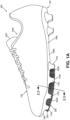
- Figs. 1A-1D provide various views of an article of footwear 100 containing sole structures 104 in accordance with at least some aspects of this technology.
- the term "sole structure” as used herein may include any one or more foot support parts, e.g., forming the entirety and/or a portion of an overall sole for an article of footwear 100.
- Such "foot support parts” may include, for example, any individual part and/or combination of two or more foot support parts described in the examples below and shown in the figures.
- Various features, characteristics, and/or parts of example articles of footwear 100 and sole structures 104 thereof are described in more detail below.
- the article of footwear 100 of Fig. 1A includes an upper 102 and a sole structure 104 engaged with the upper 102.
- the upper 102 and sole structure 104 may be engaged together in any desired manner, including in manners conventionally known and used in the footwear arts (such as by one or more of adhesives or cements, stitching or sewing, mechanical connectors, etc.).
- the upper 102 potentially together with the sole structure 104, define a foot-receiving interior chamber 100I for containing a wearer's foot.
- the bottom of the upper 102 may include a strobel 108 or other component engaged with or integrally formed with another portion of the upper 102, e.g., a lateral side upper component 102L and/or a medial side upper component 102M (see Figs. 2 and 3 ).
- the upper 102 may include other components as well.
- the upper 102 may include a tongue member 102T located across the foot instep area and positioned to moderate the feel of the footwear's closure system on the wearer's foot; a closure system (e.g., including one or more of a lace type closure system, a zippered closure system, a buckle type closure system, elastic stretch elements, etc.); a heel counter; a toe cap; straps; etc.
- the upper 102 may include a "sock-like" upper component, e.g., made from fabric and configured to closely fit the wearer's foot like a conventional sock.
- the upper 102 may be made from any desired material(s) and/or in any desired constructions and/or manners without departing from this technology. As some more specific examples, all or at least a portion of the upper 102 (and optionally a majority, substantially all, or even all of the upper 102) may be formed as a woven textile component, a knitted textile component, another textile component, a natural leather component, a synthetic leather component, a polymeric component (e.g., a TPU, etc.), etc.
- the components for upper 102 may have structures and/or constructions like those used in footwear products commercially available from NIKE, Inc. of Beaverton, OR and/or other manufacturers, including conventional structures and constructions (e.g., for soccer/global football shoes), as are known and used in the art.
- the upper 102 construction may include uppers having foot securing and engaging structures (e.g., "dynamic” and/or “adaptive fit” structures), e.g., of the types described in U.S. Patent Appln. Publn. No. 2013/0104423 .
- uppers and articles of footwear in accordance with this technology may include foot securing and engaging structures of the types used in footwear products commercially available from NIKE, Inc. of Beaverton, Oregon. These types of wrap-around and/or adaptive or dynamic fit structures may at least partially wrap around and securely hold the wearer's foot.
- uppers 102 and articles of footwear 100 in accordance with at least some examples of this technology may include fused layers of upper materials, e.g., uppers of the types that include upper materials bonded by hot melt or other adhesive materials, such as in footwear products commercially available from NIKE, Inc. of Beaverton, Oregon.
- uppers of the types described in U.S. Patent Nos. 7,347,011 and/or 8,429,835 may be used without departing from this technology.
- the sole structure 104 of this example is a cleated sole structure, e.g., well suited for use as part of a soccer/global football shoe.
- the sole structure 104 may be made from one or more parts, in any desired manner, including in manners conventionally known and used in the footwear arts (such as via injection molding techniques, etc.).
- the sole structure 104 includes a sole member 106 (made from one or more parts) having a base surface 106S, a medial side 106M, and a lateral side 106L.
- a plurality of medial side primary traction elements 110M are located on the medial side 106M of the sole member 106 and extend in a direction away from the base surface 106S (e.g., toward and to engage the ground).
- a plurality of lateral side primary traction elements 110L are located on the lateral side 106L of the sole member 106 and extend in a direction away from the base surface 106S (e.g., toward and to engage the ground).
- the primary traction elements 110M and/or 110L may be located at or proximate to an outer perimeter edge of the sole member 106 and/or the overall sole structure 104.
- the term "at or proximate to” as used herein in this context and with respect to these components means that at least some portion of the respective primary traction element 110M and/or 110L is located within 15 mm of an outermost perimeter edge of the sole member 106 and/or the overall sole structure 104 when the sole structure 104 is supported on a horizontal support surface in an unloaded condition.
- primary traction elements 110M and 110L that are located “at or proximate to" the outer perimeter edge of the sole structure 104 and/or sole member 106 may be referred to as "outer edge primary traction elements" (and the projection field 200 (described in more detail below) may be at least partially contained within an area defined by the outer edge primary traction elements).
- the sole structure 104 and/or sole member 106 will include outer edge primary traction elements as the only primary traction elements in the forefoot region and/or in the midfoot region.
- a central space 104S is defined between interior extents of the plurality of medial side primary traction elements 110M and the plurality of lateral side primary traction elements 110L.
- the "interior extents" of the various traction elements may be considered as the interior-most location of the primary traction elements along their lengths (e.g., the locations furthest away from the outer edge of the sole structure 104 and/or sole member 106).
- Dot-dash lines 104E connecting interior extent locations of the primary traction elements 110M and 110L are shown in Fig. 1B .
- a projection field 200 is located at least partially in the central space 104S.
- the projection field 200 has a majority of its area (e.g., at least 50%, and in some examples at least 60%, at least 70%, at least 80%, at least 90%, or even 100% of its area) located in the forefoot region of the sole member 106 and sole structure 104.
- the projection field 200 extends into the midfoot area of the sole member 106 and sole structure 104.
- the projection field 200 comprises a plurality of projections 202 that extend beyond the base surface 104S and have exposed free ends 202E.
- the projection field 200 and the individual projections 202 thereof may have various different properties and combinations of properties, as will be described in more detail below.
- the plurality of projections 202 in the projection field 200 may include at least 20 projections, and in some examples, at least 30, at least 35, at least 40, at least 45, at least 50, from 20 to 250, from 35 to 225, from 50 to 200, from 20 to 100, from 25 to 90, from 30 to 90, or other number (N) of projections.
- the projection field 200 may define any desired area of any desired shape, including an area of at least 900 mm 2 with projections 202 dispersed throughout (and in some example, areas within the ranges of one or more of: at least 1200 mm 2 , at least 1600 mm 2 , at least 2400 mm 2 , from 900 mm 2 to 5000 mm 2 , from 1200 mm 2 to 4000 mm 2 , from 1600 mm 2 to 3600 mm 2 , etc.).
- the projection field 200 area may be defined at least by the area located within lines connecting the outermost extents of the plurality of projections 202 in the projection field 200.
- a first subset of the plurality of projections 202 may have a length L of at least 8 mm (and in some examples, a length L of at least 4 mm, at least 6 mm, at least 10 mm, at least 12 mm, less than 36 mm, less than 30 mm, within a range of 4 mm to 36 mm, within a range of 6 mm to 30 mm, within a range of 8 mm to 28 mm, and/or within a range of 10 mm to 26 mm).
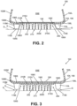
- a first subset of the plurality of projections 202 in the projection field 200 will have their free ends 202E extending toward the horizontal support surface S beyond the free end 104E of a closest primary traction element 110L, 110M to the respective projection 202. See gap G shown in Figs. 2 and 3 (this measurement/determination may be made with the projection 202 extended to its full length (and not bent)).
- the first subset of the plurality of projections 202 having the free end length properties described above may constitute at least 25%, at least 30%, at least 40%, a majority, at least 60%, at least 65%, at least 70%, at least 75%, at least 80%, at least 85%, at least 90%, at least 95%, at least 98%, or even all of the projections 202 in the projection field 200 area.
- the projection field 200 may be incorporated into a footwear 100 structure and/or sole structure 104 in any desired manner without departing from this technology.
- one or more of the projections 202 could be individually engaged with the sole structure 104 (e.g., with sole base member 106) by adhesives or cements, mechanical fasteners, etc.
- one or more of the projections 202 could be integrally formed as part of the sole structure 104 (e.g., part of the sole base member 106) when the sole structure is created (e.g., in a molding step).
- the projection field 200 may be incorporated into a sole structure 104 as one or more separate components 210 that include one or more projections 202.
- Figs. 2 and 3 show examples of such structures.
- the component 210 forming these projection fields 200 includes a projection field base 210B having a first surface 210U (e.g., an upper-facing surface) and a second surface 210G (e.g., a ground-facing surface) opposite the first surface 210U.
- a plurality of projections 202 originate at the second surface 210G and extend from the projection field base 210B in a direction away from the first surface 210U and the second surface 210G.
- the base surface 106S of the sole member 106 includes an interior surface 106I and an exterior surface 106X opposite the interior surface 106I.
- An opening 1060 extends completely through the base surface 106S from the interior surface 106I to the exterior surface 106X. The edge of the opening 1060 also is shown in Figs. 1B-1D .
- the second surface 210G (the ground-facing surface) of the projection field base 210B is engaged with the interior surface 106I of the base surface 106S, e.g., at least around a portion of the outer perimeter edge(s) of the projection field base 210B.
- the projection field base 21 is engaged with the base surface 106S of the interior surface 106I by one or more of adhesives or cements, mechanical connectors, fusing technology, etc.
- the plurality of projections 202 of the projection field 200 extend outward and through the opening 1060.
- the structure of Fig. 2 (e.g., with at least a portion of a projection field component 210 mounted on and to the interior surface 106I of a sole member 106) is advantageous in this technology because a substantial portion of the relatively stiff sole member 106 is removed at opening 1060.
- the first surface 210U of the projection field 200 component 210 may be directly engaged with a bottom of the upper 102, e.g., with a strobel component 108 or other bottom surface of the upper 102.
- the first surface 210U of the projection field base 210B may be flexible (e.g., to conform to the shape of a wearer's foot), planar, and/or smoothly contoured (e.g., suitable for engaging a wearer's foot through the bottom 108 of the upper 102).
- this arrangement can help transmit forces incident on the projection field component 210 and the projections 202 (e.g., from the foot engaging a soccer ball) to the wearer's foot located in the interior chamber 100I of the footwear structure 100. This force transmission helps the wearer "feel" the ball beneath his/her foot, assists the wearer in knowing where the ball is located and what is it doing (with less need to view the ball visually), and helps the wearer better control the ball (with less need to view the ball visually).
- the opening 1060 through which the projection field component 210 is exposed may have a size (area) of at least 900 mm 2 (and in some example, an area within the ranges of one or more of: at least 1200 mm 2 , at least 1600 mm 2 , at least 2500 mm 2 , from 900 mm 2 to 5000 mm 2 , from 1200 mm 2 to 4000 mm 2 , from 1600 mm 2 to 3600 mm 2 , etc.).
- Fig. 3 illustrates an additional or alternative arrangement of a projection field component 210 on a sole structure 104 and/or sole member 106 not in accordance with the claimed invention.
- the first surface 210U (the upper-facing surface) of the projection field base 210B is engaged with the exterior surface 106X of the base surface 106S of the sole member 106.
- the illustrated example of Fig. 3 does not include an opening 1060 as shown in the example of Fig. 2 , such an opening could be provided, e.g., beneath at least some portion of the overall area where the projection field component 210 is engaged with the sole member 106.
- the projection field component 210 may be engaged with exterior surface 106X of the base surface 106S and/or other part of the sole member 106/sole structure 104 in any desired manner, including by one or more of adhesives or cements, mechanical connectors, fusing technology, etc. Because of the sole member 106 base surface 106S located between the projection field component 210 and the interior chamber 100I of the footwear structure 100 in this example (over at least some portion of their interface), this structure may provide somewhat less of the "feel" characteristics described above for the example of Fig. 2 (with the opening 1060).
- the base surface 106B may be made thin and/or flexible at least in the area above the projection field component 210 (e.g., less than 4 mm thick, or even less than 2 mm thick) to permit some level of force transmission (e.g., from ball contact) through the base surface 106B.
- the projection field 200 is located primarily in the forefoot region of the sole structure 104 and/or the sole member 106.
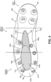
- Fig. 4 shows an article of footwear 400 having a sole structure 404 in which the projection field 200 extends continuously from the forefoot region at least into and through much of the midfoot region of the sole structure 404 and/or sole member 406.
- Any other desired arrangement or proportion of the sole member 406 may include a projection field 200 without departing from this technology, including one or more of the forefoot region, the midfoot region, and/or the heel region.
- a single sole structure 404 and/or sole member 406 may include two or more discrete projection fields 200 located in any individual region and/or combination of regions in the footwear 400, sole structure 404, and/or sole member 406 construction. Wherever located, the sole member 406 and the projection field 200 may have either of the structures and/or engagement arrangements shown in Figs. 2 and/or 3.
- the example projection field 200 of the sole structure 404 and sole member 406 shown in Fig. 4 includes: (a) a first portion 210F located primarily in a forefoot region of the sole structure 404 and sole member 406 (and extending into the midfoot region), and (b) a second portion 210M located primarily or fully in a midfoot region of the sole structure 404 and sole member 406.
- the projection field 200 extends continuously from the forefoot region to the midfoot region of the sole structure.
- the projection field 200 and the sole member 406 may be engaged together by either of the individual structures and/or engagement arrangements shown in Fig. 2 .
- the sole structure 404 of Fig. 4 (as well as other sole structures in accordance with aspects of this technology) may include features of both Fig. 2 in a single sole structure 404/sole member 406.
- the base surface 106S of the sole member 406 includes an interior surface 106I and an exterior surface 106X opposite the interior surface 106I, as described above in conjunction with Figs. 2 .
- An opening 1060 as described above in conjunction with Fig.
- the opening 1060 may be provided beneath the first portion 210F of the projection field 200 in the example of Fig. 4 ).
- the second surface 210G of the projection field base 210B is engaged with the interior surface 106I of the base surface 106S (e.g., around the perimeter of the projection field base 210B and the perimeter of the opening 1060) and the plurality of projections 202 extend through the opening 1060 as described in conjunction with Fig. 2 .
- the outer perimeter of the opening 1060 is shown as element 106P in Fig. 4 .
- the projection field base 210 extends outside the sole member 406 at a second portion of the projection field (e.g., portion 210M).
- the first surface 210U of the projection field base 210B is engaged with the exterior surface 106X of the base surface 106S of the sole member 406, as described in conjunction with Fig. 3 .
- the different hatching in Fig. 4 illustrates: (a) the region with the opening 1060 underlying the projection field component 210 (in region 210F in this example) and (b) the region without an underlying opening 1060 (in region 210M in this example).
- Projection 202 length L also may vary over the area of a projection field 200. As some more specific examples, projection length L may vary over a medial side-to-lateral side direction of a sole structure 104. As one example, the projection length L may get longer or extend further downward in directions toward the center of the projection field (in the medial side-to-lateral side direction) so that the longest and/or furthest extending projections 202 are located in a central area of the projection field 200 and/or sole structure 104.
- the projection length L may get shorter or extend less downward in directions toward the center of the projection field (in the medial side-to-lateral side direction) so that the longest and/or furthest extending projections 202 are located at the outer edges of the projection field 200 and/or sole structure 104.
- the projection lengths L may get shorter or extend downward a shorter distance (e.g., progressively shorter) moving toward the rear of the sole structure 104 (e.g., so that the projections 202 in the forefoot region 210F are somewhat longer or project further downward than the projections 202 in the midfoot region 210M).
- Other variations in projection length L over the course of a projection field 200 and/or sole structure 104 are possible without departing from this technology.
- the individual projections 202 may be formed of a material and structured so that they will readily bend, e.g., under force applied thereto by a wearer's foot and contact with a ground surface and/or under force applied thereto by contact with a ball.
- the individual projections also may be made from a resilient material, e.g., so that they tend to spring back toward or to their original shape after the force(s) is/are sufficiently relaxed. Examples of such materials for the individual projections 202 (as well as the entire projection field 200) include thermoplastic polyurethane materials or other plastic materials.
- force from ball contact with the projections 202 may be transmitted to a wearer's foot (e.g., through the opening 1060 in the sole member 106, 406 and/or, in some examples, even through the base surface 106B of the sole member 106, 406).
- This force transmission may help the wearer "feel" the ball beneath his/her feet, may assist the wearer in knowing where the ball is located and what is it doing (with a lesser need for the player to look down at the ball), and may help the wearer better control the ball (e.g., by better knowing the ball position and what the ball is doing).
- the hardness of the projection material may impact the amount of force transmitted to the wearer's foot (e.g., with harder projections 202 bending less readily and thus potentially transmitting more force to the wearer's foot).
- interaction of the ball with the projections 202 in the projection field 200 may produce an audible scraping or rustling sound as the projections 202 move with respect to the ball surface.
- This audible response also can provide user feedback, e.g., to help the wearer better understand ball position and what the ball is doing underfoot, to control ball possession, etc.
- Various features of the projections 202 and projection field 200 may enable control over the audible response, such as the number/packing density of the projections 202, the hardness/stiffness of the projections, etc.
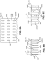
- Figs. 5A through 8C illustrate various views of example projections 202 and portions of projection fields 200 that may be used in accordance with at least some examples of this technology.
- Figs. 5A and 5B provide a partial bottom view and a partial side view, respectively, of an example projection field 200
- Fig. 5C provides an enlarged view of an individual projection 202.
- the projection field 200 may include rows of projections 202 having a longitudinal length L and a transverse cross-sectional diameter or dimension.
- Fig. 5C shows that an individual projection 202 may originate at or extend from the projection field base 210B and extend to a free end 202E.
- the longitudinal length L extends between the projection origination point (e.g., at projection field base 210B) and the free end 202E. To measure this longitudinal length L, it may be necessary to extend the projection 202 to its full length (e.g., if the projection 202 has a curved or bent shape).
- At least some of the individual projections 202 (and optionally a majority, at least 60%, at least 70%, at least 80%, at least 90%, at least 95%, or even all of the individual projections 202) of the projection field 200 may have: (a) a top diameter DT (where the projection 202 extends from the projection field base 210B), (b) a bottom diameter DB (at the free end 202E), and (c) a longitudinal length L extending from the top to the free end 202E.
- One or more of the projections 202 in the projection field 200 may include an angle ⁇ formed from the second surface 210G (ground-facing surface) of the projection field base 210B to the sidewall 202W of the projection 202 over at least a portion of the longitudinal length L, e.g., in a range of 90 degrees to 140 degrees.
- the projection 202 may taper to its smallest diameter and/or transverse area at the free end 202E.
- These angular and taper features may be present, for example, over a majority, at least 60%, at least 70%, at least 80%, at least 90%, at least 95%, or even all of the longitudinal length L of an individual projection 202 (e.g., measured upward from the free end 202E).
- the projection sidewall 202W may extend at an angle of from 0 degrees to 30 degrees with respect to the central axial direction A of the projection 202 over at least a portion of the longitudinal length L.
- this angular feature may be present, for example, over a majority, at least 60%, at least 70%, at least 80%, at least 90%, at least 95%, or even all of the longitudinal length L of an individual projection 202 (e.g., measured upward from the free end 202E).
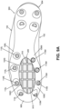
- Figs. 6A and 6B provide a partial bottom view and a partial side view, respectively, of an example projection field 200
- Fig. 6C provides an enlarged view of an individual projection 202.
- the example of Figs. 6A-6C has a wider base (DT) and a greater taper angle ⁇ as compared to the example of Figs. 5A-5C .
- the projection field 200 may include rows of projections 202 having a longitudinal length L and a transverse cross-sectional diameter or dimension.
- Fig. 6C shows that an individual projection 202 may originate at or extend from the projection field base 210B and extend to a free end 202E.
- the longitudinal length L extends between the projection origination point (e.g., at projection field base 210B) and the free end 202E. To measure this longitudinal length L, it may be necessary to extend the projection 202 to its full length (e.g., if the projection 202 has a curved or bent shape).
- At least some of the individual projections 202 (and optionally a majority, at least 60%, at least 70%, at least 80%, at least 90%, at least 95%, or even all of the individual projections 202) of the projection field 200 may have: (a) a top diameter DT (where the projection 202 extends from the projection field base 210B), (b) a bottom diameter DB (at the free end 202E), and (c) a longitudinal length L extending from the top to the free end 202E.
- One or more of the projections 202 in the projection field 200 may include an angle ⁇ formed from the second surface 210G (ground-facing surface) of the projection field base 210B to the sidewall 202W of the projection 202 over at least a portion of the longitudinal length L, e.g., in a range of 90 degrees to 140 degrees.
- the projection 202 may taper to its smallest diameter and/or transverse area at free end 202E.
- These angular and taper features may be present, for example, over a majority, at least 60%, at least 70%, at least 80%, at least 90%, at least 95%, or even all of the longitudinal length L of an individual projection 202 (e.g., measured upward from the free end 202E).
- the projection sidewall 202W may extend at an angle of from 0 degrees to 30 degrees with respect to the central axial direction A of the projection 202 over at least a portion of the longitudinal length L.
- this angular feature may be present, for example, over a majority, at least 60%, at least 70%, at least 80%, at least 90%, at least 95%, or even all of the longitudinal length L of an individual projection 202 (e.g., measured upward from the free end 202E).
- Figs. 5A to 6C show projections 202 having circular transverse cross sections.
- the term "diameter" in the discussion and equations above (and the discussion below) may be interpreted as the widest or largest transverse cross sectional dimension of the projection 202.
- the same values and/or ranges of values described above for the examples of Figs. 5A to 6C apply to the widest or largest transverse cross sectional dimension of such other rounded but non-circular shape projections 202.
- 5A-6C may have one or more of the following properties: a largest transverse cross sectional diameter/dimension of 10 mm or less; a largest transverse cross sectional diameter/dimension of 5 mm or less; a largest transverse cross sectional diameter/dimension of 3 mm or less; and/or a tapered shape along the length dimension L to a smallest transverse cross sectional diameter/dimension at the free ends 202E of the respective projection 202. Any of the above properties also may apply to at least 25 projections 202, at least 30 projections 202, at least 35 projections 202, at least 40 projections 202, or even at least 50 projections 202 in a projection field 200.
- At least some of the individual projections 202 (and optionally at least 25%, at least 40%, at least 50%, at least 60%, at least 70%, at least 80%, at least 90%, at least 95%, or even all of the individual projections 202) of the projection field 200 may have one or more and/or any combination of the properties and/or property values set forth in Table 1 below: TABLE 1: Parameter Value A Value B Value C Top Diameter/Dimension (DT) Less than 12 mm Less than 10 mm Less than 8 mm Bottom Diameter/Dimension (DB) Less than 6 mm Less than 4 mm Less than 2 mm Length Dimension (L) At least 4 mm At least 6 mm At least 8 mm Length Dimension (L) At least 10 mm At least 15 mm At least 20 mm Top Diameter/Dimension (DT) 1 mm to 12 mm
- the angular values need not be included over the entire longitudinal length L of the projection 202, but may be present, for example, over at least 50% of the projection's longitudinal length, optionally at the bottom half of the projection's longitudinal length L.
- Projections 202 may have transverse cross sectional shapes other than rounded or circular.
- Figs. 7A through 8C show projections 202 having polygonal shapes (e.g., four sided parallelograms, optionally generally rectangular, square, etc.).
- Fig. 7A provides a partial bottom view of an example projection field 200
- Fig. 7B provides a narrow side (polygon narrow side) view of the projection field 200
- Fig. 7C provides a wide side (polygon wide side) view of the projection field 200.
- the projection field 200 may include rows of projections 202 having a longitudinal length L and a generally rectangular transverse cross-sectional shape.
- FIGS. 7B and 7C show that an individual projection 202 may originate at or extend from the projection field base 210B and extend to a free end 202E.
- the longitudinal length L extends between the projection origination point (e.g., at projection field base 210B) and the free end 202E. To measure this longitudinal length L, it may be necessary to extend the projection 202 to its full length (e.g., if the projection 202 has a curved or bent shape).
- At least some of the individual projections 202 (and optionally a majority, at least 60%, at least 70%, at least 80%, at least 90%, at least 95%, or even all of the individual projections 202) of the projection field 200 may have: (a) a narrow side width dimension at the top WNT (where the projection 202 extends from the projection field base 210B), (b) a narrow side bottom dimension WNB (at the free end 202E), and (c) a longitudinal length L extending from the top to the free end 202E.
- one or more of the projections 202 in the projection field 200 may include an angle ⁇ formed from the second surface 210G (ground-facing surface) of the projection field base 210B to the narrow sidewall 202NW of the projection 202 over at least a portion of the longitudinal length L, e.g., in a range of 90 degrees to 140 degrees.
- the projection 202 may taper to its smallest transverse area at free end 202E.
- These angular and taper features may be present, for example, over a majority, at least 60%, at least 70%, at least 80%, at least 90%, at least 95%, or even all of the longitudinal length L of an individual projection 202 (e.g., measured upward from the free end 202E).
- the projection narrow sidewall 202NW may extend at an angle of from 0 degrees to 30 degrees with respect to the central axial direction A of the projection 202 over at least a portion of the longitudinal length L.
- this angular feature may be present, for example, over a majority, at least 60%, at least 70%, at least 80%, at least 90%, at least 95%, or even all of the longitudinal length L of an individual projection 202 (e.g., measured upward from the free end 202E).
- At least some of the individual projections 202 (and optionally a majority, at least 60%, at least 70%, at least 80%, at least 90%, at least 95%, or even all of the individual projections 202) of the projection field 200 may have: (a) a wide side width dimension at the top WWT (where the projection 202 extends from the projection field base 210B), (b) a wide side bottom dimension WWB (at the free end 202E), and (c) a longitudinal length L extending from the top to the free end 202E.
- a wide side width dimension at the top WWT where the projection 202 extends from the projection field base 210B
- WWB wide side bottom dimension
- L longitudinal length L extending from the top to the free end 202E.
- one or more of the projections 202 in the projection field 200 may include an angle ⁇ formed from the second surface 210G (ground-facing surface) of the projection field base 210B to the wide sidewall 202WW of the projection 202 over at least a portion of the longitudinal length L, e.g., in a range of 90 degrees to 140 degrees.
- the projection 202 may taper to its smallest transverse area at free end 202E.
- These angular and taper features may be present, for example, over a majority, at least 60%, at least 70%, at least 80%, at least 90%, at least 95%, or even all of the longitudinal length L of an individual projection 202 (e.g., measured upward from the free end 202E).
- the projection wide sidewall 202WW may extend at an angle of from 0 degrees to 30 degrees with respect to the central axial direction A of the projection 202 over at least a portion of the longitudinal length L.
- this angular feature may be present, for example, over a majority, at least 60%, at least 70%, at least 80%, at least 90%, at least 95%, or even all of the longitudinal length L of an individual projection 202 (e.g., measured upward from the free end 202E).
- Fig. 8A provides a partial bottom view of an example projection field 200
- Fig. 8B provides a narrow side (polygon narrow side) view of the projection field 200
- Fig. 8C provides a wide side (polygon wide side) view of the projection field 200.
- the example of Figs. 7A-7C has a greater amount of taper or greater taper angle from base 201B (e.g., more "doorstop” or "wedge” shaped) as compared to the example of Figs. 8A-8C (which is more "fin” shaped).
- the projection field 200 of this example may include rows of projections 202 having a longitudinal length L and a generally rectangular transverse cross-sectional shape.
- Figs. 8B and 8C show that an individual projection 202 may originate at or extend from the projection field base 210B and extend to a free end 202E.
- the longitudinal length L extends between the projection origination point (e.g., at projection field base 210B) and the free end 202E. To measure this longitudinal length L, it may be necessary to extend the projection 202 to its full length (e.g., if the projection 202 has a curved or bent shape).
- At least some of the individual projections 202 (and optionally a majority, at least 60%, at least 70%, at least 80%, at least 90%, at least 95%, or even all of the individual projections 202) of the projection field 200 may have: (a) a narrow side width dimension at the top WNT (where the projection 202 extends from the projection field base 210B), (b) a narrow side bottom dimension WNB (at the free end 202E), and (c) a longitudinal length L extending from the top to the free end 202E.
- a narrow side width dimension at the top WNT where the projection 202 extends from the projection field base 210B
- WNB at the free end 202E
- a longitudinal length L extending from the top to the free end 202E.
- one or more of the projections 202 in the projection field 200 may include an angle ⁇ formed from the second surface 210G (ground-facing surface) of the projection field base 210B to the narrow sidewall 202NW of the projection 202 over at least a portion of the longitudinal length L, e.g., in a range of 90 degrees to 140 degrees.
- the projection 202 may taper to its smallest transverse cross-sectional area at free end 202E.
- These angular and taper features may be present, for example, over a majority, at least 60%, at least 70%, at least 80%, at least 90%, at least 95%, or even all of the longitudinal length L of an individual projection 202 (e.g., measured upward from the free end 202E).
- the projection narrow sidewall 202NW may extend at an angle of from 0 degrees to 30 degrees with respect to the central axial direction A of the projection 202 over at least a portion of the longitudinal length L.
- this angular feature may be present, for example, over a majority, at least 60%, at least 70%, at least 80%, at least 90%, at least 95%, or even all of the longitudinal length L of an individual projection 202 (e.g., measured upward from the free end 202E).
- one or more of the projections 202 in the projection field 200 may include an angle ⁇ formed from the second surface 210G (ground-facing surface) of the projection field base 210B to the wide sidewall 202WW of the projection 202 over at least a portion of the longitudinal length L, e.g., in a range of 90 degrees to 140 degrees.
- the projection 202 may taper to its smallest transverse cross-sectional area at its free end 202E.
- These angular and taper features may be present, for example, over a majority, at least 60%, at least 70%, at least 80%, at least 90%, at least 95%, or even all of the longitudinal length L of an individual projection 202 (e.g., measured upward from the free end 202E).
- the projection wide sidewall 202WW may extend at an angle of from 0 degrees to 30 degrees with respect to the central axial direction A of the projection 202 over at least a portion of the longitudinal length L.
- this angular feature may be present, for example, over a majority, at least 60%, at least 70%, at least 80%, at least 90%, at least 95%, or even all of the longitudinal length L of an individual projection 202 (e.g., measured upward from the free end 202E).
- Figs. 7A to 8C show projections 202 having rectangular or non-square parallelogram transverse cross sections.
- the term "wide side” in the discussion and equations above (and the discussion below) may be interpreted as the widest or largest transverse cross sectional dimension of the projection 202
- the term “narrow side” in the discussion and equations above (and the discussion below) may be interpreted as the narrowest or smallest transverse cross sectional dimension of the projection 202.
- a polygonal transverse cross sectional shape with a largest polygon side dimension of 10 mm or less may have one or more of the following properties: a polygonal transverse cross sectional shape with a largest polygon side dimension of 10 mm or less; a rectangular or parallelogram transverse cross sectional shape with a wide side dimension of 10 mm or less and a narrow side dimension of 6 mm or less; a rectangular or parallelogram transverse cross sectional shape with a wide side dimension of 8 mm or less and a narrow side dimension of 5 mm or less; a tapered shape along the length dimension L to a smallest transverse cross sectional size and/or area at the free ends 202E of the respective projection 202. Any of the above properties also may apply to at least 25 projections 202, at least 30 projections 202, at least 35 projections 202, at least 40 projections 202, or even at least 50 projections 202 in a projection field 200.
- At least some of the individual projections 202 (and optionally at least 25%, at least 40%, at least 50%, at least 60%, at least 70%, at least 80%, at least 90%, at least 95%, or even all of the individual projections 202) of the projection field 200 may have one or more and/or any combination of the properties and/or property values set forth in Table 2 below: TABLE 2: Parameter Value A Value B Value C Wide Side Top Dimension (WWT) Less than 15 mm Less than 12 mm Less than 10 mm Wide Side Bottom Dimension (WWB) Less than 12 mm Less than 10 mm Less than 8 mm Length Dimension (L) At least 10 mm At least 15 mm At least 20 mm Wide Side Top Dimension (WWT) 3 mm to 15 mm 4 mm to 12 mm 5 mm to 10 mm Wide Side Bottom Dimension
- the angular values need not be included over the entire longitudinal length L of the projection 202, but may be present, for example, over at least 50% of the projection's longitudinal length, optionally at the bottom half of the projection's longitudinal length L.
- one or more of the primary traction elements 110M and 110L will have a transverse cross sectional diameter (D1), largest transverse cross sectional dimension (D2), and/or transverse cross sectional area (A1): (a) at a location halfway down their longitudinal length and/or (b) at a location 5 mm upward from their free ends 110E that is at least 3 times greater than the transverse cross sectional diameter (D3), largest transverse cross sectional dimension (D4), and/or transverse cross sectional area (A2) of a majority of the projections 202 in the projection field 200 (and in some examples, at least 75%, at least 85%, at least 90%, at least 95%, or even all of the projections 202 in the projection field 200): (a) at locations halfway down their respective longitudinal length and/or at a location 5 mm upward from their free ends 202E.
- D1 transverse cross sectional diameter
- D2 largest transverse cross sectional dimension
- A1 transverse cross sectional area
- At least one of the primary traction elements 110M, 110L may have one or more of the following features with respect to at least a majority (and in some examples, at least 75%, at least 85%, at least 90%, at least 95%, or even all of the projections 202 in the projection field 200): D 1 ⁇ 3 ⁇ D 3 D 2 ⁇ 3 ⁇ D 4 A 1 ⁇ 3 ⁇ A 2 D 1 ⁇ 4 ⁇ D 3 D 2 ⁇ 4 ⁇ D 4 A 1 ⁇ 4 ⁇ A 2 D 1 ⁇ 6 ⁇ D 3 D 2 ⁇ 6 ⁇ D 4 A 1 ⁇ 6 ⁇ A 2 D 1 ⁇ 8 ⁇ D 3 D 2 ⁇ 8 ⁇ D 4 A 1 ⁇ 8 ⁇ A 2 D 1 ⁇ 10 ⁇ D 3 D 2 ⁇ 10 ⁇ D 4 A 1 ⁇ 10 ⁇ D 3 D 2 ⁇ 10 ⁇ D 4 A 1 ⁇ 10 ⁇ D 1 ⁇ 10 ⁇ D 3 D 2 ⁇ 10 ⁇ D 4 A 1 ⁇ 10 ⁇ D 1 ⁇ 10
- An individual or discrete projection field 200 need not have all projections 202 contained therein of substantially the same size and/or shape. Rather, if desired, different projection 202 sizes (e.g., diameters, dimensions, areas, lengths, taper angles, etc.) and/or shapes (e.g., rounded cross section, rectangular cross section, circular cross section, and/or other cross sections) may be provided within a single projection field 200 without departing from this technology.
- different projection 202 sizes e.g., diameters, dimensions, areas, lengths, taper angles, etc.
- shapes e.g., rounded cross section, rectangular cross section, circular cross section, and/or other cross sections
- the longitudinal lengths L of the projections 202 may vary such that the free ends 202E of the projections 202 provide a contoured arrangement (e.g., with shorter projections 202 located toward a central area of the projection field 200, with shorter projections 202 located toward an outer perimeter of the projection field 200, etc.).
- Projections 202 and projection fields 200 in accordance with at least some examples of this technology may have one or more and/or any combination of the properties and/or property values set forth in Table 3 below: TABLE 3: Parameter Value A Value B Value C Projection Field 200 Area At least 900 mm 2 At least 1200 mm 2 At least 1600 mm 2 Projection Field 200 Area 900 mm 2 to 5000 mm 2 1200 mm 2 to 4000 mm 2 1600 mm 2 to 3600 mm 2 Projection Field 200 Area 900 mm 2 to 8000 mm 2 1200 mm 2 to 6000 mm 2 1600 mm 2 to 5000 mm 2 Projection 202 Packing Density in the Projection Field 200 At least 4 projections per square inch (at least 0.62 projections per square centimeter) At least 6 projections per square inch (at least 0.93 projections per square centimeter) At least 8 projections per square inch (at least 1.24 projections per square centimeter) Projection 202 Packing Density in the Projection Field 200 3 to 24 projections per
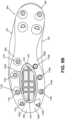
- Figs. 9A and 9B illustrate additional example articles of footwear 900, 950, sole structures 904, 954 and sole members 906, 956, in accordance with some examples of this technology.
- these example sole structures 904, 954 and sole members 906, 956 define an opening 1060 in the central space 104S defined between the interior-most extents of the primary traction elements 110L, 110M. Rather than a completely open opening 1060, however, the base surface 106S of the sole member 106 in these examples forms one or more support structures 910 across the opening 1060.
- One or more of the support structure(s) 910 may be integrally formed with the sole member 906, 956 and/or the sole structure 904, 954 when it is made (e.g., by molding techniques) and/or one or more of the support structure(s) 910 may be formed separately and then attached to the sole member 906, 956 and/or other part of the sole structure 904, 954 and/or footwear structure 900, 950 (e.g., by adhesives or cements, by mechanical fasteners, by fusing techniques, etc.).
- the projection field 200 is mounted inside the support structure(s) 910 so that the support structure(s) 910 is (are) exposed at the exterior of the sole structure 904.
- This mounting may be accomplished, e.g., with an assembly and structure like that shown in Fig. 2 (e.g., with the second surface 210G of the projection field 200 engaged with the interior surface 106I of the sole member 906).
- the second surface 210G of the projection field 200 will be engaged with the interior surface of the support structure(s) 910.
- the projection field 200 may be formed (e.g., during a molding process) to include one or more gaps between projections 202 and/or sets of projections 202 to accommodate placement and receipt of a corresponding support structure 910.
- projections 202 could be trimmed off an existing projection field 200 to provide gaps to accommodate the support structure 910 and/or projections 202 could be added to a projection field base 210B after the projection field 200 is engaged with the support structure 910, sole structure 904, and/or sole member 906.
- the projection field 200 is mounted outside the support structure(s) 910 so that the support structure(s) 910 is not (are not) exposed at the exterior of the sole structure 954. This mounting may be accomplished by engaging the first surface 210U of the projection field 200 with the exterior surface 106X of the sole member 956 and covering an opening 1060. Similarly, in this arrangement, the first surface 210U of the projection field 200 will be engaged with (and cover) the exterior surface of the support structure(s) 910 that extend across an opening 1060.
- the projection field 200 need not be formed to include one or more gaps between projections 202 and/or sets of projections 202 for support structure(s) 910 because the support structure(s) 910 are located inside the projection field 200.
- the base surface 106S of the sole member 906, 956 is formed to include a two-dimensional matrix or monolithic structure as the support structure 910 that extends across the opening 1060 to divide the opening 1060 into a plurality of openings separated by the matrix/monolithic structure.
- the support member(s) 910 may be positioned to provide a desired level of support across the opening 1060 while still accommodating transmission of forces from the projections 202 (e.g., due to contact with a ball) to the wearer's foot in the manner described above.
- the projections 202 included in sole structures 104, 404, 904, 954 in accordance with this technology are designed to readily bend under the weight of a wearer.
- the free ends 202E of the projections 202 are not intended to substantially penetrate and/or dig into the ground surface and/or to provide substantial traction for the wearer's foot by penetrating and/or digging into the ground surface.
- the projections 202 are intended to engage a ball (and potentially provide some ball gripping action) and help the user "feel" and control the ball and/or provide audio feedback of contact between the ball and the foot.
- the projections 202 and/or projection field 200 may be formed of or include a material that helps avoid dirt, grass, and other materials from sticking to them/it, such as a hydrophobic coating material.
- the projections 202 and/or projection field 200 may be formed from and/or treated by materials used in clog resistant and/or anti-clog soccer shoes available from NIKE, Inc. (and/or otherwise use the anti-clog structures and/or technology provided in such soccer shoes).
- Fig. 10 is similar to Figs. 2 and 3 , and where the same reference numbers are used in Fig. 10 as in Figs. 2 and/or 3 (and/or other figures), that reference number refers to the same part or a similar part (and the corresponding repetitive description is omitted).
- Figs. 2 and 3 show the projection field 200 as a separate part engaged with another sole member 104 part and/or a footwear upper 102 part (such as strobel 108).
- a footwear upper 102 part such as strobel 108
- the projection field 200 is integrally formed as part of a sole structure 104 component (e.g., integrally formed with an outsole component that includes primary traction elements 110L and 110M (or mounts therefor, if primary traction elements 110L and/or 110M are detachable) in this illustrated example).
- the projection field 200 may be integrally formed with at least one sole component part, e.g., by molding techniques (such as injection molding).
- the sole base 106S may include a "thinned area" corresponding to at least some portion of the projection field 200, e.g., the ground facing surface 210G.
- This "thinned area” may better transmit forces incident on the projections 202 (e.g., from contact with a ball) to the wearer's foot.
- These "integrally formed” projection field 200 features may be provided in any examples of the technology described above, and may include any options thereof, any projection shapes, any of the options in Tables 1-3, etc.
- Figs. 1A-9B show projection fields 200 devoid of primary traction elements, this is not a requirement.
- Fig. 10 further shows that the projection field 200 may include at least one primary traction element 110C within it (and optionally, two or more primary traction elements 110C). In this illustrated example, at least some of the projections 202, when fully extended, extend beyond the free end of the primary traction elements 110L, 110M, and/or 110C.
Landscapes
- Health & Medical Sciences (AREA)
- General Health & Medical Sciences (AREA)
- Physical Education & Sports Medicine (AREA)
- Footwear And Its Accessory, Manufacturing Method And Apparatuses (AREA)
Claims (15)
- Sohlenstruktur (104) mit einer dem Boden zugewandten Oberfläche und einer dem Oberteil zugewandten Oberfläche, wobei die Sohlenstruktur (104) umfasst:ein Sohlenelement (106, 406, 906, 956), das aus einem oder mehreren Teilen hergestellt ist und eine Grundfläche (106S), eine mediale Seite (106M) und eine laterale Seite (106L) enthält, wobei das Sohlenelement (106, 406, 906, 956) einen ersten Sohlenteil und ein Vorsprungsfeld (200), das mit dem ersten Sohlenteil in Eingriff steht oder einstückig damit ausgebildet ist, enthält, wobei das Vorsprungsfeld (200) eine Mehrzahl von Vorsprüngen (202) umfasst, die sich über die Grundfläche (106S) hinaus erstrecken und freiliegende freie Enden (202E) aufweisen, wobei die Mehrzahl von Vorsprüngen (202) mindestens 20 Vorsprünge (202) mit einer Vorsprungpackungsdichte von mindestens 0,62 Vorsprüngen (202) pro Quadratzentimeter (4 Vorsprünge (202) pro Quadratzoll) in dem Vorsprungsfeld (200) einschließt, wobei eine erste Untergruppe der Mehrzahl von Vorsprüngen (202) eine Länge von mindestens 5 mm aufweist, undwobei mindestens ein Großteil der Mehrzahl von Vorsprüngen (202) in dem Vorsprungsfeld (200) sich unter einer durch ein Gewicht eines Benutzers der Sohlenstruktur (104) aufgebrachten Kraft einfach verbiegt;wobei das Vorsprungsfeld (200) eine Vorsprungsfeldbasis (210B) mit einer ersten Oberfläche (210U) und einer zweiten Oberfläche (210G) gegenüber der ersten Oberfläche (210U) enthält, und wobei die Mehrzahl von Vorsprüngen (202) an der zweiten Oberfläche (210G) entspringt und sich von der Vorsprungsfeldbasis (210B) in einer Richtung weg von der ersten Oberfläche (210U) und der zweiten Oberfläche (210G) erstreckt;wobei die Grundfläche (106S) des Sohlenelements (106, 406, 906, 956) eine Innenfläche (1061) und eine Außenfläche (106X) gegenüber der Innenfläche (106I) enthält, wobei die Grundfläche (106S) eine durch sie hindurch definierte Öffnung (1060) aufweist, die sich vollständig von der Innenfläche (1061) zur Außenfläche (106X) erstreckt, wobei die zweite Oberfläche (210G) der Vorsprungsfeldbasis (210B) mit der Innenfläche (1061) der Grundfläche (106S) in Eingriff steht, und wobei sich die Mehrzahl von Vorsprüngen (202) durch die Öffnung (1060) erstreckt.
- Sohlenstruktur (104) nach Anspruch 1, weiter umfassend:eine Mehrzahl von primären Traktionselementen (110L, 110M), die sich in einer Richtung weg von der Grundfläche (106S) erstrecken, wobei sich jedes Traktionselement (110L, 110M) der Mehrzahl von primären Traktionselementen (110L, 110M) von der Grundfläche (106S) zu einer freien Endfläche erstreckt,wobei bei der Sohlenstruktur (104), die auf der dem Boden zugewandten Oberfläche auf einer horizontalen Stützfläche abgestützt ist, die erste Untergruppe der Mehrzahl von Vorsprüngen (202) eine Längslänge aufweist,wenn sie vollständig ausgedehnt ist, so dass sich ihre freien Enden (202E) in Richtung der horizontalen Stützfläche über das freie Ende eines dem jeweiligen Vorsprung (202) der ersten Untergruppe am nächsten liegenden primären Traktionselements (110L, 110M) hinaus erstrecken.
- Sohlenstruktur (104) nach Anspruch 1, weiter umfassend:eine Mehrzahl von medialseitigen primären Traktionselementen (110M), die auf der medialen Seite (106M) des Sohlenelements (106, 406, 906, 956) angeordnet sind und sich in einer Richtung weg von der Grundfläche (106S) erstrecken;eine Mehrzahl von lateralseitigen primären Traktionselementen (110L), die auf der lateralen Seite (106L) des Sohlenelements (106, 406, 906, 956) angeordnet sind und sich in einer Richtung weg von der Grundfläche (106S) erstrecken; undeinen zentralen Raum (104S), der zwischen inneren Ausdehnungen der Mehrzahl von medialseitigen primären Traktionselementen (110M) und der Mehrzahl von lateralseitigen primären Traktionselementen (110L) definiert ist,wobei das Vorsprungsfeld (200) zumindest teilweise in dem zentralen Raum (104S) angeordnet ist, wobei die Längen der ersten Untergruppe der Mehrzahl von Vorsprüngen (202) mindestens 8 mm betragen.
- Sohlenstruktur (104) nach Anspruch 1, weiter umfassend:eine Mehrzahl von medialseitigen primären Traktionselementen (110M), die auf der medialen Seite (106M) des Sohlenelements (106, 406, 906, 956) angeordnet sind und sich in einer Richtung weg von der Grundfläche (106S) erstrecken,wobei sich jedes Traktionselement (110M) der Mehrzahl von medialseitigen primären Traktionselementen (110M) von der Grundfläche (106S) zu einer freien Endfläche erstreckt;eine Mehrzahl von lateralseitigen primären Traktionselementen (110L), die auf der lateralen Seite (106L) des Sohlenelements (106, 406, 906, 956) angeordnet sind und sich in einer Richtung weg von der Grundfläche (106S) erstrecken,wobei sich jedes Traktionselement (110L) der Mehrzahl von lateralseitigen primären Traktionselementen (110L) von der Grundfläche (106S) zu einer freien Endfläche erstreckt; undeinen zentralen Raum (104S), der zwischen inneren Ausdehnungen der Mehrzahl von medialseitigen primären Traktionselementen (110M) und der Mehrzahl von lateralseitigen primären Traktionselementen (110L) definiert ist,wobei das Vorsprungsfeld (200) zumindest teilweise in dem zentralen Raum (104S) angeordnet ist, und wobei bei der Sohlenstruktur (104), die auf ihrer dem Boden zugewandten Oberfläche auf einer horizontalen Stützfläche abgestützt ist,die erste Untergruppe der Mehrzahl von Vorsprüngen (202) eine Längslänge aufweist, wenn sie vollständig ausgedehnt ist, so dass sich ihre freien Enden (202E) in Richtung der horizontalen Stützfläche über das freie Ende eines dem jeweiligen Vorsprung (202) der ersten Untergruppe am nächsten liegenden primären Traktionselements (110L, 110M) hinaus erstrecken.
- Sohlenstruktur (104) nach einem der Ansprüche 1 bis 4, wobei die Öffnung (106O) eine Größe von mindestens 2500 mm2 aufweist.
- Sohlenstruktur (104) nach einem der Ansprüche 1 bis 5, wobei die Grundfläche (106S) eine Matrixstruktur einschließt, die sich über die Öffnung (1060) erstreckt, um die Öffnung (1060) in eine Mehrzahl von Öffnungen zu unterteilen, die durch die Matrixstruktur getrennt sind, und wobei die zweite Oberfläche (210G) der Vorsprungsfeldbasis (210B) eine Innenfläche der Matrixstruktur berührt.
- Sohlenstruktur (104) nach einem der vorhergehenden Ansprüche, wobei eine Fläche, die innerhalb der äußersten Ausdehnungen der Mehrzahl von Vorsprüngen (202) in dem Vorsprungsfeld (200) definiert ist, mindestens 2400 mm2 umfasst.
- Sohlenstruktur (104) nach einem der vorhergehenden Ansprüche, wobei zumindest ein Großteil des Vorsprungsfeldes (200) in einem Vorfußbereich der Sohlenstruktur (104) angeordnet ist.
- Sohlenstruktur (104) nach einem der Ansprüche 1 bis 8, wobei sich das Vorsprungsfeld (200) kontinuierlich von einem Vorfußbereich zu einem Mittelfußbereich der Sohlenstruktur (104) erstreckt.
- Sohlenstruktur (104) nach einem der vorhergehenden Ansprüche, wobei mindestens 20 Vorsprünge (202) der Mehrzahl von Vorsprüngen (202) eine größte transversale Querschnittsabmessung von 8 mm oder weniger aufweisen.
- Sohlenstruktur (104) nach einem der Ansprüche 1 bis 9, wobei mindestens 20 Vorsprünge (202) der Mehrzahl von Vorsprüngen (202) eine größte transversale Querschnittsabmessung von 5 mm oder weniger aufweisen, oderwobei mindestens 20 Vorsprünge (202) der Mehrzahl von Vorsprüngen (202) eine abgerundete transversale Querschnittsform mit einem Durchmesser von 8 mm oder weniger aufweisen, oderwobei mindestens 20 Vorsprünge (202) der Mehrzahl von Vorsprüngen (202) eine abgerundete transversale Querschnittsform mit einem Durchmesser von 5 mm oder weniger aufweisen, oderwobei mindestens 20 Vorsprünge (202) der Mehrzahl von Vorsprüngen (202) eine abgerundete transversale Querschnittsform mit einem Durchmesser von 3 mm oder weniger aufweisen, oderwobei mindestens 20 Vorsprünge (202) der Mehrzahl von Vorsprüngen (202) eine polygonale transversale Querschnittsform mit einer größten Polygonseitenabmessung von 8 mm oder weniger aufweisen, oderwobei mindestens 20 Vorsprünge (202) der Mehrzahl von Vorsprüngen (202) eine rechteckige transversale Querschnittsform mit einer Breitseitenabmessung von 8 mm oder weniger und einer Schmalseitenabmessung von 4 mm oder weniger aufweisen, oderwobei mindestens 20 Vorsprünge (202) der Mehrzahl von Vorsprüngen (202) eine rechteckige transversale Querschnittsform mit einer Breitseitenabmessung von 6 mm oder weniger und einer Schmalseitenabmessung von 3 mm oder weniger aufweisen,wobei sich optional die mindestens 20 Vorsprünge (202) in ihren Längsabmessungen in ihrer Querschnittsform auf eine kleinste transversale Querschnittsgröße an den freien Enden (202E) der jeweiligen Vorsprünge (202) verjüngen.
- Sohlenkonstruktion (104) nach einem der vorhergehenden Ansprüche, weiter umfassend ein intermediäres primäres Traktionselement, das innerhalb des Vorsprungsfeldes (200) angeordnet ist.
- Sohlenstruktur (104) nach einem der Ansprüche 1 bis 11, wobei das Vorsprungsfeld (200) frei von primären Traktionselementen ist.
- Sohlenstruktur (104) nach Anspruch 2, wobei sich ein Teil des Vorsprungsfeldes (200) zwischen mindestens zwei der Mehrzahl von primären Traktionselementen (110L, 110M) auf einer Seite des Sohlenelements (106, 406, 906, 956) erstreckt.
- Schuhwerk (100), umfassend:ein Oberteil (102); undeine Sohlenstruktur (104) nach einem der vorhergehenden Ansprüche, die mit dem Oberteil (102) in Eingriff steht.
Applications Claiming Priority (2)
| Application Number | Priority Date | Filing Date | Title |
|---|---|---|---|
| US201962930890P | 2019-11-05 | 2019-11-05 | |
| PCT/US2020/059051 WO2021092133A1 (en) | 2019-11-05 | 2020-11-05 | Foot support components for articles of footwear including multiple flexible projections at the ground-facing surface |
Publications (2)
| Publication Number | Publication Date |
|---|---|
| EP4054375A1 EP4054375A1 (de) | 2022-09-14 |
| EP4054375B1 true EP4054375B1 (de) | 2025-07-02 |
Family
ID=73695133
Family Applications (1)
| Application Number | Title | Priority Date | Filing Date |
|---|---|---|---|
| EP20817559.6A Active EP4054375B1 (de) | 2019-11-05 | 2020-11-05 | Fussstützenkomponente für schuhwerk mit mehreren flexiblen vorsprüngen an der bodenseitigen oberfläche |
Country Status (3)
| Country | Link |
|---|---|
| US (2) | US12102174B2 (de) |
| EP (1) | EP4054375B1 (de) |
| WO (1) | WO2021092133A1 (de) |
Families Citing this family (3)
| Publication number | Priority date | Publication date | Assignee | Title |
|---|---|---|---|---|
| USD974013S1 (en) * | 2021-06-25 | 2023-01-03 | Shengtong Ji | Football sole with spikes |
| US12440736B2 (en) * | 2022-10-13 | 2025-10-14 | Andres F. GARCIA | Golf cleat with integrated bristles |
| US20260041197A1 (en) * | 2024-08-06 | 2026-02-12 | Nike, Inc. | Sole structure for article of footwear |
Citations (1)
| Publication number | Priority date | Publication date | Assignee | Title |
|---|---|---|---|---|
| US20120023781A1 (en) * | 2010-07-30 | 2012-02-02 | Nike, Inc. | Wear-resistant outsole |
Family Cites Families (48)
| Publication number | Priority date | Publication date | Assignee | Title |
|---|---|---|---|---|
| US2985971A (en) * | 1960-08-24 | 1961-05-30 | Steven A Murawski | Flexible resilient footwear |
| US3463165A (en) * | 1967-05-29 | 1969-08-26 | Joseph P Goodman | Orthopedic shoe |
| GB1180708A (en) * | 1967-09-20 | 1970-02-11 | Dassler Puma Sportschuh | Improvements in and relating to Sports Shoes, particularly Track Shoes |
| US3583082A (en) * | 1969-09-29 | 1971-06-08 | George Payton Jordan Jr | Track shoe cleats |
| DE7023257U (de) * | 1970-06-20 | 1971-03-18 | Birkenstock K | Sohle, insbesondere für Sandalen |
| JPS5113603B1 (de) * | 1971-10-20 | 1976-05-01 | ||
| US3849915A (en) * | 1973-01-31 | 1974-11-26 | Onitsuka Co Ltd | Sport shoe |
| US3932950A (en) * | 1974-11-14 | 1976-01-20 | Tractioneers, Inc. | Footwear with non-slip tread |
| DE7728190U1 (de) * | 1977-09-12 | 1977-12-22 | Froer, Werner, 8520 Erlangen | Sportschuhlaufsohle |
| DE2927704C2 (de) * | 1979-07-09 | 1982-03-25 | Puma-Sportschuhfabriken Rudolf Dassler Kg, 8522 Herzogenaurach | Aus Gummi oder einem anderen Werkstoff mit gummielastischen Eigenschaften bestehende Laufsohle für Schuhe, insbesondere Sportschuhe |
| US4327503A (en) * | 1980-01-17 | 1982-05-04 | Brs, Inc. | Outer sole structure for athletic shoe |
| US4378643A (en) * | 1980-01-17 | 1983-04-05 | Brs, Inc. | Sole with skewed cleating arrangement |
| DE3032268A1 (de) * | 1980-08-27 | 1982-04-08 | Puma-Sportschuhfabriken Rudolf Dassler Kg, 8522 Herzogenaurach | Aus gummi oder einem anderen material mit gummielastischen eigenschaften bestehende laufsohle fuer sportschuhe |
| US4356643A (en) * | 1980-11-28 | 1982-11-02 | Kester Adelbert L | Non-slip footwear |
| US4439936A (en) * | 1982-06-03 | 1984-04-03 | Nike, Inc. | Shock attenuating outer sole |
| GB2122872B (en) * | 1982-06-09 | 1985-10-09 | Griplite S L | Sports shoes |
| US4624062A (en) * | 1985-06-17 | 1986-11-25 | Autry Industries, Inc. | Sole with cushioning and braking spiroidal contact surfaces |
| FR2632497A1 (fr) * | 1988-03-22 | 1989-12-15 | Beneteau Charles Marie | Semelle de chaussures pour la pratique des sports et activites analogues |
| US5313718A (en) * | 1988-10-07 | 1994-05-24 | Nike, Inc. | Athletic shoe with bendable traction projections |
| US5265354A (en) * | 1989-11-28 | 1993-11-30 | Aliano Jr Joseph F | Golf shoe insert |
| US5293701A (en) * | 1990-03-19 | 1994-03-15 | Sullivan William W | Convertible footwear |
| JPH084523B2 (ja) * | 1992-05-13 | 1996-01-24 | 株式会社アシックス | 陸上競技用スパイクシューズの硬質板 |
| JP2824500B2 (ja) * | 1994-02-17 | 1998-11-11 | 株式会社アシックス | 陸上競技用スパイクシューズの硬質板 |
| US5775005A (en) * | 1995-06-21 | 1998-07-07 | Wolverine World Wide Inc. | Footwear sole with cleated window |
| US5761833A (en) * | 1995-12-22 | 1998-06-09 | Softspikes, Inc. | Athletic shoe traction system for use on turf |
| US5836091A (en) * | 1996-09-04 | 1998-11-17 | Cook; Michael H. | Traction enhancing articles of manufacture |
| US6032386A (en) * | 1998-06-23 | 2000-03-07 | Partners In Innovation, Llc | Golf shoe with removable sole |
| US6076283A (en) * | 1998-11-30 | 2000-06-20 | Srl, Inc. | Shoes and shoe outsoles for wet surfaces |
| US6948264B1 (en) * | 2000-04-26 | 2005-09-27 | Lyden Robert M | Non-clogging sole for article of footwear |
| US9894955B2 (en) * | 2002-07-31 | 2018-02-20 | Dynasty Footwear, Ltd. | Shoe having individual particles bonded to its bottom surface |
| JP3096646U (ja) * | 2003-02-26 | 2003-09-26 | 堂模 潘 | 靴の滑り防止構造 |
| WO2005029993A1 (en) * | 2003-09-25 | 2005-04-07 | The Timberland Company | Footwear with articulating outsole lugs |
| US7347011B2 (en) | 2004-03-03 | 2008-03-25 | Nike, Inc. | Article of footwear having a textile upper |
| US20060005425A1 (en) * | 2004-07-12 | 2006-01-12 | Votolato Earl J | Elastic overshoe with slip resistant sole pads |
| US7370439B1 (en) * | 2004-07-19 | 2008-05-13 | Myers Robert J | Field and stream boot |
| CN101128131A (zh) * | 2005-02-24 | 2008-02-20 | 格莱登制锁有限公司 | 具有切向变形能力的外底 |
| US20070130801A1 (en) * | 2005-12-08 | 2007-06-14 | Kun-Ho Wu | Combination outsole and friction sheet |
| US7707748B2 (en) * | 2006-02-24 | 2010-05-04 | Nike, Inc. | Flexible foot-support structures and products containing such support structures |
| EP2674051B1 (de) * | 2007-02-28 | 2018-12-26 | NIKE Innovate C.V. | Schuhartikel mit einer Sohlenstruktur aus polygonalen Laschen |
| US7762009B2 (en) * | 2007-03-12 | 2010-07-27 | Nike, Inc. | Article of footwear with circular tread pattern |
| US7832120B2 (en) * | 2007-10-08 | 2010-11-16 | Man-Young Jung | Anti-slip footwear |
| US8429835B2 (en) | 2009-10-21 | 2013-04-30 | Nike, Inc. | Composite shoe upper and method of making same |
| US9210967B2 (en) * | 2010-08-13 | 2015-12-15 | Nike, Inc. | Sole structure with traction elements |
| US9414638B2 (en) | 2011-08-02 | 2016-08-16 | Nike, Inc. | Golf shoe with natural motion structures |
| KR101309711B1 (ko) | 2011-08-30 | 2013-09-23 | 주식회사 에이스하이텍 | 다기능 골프화 |
| GB201208020D0 (en) * | 2012-05-08 | 2012-06-20 | Facetsgroup Man Ltd | Ice grips |
| US9516917B2 (en) * | 2014-01-16 | 2016-12-13 | Nike, Inc. | Sole system having protruding members |
| US9532623B2 (en) * | 2014-02-07 | 2017-01-03 | Nike, Inc. | Sole structure for an article of footwear with extended plate |
-
2020
- 2020-11-04 US US17/089,091 patent/US12102174B2/en active Active
- 2020-11-05 EP EP20817559.6A patent/EP4054375B1/de active Active
- 2020-11-05 WO PCT/US2020/059051 patent/WO2021092133A1/en not_active Ceased
-
2024
- 2024-08-13 US US18/802,102 patent/US20240398064A1/en active Pending
Patent Citations (1)
| Publication number | Priority date | Publication date | Assignee | Title |
|---|---|---|---|---|
| US20120023781A1 (en) * | 2010-07-30 | 2012-02-02 | Nike, Inc. | Wear-resistant outsole |
Also Published As
| Publication number | Publication date |
|---|---|
| US20210127785A1 (en) | 2021-05-06 |
| WO2021092133A1 (en) | 2021-05-14 |
| EP4054375A1 (de) | 2022-09-14 |
| US12102174B2 (en) | 2024-10-01 |
| US20240398064A1 (en) | 2024-12-05 |
Similar Documents
| Publication | Publication Date | Title |
|---|---|---|
| US12127628B2 (en) | Article of footwear with multiple durometer outsole | |
| US11896081B2 (en) | Article with sole structure having multiple components | |
| US10182611B2 (en) | Article of footwear with flexible reinforcing plate | |
| US11957208B2 (en) | Sole structures having multiple hardnesses and/or flex promoting structures | |
| US11503877B2 (en) | Article of footwear and sole structure with a central forefoot ridge element | |
| US20240398064A1 (en) | Foot Support Components for Articles of Footwear Including Multiple Flexible Projections at the Ground-Facing Surface | |
| US9750304B2 (en) | Article of footwear having talonavicular support |
Legal Events
| Date | Code | Title | Description |
|---|---|---|---|
| STAA | Information on the status of an ep patent application or granted ep patent |
Free format text: STATUS: UNKNOWN |
|
| STAA | Information on the status of an ep patent application or granted ep patent |
Free format text: STATUS: THE INTERNATIONAL PUBLICATION HAS BEEN MADE |
|
| PUAI | Public reference made under article 153(3) epc to a published international application that has entered the european phase |
Free format text: ORIGINAL CODE: 0009012 |
|
| STAA | Information on the status of an ep patent application or granted ep patent |
Free format text: STATUS: REQUEST FOR EXAMINATION WAS MADE |
|
| 17P | Request for examination filed |
Effective date: 20220203 |
|
| AK | Designated contracting states |
Kind code of ref document: A1 Designated state(s): AL AT BE BG CH CY CZ DE DK EE ES FI FR GB GR HR HU IE IS IT LI LT LU LV MC MK MT NL NO PL PT RO RS SE SI SK SM TR |
|
| DAV | Request for validation of the european patent (deleted) | ||
| DAX | Request for extension of the european patent (deleted) | ||
| P01 | Opt-out of the competence of the unified patent court (upc) registered |
Effective date: 20230515 |
|
| STAA | Information on the status of an ep patent application or granted ep patent |
Free format text: STATUS: EXAMINATION IS IN PROGRESS |
|
| 17Q | First examination report despatched |
Effective date: 20230830 |
|
| REG | Reference to a national code |
Ref country code: DE Ref legal event code: R079 Free format text: PREVIOUS MAIN CLASS: A43B0013260000 Ipc: A43B0005020000 Ref country code: DE Ref legal event code: R079 Ref document number: 602020053926 Country of ref document: DE Free format text: PREVIOUS MAIN CLASS: A43B0013260000 Ipc: A43B0005020000 |
|
| GRAP | Despatch of communication of intention to grant a patent |
Free format text: ORIGINAL CODE: EPIDOSNIGR1 |
|
| STAA | Information on the status of an ep patent application or granted ep patent |
Free format text: STATUS: GRANT OF PATENT IS INTENDED |
|
| RIC1 | Information provided on ipc code assigned before grant |
Ipc: A43C 15/16 20060101ALI20250116BHEP Ipc: A43B 13/26 20060101ALI20250116BHEP Ipc: A43B 5/02 20060101AFI20250116BHEP |
|
| INTG | Intention to grant announced |
Effective date: 20250128 |
|
| GRAS | Grant fee paid |
Free format text: ORIGINAL CODE: EPIDOSNIGR3 |
|
| GRAA | (expected) grant |
Free format text: ORIGINAL CODE: 0009210 |
|
| STAA | Information on the status of an ep patent application or granted ep patent |
Free format text: STATUS: THE PATENT HAS BEEN GRANTED |
|
| AK | Designated contracting states |
Kind code of ref document: B1 Designated state(s): AL AT BE BG CH CY CZ DE DK EE ES FI FR GB GR HR HU IE IS IT LI LT LU LV MC MK MT NL NO PL PT RO RS SE SI SK SM TR |
|
| REG | Reference to a national code |
Ref country code: GB Ref legal event code: FG4D |
|
| REG | Reference to a national code |
Ref country code: CH Ref legal event code: EP |
|
| REG | Reference to a national code |
Ref country code: DE Ref legal event code: R096 Ref document number: 602020053926 Country of ref document: DE |
|
| REG | Reference to a national code |
Ref country code: IE Ref legal event code: FG4D |
|
| PGFP | Annual fee paid to national office [announced via postgrant information from national office to epo] |
Ref country code: GB Payment date: 20250911 Year of fee payment: 6 |
|
| PGFP | Annual fee paid to national office [announced via postgrant information from national office to epo] |
Ref country code: FR Payment date: 20250908 Year of fee payment: 6 |
|
| REG | Reference to a national code |
Ref country code: NL Ref legal event code: MP Effective date: 20250702 |
|
| PG25 | Lapsed in a contracting state [announced via postgrant information from national office to epo] |
Ref country code: PT Free format text: LAPSE BECAUSE OF FAILURE TO SUBMIT A TRANSLATION OF THE DESCRIPTION OR TO PAY THE FEE WITHIN THE PRESCRIBED TIME-LIMIT Effective date: 20251103 |
|
| PG25 | Lapsed in a contracting state [announced via postgrant information from national office to epo] |
Ref country code: NL Free format text: LAPSE BECAUSE OF FAILURE TO SUBMIT A TRANSLATION OF THE DESCRIPTION OR TO PAY THE FEE WITHIN THE PRESCRIBED TIME-LIMIT Effective date: 20250702 |
|
| REG | Reference to a national code |
Ref country code: AT Ref legal event code: MK05 Ref document number: 1808197 Country of ref document: AT Kind code of ref document: T Effective date: 20250702 |
|
| PG25 | Lapsed in a contracting state [announced via postgrant information from national office to epo] |
Ref country code: IS Free format text: LAPSE BECAUSE OF FAILURE TO SUBMIT A TRANSLATION OF THE DESCRIPTION OR TO PAY THE FEE WITHIN THE PRESCRIBED TIME-LIMIT Effective date: 20251102 |
|
| PGFP | Annual fee paid to national office [announced via postgrant information from national office to epo] |
Ref country code: DE Payment date: 20250910 Year of fee payment: 6 |
|
| PG25 | Lapsed in a contracting state [announced via postgrant information from national office to epo] |
Ref country code: NO Free format text: LAPSE BECAUSE OF FAILURE TO SUBMIT A TRANSLATION OF THE DESCRIPTION OR TO PAY THE FEE WITHIN THE PRESCRIBED TIME-LIMIT Effective date: 20251002 |
|
| REG | Reference to a national code |
Ref country code: LT Ref legal event code: MG9D |
|
| PG25 | Lapsed in a contracting state [announced via postgrant information from national office to epo] |
Ref country code: AT Free format text: LAPSE BECAUSE OF FAILURE TO SUBMIT A TRANSLATION OF THE DESCRIPTION OR TO PAY THE FEE WITHIN THE PRESCRIBED TIME-LIMIT Effective date: 20250702 |
|
| PG25 | Lapsed in a contracting state [announced via postgrant information from national office to epo] |
Ref country code: FI Free format text: LAPSE BECAUSE OF FAILURE TO SUBMIT A TRANSLATION OF THE DESCRIPTION OR TO PAY THE FEE WITHIN THE PRESCRIBED TIME-LIMIT Effective date: 20250702 |
|
| PG25 | Lapsed in a contracting state [announced via postgrant information from national office to epo] |
Ref country code: HR Free format text: LAPSE BECAUSE OF FAILURE TO SUBMIT A TRANSLATION OF THE DESCRIPTION OR TO PAY THE FEE WITHIN THE PRESCRIBED TIME-LIMIT Effective date: 20250702 |
|
| PG25 | Lapsed in a contracting state [announced via postgrant information from national office to epo] |
Ref country code: GR Free format text: LAPSE BECAUSE OF FAILURE TO SUBMIT A TRANSLATION OF THE DESCRIPTION OR TO PAY THE FEE WITHIN THE PRESCRIBED TIME-LIMIT Effective date: 20251003 |
|
| PG25 | Lapsed in a contracting state [announced via postgrant information from national office to epo] |
Ref country code: CZ Free format text: LAPSE BECAUSE OF FAILURE TO SUBMIT A TRANSLATION OF THE DESCRIPTION OR TO PAY THE FEE WITHIN THE PRESCRIBED TIME-LIMIT Effective date: 20250702 Ref country code: SE Free format text: LAPSE BECAUSE OF FAILURE TO SUBMIT A TRANSLATION OF THE DESCRIPTION OR TO PAY THE FEE WITHIN THE PRESCRIBED TIME-LIMIT Effective date: 20250702 |
|
| PG25 | Lapsed in a contracting state [announced via postgrant information from national office to epo] |
Ref country code: LV Free format text: LAPSE BECAUSE OF FAILURE TO SUBMIT A TRANSLATION OF THE DESCRIPTION OR TO PAY THE FEE WITHIN THE PRESCRIBED TIME-LIMIT Effective date: 20250702 |
|
| PG25 | Lapsed in a contracting state [announced via postgrant information from national office to epo] |
Ref country code: BG Free format text: LAPSE BECAUSE OF FAILURE TO SUBMIT A TRANSLATION OF THE DESCRIPTION OR TO PAY THE FEE WITHIN THE PRESCRIBED TIME-LIMIT Effective date: 20250702 Ref country code: PL Free format text: LAPSE BECAUSE OF FAILURE TO SUBMIT A TRANSLATION OF THE DESCRIPTION OR TO PAY THE FEE WITHIN THE PRESCRIBED TIME-LIMIT Effective date: 20250702 |
|
| PG25 | Lapsed in a contracting state [announced via postgrant information from national office to epo] |
Ref country code: RS Free format text: LAPSE BECAUSE OF FAILURE TO SUBMIT A TRANSLATION OF THE DESCRIPTION OR TO PAY THE FEE WITHIN THE PRESCRIBED TIME-LIMIT Effective date: 20251002 |
|
| PG25 | Lapsed in a contracting state [announced via postgrant information from national office to epo] |
Ref country code: ES Free format text: LAPSE BECAUSE OF FAILURE TO SUBMIT A TRANSLATION OF THE DESCRIPTION OR TO PAY THE FEE WITHIN THE PRESCRIBED TIME-LIMIT Effective date: 20250702 |
|
| PG25 | Lapsed in a contracting state [announced via postgrant information from national office to epo] |
Ref country code: RO Free format text: LAPSE BECAUSE OF FAILURE TO SUBMIT A TRANSLATION OF THE DESCRIPTION OR TO PAY THE FEE WITHIN THE PRESCRIBED TIME-LIMIT Effective date: 20250702 |
|
| PG25 | Lapsed in a contracting state [announced via postgrant information from national office to epo] |
Ref country code: SM Free format text: LAPSE BECAUSE OF FAILURE TO SUBMIT A TRANSLATION OF THE DESCRIPTION OR TO PAY THE FEE WITHIN THE PRESCRIBED TIME-LIMIT Effective date: 20250702 |
|
| PG25 | Lapsed in a contracting state [announced via postgrant information from national office to epo] |
Ref country code: DK Free format text: LAPSE BECAUSE OF FAILURE TO SUBMIT A TRANSLATION OF THE DESCRIPTION OR TO PAY THE FEE WITHIN THE PRESCRIBED TIME-LIMIT Effective date: 20250702 |
|
| PG25 | Lapsed in a contracting state [announced via postgrant information from national office to epo] |
Ref country code: IT Free format text: LAPSE BECAUSE OF FAILURE TO SUBMIT A TRANSLATION OF THE DESCRIPTION OR TO PAY THE FEE WITHIN THE PRESCRIBED TIME-LIMIT Effective date: 20250702 |
|
| PG25 | Lapsed in a contracting state [announced via postgrant information from national office to epo] |
Ref country code: SK Free format text: LAPSE BECAUSE OF FAILURE TO SUBMIT A TRANSLATION OF THE DESCRIPTION OR TO PAY THE FEE WITHIN THE PRESCRIBED TIME-LIMIT Effective date: 20250702 Ref country code: EE Free format text: LAPSE BECAUSE OF FAILURE TO SUBMIT A TRANSLATION OF THE DESCRIPTION OR TO PAY THE FEE WITHIN THE PRESCRIBED TIME-LIMIT Effective date: 20250702 |
|
| PLBE | No opposition filed within time limit |
Free format text: ORIGINAL CODE: 0009261 |
|
| STAA | Information on the status of an ep patent application or granted ep patent |
Free format text: STATUS: NO OPPOSITION FILED WITHIN TIME LIMIT |