EP4054827B1 - Procédé et appareil de traitement d'un matériau optiquement réactif - Google Patents
Procédé et appareil de traitement d'un matériau optiquement réactif Download PDFInfo
- Publication number
- EP4054827B1 EP4054827B1 EP20807657.0A EP20807657A EP4054827B1 EP 4054827 B1 EP4054827 B1 EP 4054827B1 EP 20807657 A EP20807657 A EP 20807657A EP 4054827 B1 EP4054827 B1 EP 4054827B1
- Authority
- EP
- European Patent Office
- Prior art keywords
- light
- volume
- wavelength
- starting material
- layer
- Prior art date
- Legal status (The legal status is an assumption and is not a legal conclusion. Google has not performed a legal analysis and makes no representation as to the accuracy of the status listed.)
- Active
Links
Images



Classifications
-
- B—PERFORMING OPERATIONS; TRANSPORTING
- B29—WORKING OF PLASTICS; WORKING OF SUBSTANCES IN A PLASTIC STATE IN GENERAL
- B29C—SHAPING OR JOINING OF PLASTICS; SHAPING OF MATERIAL IN A PLASTIC STATE, NOT OTHERWISE PROVIDED FOR; AFTER-TREATMENT OF THE SHAPED PRODUCTS, e.g. REPAIRING
- B29C64/00—Additive manufacturing, i.e. manufacturing of three-dimensional [3D] objects by additive deposition, additive agglomeration or additive layering, e.g. by 3D printing, stereolithography or selective laser sintering
- B29C64/10—Processes of additive manufacturing
- B29C64/106—Processes of additive manufacturing using only liquids or viscous materials, e.g. depositing a continuous bead of viscous material
- B29C64/124—Processes of additive manufacturing using only liquids or viscous materials, e.g. depositing a continuous bead of viscous material using layers of liquid which are selectively solidified
- B29C64/129—Processes of additive manufacturing using only liquids or viscous materials, e.g. depositing a continuous bead of viscous material using layers of liquid which are selectively solidified characterised by the energy source therefor, e.g. by global irradiation combined with a mask
- B29C64/135—Processes of additive manufacturing using only liquids or viscous materials, e.g. depositing a continuous bead of viscous material using layers of liquid which are selectively solidified characterised by the energy source therefor, e.g. by global irradiation combined with a mask the energy source being concentrated, e.g. scanning lasers or focused light sources
-
- B—PERFORMING OPERATIONS; TRANSPORTING
- B29—WORKING OF PLASTICS; WORKING OF SUBSTANCES IN A PLASTIC STATE IN GENERAL
- B29C—SHAPING OR JOINING OF PLASTICS; SHAPING OF MATERIAL IN A PLASTIC STATE, NOT OTHERWISE PROVIDED FOR; AFTER-TREATMENT OF THE SHAPED PRODUCTS, e.g. REPAIRING
- B29C64/00—Additive manufacturing, i.e. manufacturing of three-dimensional [3D] objects by additive deposition, additive agglomeration or additive layering, e.g. by 3D printing, stereolithography or selective laser sintering
- B29C64/10—Processes of additive manufacturing
- B29C64/106—Processes of additive manufacturing using only liquids or viscous materials, e.g. depositing a continuous bead of viscous material
- B29C64/124—Processes of additive manufacturing using only liquids or viscous materials, e.g. depositing a continuous bead of viscous material using layers of liquid which are selectively solidified
- B29C64/129—Processes of additive manufacturing using only liquids or viscous materials, e.g. depositing a continuous bead of viscous material using layers of liquid which are selectively solidified characterised by the energy source therefor, e.g. by global irradiation combined with a mask
-
- B—PERFORMING OPERATIONS; TRANSPORTING
- B29—WORKING OF PLASTICS; WORKING OF SUBSTANCES IN A PLASTIC STATE IN GENERAL
- B29C—SHAPING OR JOINING OF PLASTICS; SHAPING OF MATERIAL IN A PLASTIC STATE, NOT OTHERWISE PROVIDED FOR; AFTER-TREATMENT OF THE SHAPED PRODUCTS, e.g. REPAIRING
- B29C64/00—Additive manufacturing, i.e. manufacturing of three-dimensional [3D] objects by additive deposition, additive agglomeration or additive layering, e.g. by 3D printing, stereolithography or selective laser sintering
- B29C64/20—Apparatus for additive manufacturing; Details thereof or accessories therefor
- B29C64/264—Arrangements for irradiation
-
- B—PERFORMING OPERATIONS; TRANSPORTING
- B29—WORKING OF PLASTICS; WORKING OF SUBSTANCES IN A PLASTIC STATE IN GENERAL
- B29C—SHAPING OR JOINING OF PLASTICS; SHAPING OF MATERIAL IN A PLASTIC STATE, NOT OTHERWISE PROVIDED FOR; AFTER-TREATMENT OF THE SHAPED PRODUCTS, e.g. REPAIRING
- B29C64/00—Additive manufacturing, i.e. manufacturing of three-dimensional [3D] objects by additive deposition, additive agglomeration or additive layering, e.g. by 3D printing, stereolithography or selective laser sintering
- B29C64/20—Apparatus for additive manufacturing; Details thereof or accessories therefor
- B29C64/264—Arrangements for irradiation
- B29C64/277—Arrangements for irradiation using multiple radiation means, e.g. micromirrors or multiple light-emitting diodes [LED]
-
- B—PERFORMING OPERATIONS; TRANSPORTING
- B33—ADDITIVE MANUFACTURING TECHNOLOGY
- B33Y—ADDITIVE MANUFACTURING, i.e. MANUFACTURING OF THREE-DIMENSIONAL [3D] OBJECTS BY ADDITIVE DEPOSITION, ADDITIVE AGGLOMERATION OR ADDITIVE LAYERING, e.g. BY 3D PRINTING, STEREOLITHOGRAPHY OR SELECTIVE LASER SINTERING
- B33Y10/00—Processes of additive manufacturing
-
- B—PERFORMING OPERATIONS; TRANSPORTING
- B33—ADDITIVE MANUFACTURING TECHNOLOGY
- B33Y—ADDITIVE MANUFACTURING, i.e. MANUFACTURING OF THREE-DIMENSIONAL [3D] OBJECTS BY ADDITIVE DEPOSITION, ADDITIVE AGGLOMERATION OR ADDITIVE LAYERING, e.g. BY 3D PRINTING, STEREOLITHOGRAPHY OR SELECTIVE LASER SINTERING
- B33Y30/00—Apparatus for additive manufacturing; Details thereof or accessories therefor
Definitions
- the invention relates to a method and a device for processing an optically reactive material.
- Starting materials can be processed optically, i.e. by radiating light of one or more wavelengths onto the starting material in order to thereby change at least one material property of the starting material. For example, it is known as such to harden a starting material with the aid of such optical processing.
- a method for producing a printable 3D nanostructure comprising: a first light source configured to bring a polymer medium into an excited state via a dynamic light-space modulation element to initiate polymerization; a second light source configured to selectively apply inhibitory energy to the polymerized medium to inhibit polymerization, thereby creating a dead zone below a growth zone that enables continuous 3D polymerization.
- an additive manufacturing device comprising: a platform, a dispenser configured to deliver multiple successive layers of a feed material to the platform, a light source assembly for generating a first light beam and a second light beam, a beam combiner configured to combine the first light and the second light into a common light beam, and a mirror scanner configured to direct the common light beam toward the platform to generate energy along a scanning path on an outermost layer of the feed material.
- Polymerization is a reaction used to make plastics.
- photopolymerization which is a form of optical processing of a starting material
- the reaction is triggered by shining light onto the polymerizable starting material.
- Such polymerizable starting materials or materials are also referred to as photopolymer.
- This is a polymer that changes its material properties when it is irradiated with light. Exposure to light causes structural changes, such as photochemical hardening of the material through crosslinking.
- Photopolymerization is used, for example, in 3D printing to produce three-dimensional shaped bodies from the cured material by irradiating light into the polymerizable starting material.
- the starting material itself can be transparent to the irradiated light and therefore insensitive.
- Photoinitiator molecules are added, which absorb the light and initiate the curing of the starting material.
- To process the source material in an unchanged (free) volume it is necessary to address a freely chosen point in 3-dimensional space.
- One possibility is to use special photoinitiators, also known as dual-color photoinitiators. These are preferably or exclusively excited by absorption of photons of two different wavelengths.
- Dual-color photoinitiators can be created in different ways; in one variant, molecules have a ground/normal state (A) without light irradiation. In this state, the molecule has an absorption band for one wavelength ⁇ 1 and the lowest possible absorption at another wavelength ⁇ 2 .
- the molecules can then assume a preactivated or excited intermediate state (B).
- the excited intermediate state is generated by absorbing light of wavelength ⁇ 1 from the ground state A.
- the photoinitiator molecules have an absorption band for wavelength ⁇ 2 .
- the absorption band for the wavelength ⁇ 1 disappears.
- the absorption band for the wavelength ⁇ 1 is retained. This creates an undesirable, competing transition channel to state C.
- the photoinitiator molecule returns to state A in the absence of light.
- the photoinitiator molecule returns to state A after excitation with light of a third wavelength ⁇ 3 . This allows targeted inhibition of the initiator in state B.
- the active state C of the molecules is created by absorption of the wavelength ⁇ 2 from B. State C initiates a chemical and/or physical modification of the molecule's immediate environment. A reverse reaction to B is not planned but possible.
- the document WO 2019 / 194 798 A1 discloses an apparatus and method for forming a three-dimensional component.
- the method includes filling a container with a volume of curable resin, the resin configured to undergo a first reaction to form a first product when exposed to light of a first wavelength and to undergo a second reaction , to form a second product when exposed to light of a second wavelength.
- the presence of the first and second products at a common location in the resin triggers a third reaction that results in a solid polymer at the common location.
- the method further includes directing a first light source of the first wavelength into the container, directing a second light source of the second wavelength into the container such that the first and second light sources intersect at a first predetermined location within the container, and enabling the third reaction to form the solid polymer at the first predetermined location.
- the object of the invention is to provide a method and a device for processing an optically reactive material, with which a starting material can be optically processed in a multi-dimensional manner in an efficient manner.
- the layer partial volumes of the working volume are irradiated one after the other with the first and second wavelengths in order to trigger an optically initiated reaction in the starting material.
- the layer partial volumes which are optically processed one after the other, contain partial volumes of the starting material that is introduced into the working volume before the start of the manufacturing process (optical processing) and are filled by them.
- optical processing there is no layer-by-layer application of the starting material and subsequent layer-by-layer optical processing (of the layer that has just been applied) after the layer application.
- the light of the second wavelength is projected using the projection device into exactly this layer sub-volume that is currently and currently irradiated with the first wavelength.
- the projection device causes the light of the second wavelength to be imaged into the currently desired partial layer volume.
- the projection device can image the light of the second wavelength of an at least two-dimensionally shaped image into the projection plane or the projection volume, which is located in the layer sub-volume irradiated with the light of the first wavelength. In this way, for example, a three-dimensional body can be produced layer by layer in the starting material.
- a control device which is connected to one or more light sources for providing the light of the first and the second wavelength and the projection device, it can be determined whether the first or the second layer sub-volume (of the starting material in the working volume) is irradiated, and the projection device can be controlled depending on this to project the light of the second wavelength into the first or the second layer sub-volume.
- Data is provided in the control device which defines the current or instantaneous position of the partial layer volume which is irradiated with light of the first wavelength. Based on this, the projection device is controlled in such a way that the projection generated with the help of the projection device is currently in a projection plane or in a projection volume irradiated layer partial volume takes place.
- the layer partial volumes of the starting material are processed one after the other, layer by layer.
- the external shape of the projection of the projection device can be different for different layer partial volumes, in particular depending on a three-dimensional body that is to be produced in the starting material with the aid of optical processing.
- it can be provided to detect a current or instantaneous position of the layer partial volume, which is irradiated with the light of the first wavelength, in the working volume with the aid of a measuring device, which then sends measurement signals indicating the position to the control device.
- the light of the first wavelength and the light of the second wavelength can be simultaneously irradiated together into the first or the second layer sub-volume at least for a time overlapping period.
- the area captured by the layer partial volume and the projection of the projection device is irradiated with both light of the first wavelength and with light of the second wavelength, at least for the temporal overlap area.
- the first and second layer sub-volumes can form adjacent layer sub-volumes of the starting material in the working volume.
- first and second layer sub-volumes are formed in accordance with one of the following configurations of sub-volumes: overlapping on the edge, abutting on the edge and spaced apart from one another on the edge.
- the light of the first wavelength can be irradiated onto the starting material in the working volume along a first irradiation direction and the light of the second wavelength can be irradiated along a second irradiation direction, which runs transversely to the first irradiation direction.
- the first and second irradiation directions can, for example, assume an angle of approximately 90°. Other angles can be provided in the range of approximately 30° to 90° degrees between the optical axes of the irradiation directions.
- the first wavelength light and/or the second wavelength light can be irradiated as pulsed light.
- the light pulses of the light of the first and second wavelength can be transmitted simultaneously or one after the other at a predetermined time interval processed layer partial volumes are irradiated.
- the light pulses for the light of the two wavelengths can be provided with the same or different pulse widths.
- the light of the first wavelength or the light of the second wavelength can be irradiated as continuous light.
- the starting material can be processed by means of optical processing according to at least one processing method from the following group: hardening, hardening, gelling and liquefaction.
- the starting material can be solid, liquid or pasty.
- the starting material is made to glow due to the optical processing with the light of the first and second wavelength, in particular due to fluorescence or phosphorescence.
- a layered irradiation region of a first light source can be displaced relative to the working volume.
- the layered irradiation region for the light of the first wavelength is shifted relative thereto during the optical processing of the starting material, so that the irradiation region virtually runs or sweeps over the working volume.
- the relative movement between the working volume and the irradiation area can be realized in various ways.
- a shift in the working volume and/or the first light source can be provided.
- the working volume and the first light source can be fixed relative to one another during the complete processing of the starting material. With the help of a light deflection device, the irradiation area for the light of the first wavelength is then moved from the first light source over the working volume with the starting material.
- the optical processing of the starting material is observed using one or more light detectors, for example using a camera and/or a photodetector.
- the processes during processing can be examined by, for example, measuring transmitted light, be it light from the excitation of the light section and/or light from the projector.
- the light slice generator and/or the projector can emit additional wavelengths of light other than the excitation wavelengths are different and only serve to observe the change in the material properties of the starting material, for example the polymerization taking place.
- a polychrome multi-photon polymerization (“xolography”) can be triggered in the starting material, which causes the change in at least one material property of the starting material.
- the starting material can comprise one or more of the following substances.
- the light of the first wavelength can be irradiated first in the first layer sub-volume and then in the second layer sub-volume with a substantially homogeneous distribution with respect to at least one of the following light parameters: light intensity and light color.
- a substantially homogeneous illumination of the respective layer partial volume can be achieved.
- the light of the first wavelength is first in the first layer sub-volume and then in the second layer sub-volume with a relative to at least one the light parameter is irradiated with a non-homogeneous distribution, the inhomogeneous distribution in the first layer sub-volume being able to differ from the inhomogeneous distribution in the second layer sub-volume.
- a gradient for the light intensity can be formed over the width and/or the height of the layer partial volume for the light of the first wavelength.
- the light of the second wavelength can first be projected onto the first layer sub-volume and then onto the second layer sub-volume, each with a non-homogeneous distribution with respect to at least one of the following light parameters: light intensity and light color. While the light of the first wavelength can illuminate the respective layer sub-volume as spatially homogeneously or evenly as possible, the light of the second wavelength does not capture the starting material in the layer sub-volume homogeneously, but rather in accordance with the non-homogeneous light distribution of the light projection directed thereon (the light of the second wavelength), thus the optical To effect processing of the non-homogeneous light distribution (light parameters) accordingly. This enables the formation or production of a spatial outer contour.
- different non-homogeneous light distributions can be irradiated per layer sub-volume.
- a layer sub-volume with a layer thickness of at most approximately 1 mm can be irradiated or detected.
- a partial layer volume can be irradiated with a layer thickness of at most approximately 500 ⁇ m.
- a partial layer volume can be irradiated with a layer thickness of at most approximately 250 ⁇ m.
- a minimum layer thickness for irradiated layer partial volumes can be approximately 10 ⁇ m.
- both a light section of the first wavelength and the projector image of the second wavelength can be generated by means of a (single or integrated) projection device and then irradiated onto/into the receiving vessel.
- An arrangement of light reflection elements, in particular mirrors, can be provided here in order to cause the light section to be split off from a beam axis of the projection device and the light section to be irradiated transversely to the projection image into the receiving vessel.
- the receiving vessel can be moved to move the light section through the working volume.
- the projector image can be created using variable focus optics be sharply imaged within the light section.
- the receiving vessel remains stationary and the light section is moved, for example by dividing a display element of the projection device, for example an LC or a DM display, into a central area, which generates the projector image, and two on the side areas that create the light section.
- pixels of the display element can be controlled by controlling the optical transmission and/or reflection of the display element in such a way as to realize a lateral displacement of the light section.
- a central area of the display element can be irradiated with the first wavelength and outer areas of the display element can be irradiated with the second wavelength.
- the third wavelength can, for example, be irradiated at the same time or at a different time from the irradiation of the light of the second/first wavelength onto a currently processed layer partial volume.
- the projection device or another projection device can be used to selectively limit the light irradiation to the current partial layer volume. In this way, chemical/physical processes initiated or occurring in the working volume of the material to be processed can be (additionally) influenced for material treatment, for example when using polychrome multi-photon polymerization.
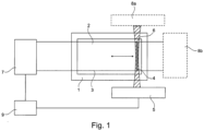
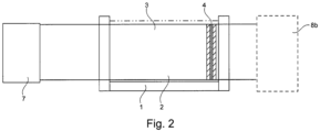
- FIG. 1 and 2 show a schematic representation of an arrangement for a device for optically processing an optically reactive material from above and from the side. This arrangement and this device are not covered by the patent claims.
- a working volume 2 is provided in a receptacle 1, which is at least partially filled by a starting material 3.
- the starting material can include one or more substances that can be solid, liquid or pasty.
- the starting material 3 is irradiated with light of a first wavelength and light of a second wavelength, which are irradiated in an overlapping manner in the working volume 2 to trigger an optically activated reaction in a layer partial volume 4.
- the light of the first wavelength is provided with the aid of a first light source 5, which in the embodiment shown is designed, for example, as a light section generator.
- a first light source 5 which in the embodiment shown is designed, for example, as a light section generator.
- an irradiation area 6 for the light of the first wavelength (light section) which is tailored in the embodiment shown, is moved piece by piece over the working volume 2, so that a layer-by-layer processing of the starting material 3 takes place.
- Layer partial volumes of the working volume 2 previously filled with the starting material 3 are irradiated one after the other, in particular layer partial volumes that do not overlap one another.
- the light of the second wavelength is projected using a projector 7 into the partial layer volume currently irradiated with the light of the first wavelength (projector or projection image).
- the projection plane or the projection volume of the projector 7 lies in the layer sub-volume which is currently being irradiated with the light of the first wavelength.
- At least one material property of the starting material 3 is changed in the currently irradiated layer-shaped partial volume, for example in such a way that the original starting material hardens.
- polymerization in the starting material 3 can be triggered due to the coincidence of the light of the two wavelengths.
- the three-dimensional shaping of the body is influenced and determined with the help of the projection of the projector 7 imaged into the respective layer volume.
- the device and the method allow adaptation to different volumes of the starting material 3. Furthermore, it allows optimization between resolution and speed of processing.
- the active state C When using ideal dual-color photoinitiators in the starting material 3, the active state C is only excited when both wavelengths ⁇ 1 and ⁇ 2 (first and second wavelength) are absorbed. For non-ideal photoinitiators, a transition from the intermediate state B to the active state C can also occur through absorption of the wavelength ⁇ 1 . As a consequence, photoinitiators are transferred to state C not only at the intersection of both wavelengths, but also along the entire light beam of wavelength ⁇ 1 . Since there is no return path from the active state C of the photoinitiator to the ground state A, when several desired target points are processed, a significant amount of initiators in the active state C accumulate in undesired areas.
- the device makes it possible to generate a sufficient initiator concentration in the active state C for the polymerization of the starting material in the overlapping area of the light beams, while at the same time minimizing the generated concentration of initiator molecules in the active state C along the light beam of the first wavelength ⁇ 1 . Furthermore, the device makes it possible to minimize the accumulation of photoinitiators in the active state C in undesirable areas of the volume caused by the light superposition for many successive target points.
- the photoinitiator can move to the intermediate state B and subsequently into the intermediate state B using light of the wavelength ⁇ 2 active state C.
- photoinitiators are converted to state C not only at the overlapping region of both wavelengths, but also along the entire light beam of wavelength ⁇ 2 . Since there is no return path from the active state C of the photoinitiator to the ground state A, when several desired target points are processed, a significant amount of initiators in the active state C accumulate in undesired areas.
- the device makes it possible to generate a sufficient initiator concentration in the active state C in the overlapping area of the light beams for the desired modification of the starting material 3, while at the same time minimizing the generated concentration of initiator molecules in the active state C along the light beam of wavelength ⁇ 2 . Furthermore, the device should make it possible to minimize the accumulation of photoinitiators in the active state C in undesirable areas of the volume, caused by the superimposition of light for many successive target points.
- the device and method can be combined with other techniques that limit undesirable curing due to accumulation of photoinitiators in the active state C.
- the oxygen concentration in the starting material can be adjusted in order to vary the threshold value at which the material hardens.
- the starting material 3 can be contained in a transparent vessel (receiving vessel 1) with at least two optically flat entry windows, which accommodates the starting material 3 with the added dual-color photoinitiator molecules or other optically active molecules and, if necessary, other additives such as co-initiators.
- the light source 5 designed as a light generator with imaging optics, generates a light section of wavelength ⁇ 1 which is irradiated into the working volume 2 through a window of the receiving vessel 1.
- the projector 7 with a light source of wavelength ⁇ 2 produces an image which is sharply imaged via a lens within the light section in the recording vessel 1.
- the refraction of the irradiated light of the second wavelength at the transitions between air and the receptacle 1 and between the receptacle 1 and the starting material 3 can result in a shift in the focal plane of the projected image (light second wavelength) compared to the optical image without recording vessel 1. If the working volume of the recording vessel 1 is large, the depth of field of the focused projector image may not be sufficient. In this context, a focus correction can then be carried out continuously during the movement of the light section through the working volume 2.
- the focus shift increases according to the above equation.
- the equation relates to a paraxial, optical beam path or larger distances between the projector 7 and the receptacle 1.
- the displacement can be compensated for by means of a motorized focus adjustment of the permanently mounted projector 7 or by means of a motorized positioning of the entire projector 7 relative to the light section position.
- the projector image can also enter the working volume 2 through the bottom or the lid of the receptacle 1, and the light section can be coupled perpendicular to this through one or more of the side windows.
- the light section generator 5 can generate the wavelength ⁇ 2 and the projector 7 generates the wavelength ⁇ 1.
- the projector 7 If the transition from the intermediate state B to the initial state A is to take place with light of wavelength ⁇ 3 , the projector 7 generates the wavelengths ⁇ 1 and ⁇ 3 or the wavelengths ⁇ 2 and ⁇ 3 , each complementary to the wavelength of the light section generator.
- the receiving vessel 1 can also be implemented as a flow system with automated supply and removal of the starting material 3 in order to process extended volumes.
- One or more light detectors 8a, 8b can be used to examine the processes during processing by measuring the transmitted light from the excitation of the light section and, if necessary, the projector 7.
- the light section generator 5 and possibly also the projector 7 can emit further light wavelengths that are different from the excitation wavelengths and only serve to observe the change in the material properties of the starting material 3, for example polymerization.
- a measurement of the emitted fluorescence from excited photoinitiators located in the starting material 3 can be provided.
- the intensity of the total transmitted or emitted light can be measured using a single photo detector and/or the spatially resolved intensity can be recorded using a camera.
- the detectors can selectively measure only certain light wavelengths from the projector 7, the light section generator 5 or the light-emitting, excited photoinitiators via filters or spectrographs in front.
- the evaluation of the total or spatially resolved intensities can control a control loop which influences the intensity of the light section generator, the intensity and image output of the projector, the timing of the exposure sequence and the displacement of the light section within the recording vessel 1.
- a control device 9 is provided, which according to Fig. 1 coupled to the light source 5 and the projector 7.
- a laser light source can be used as the light source 5, for example a pulsable single-mode diode laser (make: IBEAM SMART, Toptica Photonics AG, DE) with a wavelength of 375nm and an output power in continuous wave operation of max. 70mW, the laser beam diameter is 1.3mm (@ 1/e 2 ).
- An aspherical POWELL lens (fanning angle 30°, N-BK7, Edmund Optics GmbH, DE) is used to transform the laser beam into a diverging laser line.
- the usable height of the light cut in the area of the vessel due to the focusing is around 2cm.
- a suitably arranged rotating polygon mirror or a galvoscanner can be used as an alternative to the POWELL lens.
- a light source based on an LED (light-emitting diode) or a thermal light source instead of the laser.
- a DMD Digital Micromirror Device from Texas Instruments
- the projection optics were replaced by a projection lens with a 90mm focal length (Braun Ultralit 2.4 / 90, Braun Phototechnik GmbH, Germany), which generates a sharp image within the vessel.
- a filter glass GG475, Schott AG, Germany
- the projector 7 is controlled via an HDMI interface.
- a large cuvette made of optical glass (inner dimensions: 30mm x 30mm x 30mm, Hellma GmbH & Co. KG, DE) with transparent, flat entry windows can be used as the receiving vessel 1.
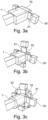
- Fig. 3a to 3c show schematic representations of an arrangement with a receiving vessel 1, in which the working volume 2 with the starting material 3 accommodated therein is arranged for optical processing.
- An arrangement of light sources 30 is provided.
- the light sources 30 (light generators for generating the light section 31), which serve to irradiate the light of the first wavelength (light section), are arranged adjacent to the receiving vessel 1, in particular on opposite sides.
- the arrangement of light sources 30 is rotatably arranged around the receptacle 1 with the working volume 2, which is shown schematically by arrows 32.
- Two or more of the light sources 30 can be used, which radiate into the working volume 2 from different sides of the receiving vessel 1 and generate the light section 31 by superimposing partial beams, i.e. irradiate the respective layer partial volume, into which the projection 33 then takes place.
- the light section 31 for the partial layer volume that has just been irradiated results from the summation of the individual irradiations from the light sources 30 at different irradiation angles.
- the individual irradiations can have a Gaussian or an adapted inhomogeneous intensity distribution instead of a homogeneous intensity distribution.
- Fig. 4 Two or more light sections 40 (layer partial volumes) are generated, which enter the receiving vessel 1 at an angle.
- One or more projections 41 from projectors (not shown for simplicity Fig. 4 ) produce sharp images within the individual light sections 40 in an oblique focal plane. This allows several layer partial volumes to be processed simultaneously.
- the receptacle 1 can be moved through the light section 31, 40, or the light section 31, 40 can be moved while the receptacle 1 is in a fixed position in order to process the working volume 2 continuously and finally completely by optically processing its layer partial volume one after the other.
- Fig.5 shows schematic representations for a further arrangement with a receiving vessel 1.
- Both a light section 50 of the first wavelength and a projector image 51 of the second wavelength are generated by means of a projection device 52 and then irradiated onto the receiving vessel 1.
- An arrangement of light reflection elements 53, in particular mirrors, ensures that the light section 50 is split off from a beam axis of the projection device 52 and the irradiation of the light section 50 transversely to the projection image 51 into the receiving vessel 1.
- the receptacle 1 can be moved to move the light beam through the working volume 2.
- the projector image 51 is imaged sharply within the light section 50 using variable focus optics.
- the receptacle 1 remains stationary and the light section 50 is moved by dividing a display element of the projection device 52, for example an LCD or a DMD display, into a central area 54, which generates the projector image 51, and in two areas 55 mounted to the side of it, which generate the light section 50.
- pixels of the display element are controlled by controlling the optical transmission or reflection of the display element in order to realize a lateral displacement of the light section 50.
- a central area of the display element is irradiated with the first wavelength and outer areas of the display element are irradiated with the second wavelength.
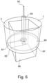
- Fig. 6 shows a schematic representation of a further arrangement for optically processing the starting material 3 in the receiving vessel 1. This arrangement is not covered by the patent claims.
- Fig. 7 shows a partial schematic representation of the arrangement Fig. 6 .
- a light section 60 is generated in a horizontal plane 61 by means of a laser beam 62, which enters from above into an immersion tube 63 that is optically transparent to the laser beam 62 and is deflected into the receiving vessel 1 with the starting material 3 by means of a motor-driven, rotating mirror 64.
- the light section 60 of the first wavelength is created by rotation.
- Projector light 66 of second wavelength is irradiated through a bottom 65 of the receptacle 1 in order to sharply image a projector image 67 in the horizontal plane 61 of the light section 60.
- the dip tube 63 is closed at the bottom.
- the motor-driven, rotating mirror 64 and the laser beam path 62 are separated from the starting material 3 in the receiving vessel 1.
- the dip tube 63 is moved up or down, whereby the horizontal plane of the light section 60 is moved up or down.
- the desired three-dimensional object is broken down into individual slice images with a defined grid spacing (slicing).
- the dual-color photoinitiators are excited from the basic state A into the active form C, which initiates the local polymerization of the starting material 3.
- the light excitation is shifted in a defined manner by moving the receiving vessel 1 and/or the light section and the projector 7 and the exposure of an adjacent or any other layer (other partial layer volume) is carried out.
- the translation of the projection arrangement or the recording vessel 1, which can be realized, for example, by means of suitable stepper motors, can optionally be below the waist diameter of the light section in order to produce an increase in resolution in the direction of movement.
- the volumetric method presented here generates the desired spatial object by polymerizing the starting material 3 within the working volume 2 in layers, but it leaves the basic structure of the starting material 3 unchanged. This is an advantage over processes that can only process the starting material in separate layers. Due to the layered exposure, the process is in principle faster than polymerizing the starting material point by point.
- the generation of the light cut by means of the light source 5 requires a coupling between the minimum waist diameter and the divergence of the beam, which leads to an expansion of the light beam towards the edge of the volume. This allows either a homogeneous, medium resolution to be generated along the light section or a higher resolution to be generated in the waist area with a greater drop-off towards the edges.
- each slice volume is only processed once and thus receives a defined energy dose. This effectively reduces the polymerization of unwanted areas when using non-ideal dual color photoinitiators.
- the targeted timing of the light pulses relative to one another and a suitable choice of the intensities of both wavelengths allows a greater discrimination between desired and undesired polymerization in the working volume 2. This can cause artifacts and reduce resolution degradation for non-ideal dual-color photoinitiators.
Landscapes
- Engineering & Computer Science (AREA)
- Chemical & Material Sciences (AREA)
- Materials Engineering (AREA)
- Manufacturing & Machinery (AREA)
- Physics & Mathematics (AREA)
- Optics & Photonics (AREA)
- Mechanical Engineering (AREA)
- Health & Medical Sciences (AREA)
- Toxicology (AREA)
- Microelectronics & Electronic Packaging (AREA)
- Heating, Cooling, Or Curing Plastics Or The Like In General (AREA)
Claims (15)
- Procédé de traitement d'un matériau optiquement réactif, avec:- Fourniture d'un matériau de base (3) qui est optiquement réactif et qui remplit un volume de travail (2) placé dans un récipient de réception (1); et- traitement optique du matériau de base (3) dans le volume de travail (2) par irradiation de la lumière d'une première longueur d'onde et de la lumière d'une seconde longueur d'onde différente de la première longueur d'onde, la lumière de la première longueur d'onde et la lumière de la seconde longueur d'onde étant fournie par un dispositif d'éclairage et l'usinage optique modifie au moins une caractéristique matérielle du matériau de base et l'usinage optique comprend:- L'irradiation d'une première partie de la couche du volume de travail (2) rempli avec la première longueur d'onde (2);- L'irradiation de la première partie du volume de travail (2) à la lumière de la seconde longueur d'onde, la lumière de la seconde longueur d'onde étant projetée dans le volume de travail (2) au moyen d'un dispositif de projection (7);- Irradier à l'aide de la première longueur d'onde un second volume de partie de couche du volume de travail rempli de la matière de départ (3) (2), différent du volume de la première partie de la couche;- L'irradiation de la seconde partie du volume de travail (2) à la lumière de la seconde longueur d'onde, la lumière de la seconde longueur d'onde étant projetée dans le volume de travail (2) à l'aide de l'appareil de projection (7); et- Répéter les étapes précédentes pour le traitement optique par couche du matériau de base (3) dans le volume de travail (2) jusqu'à un volume de travail (3) à traiter (3), qui couvre tout ou partie du volume de travail (2),caractérisé en ce que la lumière de première longueur d'onde est irradiée au moyen de plusieurs générateurs de lumière pour la production d'une coupe lumineuse, qui, de différents côtés du récipient d'enregistrement (1), pénètre dans le volume de travail (2) et génère, par superposition de faisceaux partiels, la section lumineuse (31) dans laquelle la projection a lieu (33).
- Procédé selon la revendication 1, dans lequel, à l'aide d'un dispositif de commande (9) relié à une ou plusieurs sources lumineuses (5) pour fournir la lumière première et la lumière de deuxième longueur d'onde, ainsi que le dispositif de projection (7), est déterminé si le volume de la première ou de la deuxième partie de la couche est irradié et le dispositif de projection (7) est commandé en fonction de la projection de la lumière de deuxième longueur d'onde dans la première ou la deuxième volume de partie de couche.
- Procédé selon la revendication 1 ou 2, dans lequel la lumière de la première longueur d'onde et la lumière de la seconde longueur d'onde sont simultanément irradiées simultanément dans la première ou la deuxième partie de la couche au moins pendant une période de chevauchement temporelle.
- Procédé selon au moins l'une des revendications précédentes, dans lequel les volumes de première et de deuxième partie de la couche dans le volume de travail (2) constituent des volumes adjacents de la matière première (3).
- Procédé selon la revendication 4, dans lequel les premier et deuxième volumes de pièces de couche sont formés selon l'une des configurations suivantes de volume partiel: se chevauchant sur le bord, se heurtant côte à côte et éloigné l'un de l'autre sur le bord.
- Procédé selon au moins l'une des revendications précédentes, dans lequel la matière de départ (3) dans le volume de travail (2) est éclairée par la lumière de la première longueur d'onde le long d'une première direction d'injection et la lumière de la seconde longueur d'onde le long d'un second sens d'injection qui traverse le premier sens d'injection.
- Procédé selon au moins l'une des revendications précédentes, dans lequel la lumière de la première longueur d'onde et/ou la lumière de la seconde longueur d'onde sont éclairées sous forme de lumière pulsée.
- Procédé selon au moins l'une des revendications précédentes, le matériau de base (3) étant traité au moyen de l'usinage optique selon au moins un procédé d'usinage du groupe suivant: Durcissement, durcissement, gélification et liquéfaction.
- Procédé selon au moins l'une des revendications précédentes, où, pour l'irradiation de la première partie de la couche et pour l'irradiation de la seconde partie de la couche avec la lumière de la première longueur d'onde, une zone de faisceau en couche d'une première source lumineuse fournissant la première longueur d'onde est déplacée par rapport au volume de travail (2) rempli avec le matériau de départ (3).
- Procédé selon au moins l'une des revendications précédentes, l'usinage optique du matériau de base (3) à l'aide d'un détecteur de lumière (8a); 8b) sont observés.
- Procédé selon au moins l'une des revendications précédentes, dans lequel une polymérisation polychrome multiphotons est déclenchée par l'usinage optique dans le matériau de base (3), ce qui entraîne la modification d'au moins une propriété matérielle du matériau de base (3).
- Procédé selon au moins l'une des revendications précédentes, dans lequel la lumière de première longueur d'onde est exposée d'abord dans le premier volume de partie de la couche, puis dans le second volume de partie de la couche avec une distribution essentiellement homogène par rapport à au moins l'un des paramètres lumineux suivants: Intensité lumineuse et couleur de la lumière.
- Procédé selon au moins l'une des revendications précédentes, où la lumière de la deuxième longueur d'onde est projetée d'abord sur le premier volume de partie de la couche, puis sur le deuxième volume de partie de la couche avec une distribution non homogène par rapport à au moins l'un des paramètres lumineux suivants: Intensité lumineuse et couleur de la lumière.
- Procédé selon au moins l'une des revendications précédentes, dans lequel, lors de l'irradiation de la première partie de la couche et/ou de l'irradiation de la seconde partie de la couche avec la lumière de la première longueur d'onde, un volume de parties de couche d'une épaisseur de couche n'excédant pas 1 mm est irradié.
- Dispositif d'usinage d'un matériau optiquement réactif, comportant:- d'un volume de travail (2) disposé dans un récipient d'accueil (1) et mis en place pour accueillir un matériau de départ (3) qui est optiquement réactif et qui remplit le volume de travail (2);- un dispositif d'éclairage conçu pour fournir la lumière d'une première longueur d'onde et la lumière d'une seconde longueur d'onde pour irradier le volume de travail (2) avec le matériau de base (3);- plusieurs générateurs de lumière pour la production d'une coupe lumineuse, conçus pour irradier la lumière de première longueur d'onde de différents côtés du récipient d'enregistrement (1) dans le volume de travail (2) et pour générer, par superposition de faisceaux partiels, la section lumineuse (31) dans laquelle la projection (33) a lieu; et- d'un dispositif de projection (7) conçu pour projeter la lumière de seconde longueur d'onde sur le volume de travail rempli de la matière de départ (3) (2) dans un volume de partie postée du volume de travail (2) et ne capter que le volume de la partie postée en tout ou en partie;- un dispositif de commande (9) relié aux générateurs de lumière multiples et au dispositif de projection (7);le dispositif d'éclairage et le dispositif de projection (7) continuent à être conçus pour traiter visuellement la matière première (3) dans le volume de travail (2) de la manière suivante, le dispositif de projection (7) étant commandé par le dispositif de commande (9):- L'irradiation d'une première partie de la couche du volume de travail (2) rempli avec la lumière de la première longueur d'onde au moyen de plusieurs générateurs de lumière;- Irradiation de la première partie de la couche du volume de travail (2) à la lumière de la seconde longueur d'onde, la lumière de seconde longueur d'onde étant projetée dans le volume de travail (2) à l'aide de celle d' dispositif de projection (7).- Irradier à l'aide de la première longueur d'onde un second volume de partie de couche du volume de travail rempli de la matière de départ (3) (2), différent du volume de la première partie de la couche;- L'irradiation de la seconde partie du volume de travail (2) à la lumière de la seconde longueur d'onde, la lumière de la seconde longueur d'onde étant projetée dans le volume de travail (2) à l'aide de l'appareil de projection (7); et- Répétez les étapes précédentes pour le traitement optique par couche du matériau de base (3) dans le volume de travail (2) jusqu'à un volume de travail (3) à traiter (3), qui couvre tout ou partie du volume de travail (2).
Priority Applications (1)
| Application Number | Priority Date | Filing Date | Title |
|---|---|---|---|
| EP24150751.6A EP4360853A1 (fr) | 2019-11-06 | 2020-11-06 | Procédé et appareil de traitement d'un matériau optiquement réactif |
Applications Claiming Priority (2)
| Application Number | Priority Date | Filing Date | Title |
|---|---|---|---|
| DE102019129868.7A DE102019129868A1 (de) | 2019-11-06 | 2019-11-06 | Verfahren und Vorrichtung zum Bearbeiten eines optisch reaktiven Materials |
| PCT/DE2020/100952 WO2021089090A1 (fr) | 2019-11-06 | 2020-11-06 | Procédé et appareil de traitement d'un matériau optiquement réactif |
Related Child Applications (1)
| Application Number | Title | Priority Date | Filing Date |
|---|---|---|---|
| EP24150751.6A Division EP4360853A1 (fr) | 2019-11-06 | 2020-11-06 | Procédé et appareil de traitement d'un matériau optiquement réactif |
Publications (3)
| Publication Number | Publication Date |
|---|---|
| EP4054827A1 EP4054827A1 (fr) | 2022-09-14 |
| EP4054827B1 true EP4054827B1 (fr) | 2024-01-10 |
| EP4054827C0 EP4054827C0 (fr) | 2024-01-10 |
Family
ID=73451979
Family Applications (2)
| Application Number | Title | Priority Date | Filing Date |
|---|---|---|---|
| EP20807657.0A Active EP4054827B1 (fr) | 2019-11-06 | 2020-11-06 | Procédé et appareil de traitement d'un matériau optiquement réactif |
| EP24150751.6A Pending EP4360853A1 (fr) | 2019-11-06 | 2020-11-06 | Procédé et appareil de traitement d'un matériau optiquement réactif |
Family Applications After (1)
| Application Number | Title | Priority Date | Filing Date |
|---|---|---|---|
| EP24150751.6A Pending EP4360853A1 (fr) | 2019-11-06 | 2020-11-06 | Procédé et appareil de traitement d'un matériau optiquement réactif |
Country Status (4)
| Country | Link |
|---|---|
| US (2) | US11999099B2 (fr) |
| EP (2) | EP4054827B1 (fr) |
| DE (1) | DE102019129868A1 (fr) |
| WO (1) | WO2021089090A1 (fr) |
Families Citing this family (12)
| Publication number | Priority date | Publication date | Assignee | Title |
|---|---|---|---|---|
| WO2023034402A1 (fr) | 2021-08-31 | 2023-03-09 | Quadratic 3D, Inc. | Photo-initiateurs, compositions photodurcissables et procédés de formation d'un objet dans un volume |
| EP4395977A1 (fr) | 2021-09-03 | 2024-07-10 | Readily3D SA | Procédé de correction analytique numérique d'une réactivité de matériau photosensible dans la fabrication additive |
| EP4257340A1 (fr) * | 2022-04-08 | 2023-10-11 | Photosynthetic B.V. | Procédé et appareil d'impression 3d couche par couche rapide à haute résolution |
| EP4738003A2 (fr) * | 2022-05-13 | 2026-05-06 | Quadratic 3D, Inc. | Compositions photodurcissables et procédés de formation d'un objet |
| DE102023104907A1 (de) | 2023-02-28 | 2024-08-29 | Xolo Gmbh | Verfahren zum Herstellen eines optischen Elements mittels Bearbeitens eines optisch reaktiven Materials und optisches Element |
| US20250073990A1 (en) * | 2023-09-01 | 2025-03-06 | Align Technology, Inc. | Scanning energy systems for additive manufacturing and associated methods |
| WO2025088201A1 (fr) | 2023-10-25 | 2025-05-01 | Miltenyi Biotec B.V. & Co. KG | Procédés d'amélioration d'impression 3d à l'aide d'une polymérisation bicolore |
| EP4663380A1 (fr) * | 2024-06-13 | 2025-12-17 | xolo GmbH | Procédé d'impression 3d volumétrique d'un objet tridimensionnel par photopolymérisation multicolore d'une résine photodurcissable |
| EP4663385A1 (fr) * | 2024-06-13 | 2025-12-17 | xolo GmbH | Appareil d'impression 3d volumétrique d'un objet tridimensionnel par photopolymérisation multicolore d'une résine photodurcissable |
| EP4663383A1 (fr) | 2024-06-13 | 2025-12-17 | xolo GmbH | Procédé d'impression volumétrique d'un objet tridimensionnel par photopolymérisation multicolore d'une résine photodurcissable |
| EP4725681A1 (fr) | 2024-10-10 | 2026-04-15 | Xolo GmbH | Procédé d'impression volumétrique d'un matériau de départ biocompatible |
| WO2026078149A1 (fr) | 2024-10-10 | 2026-04-16 | Xolo Gmbh | Procédé d'impression volumétrique d'un matériau de départ biocompatible |
Family Cites Families (11)
| Publication number | Priority date | Publication date | Assignee | Title |
|---|---|---|---|---|
| US160539A (en) | 1875-03-09 | Improvement in dishes of pottery-ware | ||
| US4041476A (en) | 1971-07-23 | 1977-08-09 | Wyn Kelly Swainson | Method, medium and apparatus for producing three-dimensional figure product |
| US4041576A (en) | 1972-12-20 | 1977-08-16 | Larson Carl T | Attachment device |
| US8404173B2 (en) * | 2006-11-17 | 2013-03-26 | Poof Technologies, Llc | Polymer object optical fabrication process |
| GB201501382D0 (en) * | 2015-01-28 | 2015-03-11 | Structo Pte Ltd | Additive manufacturing device with release mechanism |
| US11305482B2 (en) * | 2016-07-15 | 2022-04-19 | Purdue Research Foundation | Continuous and scalable 3D nanoprinting |
| US10875247B2 (en) * | 2016-07-15 | 2020-12-29 | Lawrence Livermore National Securitv. LLC | Multi-beam resin curing system and method for whole-volume additive manufacturing |
| US10647061B2 (en) * | 2017-05-12 | 2020-05-12 | Lawrence Livermore National Security, Llc | System and method for computed axial lithography (CAL) for 3D additive manufacturing |
| US10967578B2 (en) | 2017-07-11 | 2021-04-06 | Daniel S. Clark | 5D part growing machine with volumetric display technology |
| US20190160539A1 (en) * | 2017-11-30 | 2019-05-30 | Applied Materials, Inc. | Additive Manufacturing with Overlapping Light Beams |
| US11541599B2 (en) * | 2018-04-04 | 2023-01-03 | Ford Global Technologies, Llc | 3-D printing components using two-light sources to control location of solidification |
-
2019
- 2019-11-06 DE DE102019129868.7A patent/DE102019129868A1/de active Pending
-
2020
- 2020-11-06 EP EP20807657.0A patent/EP4054827B1/fr active Active
- 2020-11-06 US US17/755,624 patent/US11999099B2/en active Active
- 2020-11-06 WO PCT/DE2020/100952 patent/WO2021089090A1/fr not_active Ceased
- 2020-11-06 EP EP24150751.6A patent/EP4360853A1/fr active Pending
-
2024
- 2024-03-30 US US18/622,871 patent/US20240246286A1/en active Pending
Also Published As
| Publication number | Publication date |
|---|---|
| US20220410473A1 (en) | 2022-12-29 |
| US20240246286A1 (en) | 2024-07-25 |
| EP4360853A1 (fr) | 2024-05-01 |
| WO2021089090A1 (fr) | 2021-05-14 |
| DE102019129868A1 (de) | 2021-05-06 |
| EP4054827C0 (fr) | 2024-01-10 |
| EP4054827A1 (fr) | 2022-09-14 |
| US11999099B2 (en) | 2024-06-04 |
Similar Documents
| Publication | Publication Date | Title |
|---|---|---|
| EP4054827B1 (fr) | Procédé et appareil de traitement d'un matériau optiquement réactif | |
| EP4032688B1 (fr) | Procédé et dispositif de fabrication d'un objet tridimensionnel dans une matière de base optiquement réactive | |
| DE102011000835B4 (de) | Abtastmikroskop und Verfahren zur lichtmikroskopischen Abbildung eines Objektes | |
| EP3528029B1 (fr) | Microscope | |
| DE102012224005B4 (de) | Verfahren zur Herstellung einer homogenen Lichtverteilung | |
| EP2976669B1 (fr) | Procédé et dispositif optique pour manipuler et reproduire un échantillon microscopique | |
| DE102013215040B4 (de) | Kompakte Vorrichtung zur Herstellung eines dreidimensionalen Objekts durch Verfestigen eines fotohärtenden Materials | |
| EP3268212B1 (fr) | Procédé et système comprenant une source de rayonnement et un dispositif de correction d'une distribution d'intensité non-homogène d'un champ de rayonnement généré par la source de rayonnement | |
| AT518051B1 (de) | Vorrichtung und Verfahren zur Steigerung der Anhaftung einer Bauteilschicht an einem Trägerobjekt | |
| EP4476052B1 (fr) | Procédé de fabrication d'un élément optique par traitement d'un matériau optiquement actif et élément optique | |
| DE102016011801A1 (de) | Verfahren zum Kalibrieren einer Vorrichtung zum Herstellen eines dreidimensionalen Objekts und zum Durchführen des Verfahrens ausgebildete Vorrichtung | |
| EP3898181A1 (fr) | Lithographie 3d parallélisée par polymérisation induite par la lumière multicolore et multifaisceaux | |
| EP3111161B1 (fr) | Procédé et dispositif de détermination optique d'une distance | |
| DE202013103446U1 (de) | Kompakte Vorrichtung zur Herstellung eines dreidimensionalen Objekts durch Verfestigen eines fotohärtenden Materials | |
| DE102015221623A1 (de) | Belichteroptik und Vorrichtung zum Herstellen eines dreidimensionalen Objekts | |
| EP4163083A1 (fr) | Procédé et dispositif de fabrication additive par lithographie d'un composant tridimensionnel | |
| DE102014117613B4 (de) | Laseranordnung und Verfahren zur Untersuchung eines Objektes | |
| EP3888887A1 (fr) | Procédé et dispositif de fabrication additive par lithographie d'un composant tridimensionnel | |
| DE102023115813A1 (de) | Vorrichtung zum volumetrischen 3D-Drucken zur Herstellung eines dreidimensionalen Objekts | |
| DE102017102604B4 (de) | Verfahren zum Steuern eines Laserscanning-Mikroskops beim Abtasten einer Probe und Laserscanning-Mikroskop | |
| DE102020115869A1 (de) | Herstellung eines Objekts mittels Zwei-Photonen-Polymerisation | |
| DE102022203632A1 (de) | Bilderfassungsverfahren in der Lichtfeldmikroskopie und Lichtfeldmikroskop | |
| DE2307140A1 (de) | Bildverstaerker unter verwendung eines laserstrahlers | |
| WO2008125327A1 (fr) | Procédé et système de positionnement reproductible d'un objet cible dans le volume d'action d'un faisceau laser |
Legal Events
| Date | Code | Title | Description |
|---|---|---|---|
| STAA | Information on the status of an ep patent application or granted ep patent |
Free format text: STATUS: UNKNOWN |
|
| STAA | Information on the status of an ep patent application or granted ep patent |
Free format text: STATUS: THE INTERNATIONAL PUBLICATION HAS BEEN MADE |
|
| PUAI | Public reference made under article 153(3) epc to a published international application that has entered the european phase |
Free format text: ORIGINAL CODE: 0009012 |
|
| STAA | Information on the status of an ep patent application or granted ep patent |
Free format text: STATUS: REQUEST FOR EXAMINATION WAS MADE |
|
| 17P | Request for examination filed |
Effective date: 20220330 |
|
| AK | Designated contracting states |
Kind code of ref document: A1 Designated state(s): AL AT BE BG CH CY CZ DE DK EE ES FI FR GB GR HR HU IE IS IT LI LT LU LV MC MK MT NL NO PL PT RO RS SE SI SK SM TR |
|
| DAV | Request for validation of the european patent (deleted) | ||
| DAX | Request for extension of the european patent (deleted) | ||
| GRAP | Despatch of communication of intention to grant a patent |
Free format text: ORIGINAL CODE: EPIDOSNIGR1 |
|
| STAA | Information on the status of an ep patent application or granted ep patent |
Free format text: STATUS: GRANT OF PATENT IS INTENDED |
|
| GRAS | Grant fee paid |
Free format text: ORIGINAL CODE: EPIDOSNIGR3 |
|
| GRAA | (expected) grant |
Free format text: ORIGINAL CODE: 0009210 |
|
| STAA | Information on the status of an ep patent application or granted ep patent |
Free format text: STATUS: THE PATENT HAS BEEN GRANTED |
|
| INTG | Intention to grant announced |
Effective date: 20231123 |
|
| AK | Designated contracting states |
Kind code of ref document: B1 Designated state(s): AL AT BE BG CH CY CZ DE DK EE ES FI FR GB GR HR HU IE IS IT LI LT LU LV MC MK MT NL NO PL PT RO RS SE SI SK SM TR |
|
| REG | Reference to a national code |
Ref country code: GB Ref legal event code: FG4D Free format text: NOT ENGLISH |
|
| REG | Reference to a national code |
Ref country code: CH Ref legal event code: EP |
|
| REG | Reference to a national code |
Ref country code: DE Ref legal event code: R096 Ref document number: 502020006713 Country of ref document: DE |
|
| REG | Reference to a national code |
Ref country code: IE Ref legal event code: FG4D Free format text: LANGUAGE OF EP DOCUMENT: GERMAN |
|
| U01 | Request for unitary effect filed |
Effective date: 20240131 |
|
| U07 | Unitary effect registered |
Designated state(s): AT BE BG DE DK EE FI FR IT LT LU LV MT NL PT SE SI Effective date: 20240207 |
|
| PG25 | Lapsed in a contracting state [announced via postgrant information from national office to epo] |
Ref country code: IS Free format text: LAPSE BECAUSE OF FAILURE TO SUBMIT A TRANSLATION OF THE DESCRIPTION OR TO PAY THE FEE WITHIN THE PRESCRIBED TIME-LIMIT Effective date: 20240510 |
|
| PG25 | Lapsed in a contracting state [announced via postgrant information from national office to epo] |
Ref country code: GR Free format text: LAPSE BECAUSE OF FAILURE TO SUBMIT A TRANSLATION OF THE DESCRIPTION OR TO PAY THE FEE WITHIN THE PRESCRIBED TIME-LIMIT Effective date: 20240411 |
|
| PG25 | Lapsed in a contracting state [announced via postgrant information from national office to epo] |
Ref country code: RS Free format text: LAPSE BECAUSE OF FAILURE TO SUBMIT A TRANSLATION OF THE DESCRIPTION OR TO PAY THE FEE WITHIN THE PRESCRIBED TIME-LIMIT Effective date: 20240410 Ref country code: HR Free format text: LAPSE BECAUSE OF FAILURE TO SUBMIT A TRANSLATION OF THE DESCRIPTION OR TO PAY THE FEE WITHIN THE PRESCRIBED TIME-LIMIT Effective date: 20240110 |
|
| PG25 | Lapsed in a contracting state [announced via postgrant information from national office to epo] |
Ref country code: ES Free format text: LAPSE BECAUSE OF FAILURE TO SUBMIT A TRANSLATION OF THE DESCRIPTION OR TO PAY THE FEE WITHIN THE PRESCRIBED TIME-LIMIT Effective date: 20240110 |
|
| PG25 | Lapsed in a contracting state [announced via postgrant information from national office to epo] |
Ref country code: RS Free format text: LAPSE BECAUSE OF FAILURE TO SUBMIT A TRANSLATION OF THE DESCRIPTION OR TO PAY THE FEE WITHIN THE PRESCRIBED TIME-LIMIT Effective date: 20240410 Ref country code: NO Free format text: LAPSE BECAUSE OF FAILURE TO SUBMIT A TRANSLATION OF THE DESCRIPTION OR TO PAY THE FEE WITHIN THE PRESCRIBED TIME-LIMIT Effective date: 20240410 Ref country code: IS Free format text: LAPSE BECAUSE OF FAILURE TO SUBMIT A TRANSLATION OF THE DESCRIPTION OR TO PAY THE FEE WITHIN THE PRESCRIBED TIME-LIMIT Effective date: 20240510 Ref country code: HR Free format text: LAPSE BECAUSE OF FAILURE TO SUBMIT A TRANSLATION OF THE DESCRIPTION OR TO PAY THE FEE WITHIN THE PRESCRIBED TIME-LIMIT Effective date: 20240110 Ref country code: GR Free format text: LAPSE BECAUSE OF FAILURE TO SUBMIT A TRANSLATION OF THE DESCRIPTION OR TO PAY THE FEE WITHIN THE PRESCRIBED TIME-LIMIT Effective date: 20240411 Ref country code: ES Free format text: LAPSE BECAUSE OF FAILURE TO SUBMIT A TRANSLATION OF THE DESCRIPTION OR TO PAY THE FEE WITHIN THE PRESCRIBED TIME-LIMIT Effective date: 20240110 |
|
| PG25 | Lapsed in a contracting state [announced via postgrant information from national office to epo] |
Ref country code: PL Free format text: LAPSE BECAUSE OF FAILURE TO SUBMIT A TRANSLATION OF THE DESCRIPTION OR TO PAY THE FEE WITHIN THE PRESCRIBED TIME-LIMIT Effective date: 20240110 |
|
| PG25 | Lapsed in a contracting state [announced via postgrant information from national office to epo] |
Ref country code: PL Free format text: LAPSE BECAUSE OF FAILURE TO SUBMIT A TRANSLATION OF THE DESCRIPTION OR TO PAY THE FEE WITHIN THE PRESCRIBED TIME-LIMIT Effective date: 20240110 |
|
| REG | Reference to a national code |
Ref country code: DE Ref legal event code: R097 Ref document number: 502020006713 Country of ref document: DE |
|
| PG25 | Lapsed in a contracting state [announced via postgrant information from national office to epo] |
Ref country code: SM Free format text: LAPSE BECAUSE OF FAILURE TO SUBMIT A TRANSLATION OF THE DESCRIPTION OR TO PAY THE FEE WITHIN THE PRESCRIBED TIME-LIMIT Effective date: 20240110 |
|
| PG25 | Lapsed in a contracting state [announced via postgrant information from national office to epo] |
Ref country code: CZ Free format text: LAPSE BECAUSE OF FAILURE TO SUBMIT A TRANSLATION OF THE DESCRIPTION OR TO PAY THE FEE WITHIN THE PRESCRIBED TIME-LIMIT Effective date: 20240110 |
|
| PG25 | Lapsed in a contracting state [announced via postgrant information from national office to epo] |
Ref country code: SK Free format text: LAPSE BECAUSE OF FAILURE TO SUBMIT A TRANSLATION OF THE DESCRIPTION OR TO PAY THE FEE WITHIN THE PRESCRIBED TIME-LIMIT Effective date: 20240110 |
|
| PG25 | Lapsed in a contracting state [announced via postgrant information from national office to epo] |
Ref country code: SM Free format text: LAPSE BECAUSE OF FAILURE TO SUBMIT A TRANSLATION OF THE DESCRIPTION OR TO PAY THE FEE WITHIN THE PRESCRIBED TIME-LIMIT Effective date: 20240110 Ref country code: SK Free format text: LAPSE BECAUSE OF FAILURE TO SUBMIT A TRANSLATION OF THE DESCRIPTION OR TO PAY THE FEE WITHIN THE PRESCRIBED TIME-LIMIT Effective date: 20240110 Ref country code: RO Free format text: LAPSE BECAUSE OF FAILURE TO SUBMIT A TRANSLATION OF THE DESCRIPTION OR TO PAY THE FEE WITHIN THE PRESCRIBED TIME-LIMIT Effective date: 20240110 Ref country code: CZ Free format text: LAPSE BECAUSE OF FAILURE TO SUBMIT A TRANSLATION OF THE DESCRIPTION OR TO PAY THE FEE WITHIN THE PRESCRIBED TIME-LIMIT Effective date: 20240110 |
|
| PLBE | No opposition filed within time limit |
Free format text: ORIGINAL CODE: 0009261 |
|
| STAA | Information on the status of an ep patent application or granted ep patent |
Free format text: STATUS: NO OPPOSITION FILED WITHIN TIME LIMIT |
|
| 26N | No opposition filed |
Effective date: 20241011 |
|
| U20 | Renewal fee for the european patent with unitary effect paid |
Year of fee payment: 5 Effective date: 20241128 |
|
| REG | Reference to a national code |
Ref country code: CH Ref legal event code: PL |
|
| PG25 | Lapsed in a contracting state [announced via postgrant information from national office to epo] |
Ref country code: MC Free format text: LAPSE BECAUSE OF FAILURE TO SUBMIT A TRANSLATION OF THE DESCRIPTION OR TO PAY THE FEE WITHIN THE PRESCRIBED TIME-LIMIT Effective date: 20240110 |
|
| REG | Reference to a national code |
Ref country code: CH Ref legal event code: PL |
|
| GBPC | Gb: european patent ceased through non-payment of renewal fee |
Effective date: 20241106 |
|
| PG25 | Lapsed in a contracting state [announced via postgrant information from national office to epo] |
Ref country code: CH Free format text: LAPSE BECAUSE OF NON-PAYMENT OF DUE FEES Effective date: 20241130 |
|
| PG25 | Lapsed in a contracting state [announced via postgrant information from national office to epo] |
Ref country code: GB Free format text: LAPSE BECAUSE OF NON-PAYMENT OF DUE FEES Effective date: 20241106 |
|
| PG25 | Lapsed in a contracting state [announced via postgrant information from national office to epo] |
Ref country code: IE Free format text: LAPSE BECAUSE OF NON-PAYMENT OF DUE FEES Effective date: 20241106 |
|
| U20 | Renewal fee for the european patent with unitary effect paid |
Year of fee payment: 6 Effective date: 20251127 |
|
| PG25 | Lapsed in a contracting state [announced via postgrant information from national office to epo] |
Ref country code: HU Free format text: LAPSE BECAUSE OF FAILURE TO SUBMIT A TRANSLATION OF THE DESCRIPTION OR TO PAY THE FEE WITHIN THE PRESCRIBED TIME-LIMIT; INVALID AB INITIO Effective date: 20201106 |
|
| PG25 | Lapsed in a contracting state [announced via postgrant information from national office to epo] |
Ref country code: CY Free format text: LAPSE BECAUSE OF FAILURE TO SUBMIT A TRANSLATION OF THE DESCRIPTION OR TO PAY THE FEE WITHIN THE PRESCRIBED TIME-LIMIT; INVALID AB INITIO Effective date: 20201106 |