EP4054848B1 - Procédé et dispositif d'impression de surface latérale respective de corps creux - Google Patents
Procédé et dispositif d'impression de surface latérale respective de corps creux Download PDFInfo
- Publication number
- EP4054848B1 EP4054848B1 EP20781343.7A EP20781343A EP4054848B1 EP 4054848 B1 EP4054848 B1 EP 4054848B1 EP 20781343 A EP20781343 A EP 20781343A EP 4054848 B1 EP4054848 B1 EP 4054848B1
- Authority
- EP
- European Patent Office
- Prior art keywords
- hollow objects
- wheel
- printed
- printing
- mandrel
- Prior art date
- Legal status (The legal status is an assumption and is not a legal conclusion. Google has not performed a legal analysis and makes no representation as to the accuracy of the status listed.)
- Active
Links
Images

Classifications
-
- B—PERFORMING OPERATIONS; TRANSPORTING
- B41—PRINTING; LINING MACHINES; TYPEWRITERS; STAMPS
- B41F—PRINTING MACHINES OR PRESSES
- B41F17/00—Printing apparatus or machines of special types or for particular purposes, not otherwise provided for
- B41F17/08—Printing apparatus or machines of special types or for particular purposes, not otherwise provided for for printing on filamentary or elongated articles, or on articles with cylindrical surfaces
- B41F17/14—Printing apparatus or machines of special types or for particular purposes, not otherwise provided for for printing on filamentary or elongated articles, or on articles with cylindrical surfaces on articles of finite length
- B41F17/20—Printing apparatus or machines of special types or for particular purposes, not otherwise provided for for printing on filamentary or elongated articles, or on articles with cylindrical surfaces on articles of finite length on articles of uniform cross-section, e.g. pencils, rulers, resistors
- B41F17/22—Printing apparatus or machines of special types or for particular purposes, not otherwise provided for for printing on filamentary or elongated articles, or on articles with cylindrical surfaces on articles of finite length on articles of uniform cross-section, e.g. pencils, rulers, resistors by rolling contact
-
- B—PERFORMING OPERATIONS; TRANSPORTING
- B41—PRINTING; LINING MACHINES; TYPEWRITERS; STAMPS
- B41F—PRINTING MACHINES OR PRESSES
- B41F33/00—Indicating, counting, warning, control or safety devices
-
- B—PERFORMING OPERATIONS; TRANSPORTING
- B41—PRINTING; LINING MACHINES; TYPEWRITERS; STAMPS
- B41F—PRINTING MACHINES OR PRESSES
- B41F33/00—Indicating, counting, warning, control or safety devices
- B41F33/0009—Central control units
Definitions
- the invention relates to a method and a device for printing the respective lateral surface of hollow bodies according to claims 1 and 9.
- Such a device for printing or for the decoration of each particular a cylindrical lateral surface having hollow bodies is z. B. in connection with a production plant, which usually has several work stations, for the manufacture and further processing of such hollow bodies, the printing or the decoration of the hollow bodies being carried out by an industrially executed or at least executable printing process, which is why these hollow bodies can generally also be referred to as printed products.
- the hollow bodies to be printed are mass-produced with e.g. B. several hundred or even a few thousand pieces per minute, z. B. between 1,500 and 2,500 pieces per minute, particularly preferably between 1,800 and 2,200 pieces per minute.
- Such hollow bodies are z. B. made of metal, in particular steel or aluminum, or made of a plastic.
- Such hollow bodies made of plastic are z. B. in the form of thermoplastic moldings and z. B. as a cup for packaging z. B. of liquid or pasty food, especially dairy products or beverages.
- Another type of hollow bodies to be printed in an aforementioned device can be made of glass, preferably cylindrical containers or vessels, e.g. B. bottles or flasks.
- Beverage cans are preferably made of aluminum and are i. i.e. R. so-called two-piece cans, in which a circular bottom together with a preferably straight cylinder jacket each from a single workpiece, d. H. from a so-called slug or from a round, d. H. a circular disk, in a forming process, e.g. B. in a cold extrusion process or in a compression molding process, preferably by deep drawing, in particular by ironing, to a hollow body open on one side, d. H. are made into a so-called raw can and in a manufacturing step carried out at the end of production, a circular lid is placed on the cylinder jacket and connected airtight to the cylinder jacket by flanging.
- a forming process e.g. B. in a cold extrusion process or in a compression molding process, preferably by deep drawing, in particular by ironing
- An aerosol can also known as a spray can or spray can, is a metal can for spraying liquids.
- the filled liquid is under pressure, with z. B. propane, butane, dimethyl ether or mixtures thereof or compressed air or nitrogen is used.
- beverage cans are used for a filling volume of e.g. B. 330 ml or 500 ml.
- Beverage cans with a filling volume of 330 ml or 500 ml each have a diameter of mostly around 67 mm.
- the height of the 330 ml version is usually 115 mm, that of the 500 ml version is usually 168 mm.
- the lateral surface to be printed has a dimension of approx. 210 mm x 115 mm or approx. 210 mm x 168 mm. An adjustment of the printing devices in the production plant is therefore unavoidable.
- each of the inking units belonging to one of the printing units has an ink fountain for providing ink, with an ink fountain roller being provided in each ink fountain to receive the printing ink from the relevant ink fountain.
- An ink ductor is provided in each inking unit, with the ink ductor picking up printing ink from the respective ink fountain roller, with several iridescent ink distributor rollers and several ink transfer rollers each cooperating with at least one of the ink distributor rollers being provided in a roller train following the respective ink ductor in the inking unit concerned.
- a plate cylinder with at least one printing plate is provided for each inking unit, with only a single inking roller interacting with the respective plate cylinder for applying the printing ink.
- a device for decorating cans is known, with a plurality of inking stations and plate cylinder means, each of said plate cylinder means being separately driven by a main gearbox, said main gearbox being associated with pressure roller means so as to be completely independent of the roller drive means of each inking station.
- a continuous movement device for decorating cylindrical containers comprising: a decorating section and a transport section which conveys containers through a decoration zone in which decorations are applied to the containers, the transport section comprising: a carrier continuously moving on a rotates the beam axis, the beam having: a forward-facing side, a plurality of mandrel subassemblies mounted on the beam with equal angular spacing between adjacent subassemblies, each of the subassemblies being mounted to move along a single path relative to the beam axis disposed radially as a center, each of the subassemblies comprising: an elongate support arm extending along a single one of the paths, an axis extending forwardly from the arm that is generally parallel to the support axis, and a rail attached to and extending longitudinally from the arm; the axle includes a spindle portion for supporting a rotatable mandrel that conveys containers through the decorating zone
- a mandrel system for a can coating or decorating machine or the like comprising a ceramic sleeve member for supporting a workpiece and a sleeve support core member for supporting the ceramic sleeve member and at least two axially spaced bearing units carried by the sleeve support core member and/or the support core member.
- a decorator with a mandrel wheel, a segment wheel, a transfer disc and a transport chain is known, the mandrel wheel, the segment wheel, the transfer disc and the transport chain each having a motor and a decoder, a controller being provided, the controller being based on a the information received from the decoders adapts or sets the respective speed of the mandrel wheel, the segment wheel, the transfer disk and the transport chain.
- a device for printing on hollow bodies is known, with a segmented wheel and a device for sequentially feeding the hollow bodies to the circumference of the segmented wheel, this device having at least one feed wheel and one mandrel wheel, with the hollow body first having the feed wheel, then the mandrel wheel and then the segmented wheel is arranged, with several carriers being arranged on the circumference of the feed wheel and several holding devices being arranged on the circumference of the mandrel wheel, each for receiving a hollow body to be printed in cooperation with the segmented wheel, with the mandrel wheel and the feed wheel each having a separate drive from the segmented wheel have their own drive, the drive of the segment wheel and the drive of the mandrel wheel and the drive of the feed wheel being connected to one another by a common data bus.
- the invention has for its object to provide a method and a device for printing the respective lateral surface of hollow bodies with which a a format change, in particular a production change associated with a change in the height of the hollow body to be printed, can be carried out in a short changeover time.
- a production change involving a format change in particular a change in the height of the hollow bodies to be printed, can be carried out much more quickly on a generic production plant, since the conversion of the production plant to a production of hollow bodies with an opposite of previous production other height in the decorator no assembly work is to be carried out.
- the printing of the lateral surface of a hollow body with a z. B. multicolored print motif, ie at least one print image, is carried out in a preferred embodiment in a letterpress process.
- Alternative or additional printing processes are e.g. B. a screen printing process or an offset printing process or a formless digital printing process.
- the invention is described by way of example in connection with an indirect letterpress process in which printing ink is first applied to a printing blanket and only from there to the lateral surface of a hollow body.
- a printing plate is arranged as a printing form on a lateral surface of a plate cylinder, which is why this cylinder is sometimes also referred to as a plate cylinder, especially if the printing plate z.
- printing forme cylinder is arranged on a mounted on the cylinder sleeve sleeve or is.
- the more general term “printing forme cylinder” used below should in principle include both embodiments, ie the classic design as a plate cylinder and the design as a “cliché cylinder”.
- the printing block ready for the printing process is a printing form with a printing relief, this print relief reproduces the print image intended for the printing process of the indirect letterpress process in a non-reflected manner, in contrast to the classic, i.e. direct letterpress process, whereby in trouble-free printing operation only the print relief is involved in the transfer of the printing ink supplied to the plate cylinder by the inking unit onto at least one printing blanket that interacts with this plate cylinder is.
- the printing form or the printing plate to be mounted on a plate cylinder has, for. B. a plate-shaped preferably flexible support finite length z. B. from a sheet steel, wherein a particularly flexible pressure body is arranged on this carrier. At least the opposite ends of the carrier in the circumferential direction of the plate cylinder can e.g. B. according to the curvature of the lateral surface of the plate cylinder may be pre-bent or angled to facilitate assembly of the printing forme, d. H. to allow here in particular the printing plate on the plate cylinder.
- the carrier of the printing form or the printing plate has a thickness in the range of z. 0.2mm to 0.3mm.
- the pressure plate has, including its carrier, a total thickness in the range of z. B.
- the pressure body is z. B. formed from a plastic.
- the printing body is used to produce the printing block that can be used for the printing process, e.g. B. exposed with a negative film depicting the print image, with unexposed areas then being removed from the print body, e.g. B. be removed by washing or by means of a laser.
- a device for printing or decorating hollow bodies each having a preferably cylindrical lateral surface is also referred to as a decorator and preferably has several, e.g. B. eight or ten or even more printing units, which are also called printing stations, wherein at least one of these printing units, in the preferred embodiment all of these printing units each have an inking unit and a rotatable printing forme cylinder, in particular a printing forme cylinder designed as a plate cylinder.
- the printing works or Printing stations optionally stored in a frame together with the printing forme cylinders in this device and can be used in the same printing process to form a multicolored print motif on the same hollow body according to the number of printing units or printing forme cylinders involved.
- the storage of the printing forme cylinder or plate cylinder is preferably carried out at both ends, but it can also be designed as a cantilever mounting, in which the printing forme cylinder or plate cylinder in question is only on one of its end faces, e.g. B. is mounted on a preferably conical pin.
- the printing forme cylinder or plate cylinder in question is only on one of its end faces, e.g. B. is mounted on a preferably conical pin.
- only a single printing plate is arranged on the outer surface of each printing form cylinder, with the carrier of the printing plate enclosing the circumference of the relevant printing form cylinder completely or at least for the most part, in particular more than 80%.
- a length of the printing body of the printing block directed in the peripheral direction of the relevant printing forme cylinder is preferably shorter than the peripheral length of the relevant printing forme cylinder.
- the printing form or the printing cliché is or at least can be arranged magnetically on the lateral surface of each printing form cylinder by means of its carrier, ie the printing form or the printing cliché is preferably held there magnetically, ie by means of a magnetic holding force.
- the device for printing or for decorating hollow bodies each having a preferably cylindrical lateral surface, at least one of the printing units or several of these printing units are each configured as a printing unit that prints without a printing form in a digital printing process, with such a printing unit in particular has at least one inkjet print head or a laser.
- a register-accurate arrangement of the printing forme or the printing plate on the lateral surface of the relevant printing forme cylinder or plate cylinder are preferably several z.
- adjustable dowel pins are provided, which engage in corresponding recesses formed on the printing forme or on the printing plate and the printing forme or the printing plate as a result when it is arranged on the lateral surface of the printing forme cylinder or plate cylinder in question there give a defined position.
- each printing form cylinder or plate cylinder has a diameter in the range between 100 mm and 150 mm, in particular between 120 mm and 130 mm, with an axial length of the printing form cylinder or plate cylinder in question z. B. between 200 mm and 250 mm, in particular between 200 mm and 220 mm.
- the to be arranged on the lateral surface of the printing forme cylinder or plate cylinder in question has a width directed in the axial direction of the plate cylinder in question in the range of z. B. 100mm to 200mm.
- Each of the z. B. designed as a plate cylinder printing forme cylinder transfers with its printing forme or with its printing block in each case a specific ink on a blanket.
- the printing inks used are usually pre-mixed, in particular order-specific special inks, which are used e.g. B. are matched in terms of their respective printability in a special way on the material of the hollow body to be printed, depending on whether a surface z. B. aluminum, a tinplate or a plastic is printed.
- order-specific special colors also usually differ in their respective shade.
- a device which transfers printing ink from the printing form or the printing block to the lateral surface of the hollow body in question.
- This ink-transferring device is preferably designed as a segmented wheel rotating about a horizontal axis in particular, wherein on the periphery of this segmented wheel, ie along its circumference, preferably several, e. B. eight, ten, twelve or even more blankets are arranged or at least can be arranged.
- the ink-transferring device can also be designed as a decoration drum or as a printing blanket cylinder or as a transfer cylinder, which can each be rotated about an axis of rotation, at least during printing.
- the arrangement of the printing blankets on the circumference of the segmented wheel takes place e.g. B. in that the printing blankets on the circumference of the segmented wheel each z. B. are attached by a material connection, preferably by gluing.
- the preferably several printing forme cylinders or plate cylinders are or at least can be placed radially on the printing blankets arranged on the circumference of the relevant segmented wheel.
- cylindrical outer surface having hollow bodies - ie a decorator - is arranged along the circumference of the segmented wheel one behind the other a larger number of printing blankets than radially employed or at least adjustable printing forme cylinders or plate cylinders are provided on the segmented wheel.
- the preferably carousel-like ink-transferring device in particular the segmented wheel has a diameter of z. B. 1400 mm to 1600 mm, preferably about 1520 mm to 1525 mm, and has at z. B. eight associated printing form cylinders or plate cylinders on its circumference in a row z. B. twelve printing blankets.
- the surface of each printing block is preferably designed with a greater hardness than the hardness of the respective surface of the printing blankets.
- the surface of the printing blankets is preferably flat, ie without profiling educated.
- the respective printing formes of these printing forme cylinders or the respective printing blocks of these plate cylinders roll on the printing blankets moved with the segmented wheel, with the printing blocks press at least their printing relief into the respective printing blanket or at least press it on.
- An intensity of the indentation is z. B. before or at the beginning of a printing process z. B. by means of a remote control by adjusting a pressure force exerted by the relevant printing forme cylinder or plate cylinder on the relevant printing blanket of the segmented wheel or is set in this way.
- the hollow bodies to be printed are each attached to at least one of the z. B.
- z. B. designed as a segment wheel ink-transferring device transported in the respective printing area of at least one of these printing units, which z. B. is the case when the printed matter in question in a direct printing process, z. B. prints in an inkjet printing process.
- the segmented wheel also rotates around a preferably horizontal axis feed wheel or mandrel wheel has concentrically to its circumference preferably equidistant distribution several, z. B. 24 or 36 holding devices - in short: holder - z. B. each in the form of a mandrel projecting from a front side of the mandrel wheel or a spindle, wherein one of the hollow bodies to be printed is held or at least can be held by each holder.
- a transport device designed as a mandrel wheel is sometimes also referred to as a turntable with spindles.
- a mandrel wheel is z. B. in the EP 1 165 318 A1 described.
- each mandrel is referred to as a mandrel for short.
- a longitudinal axis of each mandrel is directed parallel to the axis of the mandrel wheel.
- each z. B. designed as a two-piece can to be printed hollow bodies, each of these hollow bodies z. B. by means of a conveyor, z. B. a belt conveyor and / or a conveyor wheel to which z. B. trained as a mandrel wheel transport device and there at a transfer station z. B.
- Each mandrel can be rotated almost smoothly around its respective longitudinal axis.
- Each of the mandrels is driven by a drive means cooperating with the respective mandrel, e.g. B.
- Friction is set to a specific peripheral speed or is at least adjustable such that each hollow body to be printed held by a mandrel is arranged to rotate or at least rotatable in addition to the rotation of the mandrel wheel by a rotation performed or at least executable independently by the mandrel.
- the hollow body to be printed is placed on one of the mandrels of the mandrel wheel preferably during a standstill phase of the relevant mandrel, with the relevant mandrel not rotating about its own longitudinal axis during its standstill phase.
- the occupancy of each mandrel with a hollow body to be printed is preferably checked, e.g. B. contactless with a sensor. If there is no occupancy of a mandrel with a hollow body to be printed, the mandrel wheel z. B. moved in such a way that contact of the relevant free mandrel and optionally a few other mandrels is reliably avoided with a printing blanket of the segmented wheel.
- Two-piece cans to be printed are z. B. to the mandrel wheel in a processing station upstream of the mandrel wheel, e.g. B. deep-drawn from a blank. In a further processing station, the edge of each two-part can is trimmed at its open end.
- Each two-part can is processed in further processing stations, e.g. B. washed, especially its interior washed out, if necessary, the inner wall and the bottom of the two-piece can in question are also painted.
- At least the outer surface of each two-piece can is z. B. primed, especially with a white primer. After printing its lateral surface, each two-piece can is removed from its respective holder, e.g. B. on the mandrel z.
- B. removed by compressed air or by a preferably switchable magnet and fed to at least one processing station downstream of the mandrel wheel, e.g. B. a painting station for painting the outer surface of each printed two-piece can and / or an edge processing station.
- the printed two-part cans pass through a dryer, e.g. B. a hot air dryer to cure the at least one applied to their respective lateral surface printing ink.
- the printing process for printing in particular the respective lateral surface of z. B. held on the mandrel wheel hollow bodies, especially two-part cans begins with the fact that all the inks required for the print image to be printed on the respective lateral surface of the hollow body z. B. from the respective printing block z. B. applied to the segmented wheel employed plate cylinder on the same of one of the arranged on the periphery of the segmented wheel printing blankets.
- the printing inks required for the print image to be printed on the respective lateral surface of the hollow body are therefore collected on the respective printing block.
- the printing blanket in question which has been inked with all the necessary printing inks in this way, then transfers these printing inks simultaneously during a single rotation of the hollow body to be printed, which is held on one of the mandrels of the mandrel wheel, about its longitudinal axis to the lateral surface of this hollow body in a physical contact between the printing blanket and the lateral surface of the hollow body to be printed.
- the z. B. held by one of the mandrels of the mandrel wheel to be printed hollow body with an equal peripheral speed as the relevant z. B. at the periphery of the segmented wheel arranged printing blanket.
- the respective circumferential speeds of the hollow body and the blanket or segmented wheel are therefore synchronized with one another, with the z.
- the segmented wheel is accelerated accordingly, the peripheral speed of the mandrel in question of the mandrel wheel preferably starting from a first point of contact of the hollow body to be printed with the printing blanket in question during the unrolling of its lateral surface over a distance z. B. is synchronized from the first 50 mm of the circumferential length of the blanket with the peripheral speed of the segmented wheel.
- the segmented wheel carrying the blanket in question gives the z. B.
- the peripheral speed of the printing forme-carrying printing forme cylinder or of the plate cylinder carrying the printing plate is or is preferably a function of the peripheral speed z.
- at least the mandrel wheel and the segmented wheel are each driven in rotation by their own drive and their respective rotational behavior is controlled or regulated by a control unit.
- FIG. 1 shows a simplified schematic representation and example of a device for printing on or decorating hollow bodies 01, e.g. B. two-piece cans 01, these hollow body 01 with a conveyor sequentially z. g. as a rotating or at least rotatable feed wheel, in particular as a mandrel wheel 02, and held there individually on this transport device on a holder designed as a mandrel or as a spindle.
- a conveyor sequentially z. g. as a rotating or at least rotatable feed wheel, in particular as a mandrel wheel 02, and held there individually on this transport device on a holder designed as a mandrel or as a spindle.
- this transport device is preferably embodied as a mandrel wheel 02 that rotates or is at least rotatable about an axis of rotation 41.
- An ink-transferring device e.g. g. a segmented wheel 03 that rotates or is at least rotatable about an axis of rotation 34, along the circumference of which a plurality of printing blankets 33 are arranged one behind the other.
- a plurality of printing forme cylinders 04, in particular plate cylinders 04, which are or at least can be thrown radially onto this segmented wheel 03 are provided along its circumferential line, with these printing forme cylinders 04 or
- Each plate cylinder 04 has a printing forme, in particular a printing block, with this printing block being designed in particular to carry out a letterpress process.
- Each of the printing forme cylinders 04 or plate cylinders 04 is supplied with a specific printing ink by means of an inking unit 06 for inking its printing forme or printing block. It is assumed below, for example, that the printing forme cylinders 04 are each embodied as a plate cylinder 04 carrying at least one printing block.
- each inking unit 06 preferably being designed as a short inking unit and e.g. B. has only a single inking roller 07 and an anilox roller 08 ( 2 ).
- On the circumference of the segmented wheel 03 several, e.g. B. 12 printing blankets 33 are arranged, with a mandrel wheel 02 having 24 holding devices being set to rotate at half the speed compared to a segmented wheel 03 with 12 segments 32.
- Each of the printing blankets 33 arranged on a segment 32 on the circumference of the segmented wheel 03 is z. B.
- the segmented wheel 03 preferably has a base body, the plurality of z. B. twelve segments 32 along the circumference of the base body z. B. each at a joint 31 in particular each spaced apart from each other or at least can be arranged. In the preferred embodiment, the segmented wheel 03 is therefore not designed in one piece, with segments 32 already formed on it. B. by releasing at least one connecting element.
- each of the to be arranged on the segmented wheel 03 Printing blankets 33 each on a preferably flat tabular metal support with a material thickness of z. B. 0.2 mm cohesively, applied in particular by gluing.
- the respective, preferably magnetizable, metal carrier, together with the printing blanket 33 arranged on it, is then mounted on one of the segments 32 on the circumference of the segmented wheel 03, e.g. B. by at least one holding magnet provided there on the circumference for each printing blanket 33 or its carrier, in particular arranged in the correct position.
- the respective metal carrier In order to support the correct positioning of the respective metal carrier on the relevant segment 32 on the circumference of the segmented wheel 03, e.g. B.
- an acute-angled suspension leg 38 is provided, with this suspension leg 38 being arranged on one of the segments 32 on the circumference of the segmented wheel 03 in one on the circumference of this segmented wheel 03 parallel to its axis of rotation 34 directed z.
- B. designed as a groove engages recess 36 and comes into contact with a leading edge 39 of the relevant recess 36 in the direction of rotation of the segmented wheel 03, in particular in a form-fitting manner.
- the printing blankets 33 are each preferably designed as a rubber blanket.
- the direction of rotation of the segmented wheel 03 during the printing process is in the 1 indicated by an arrow indicating the direction of rotation.
- the hollow bodies 01 which are guided by the mandrel wheel 02 rotating about the axis of rotation 41 on a mandrel to the segmented wheel 03, are moved individually and one after the other for a short time, i.e. usually for a single revolution of the hollow body 01 to be printed, to the current one in question by a primarily radial movement of the mandrel in question printing blanket 33 pressed, which is in the 1 is indicated by a double arrow indicating the movement of the relevant hollow body 01 to be printed.
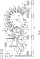
- FIG. 2 shows a simplified and schematic embodiment of the device for printing hollow bodies 01, in which several hollow bodies 01 are sequentially conveyed with a conveyor device 74 in the transport direction indicated by an arrow a feed wheel 76 and from there to the mandrel wheel 02 and then to the segmented wheel 03.
- the conveyor device 74 has at least two elements guiding the hollow bodies 01 at a distance from one another. B. each lead the head and the bottom of the hollow body 01 in question. If there is a change in the height of the hollow body 01 in question, it is necessary to adapt the distance between the elements guiding the head and the bottom of the hollow body 01 in question to the current height of the hollow body 01 in question.
- the hollow bodies 01 to be fed into the printing process must not be arranged too loosely or too tightly between the elements of the conveyor system 74 that guide these hollow bodies 01 at the top and bottom, since otherwise a smooth and/or trouble-free transport of these hollow bodies 01 is not guaranteed, particularly at higher speeds.
- the conveyor wheel 76 which rotates or can at least be rotated about an axis of rotation 43, and the mandrel wheel 02, which rotates or can at least be rotated about its axis of rotation 41, form a device for sequentially feeding the hollow bodies 01 to the circumference of the segmented wheel 03.
- B. eight or ten drivers and on the circumference of the mandrel wheel 02 are several, z. B. 24 or 36 holding devices are each arranged to accommodate one hollow body 01 to be printed in cooperation with the segmented wheel 03.
- the drivers of the feed wheel 76 are z. B. formed by recesses on its periphery, each recess always receive exactly a single hollow body 01 at a certain point in time and can convey during the rotation of the conveyor wheel 76.
- the inclusion of a hollow body 01 in the relevant recess of the conveyor wheel 76 is z. B. supported by an air blast device 98 arranged in the periphery of the feed wheel 76, with at least one air blast being triggered by the air blast device 98, which pushes the hollow body 01 in question, in the direction of the feed wheel 76, depending on an angular position of the feed wheel 76.
- the feed wheel 76 is formed in an advantageous embodiment as a star wheel with a plurality of drivers each in the form of pointed teeth, with a space between adjacent Prongs recorded hollow body 01 is conveyed during the rotation of the star wheel.
- the mandrel wheel 02 and the feed wheel 76 each have a separate from the drive 13 of the segmented wheel 03 each z. B. designed as a motor drive 77; 78, the drive 13 of the segmented wheel 03 and the drive 77 of the mandrel wheel 02 and the drive 78 of the feed wheel 76 being connected to one another in terms of data technology by a common data bus 79.
- This drives 13; 77; 78 connecting preferably digital data bus 79 is z. B. formed in a ring topology or in a star topology. It controls a connected to the data bus 79, z. B.
- control unit 82 configured as a central machine controller by means of control data transported via the common data bus 79, at least both the drive 78 of the feed wheel 76 and the drive 77 of the mandrel wheel 02, preferably also the drive 13 of the segmented wheel 03 and others, in particular all of them on this data bus 79 connected drives.
- the drive 77 of the mandrel wheel 02 or the drive 13 of the segment wheel 03 are each defined as the master, so that the other drives are each aligned as slaves in their respective rotational behavior according to the previously defined master.
- this control data thus e.g. B. the function of a virtual leading axis.
- the control data transported via the virtual master axis are a command variable for the axes to be coordinated of the drives 13 connected to this data bus 79; 77; 78. From the control data forming a position value of the virtual master axis, ie the master value of the virtual master axis, for each through the drives 13; 77; 78 a position setpoint is calculated for the given following axis.
- At least the drive 77 of the mandrel wheel 02 and the drive 13 of the segmented wheel 03 and, if applicable, also the drive 78 of the feed wheel 76 are each designed as an electrical direct motor drive whose position is controlled by the control unit 82 and/or whose respective speed is set.
- the drive 13 of the segment wheel 03 is z. B. designed as a torque motor.
- at least the respective drives 13; 77; 78 of the feed wheel 76, mandrel wheel 02 and segment wheel 03 are each assigned their own drive controller 83 connected to the data bus 79 and their own power unit 84.
- the hollow bodies 01 e.g. by means of vacuum suction, are successively placed one after the other on one of the mandrels of the mandrel wheel 02 and then held by the mandrel in question respective longitudinal axis rotatable and in particular set or at least adjustable to a specific peripheral speed.
- at least one hollow body 01 preferably several hollow bodies 01 each held on one of the mandrels of the mandrel wheel 02, are each held on to one of the mandrels of the mandrel wheel 02 before being printed on using at least one of the printing blankets 33 arranged on the circumference of the segmented wheel 03, e.g. B.
- a preferably endlessly revolving acceleration belt 86 arranged in particular in the periphery of the mandrel wheel 02 and in physical contact with these hollow bodies 01, ie rotated by friction and adjusted to the peripheral speed required for the printing process.
- This acceleration belt 86 preferably has its own drive 13; 77; 78 of the feed wheel 76, the mandrel wheel 02 and / or the segment wheel 03 separate, but z. B. also connected to the data bus 79 drive 87, wherein the peripheral speed of the acceleration belt 86 is optionally adjustable.
- the peripheral speed of the acceleration belt 86 is thus z. B. individually adjustable and / or changeable for each hollow body 01 depending on the requirements of the printing process.
- the drive 87 of the acceleration belt 86 is z. B. assigned its own drive controller 83 and its own power unit 84.
- At least one processing station arranged in the periphery of the mandrel wheel 02 after the printing of the hollow body 01 is z. B. as a painting device 88 for painting the outer lateral surface of each printed hollow body 01 and/or, in particular in the case of two-piece cans 01, as an edge processing station.
- the processing station embodied as painting device 88 has at least one paint application roller 89 that is or at least can be placed on the lateral surface of at least one of the printed hollow bodies 01 held by mandrel wheel 02.
- the paint-applying surface of the relevant paint applicator roller 89 is matched to the respective format of the hollow body 01 to be painted.
- the axial extension of this surface running parallel to the axis of rotation of the paint application roller 89 in question should always be tailored to the respective format of the hollow body 01 to be painted and thus to its height.
- the axial extent of the paint-applying surface of this paint application roller 89, which runs parallel to the axis of rotation of the relevant paint application roller 89 must be positioned axially congruently with the height of this hollow body 01, depending on the current height of the hollow body 01 to be painted.
- Lacquer application roller 89 of lacquering unit 88 is preferably driven in rotation by its own drive 91, with a hollow body 01 held on mandrel wheel 02 being rotated by means of friction in Rotation offset and z. B. is set to a specific peripheral speed depending on the requirements of the painting process.
- the peripheral speed of the hollow body 01 by the drive 91 of the paint applicator roller 89 is independent of the drives 13; 77; 78 of the feed wheel 76, the mandrel wheel 02 and/or the segment wheel 03 is set or at least adjustable.
- the drive 91 of the paint applicator roller 89 is also assigned its own drive controller 83 and its own power unit 84 .
- the Paint applicator roller 89 of the painting device 88 has a mechanical friction brake, with a friction body 96 of this friction brake being arranged to brake at least one rotating hollow body 01 held on one of the holding devices of the mandrel wheel 02 by friction.
- the friction body 96 of the friction brake is moved relative to the rotating hollow body 01 held on one of the holding devices of the mandrel wheel 02, the movement of the friction body 96 of the friction brake having a tangential speed component to the outer surface of the hollow body 01.
- the friction body 96 of the friction brake is embodied as a revolving braking belt 96 driven by a drive roller 97 and acting on at least one of the holding devices, with the braking belt 96 acting on at least one rotating hollow body 01 held on one of the holding devices of the mandrel wheel 02 at least one of the holding devices of the mandrel wheel 02 is arranged to brake by friction.
- the braking belt 96 is preferably arranged to rotate on deflection rollers and is driven by the drive roller 97 with regard to its revolving movement.
- At least one rotating hollow body 01 held on the mandrel wheel 02 which is braked by friction from the friction body 96 or the braking belt 96, has reached a peripheral speed required for further transport as a result of this braking process after it has been printed on by at least one of the printing blankets 33 arranged on the circumference of the segmented wheel 03 set.
- This peripheral speed of the hollow body 01 is independent of the drives 13; 77; 78; 91 of the feed wheel 76 and/or the mandrel wheel 02 and/or the segmented wheel 03 and/or the paint application roller 89 of the painting unit 88 is adjusted or at least adjustable. the z. B.
- a braking band 96 friction body 96 of the friction brake enables an optimal braking process of the rotating hollow bodies 01 that are about to be passed on.
- This braking process is particularly advantageous or necessary at high rotational speeds of the mandrels in connection with mandrels for large-volume hollow bodies 01 with a high mass moment of inertia.
- the braking process increases operational reliability when the hollow body 01 is transferred from the mandrel wheel 02 to a further transport device significantly increased.
- a z. g. as a rotatable transfer disc 92 is provided for receiving the hollow bodies 01 held on the mandrel wheel 02, printed by means of at least one of the printing blankets 33 arranged on the circumference of the segmented wheel 03 and possibly painted on their lateral surface.
- a peripheral speed of the transfer disk 92 is either by its own rotary drive 73 or z. B. depending on the rotation of the conveyor wheel 76 z. B. with the drive 78 of this conveyor wheel 76 z. B. adjusted or at least adjustable by means of a belt drive. In the latter case, the drive 73 of the transfer disk 92 z. B. with the drive 78 of the conveyor wheel 76 z. B.
- the shaft of the transfer disc 92 is of its own, e.g. H. from the other drives 13; 77; 78; 87; 91 separate drive 73 driven in rotation, this drive 73 is preferably designed as a motor.
- this drive 73 is preferably designed as a motor.
- the transfer disc 92 and the mandrel wheel 02 are positioned in a lateral, i. H. offset in the axial direction to one another and thus arranged to rotate in two different vertical planes that are parallel to one another. If e.g. If, for example, the height of the printed and/or painted hollow body 01 changes due to a change in production, this lateral offset of the transfer disk 92 and the mandrel wheel 02 must also be adjusted.
- a further conveyor device 93 for conveying printed and/or painted hollow bodies 01, e.g. B. provided in a dryer, said conveyor 93 z. B. as a revolving transport chain 93 with several, z. B. twenty or more pick-ups, each designed to receive one of the hollow bodies 01 to be conveyed and preferably has its own drive 94, in particular a chain drive, with this drive 94 preferably being at least connected to the drives 13; 77; 78 of Segment wheel 03, mandrel wheel 02 and feed wheel 76 connecting data bus 79 is connected.
- the drive 94 of this conveyor 93 is z. B.
- At least the drives 13; 77; 78 of segment wheel 03, mandrel wheel 02 and feed wheel 76 are each designed as individual drives and are connected to one another via a common data bus 79.
- further individual drives connected to the common data bus 79 are provided in the device for printing on hollow bodies 01, e.g. B. the drive 87 for the acceleration belt 86 and/or the drive 91 for the paint applicator roller 89 of the painting device 88 and/or the possibly own drive 73 for the transfer disc 92 and/or the drive 94 for the transport chain 93.
- All these drives 13; 73; 77; 78; 87; 91; 94 are connected to the common data bus 79, z. B. as a central machine control unit 82 is controlled by means of control data transported via this common data bus 79, said control data preferably at least the respective speed of the shaft of the relevant drive 13; 73; 77; 78; 87; 91; 94 and at least one angular position to be assumed by its shaft.
- Trained as a central machine control unit 82 is z. B. formed as a belonging to the relevant decorator control station, with the relevant drives 13; 73; 77; 78; 87; 91; 94 required control data can be set at this control station.
- the feed wheel 76, the mandrel wheel 02, the Segment wheel 03 and the transfer disc 92 by controlling their respective drives 13; 77; 78 are synchronized with one another by means of the control data transported via the common data bus 79 in such a way that at a specific point in time at which the feed wheel 76 transfers a hollow body 01 to the mandrel wheel 02, another hollow body 01 already arranged on the mandrel wheel 02 is being replaced by one arranged on the segmented wheel 03 Printing blanket 33 is printed and yet another already printed hollow body 01 is transferred from the mandrel wheel 02 to the transfer disc 92.
- An advantage of the drive concept using individual drives for a decorator instead of a central drive is the very high positioning accuracy that can be achieved in particular for the mandrel wheel 02 and the segmented wheel 03, which enables precise printing on the lateral surface of the hollow body 01.
- the separate drive 87 for the acceleration belt 86 enables the rotation of each individual hollow body 01 arranged on a mandrel of the mandrel wheel 02 to be controlled individually, with the rotation of the hollow body 01 in question being advanced or delayed, if necessary, in relation to one arranged on the circumference of the segmented wheel 03 Printing blanket 33 is set or at least adjustable.
- the separate drive 94 for the transport chain 93 enables an exact counting of the transported hollow bodies 01 and/or a targeted ejection of faulty hollow bodies 01.
- conveyor wheel 76, mandrel wheel 02, transfer disc 92 and/or transport chain 93 offer the advantage that the timing of the various transfer actions for transferring the hollow body 01 in question from one conveyor element to the other can be adjusted without mechanical intervention in the respective drive elements.
- a motor 11 of the plate cylinder 04 and a motor 12 of the anilox roller 08 of the respective inking unit 06 interacting with the segmented wheel 03 are each assigned their own drive controller 83 and their own power unit 84.
- the motor 11 in question of plate cylinder 04 and the motor 12 in question of anilox roller 08 are also connected to the electronic control unit 82 described above, e.g. B. regulated in its angular position and / or in its respective speed or at least adjustable.
- the respective drive controller 83 and the associated power unit 84 are preferably connected via the data bus 79 to the control unit 82 designed as a central machine control, with this central control unit 82 z. B. is formed as the decorator belonging to the control center in question.
- drives or motors 11; 12; 13; 77; 78; 87; 91; 94 each individually and independently controlled or at least controllable. It is preferably provided that for the respective motors 11; 12; 13; 77; 78; 87; 91; 94 for their respective control at least one family of characteristics z. B. in the central control unit 82 or z. B. in the respective motor 11; 12; 13; 77; 78; 87; 91; 94 associated drive controller 83 is stored.
- a production change in particular a conversion of the machine arrangement to produce hollow bodies 01 of a different format, e.g. B.
- the respective motors 11; 12; 13; 77; 78; 87; 91; 94 are each controlled or at least controllable in accordance with mutually matched sets of characteristic curves.
- the respective individually and independently controlled or at least controllable motors 11; 12; 13; 77; 78; 87; 91; 94 are synchronized with one another as a function of the respective production previously set or selected in particular on the central control unit 82, ie in particular on the control station.
- a drive concept using individual drives, e.g. B.
- a first subset of each of one of the motors 11; 12; 13; 77; 78; 87; 91; 94 drivable assemblies 02; 03; 04; 08; 76; 86; 89; 92; 93, in particular a single one of one of the motors 11; 12; 13; 77; 78; 87; 91; 94 driven assembly 02; 03; 04; 08; 76; 86; 89; 92; 93 individually, ie selectively, so that they each execute or execute a rotational movement, while at least one other assembly 02; 03; 04; 08; 76; 86; 89; 92; 93, ie a second subset of each of one of the motors 11; 12; 13; 77; 78; 87; 91; 94 drivable assemblies 02; 03; 04; 08; 76; 86; 89; 92; 93 remained at a standstill.
- the movement of the friction body 96 of the friction brake is mechanically coupled to the rotational movement of the transfer disk 92 .
- This coupling is in the 2 indicated by a dashed line.
- the mechanical coupling of the movement of friction body 96 of the friction brake with the rotational movement of transfer disk 92 is advantageous because at this point in the transport path of hollow body 01, the tangential velocity component in the movement of friction body 96 of the friction brake is necessary for trouble-free operation of the device for printing on the respective Lateral surface of hollow bodies 01 does not necessarily have to be maintained exactly and therefore a dynamic speed correction does not necessarily have to be carried out.
- a more economical solution than providing a further individual drive for the friction body 96 of the friction brake can therefore be used without further ado.
- the transport path of the hollow bodies 01 through the decorator, ie through the device for printing the respective lateral surface of hollow bodies 01 thus begins at the conveyor device 74 feeding the unprinted hollow body 01 in the indicated by the arrow in FIG 2 Indicated transport direction and then runs successively from preferably Conveyor wheel 76, configured as a star wheel, via the mandrel wheel 02 and the transfer disk 92 arranged downstream to the conveying device 93 that discharges the printed and/or painted hollow bodies 01, with this conveying device 93 e.g. B. as a - as in the 2 indicated by directional arrows - encircling transport chain 93 is formed and the printed and/or painted hollow body 01 is preferably placed in or by a z. B.
- the hollow bodies 01 are transported lying down along this transport path, ie their respective height is essentially always parallel to the respective axis of rotation 41; 42; 43 aligned by the feed wheel 76, the mandrel wheel 02 and the transfer disk 92, with the respective axis of rotation 41; 42; 43 from the feed wheel 76, from the mandrel wheel 02 and from the transfer disk 92 are arranged parallel to one another in the decorator.
- a method has been proposed in which the lateral offset between the mandrel wheel 02 and the transfer disk 92 is adapted to the height of the hollow body 01 to be printed in the second production run by an automated axial change in the position of the transfer disk 92 relative to the position of the mandrel wheel 02.
- the device can also be made for the device to have a conveyor device 93, which is configured as a revolving transport chain 93 and is arranged downstream of the transfer disc 92 in the transport direction of the hollow bodies 01, for transporting the hollow bodies 01, with the transfer disc 92 and the transport chain 93 being directed in a lateral direction, i.e.
- Offset from each other are arranged in two different planes parallel to one another, with printed hollow bodies 01 being transferred from the transfer disc 92 to the transport chain 93 in ongoing production, with the lateral offset between the transfer disk 92 and the transport chain 93 is adapted to the height of the hollow body 01 to be printed in the second production run by an automated axial change in the position of the transfer disk 92 relative to the position of the transport chain 93.
- the lateral offset between the mandrel wheel 02 and the transfer disk 92 and the lateral offset between the transfer disk 92 and the transport chain 93 are not fundamental, but often the same amount.
- the distance between the elements of the Conveying device 74 preferably adapts to the height of the hollow body 01 to be printed in the second production run in that this adjustment is made by automatically setting this distance.
- the respective axial extension of the paint is adjusted applied surface of the at least one paint application roller 89 of painting unit 88, depending on the height of the hollow body 01 to be painted in the second production run, is positioned axially congruently with the height of this hollow body 01, with this positioning of the paint-applying surface of the paint application roller 89 in question being performed automatically .
- the axial change in position of the transfer disk 92 is preferably effected by a motor-driven axial adjustment of this transfer disk 92.
- the distance between the elements of the conveying device 74 that guide the head and the bottom of the relevant hollow body 01 is also preferably adjusted by a motor-driven adjustment of these elements.
- the z. B. is formed by the trained as a central machine control unit 82, and / or in a with the control unit 82 z. B.
- database 72 bidirectionally linked in terms of data technology are or are stored in each case related to the respective format of the hollow body 01, these setting values a) a value for the lateral offset between the mandrel wheel 02 and the transfer disk 92 and/or a value for the lateral offset between the transfer disc 92 and the transport chain 93 and/or b) a value for the distance between the elements of the conveyor system 74 that guide the top and bottom of the respective hollow body 01 and/or c) a value for the congruent correspondence with the height of the in the second production run, the position to be set of the axial extension of the paint-applying surface of this paint application roller 89, which is parallel to the axis of rotation of the paint application roller 89 in question.
- one of the stored formats of the hollow bodies 01 is now selected, or at least can be selected there, with reference to the intended production. It can also be provided that at least one recommended setting value is displayed on the control unit 82 depending on the selected format of the hollow body 01.
- the control unit 82 now sets the lateral offset between the mandrel wheel 02 and the transfer disk 92 and/or the lateral offset between the transfer disk 92 and the transport chain 93 in each case as a function in particular of the height of the hollow body 01 to be printed and/or painted by controlling at least one of the drives assigned to the transfer disc 92 and/or b) the distance between the respective elements of conveyor device 74 that guide the top and bottom of the hollow body 01 in question by controlling a drive assigned to conveyor device 74 and/or c) the position of the axial extension of the surface of this paint application roller 89 that is applied to the paint, running parallel to the axis of rotation of the paint application roller 89 in question, for congruent correspondence with the height of the hollow body 01 to be painted in the second production run by controlling a drive assigned to the paint application roller 89.
- the control unit 82 can control the respective drive or drives depending on the selected format of the hollow body 01 to set the required aforementioned settings automatically or based on an operator operating an operating element 71 acting on the respective drive or drives.
- Several drives can be actuated simultaneously or at different times, ie one after the other. It is preferably provided that at least one fine adjustment of at least one of the required aforementioned settings is made or at least possible with an operating element 71 provided on the control unit 82 or on the control station belonging to the decorator and acting on at least one of the respective drives.
- a fine tuning should be understood here as a setting of values, whereby these values can deviate in a range of up to -20% or +20% from the recommended format-dependent setting value.
- the device for printing the respective lateral surface of hollow bodies 01 be designed with drives, with an additional rotary drive 73; 78 of the transfer disk 92 adapts the lateral offset between the mandrel wheel 02 and the transfer disk 92 to the height of the hollow body 01 to be printed in the second production run by automatically changing the axial position of the transfer disk 92 relative to the position of the mandrel wheel 02 and/or in addition to the rotary drive 73; 78 of the transfer disk 92 provided second of these drives the lateral offset between the transfer disk 92 and the Transport chain 93 adjusts the height of the hollow body 01 to be printed in the second production run by means of an automated axial change in the position of the transfer disc 92 relative to the position of the transport chain 93, and/or a third of these drives adjusts the distance between the top and the bottom of the hollow body in question 01 guiding elements of conveyor system 74 by automatically changing this distance and/or wherein a fourth of these drives, which may be provided in addition
- At least one of these drives or all of these drives are each designed as a linear motor.
- the function of the second drive is taken over by the first drive, so that actually only a single drive is required for changing the axial position of the transfer disk 92 .
- All of these drives are each controlled by control unit 82 as a function of stored setting values relating to a format of the hollow body 01 to be printed and/or painted, with these setting values being stored in this control unit 82 and/or in the database connected to this control unit 82 72 are stored.
- the respective adjustment paths each preferably extend in a range between 100 mm and 200 mm in order to be able to print on hollow bodies 01 of different heights in the same production system.
- the respective height z. B. all two-piece cans 01 currently on the market, in particular beverage cans, varies precisely in this area between 100 mm and 200 mm, so that a decorator, with the respective adjustment paths of its transfer disc 92 and/or conveyor device 74 and/or paint application roller 89 in the stated area lie, can be easily adapted to different productions in a very flexible manner due to the automatic adjustment.
- the hollow bodies 01 conveyed by the conveyor device 74 or held by the mandrels of the mandrel wheel 02 or transported by the transfer disk 92 or by the transport chain 93 are each arranged horizontally along their transport path.
Landscapes
- Printing Methods (AREA)
Claims (15)
- Procédé destiné à faire fonctionner un dispositif d'impression de la surface d'enveloppe respective de corps creux (01), dans lequel le dispositif présente au moins une roue de mandrin (02) maintenant des corps creux (01) contre des mandrins de fixation faisant saillie et un disque de transfert (92) agencé en aval de la roue de mandrin (02) dans la direction de transport des corps creux (01) pour le transport des corps creux, dans lequel la roue de mandrin (02) et le disque de transfert (92) sont agencés respectivement en rotation dans un décalage orienté dans la direction axiale l'un par rapport à l'autre et dans deux plans différents et parallèles l'un à l'autre, dans lequel des corps creux (01) imprimés dans une production en cours sont transmis depuis les mandrins de fixation de la roue de mandrin (02) au disque de transfert (92), caractérisé en ce que, lors du rééquipement du dispositif depuis une première production de corps creux (01) avec une première hauteur vers une seconde production de corps creux (01) avec une autre seconde hauteur, le décalage orienté dans la direction axiale entre la roue de mandrin (02) et le disque de transfert (92) est ajusté, par une modification de position axiale du disque de transfert (92) réalisée automatiquement par rapport à la position de la roue de mandrin (02), à la hauteur des corps creux (01) à imprimer dans la seconde production.
- Procédé selon la revendication 1, caractérisé en ce que le dispositif présente un équipement d'acheminement (93) pour le transport des corps creux (01) agencé en aval du disque de transfert (92) dans la direction de transport des corps creux (01) et conçu en tant que chaîne de transport (93) périphérique, dans lequel le disque de transfert (92) et la chaîne de transport (93) sont agencés dans un décalage orienté dans la direction axiale l'un par rapport à l'autre et dans deux plans différents et parallèles l'un à l'autre, dans lequel des corps creux (01) imprimés dans une production en cours sont transmis depuis le disque de transfert (92) en rotation à la chaîne de transport (93) périphérique, dans lequel le décalage orienté dans la direction axiale entre le disque de transfert (92) et la chaîne de transport (93) est ajusté, par une modification de position axiale du disque de transfert (92) réalisée automatiquement par rapport à la position de la chaîne de transport (93), à la hauteur des corps creux (01) à imprimer dans la seconde production.
- Procédé selon la revendication 1 ou 2, caractérisé en ce que le dispositif présente un équipement d'acheminement (74) conduisant plusieurs corps creux (01) à imprimer séquentiellement vers la roue de mandrin (02), dans lequel l'équipement d'acheminement (74) présente espacés l'un de l'autre au moins deux éléments guidant respectivement ces corps creux (01), dans lequel ces éléments guident respectivement la tête et le fond des corps creux (01) concernés, dans lequel la distance entre des éléments de l'équipement d'acheminement (74) qui guident respectivement la tête et le fond des corps creux (01) concernés est ajustée à la hauteur des corps creux (01) à imprimer dans la seconde production.
- Procédé selon la revendication 3, caractérisé en ce que l'ajustement de la distance entre des éléments de l'équipement d'acheminement (74) qui guident respectivement la tête et le fond des corps creux (01) à la hauteur des corps creux (01) à imprimer dans la seconde production s'effectue par un réglage réalisé automatiquement de cette distance, dans lequel le réglage de la distance entre des éléments de l'équipement d'acheminement (74) qui guident respectivement la tête et le fond des corps creux (01) s'effectue par un réglage de ces éléments entraîné par un moteur.
- Procédé selon la revendication 1 ou 2 ou 3 ou 4, caractérisé en ce que le dispositif présente un équipement de vernissage (88) pour le vernissage de la surface d'enveloppe extérieure des corps creux (01) imprimés, dans lequel l'équipement de vernissage (88) présente au moins un rouleau d'application de vernis (89), dans lequel le rouleau d'application de vernis (89) concerné est placé ou au moins peut être placé avec une surface appliquant du vernis contre la surface d'enveloppe d'au moins l'un des corps creux (01) imprimés maintenus par la roue de mandrin (02), dans lequel une extension axiale, se déroulant parallèlement à l'axe de rotation du rouleau d'application de vernis (89) concerné, de la surface appliquant du vernis de ce rouleau d'application de vernis (89) est positionnée en fonction de la hauteur des corps creux (01) à vernir dans la seconde production en concordance superposable avec la hauteur de ces corps creux (01), dans lequel le positionnement de l'extension axiale, se déroulant parallèlement à l'axe de rotation du rouleau d'application de vernis (89) concerné, de la surface appliquant du vernis de ce rouleau d'application de vernis (89) s'effectue pour une concordance superposable avec la hauteur des corps creux (01) à vernir dans la seconde production par un réglage axial de ce rouleau d'application de vernis (89) entraîné par un moteur.
- Procédé selon la revendication 1 ou 2 ou 3 ou 4 ou 5, caractérisé en ce que dans une unité de commande (82) appartenant au dispositif et/ou dans une banque de données (72) reliée par technique de données à cette unité de commande (82) sont respectivement stockées des valeurs de réglage relatives à un format des corps creux (01) à imprimer et/ou à vernir, dans lequel ces valeurs de réglage concernent a) une valeur pour le décalage orienté dans la direction axiale entre la roue de mandrin (02) et le disque de transfert (92) et/ou une valeur pour le décalage orienté dans la direction axiale entre le disque de transfert (92) et la chaîne de transport (93) et/ou b) une valeur pour la distance entre des éléments de l'équipement d'acheminement (74) qui guident respectivement la tête et le fond des corps creux (01) concernés et/ou c) une valeur pour la position, à régler pour une concordance superposable avec la hauteur des corps creux (01) à vernir dans la seconde production, de l'extension axiale, se déroulant parallèlement à l'axe de rotation du rouleau d'application de vernis (89) concerné, de la surface appliquant du vernis de ce rouleau d'application de vernis (89), dans lequel au niveau de l'unité de commande (82) en fonction du format choisi des corps creux (01) au moins l'une des valeurs de réglage conseillées est affichée et/ou dans lequel au niveau de l'unité de commande (82) par rapport à la production envisagée l'un des formats stockés des corps creux (01) est choisi ou au moins peut être choisi.
- Procédé selon la revendication 6, caractérisé en ce que l'unité de commande (82) règle, respectivement en fonction de la hauteur des corps creux (01) à imprimer et/ou à vernir, a) le décalage orienté dans la direction axiale entre la roue de mandrin (02) et le disque de transfert (92) et/ou le décalage orienté dans la direction axiale entre le disque de transfert (92) et la chaîne de transport (93) respectivement par une commande d'au moins un des entraînements attribués au disque de transfert (92) et/ou b) la distance entre des éléments de l'équipement d'acheminement (74) qui guident respectivement la tête et le fond des corps creux (01) concernés par une commande d'un entraînement attribué à l'équipement d'acheminement (74) et/ou c) la position de l'extension axiale, se déroulant parallèlement à l'axe de rotation du rouleau d'application de vernis (89) concerné, de la surface appliquant du vernis de ce rouleau d'application de vernis (89) pour une concordance superposable avec la hauteur des corps creux (01) à vernir dans la seconde production par une commande d'un entraînement attribué au rouleau d'application de vernis (89), dans lequel l'unité de commande (82) pilote, pour le réglage des valeurs exigées, le ou les entraînements concernés respectivement automatiquement ou sur la base d'un actionnement, réalisé par un opérateur, d'un élément opérationnel (71) agissant sur le ou les entraînements respectifs.
- Procédé selon la revendication 7, caractérisé en ce qu'au moins un réglage fin d'au moins l'un des réglages précités exigés est réalisé avec un élément opérationnel (71) prévu au niveau de l'unité de commande (82) et agissant sur au moins l'un des entraînements respectifs.
- Dispositif d'impression de la surface d'enveloppe respective de corps creux (01), au moins avec une roue de mandrin (02) maintenant des corps creux (01) contre des mandrins de fixation faisant saillie et avec un disque de transfert (92) agencé en aval de la roue de mandrin (02) dans la direction de transport des corps creux (01), dans lequel la roue de mandrin (02) et le disque de transfert (92) sont agencés respectivement en rotation dans un décalage orienté dans la direction axiale l'un par rapport à l'autre et dans deux plans différents et parallèles l'un à l'autre, dans lequel des corps creux (01) imprimés dans une production en cours sont transmis depuis les mandrins de fixation de la roue de mandrin (02) en rotation au disque de transfert (92) en rotation, caractérisé en ce qu'est prévu un premier entraînement avec lequel une première modification de position axiale du disque de transfert (92) peut être réalisée automatiquement par rapport à la position de la roue de mandrin (02), moyennant quoi le décalage orienté dans la direction axiale entre la roue de mandrin (02) et le disque de transfert (92) peut être ajusté à la hauteur des corps creux (01) à imprimer dans la seconde production.
- Dispositif selon la revendication 9, caractérisé en ce que pour le transport des corps creux (01) est prévu un équipement d'acheminement (93) agencé en aval du disque de transfert (92) dans la direction de transport des corps creux (01) et conçu en tant que chaîne de transport (93) périphérique, dans lequel le disque de transfert (92) et la chaîne de transport (93) sont agencés dans un décalage orienté dans la direction axiale l'un par rapport à l'autre et dans deux plans différents et parallèles l'un à l'autre, dans lequel des corps creux (01) imprimés dans une production en cours sont transmis depuis le disque de transfert (92) en rotation à la chaîne de transport (93) périphérique, dans lequel est prévu un deuxième entraînement avec lequel une modification de position axiale du disque de transfert (92) peut être réalisée automatiquement par rapport à la position de la chaîne de transport (93), moyennant quoi le décalage orienté dans la direction axiale entre le disque de transfert (92) et la chaîne de transport (93) peut être ajusté à la hauteur des corps creux (01) à imprimer dans la seconde production.
- Dispositif selon la revendication 9 ou 10, caractérisé en ce qu'est prévu un équipement d'acheminement (74) conduisant plusieurs corps creux (01) à imprimer séquentiellement vers la roue de mandrin (02), dans lequel l'équipement d'acheminement (74) présente espacés l'un de l'autre au moins deux éléments guidant ces corps creux (01), dans lequel ces éléments guident respectivement la tête et le fond des corps creux (01) concernés, dans lequel est prévu un troisième entraînement avec lequel une modification de la distance entre des éléments de l'équipement d'acheminement (74) qui guident respectivement la tête et le fond des corps creux (01) concernés peut être réalisée, moyennant quoi cette distance peut être ajustée à la hauteur des corps creux (01) à imprimer dans la seconde production.
- Dispositif selon la revendication 9 ou 10 ou 11, caractérisé en ce qu'est prévu un équipement de vernissage (88) pour le vernissage de la surface d'enveloppe extérieure des corps creux (01) imprimés, dans lequel l'équipement de vernissage (88) présente au moins un rouleau d'application de vernis (89), dans lequel le rouleau d'application de vernis (89) concerné est placé ou au moins peut être placé avec une surface appliquant du vernis contre la surface d'enveloppe d'au moins l'un des corps creux (01) imprimés maintenus par les mandrins de fixation de la roue de mandrin (02), dans lequel est prévu un quatrième entraînement avec lequel la position de l'extension axiale, se déroulant parallèlement à l'axe de rotation du rouleau d'application de vernis (89) concerné, de la surface appliquant du vernis de ce rouleau d'application de vernis (89) peut être amenée dans une concordance superposable avec la hauteur des corps creux (01) à vernir dans la seconde production.
- Dispositif selon la revendication 9 ou 10 ou 11 ou 12, caractérisé en ce que tous ces entraînements sont respectivement pilotés par l'unité de commande (82) en fonction de valeurs de réglage stockées et respectivement relatives à un format des corps creux (01) à imprimer et/ou à vernir, dans lequel ces valeurs de réglage sont stockées dans cette unité de commande (82) et/ou dans une banque de données (72) reliée par technique de données à cette unité de commande (82).
- Dispositif selon la revendication 9 ou 10 ou 11 ou 12 ou 13, caractérisé en ce qu'une course de réglage du disque de transfert (92) pour l'ajustement du décalage orienté dans la direction axiale entre la roue de mandrin (02) et le disque de transfert (92) et/ou pour l'ajustement du décalage orienté dans la direction axiale entre le disque de transfert (92) et la chaîne de transport (93) respectivement à la hauteur des corps creux (01) à imprimer dans la seconde production et/ou une course de réglage pour la modification de la distance entre des éléments de l'équipement d'acheminement (74) qui guident respectivement la tête et le fond des corps creux (01) concernés et/ou une course de réglage pour la modification de la position de l'extension axiale, se déroulant parallèlement à l'axe de rotation du rouleau d'application de vernis (89) concerné, de la surface appliquant du vernis de ce rouleau d'application de vernis (89) sont respectivement conçues de façon linéaire, dans lequel ces courses de réglage s'étendent respectivement longitudinalement par rapport à la hauteur des corps creux (01) à imprimer et/ou à vernir.
- Dispositif selon la revendication 9 ou 10 ou 11 ou 12 ou 13 ou 14, caractérisé en ce que les corps creux (01) acheminés par l'équipement d'acheminement (74) ou maintenus par les mandrins de fixation de la roue de mandrin (02) ou respectivement transportés par le disque de transfert (92) ou la chaîne de transport (93) sont agencés respectivement couchés le long de leur chemin de transport.
Applications Claiming Priority (2)
| Application Number | Priority Date | Filing Date | Title |
|---|---|---|---|
| DE102019129926.8A DE102019129926B4 (de) | 2019-11-06 | 2019-11-06 | Verfahren und Vorrichtung zum Bedrucken der jeweiligen Mantelfläche von Hohlkörpern |
| PCT/EP2020/076912 WO2021089236A1 (fr) | 2019-11-06 | 2020-09-25 | Procédé et dispositif d'impression de surface latérale respective de corps creux |
Publications (2)
| Publication Number | Publication Date |
|---|---|
| EP4054848A1 EP4054848A1 (fr) | 2022-09-14 |
| EP4054848B1 true EP4054848B1 (fr) | 2023-08-16 |
Family
ID=72665251
Family Applications (1)
| Application Number | Title | Priority Date | Filing Date |
|---|---|---|---|
| EP20781343.7A Active EP4054848B1 (fr) | 2019-11-06 | 2020-09-25 | Procédé et dispositif d'impression de surface latérale respective de corps creux |
Country Status (4)
| Country | Link |
|---|---|
| US (1) | US11535027B2 (fr) |
| EP (1) | EP4054848B1 (fr) |
| DE (1) | DE102019129926B4 (fr) |
| WO (1) | WO2021089236A1 (fr) |
Family Cites Families (9)
| Publication number | Priority date | Publication date | Assignee | Title |
|---|---|---|---|---|
| US4741266A (en) | 1986-10-08 | 1988-05-03 | Adolph Coors Company | Can decorating apparatus |
| US4926788A (en) | 1987-01-02 | 1990-05-22 | Wilbanks International, Inc. | Can coater/decorator mandrel system |
| US6167805B1 (en) | 1999-02-10 | 2001-01-02 | Sequa Corporation | Mandrel carrier for high speed can decorators |
| DE10010099A1 (de) | 2000-03-02 | 2001-09-20 | Hinterkopf Gmbh | Transfervorrichtung für in einer Druckmaschine zu bedruckende oder bereits bedruckte Hohlkörper |
| US8596624B2 (en) | 2010-06-09 | 2013-12-03 | Stolle Machinery Company, Llc | Self-aligning pivotable mandrel assembly |
| US9475276B2 (en) | 2011-04-27 | 2016-10-25 | Stolle Machinery Company, Llc | Can decorator machine, ink station assembly therefor, and can decorating method employing same |
| EP3202692A4 (fr) * | 2014-09-30 | 2018-05-30 | Toyo Seikan Co., Ltd. | Dispositif de transport |
| ES2918183T3 (es) | 2016-07-11 | 2022-07-14 | Crown Packaging Technology Inc | Accionamiento de decoradores y automatización de cilindros de impresión |
| DE102018201033B3 (de) * | 2018-01-24 | 2018-10-31 | Koenig & Bauer Ag | Vorrichtung zum Bedrucken von Hohlkörpern |
-
2019
- 2019-11-06 DE DE102019129926.8A patent/DE102019129926B4/de not_active Expired - Fee Related
-
2020
- 2020-09-25 EP EP20781343.7A patent/EP4054848B1/fr active Active
- 2020-09-25 WO PCT/EP2020/076912 patent/WO2021089236A1/fr not_active Ceased
- 2020-09-25 US US17/613,160 patent/US11535027B2/en active Active
Also Published As
| Publication number | Publication date |
|---|---|
| DE102019129926B4 (de) | 2022-09-08 |
| WO2021089236A1 (fr) | 2021-05-14 |
| US20220212463A1 (en) | 2022-07-07 |
| DE102019129926A1 (de) | 2021-05-06 |
| US11535027B2 (en) | 2022-12-27 |
| EP4054848A1 (fr) | 2022-09-14 |
Similar Documents
| Publication | Publication Date | Title |
|---|---|---|
| EP3169521B1 (fr) | Dispositiv pour imprimer articles creux | |
| EP3169520B1 (fr) | Dispositif avec plusieurs unités d'impression pour imprimer sur corps creux | |
| EP3169519B1 (fr) | Unité d'impression avec cylindre porte-plaques et dispositif pour changer les plaques d'impression | |
| DE102018201033B3 (de) | Vorrichtung zum Bedrucken von Hohlkörpern | |
| DE102016201140B4 (de) | Verfahren zum Betrieb einer ein Segmentrad aufweisenden Vorrichtung zum Bedrucken von Hohlkörpern | |
| DE102016201137B4 (de) | Vorrichtung zum Bedrucken von Hohlkörpern | |
| EP3847022B1 (fr) | Arrangement d'impression de corps creux | |
| EP3169522B1 (fr) | Unité d'encrage d'une groupe d'impression | |
| DE102019129926B4 (de) | Verfahren und Vorrichtung zum Bedrucken der jeweiligen Mantelfläche von Hohlkörpern | |
| DE102019125130B4 (de) | Vorrichtung zum Bedrucken der jeweiligen Mantelfläche von Hohlkörpern | |
| WO2016008701A1 (fr) | Mécanisme d'encrage d'un groupe d'impression | |
| EP3847020B1 (fr) | Arrangement d'impression de corps creux | |
| DE102014213813B4 (de) | Vorrichtung zum Bedrucken jeweils einer Mantelfläche von Hohlkörpern | |
| DE102014213805B3 (de) | Farbwerk eines Druckwerks | |
| DE102017202381A1 (de) | Verfahren zum Bedrucken von Hohlkörpern | |
| DE102016201139B4 (de) | Vorrichtung zum Bedrucken von Hohlkörpern | |
| DE102014213807B4 (de) | Vorrichtung zum Bedrucken von jeweils eine Mantelfläche aufweisenden Hohlkörpern | |
| DE102014213812B3 (de) | Vorrichtung zur Anordnung eines Druckformzylinders und eines Farbwerks eines Druckwerks | |
| DE102017201921B4 (de) | Vorrichtung zum Bedrucken von Hohlkörpern | |
| DE102014213811A1 (de) | Druckwerk mit einem Druckformzylinder | |
| DE102014213804A1 (de) | Farbwerk eines Druckwerks |
Legal Events
| Date | Code | Title | Description |
|---|---|---|---|
| STAA | Information on the status of an ep patent application or granted ep patent |
Free format text: STATUS: UNKNOWN |
|
| STAA | Information on the status of an ep patent application or granted ep patent |
Free format text: STATUS: THE INTERNATIONAL PUBLICATION HAS BEEN MADE |
|
| PUAI | Public reference made under article 153(3) epc to a published international application that has entered the european phase |
Free format text: ORIGINAL CODE: 0009012 |
|
| STAA | Information on the status of an ep patent application or granted ep patent |
Free format text: STATUS: REQUEST FOR EXAMINATION WAS MADE |
|
| 17P | Request for examination filed |
Effective date: 20211026 |
|
| AK | Designated contracting states |
Kind code of ref document: A1 Designated state(s): AL AT BE BG CH CY CZ DE DK EE ES FI FR GB GR HR HU IE IS IT LI LT LU LV MC MK MT NL NO PL PT RO RS SE SI SK SM TR |
|
| DAV | Request for validation of the european patent (deleted) | ||
| DAX | Request for extension of the european patent (deleted) | ||
| GRAP | Despatch of communication of intention to grant a patent |
Free format text: ORIGINAL CODE: EPIDOSNIGR1 |
|
| STAA | Information on the status of an ep patent application or granted ep patent |
Free format text: STATUS: GRANT OF PATENT IS INTENDED |
|
| INTG | Intention to grant announced |
Effective date: 20230419 |
|
| GRAS | Grant fee paid |
Free format text: ORIGINAL CODE: EPIDOSNIGR3 |
|
| GRAA | (expected) grant |
Free format text: ORIGINAL CODE: 0009210 |
|
| STAA | Information on the status of an ep patent application or granted ep patent |
Free format text: STATUS: THE PATENT HAS BEEN GRANTED |
|
| AK | Designated contracting states |
Kind code of ref document: B1 Designated state(s): AL AT BE BG CH CY CZ DE DK EE ES FI FR GB GR HR HU IE IS IT LI LT LU LV MC MK MT NL NO PL PT RO RS SE SI SK SM TR |
|
| REG | Reference to a national code |
Ref country code: CH Ref legal event code: EP Ref country code: DE Ref legal event code: R096 Ref document number: 502020004773 Country of ref document: DE |
|
| REG | Reference to a national code |
Ref country code: IE Ref legal event code: FG4D Free format text: LANGUAGE OF EP DOCUMENT: GERMAN |
|
| REG | Reference to a national code |
Ref country code: LT Ref legal event code: MG9D |
|
| REG | Reference to a national code |
Ref country code: NL Ref legal event code: MP Effective date: 20230816 |
|
| PG25 | Lapsed in a contracting state [announced via postgrant information from national office to epo] |
Ref country code: GR Free format text: LAPSE BECAUSE OF FAILURE TO SUBMIT A TRANSLATION OF THE DESCRIPTION OR TO PAY THE FEE WITHIN THE PRESCRIBED TIME-LIMIT Effective date: 20231117 |
|
| PG25 | Lapsed in a contracting state [announced via postgrant information from national office to epo] |
Ref country code: IS Free format text: LAPSE BECAUSE OF FAILURE TO SUBMIT A TRANSLATION OF THE DESCRIPTION OR TO PAY THE FEE WITHIN THE PRESCRIBED TIME-LIMIT Effective date: 20231216 |
|
| PG25 | Lapsed in a contracting state [announced via postgrant information from national office to epo] |
Ref country code: SE Free format text: LAPSE BECAUSE OF FAILURE TO SUBMIT A TRANSLATION OF THE DESCRIPTION OR TO PAY THE FEE WITHIN THE PRESCRIBED TIME-LIMIT Effective date: 20230816 Ref country code: RS Free format text: LAPSE BECAUSE OF FAILURE TO SUBMIT A TRANSLATION OF THE DESCRIPTION OR TO PAY THE FEE WITHIN THE PRESCRIBED TIME-LIMIT Effective date: 20230816 Ref country code: PT Free format text: LAPSE BECAUSE OF FAILURE TO SUBMIT A TRANSLATION OF THE DESCRIPTION OR TO PAY THE FEE WITHIN THE PRESCRIBED TIME-LIMIT Effective date: 20231218 Ref country code: NO Free format text: LAPSE BECAUSE OF FAILURE TO SUBMIT A TRANSLATION OF THE DESCRIPTION OR TO PAY THE FEE WITHIN THE PRESCRIBED TIME-LIMIT Effective date: 20231116 Ref country code: NL Free format text: LAPSE BECAUSE OF FAILURE TO SUBMIT A TRANSLATION OF THE DESCRIPTION OR TO PAY THE FEE WITHIN THE PRESCRIBED TIME-LIMIT Effective date: 20230816 Ref country code: LV Free format text: LAPSE BECAUSE OF FAILURE TO SUBMIT A TRANSLATION OF THE DESCRIPTION OR TO PAY THE FEE WITHIN THE PRESCRIBED TIME-LIMIT Effective date: 20230816 Ref country code: LT Free format text: LAPSE BECAUSE OF FAILURE TO SUBMIT A TRANSLATION OF THE DESCRIPTION OR TO PAY THE FEE WITHIN THE PRESCRIBED TIME-LIMIT Effective date: 20230816 Ref country code: IS Free format text: LAPSE BECAUSE OF FAILURE TO SUBMIT A TRANSLATION OF THE DESCRIPTION OR TO PAY THE FEE WITHIN THE PRESCRIBED TIME-LIMIT Effective date: 20231216 Ref country code: HR Free format text: LAPSE BECAUSE OF FAILURE TO SUBMIT A TRANSLATION OF THE DESCRIPTION OR TO PAY THE FEE WITHIN THE PRESCRIBED TIME-LIMIT Effective date: 20230816 Ref country code: GR Free format text: LAPSE BECAUSE OF FAILURE TO SUBMIT A TRANSLATION OF THE DESCRIPTION OR TO PAY THE FEE WITHIN THE PRESCRIBED TIME-LIMIT Effective date: 20231117 Ref country code: FI Free format text: LAPSE BECAUSE OF FAILURE TO SUBMIT A TRANSLATION OF THE DESCRIPTION OR TO PAY THE FEE WITHIN THE PRESCRIBED TIME-LIMIT Effective date: 20230816 |
|
| PG25 | Lapsed in a contracting state [announced via postgrant information from national office to epo] |
Ref country code: PL Free format text: LAPSE BECAUSE OF FAILURE TO SUBMIT A TRANSLATION OF THE DESCRIPTION OR TO PAY THE FEE WITHIN THE PRESCRIBED TIME-LIMIT Effective date: 20230816 |
|
| PG25 | Lapsed in a contracting state [announced via postgrant information from national office to epo] |
Ref country code: ES Free format text: LAPSE BECAUSE OF FAILURE TO SUBMIT A TRANSLATION OF THE DESCRIPTION OR TO PAY THE FEE WITHIN THE PRESCRIBED TIME-LIMIT Effective date: 20230816 |
|
| PG25 | Lapsed in a contracting state [announced via postgrant information from national office to epo] |
Ref country code: SM Free format text: LAPSE BECAUSE OF FAILURE TO SUBMIT A TRANSLATION OF THE DESCRIPTION OR TO PAY THE FEE WITHIN THE PRESCRIBED TIME-LIMIT Effective date: 20230816 Ref country code: RO Free format text: LAPSE BECAUSE OF FAILURE TO SUBMIT A TRANSLATION OF THE DESCRIPTION OR TO PAY THE FEE WITHIN THE PRESCRIBED TIME-LIMIT Effective date: 20230816 Ref country code: ES Free format text: LAPSE BECAUSE OF FAILURE TO SUBMIT A TRANSLATION OF THE DESCRIPTION OR TO PAY THE FEE WITHIN THE PRESCRIBED TIME-LIMIT Effective date: 20230816 Ref country code: EE Free format text: LAPSE BECAUSE OF FAILURE TO SUBMIT A TRANSLATION OF THE DESCRIPTION OR TO PAY THE FEE WITHIN THE PRESCRIBED TIME-LIMIT Effective date: 20230816 Ref country code: DK Free format text: LAPSE BECAUSE OF FAILURE TO SUBMIT A TRANSLATION OF THE DESCRIPTION OR TO PAY THE FEE WITHIN THE PRESCRIBED TIME-LIMIT Effective date: 20230816 Ref country code: CZ Free format text: LAPSE BECAUSE OF FAILURE TO SUBMIT A TRANSLATION OF THE DESCRIPTION OR TO PAY THE FEE WITHIN THE PRESCRIBED TIME-LIMIT Effective date: 20230816 Ref country code: SK Free format text: LAPSE BECAUSE OF FAILURE TO SUBMIT A TRANSLATION OF THE DESCRIPTION OR TO PAY THE FEE WITHIN THE PRESCRIBED TIME-LIMIT Effective date: 20230816 |
|
| REG | Reference to a national code |
Ref country code: CH Ref legal event code: PL |
|
| PG25 | Lapsed in a contracting state [announced via postgrant information from national office to epo] |
Ref country code: LU Free format text: LAPSE BECAUSE OF NON-PAYMENT OF DUE FEES Effective date: 20230925 |
|
| REG | Reference to a national code |
Ref country code: DE Ref legal event code: R097 Ref document number: 502020004773 Country of ref document: DE |
|
| REG | Reference to a national code |
Ref country code: BE Ref legal event code: MM Effective date: 20230930 |
|
| PG25 | Lapsed in a contracting state [announced via postgrant information from national office to epo] |
Ref country code: LU Free format text: LAPSE BECAUSE OF NON-PAYMENT OF DUE FEES Effective date: 20230925 Ref country code: MC Free format text: LAPSE BECAUSE OF FAILURE TO SUBMIT A TRANSLATION OF THE DESCRIPTION OR TO PAY THE FEE WITHIN THE PRESCRIBED TIME-LIMIT Effective date: 20230816 |
|
| PLBE | No opposition filed within time limit |
Free format text: ORIGINAL CODE: 0009261 |
|
| STAA | Information on the status of an ep patent application or granted ep patent |
Free format text: STATUS: NO OPPOSITION FILED WITHIN TIME LIMIT |
|
| PG25 | Lapsed in a contracting state [announced via postgrant information from national office to epo] |
Ref country code: CH Free format text: LAPSE BECAUSE OF NON-PAYMENT OF DUE FEES Effective date: 20230930 |
|
| 26N | No opposition filed |
Effective date: 20240517 |
|
| PG25 | Lapsed in a contracting state [announced via postgrant information from national office to epo] |
Ref country code: IT Free format text: LAPSE BECAUSE OF FAILURE TO SUBMIT A TRANSLATION OF THE DESCRIPTION OR TO PAY THE FEE WITHIN THE PRESCRIBED TIME-LIMIT Effective date: 20230816 Ref country code: CH Free format text: LAPSE BECAUSE OF NON-PAYMENT OF DUE FEES Effective date: 20230930 Ref country code: SI Free format text: LAPSE BECAUSE OF FAILURE TO SUBMIT A TRANSLATION OF THE DESCRIPTION OR TO PAY THE FEE WITHIN THE PRESCRIBED TIME-LIMIT Effective date: 20230816 |
|
| PG25 | Lapsed in a contracting state [announced via postgrant information from national office to epo] |
Ref country code: BE Free format text: LAPSE BECAUSE OF NON-PAYMENT OF DUE FEES Effective date: 20230930 |
|
| PGFP | Annual fee paid to national office [announced via postgrant information from national office to epo] |
Ref country code: DE Payment date: 20240903 Year of fee payment: 5 Ref country code: IE Payment date: 20240920 Year of fee payment: 5 |
|
| PGFP | Annual fee paid to national office [announced via postgrant information from national office to epo] |
Ref country code: GB Payment date: 20240922 Year of fee payment: 5 |
|
| PGFP | Annual fee paid to national office [announced via postgrant information from national office to epo] |
Ref country code: FR Payment date: 20240924 Year of fee payment: 5 |
|
| PG25 | Lapsed in a contracting state [announced via postgrant information from national office to epo] |
Ref country code: BG Free format text: LAPSE BECAUSE OF FAILURE TO SUBMIT A TRANSLATION OF THE DESCRIPTION OR TO PAY THE FEE WITHIN THE PRESCRIBED TIME-LIMIT Effective date: 20230816 |
|
| PG25 | Lapsed in a contracting state [announced via postgrant information from national office to epo] |
Ref country code: BG Free format text: LAPSE BECAUSE OF FAILURE TO SUBMIT A TRANSLATION OF THE DESCRIPTION OR TO PAY THE FEE WITHIN THE PRESCRIBED TIME-LIMIT Effective date: 20230816 |
|
| PG25 | Lapsed in a contracting state [announced via postgrant information from national office to epo] |
Ref country code: CY Free format text: LAPSE BECAUSE OF FAILURE TO SUBMIT A TRANSLATION OF THE DESCRIPTION OR TO PAY THE FEE WITHIN THE PRESCRIBED TIME-LIMIT; INVALID AB INITIO Effective date: 20200925 |
|
| PG25 | Lapsed in a contracting state [announced via postgrant information from national office to epo] |
Ref country code: HU Free format text: LAPSE BECAUSE OF FAILURE TO SUBMIT A TRANSLATION OF THE DESCRIPTION OR TO PAY THE FEE WITHIN THE PRESCRIBED TIME-LIMIT; INVALID AB INITIO Effective date: 20200925 |
|
| PGFP | Annual fee paid to national office [announced via postgrant information from national office to epo] |
Ref country code: AT Payment date: 20251020 Year of fee payment: 5 |
|
| PG25 | Lapsed in a contracting state [announced via postgrant information from national office to epo] |
Ref country code: TR Free format text: LAPSE BECAUSE OF FAILURE TO SUBMIT A TRANSLATION OF THE DESCRIPTION OR TO PAY THE FEE WITHIN THE PRESCRIBED TIME-LIMIT Effective date: 20230816 |