EP4054855B1 - Document de sécurité avec guide de lumière présentant une structure de coupleur de sortie peu dense - Google Patents
Document de sécurité avec guide de lumière présentant une structure de coupleur de sortie peu dense Download PDFInfo
- Publication number
- EP4054855B1 EP4054855B1 EP21700591.7A EP21700591A EP4054855B1 EP 4054855 B1 EP4054855 B1 EP 4054855B1 EP 21700591 A EP21700591 A EP 21700591A EP 4054855 B1 EP4054855 B1 EP 4054855B1
- Authority
- EP
- European Patent Office
- Prior art keywords
- outcoupler
- protective area
- security document
- incoupler
- lightguide
- Prior art date
- Legal status (The legal status is an assumption and is not a legal conclusion. Google has not performed a legal analysis and makes no representation as to the accuracy of the status listed.)
- Active
Links
Images


Classifications
-
- B—PERFORMING OPERATIONS; TRANSPORTING
- B42—BOOKBINDING; ALBUMS; FILES; SPECIAL PRINTED MATTER
- B42D—BOOKS; BOOK COVERS; LOOSE LEAVES; PRINTED MATTER CHARACTERISED BY IDENTIFICATION OR SECURITY FEATURES; PRINTED MATTER OF SPECIAL FORMAT OR STYLE NOT OTHERWISE PROVIDED FOR; DEVICES FOR USE THEREWITH AND NOT OTHERWISE PROVIDED FOR; MOVABLE-STRIP WRITING OR READING APPARATUS
- B42D25/00—Information-bearing cards or sheet-like structures characterised by identification or security features; Manufacture thereof
- B42D25/30—Identification or security features, e.g. for preventing forgery
- B42D25/351—Translucent or partly translucent parts, e.g. windows
-
- B—PERFORMING OPERATIONS; TRANSPORTING
- B42—BOOKBINDING; ALBUMS; FILES; SPECIAL PRINTED MATTER
- B42D—BOOKS; BOOK COVERS; LOOSE LEAVES; PRINTED MATTER CHARACTERISED BY IDENTIFICATION OR SECURITY FEATURES; PRINTED MATTER OF SPECIAL FORMAT OR STYLE NOT OTHERWISE PROVIDED FOR; DEVICES FOR USE THEREWITH AND NOT OTHERWISE PROVIDED FOR; MOVABLE-STRIP WRITING OR READING APPARATUS
- B42D25/00—Information-bearing cards or sheet-like structures characterised by identification or security features; Manufacture thereof
- B42D25/30—Identification or security features, e.g. for preventing forgery
- B42D25/309—Photographs
-
- G—PHYSICS
- G02—OPTICS
- G02B—OPTICAL ELEMENTS, SYSTEMS OR APPARATUS
- G02B6/00—Light guides; Structural details of arrangements comprising light guides and other optical elements, e.g. couplings
- G02B6/24—Coupling light guides
- G02B6/26—Optical coupling means
- G02B6/34—Optical coupling means utilising prism or grating
-
- B—PERFORMING OPERATIONS; TRANSPORTING
- B42—BOOKBINDING; ALBUMS; FILES; SPECIAL PRINTED MATTER
- B42D—BOOKS; BOOK COVERS; LOOSE LEAVES; PRINTED MATTER CHARACTERISED BY IDENTIFICATION OR SECURITY FEATURES; PRINTED MATTER OF SPECIAL FORMAT OR STYLE NOT OTHERWISE PROVIDED FOR; DEVICES FOR USE THEREWITH AND NOT OTHERWISE PROVIDED FOR; MOVABLE-STRIP WRITING OR READING APPARATUS
- B42D25/00—Information-bearing cards or sheet-like structures characterised by identification or security features; Manufacture thereof
- B42D25/20—Information-bearing cards or sheet-like structures characterised by identification or security features; Manufacture thereof characterised by a particular use or purpose
- B42D25/23—Identity cards
-
- B—PERFORMING OPERATIONS; TRANSPORTING
- B42—BOOKBINDING; ALBUMS; FILES; SPECIAL PRINTED MATTER
- B42D—BOOKS; BOOK COVERS; LOOSE LEAVES; PRINTED MATTER CHARACTERISED BY IDENTIFICATION OR SECURITY FEATURES; PRINTED MATTER OF SPECIAL FORMAT OR STYLE NOT OTHERWISE PROVIDED FOR; DEVICES FOR USE THEREWITH AND NOT OTHERWISE PROVIDED FOR; MOVABLE-STRIP WRITING OR READING APPARATUS
- B42D25/00—Information-bearing cards or sheet-like structures characterised by identification or security features; Manufacture thereof
- B42D25/20—Information-bearing cards or sheet-like structures characterised by identification or security features; Manufacture thereof characterised by a particular use or purpose
- B42D25/24—Passports
Definitions
- the invention relates to a security document having an optical lightguide, wherein the lightguide comprises an incoupler structure for coupling light into the lightguide and an outcoupler structure for coupling light out of the lightguide.
- the invention also relates to a light guiding foil for such a document.
- Security documents having lightguides as a security feature have been known, e.g. from WO 2011/072405 and EP 2732978 .
- the lightguides can be used to check the document's authenticity.
- Document EP 3 470 896 A1 discloses a security document according to the preamble of claim 1.
- the problem to be solved by the present invention is to improve the protection provided by such lightguides.
- the security document has an optical lightguide, which lightguide comprises at least the following elements:
- the security document further fulfills the following conditions:
- the outcoupler structure covers a comparatively small part of the protective area but is, in some sense, distributed over several locations of the area, a combination which is termed a 'sparse' outcoupler herein.
- a sparse outcoupler allows to protect a comparatively large area with a small outcoupler coverage.
- the outcoupler structure tends to be concentrated and dense, which provides protection for only a small region of the security document.
- a sparse outcoupler structure If, however, a sparse outcoupler structure is used, it can be scaled to extend over a larger area, protecting it efficiently.
- the lightguide and in particular its protective area, may therefore form an anti-tampering seal for at least part of the data on the security document.
- the coverage of the outcoupler structure in the protective area is small, in particular less than 10%.
- 'coverage' is the percentage of the protective area that is covered by outcouplers.
- the outcoupler structure may be distributed 'homogeneously' over the protective area, in the sense that the distance of any point on the protective area is less than D/4, in particular less than D/10.
- the protective area is advantageously large enough to protect macroscopic regions of the security document, i.e. it may extend over at least one continuous region of at least 1 cm 2 , in particular of at least 2 cm 2 .
- this region is convex.
- the shortest diameter D' and/or the largest diameter D of the protective area is/are least 1 cm, in particular at least 2 cm.
- the protective area can also be substantially one-dimensional, i.e. having the shape of a thin stripe, e.g. with the shortest diameter D' being much smaller than the largest diameter D, e.g. D' ⁇ D/10.
- the lightguide may e.g. also be a security thread having e.g. a width between 4 and 16 mm.
- the shortest distance d of any point of the protective area to the next part of the outcoupler structure is advantageously no more than 0.5 cm, in particular no more than 0.25 cm. This makes it hard to make macroscopic changes to anything beneath the protective area without such access being visible by a damaged part of the outcoupler structure.
- the outcoupler structure is line-shaped because line structures are easily detected by the unaided eye while they do not cover a large surface, i.e. lines are well-suited for being used in sparse outcouplers.
- the outcoupler structure may comprise at least one line-shaped outcoupler in the protective area, which line-shaped outcoupler has a length of at least 5 mm, in particular of at least 10 mm, and a width of no more than 1 mm, in particular of no more than 0.5 mm, in particular of no more than 0.2 mm.
- such a line-shaped outcoupler is advantageously wide enough to be easily detected by the unaided eye, i.e. its width is at least 0.05 mm, in particular no more than 0.1 mm.
- the security document is an identification document comprising personalized information of the owner (holder) of the identification document, wherein said protective area extends on at least one side over at least part of the personalized information.
- the protective area advantageously overlaps with at least 50%, in particular with at least 90%, of the photograph thereby protecting it from tampering.
- the protective area advantageously overlaps with at least 50%, in particular with at least 90%, of the name and/or signature, again protecting it from tampering.
- the protective area advantageously overlaps with said memory chip, in particular covers the memory chip. Again, this makes tampering with the chip harder.
- the protective area may also overlap with an antenna connected to a memory chip.
- the outcoupler structure may also represent a part of a portrait of the owner of the security document, i.e. it can be personalized itself, which further simplifies the verification of its authenticity and renders counterfeiting harder.
- the protective area is convex.
- the outcoupler structure may be the convex hull of the outcoupler structure, i.e. the smallest convex shape enclosing all of the outcoupler structure. In that case, all of the outcoupler structure forms a sparse outcoupler as defined herein.
- part of the outcoupler structure may form at least conventional, more localized outcoupler.
- the invention also relates to a light guiding foil for the document of any of the preceding claims, wherein said foil forms a lightguide comprising
- This foil can be applied to a security document to form the security document described above.
- the foil may e.g. be a surface patch, or it may be embedded within the document and e.g. be visible through an opening or a transparent section of the document.
- the foil may or may not be in register with the structures of the security document.
- Fig. 1 shows a first embodiment of a security document.
- the security document comprises a carrier 10, which can e.g. be of paper and/or plastics. It may be flexible or rigid.
- Carrier 10 may carry visible markings, in particular printed markings, such as writing or graphical elements, as well as any suitable security features.
- carrier 10 carries at least one lightguide 12, which can for example be a film of transparent plastics.
- the lightguide is a thin, substantially 2-dimensionnal film, patch of films, or stripe of films or a layer of material having a low aspect ratio and whose 2D shape can vary.
- the lightguide thickness is preferably thinner than 1mm, in particular thinner than 200 microns, advantageously thinner than 50 microns.
- the document may carry other security features, visible or invisible, such features possibly relying on their small dimensions, optical properties, electronics properties, and tactile properties.
- security features may be applied to or integrated in carrier 10, or they may be part of or be formed by other thin foils, paper or plastic substrates, or other parts of the document..
- Plastics material is meant to include plastics, reinforced plastic, composite plastics, plastics containing additives, plastic loaded with nanoparticles, microfibers, taggants and the like, cross-linked organic material such as cross-linkable lacquers, hybrid polymer/organic and organic/inorganic matrix materials and the likes, as well as layered films, and do not restrict only to film made of a single polymer.
- the film may for example have a core having a high refractive index and coatings, on one or both sides of the core, of lower refractive index, thereby preventing the guided light from being coupled out or attenuated by structures adjacent to the lightguide.
- the lower refractive index coatings can be considered as a cladding layer to the core.
- the core refractive index has advantageously a refractive index higher than 0.05 with respect to the lower refractive index, more advantageously higher by at least 0.1, and even more preferably higher by at least 0.15.
- the core may have a refractive index in a given part of the visible spectrum of 1.55 and the cladding 1.4, in another example the core has a refractive index of 1.6 and the cladding of 1.44.
- Lightguide 12 is advantageously light guiding for at least one wavelength in a spectral range between 400 and 1000 nm.
- Lightguide 12 further comprises an incoupler structure 14 and an outcoupler structure 16.
- Incoupler structure 14 may for example be a diffractive grating and/or microlenses. It may be embossed on a surface of lightguide 12, such as on a dedicated surface layer of lightguide 12, and/or embedded within lightguide 12. Alternatively, it may also be formed by a scattering and/or fluorescent region of lightguide 12 and/or by micro-reflectors.
- outcoupler structure 16 may be embossed on a surface of lightguide 12 and/or embedded within lightguide 12. Alternatively, it may also be formed by a scattering, diffusing, or fluorescent region of lightguide 12. Such outcoupler structure may be realized by additive processes, subtractive processes, material modification processes, such as laser irradiation, or by printing a material onto the lightguide that scatters the guided light or fluorescent material that is excited to fluorescence by the guided light.
- Both incoupler structure 14 and outcoupler structure 16 may be adapted to respectively incouple/outcouple light from/to one of the two sides or from/to both sides of lightguide 12.
- the observation of the outcoupled light can be designed to be on the illumination side or to the opposite side with respect to the illumination side.
- outcoupler structure 16 is best seen from Fig. 2 .
- it comprises several line-shaped outcouplers 16a, 16b, and 16c.
- Each such outcoupler 16a, 16b, 16c is formed by a curved line. It may also comprise further elements, such as alphanumeric letters 16d or other symbols.
- outcoupler structure 16 At least part of outcoupler structure 16 is arranged in a protective area 18. In the shown embodiment, all of outcoupler structure 16 is arranged in protective area 18, and protective area 18 forms the convex hull of outcoupler structure 16.
- Outcoupler structure 16 is, at least within protective area 18, 'sparse' as defined above. In other words, outcoupler structure 16 covers no more than 20%, in particular no more than 10%, of protective area 18.
- any point P within protective area is close to at least part of outcoupler structure 16. If we assume that D is the largest diameter of protective area 18, this means that any point P has a distance d of less than D/3, in particular of less than D/4, in particular less than D/5, in particular less than D/10, from the closest part of outcoupler structure 16.
- protective area 18 is advantageously large enough to cover a macroscopic area of the security document.
- advantageously its smallest diameter D' as well as its largest diameter D are at least 1 cm.
- outcoupler structure 16 may comprise at least one line-shaped outcoupler 20.
- 'line-shaped' means that the outcoupler 20 extends along straight or curved line as e.g. shown in Fig. 3 .
- the outcoupler(s) may form a guilloche pattern.
- Line-shaped outcoupler 20 has a width w (perpendicular to its longitudinal direction) that is much smaller than its length L (along its longitudinal direction).
- length L is at least 5 mm, in particular at least 10 mm, and/or width w is no more than 1 mm, in particular no more than 0.5 mm, in particular no more than 0.2 mm.
- width w is advantageously at least 0.05 mm, in particular at least 0.1 mm in order to make the outcoupler well visible to the unaided eye.
- line-shaped outcouplers in particular at least 5, in particular at least 10, which allows to distribute them over the protective area for better protection and visual detection.
- Fig. 3 also shows, in enlarged fashion, a portion of a sparse outcoupler, for example consisting of a diffractive grating 22 that couples light out from lightguide 12.
- a user may shine light onto incoupler structure 14, with said light having a suitable wavelength and direction to be coupled into the lightguide.
- Incoupler structure 14 is structured to deflect the light to propagate into the direction of outcoupler structure 16, such that outcoupler structure 16 is well illuminated by the incoming light. Outcoupler structure 16 then deflects the light out of lightguide 12, which makes it light up and become visible.
- the user may then check the document's authenticity by verifying that outcoupler structure 16 is complete and undamaged.
- Verification can also be performed by machinery.
- the security document may comprise suitable markings 24 visible to the unaided eye, e.g. printed markings, that are larger than incoupler structure 14 and that identify the location of incoupler structure 14.
- these printed markings are designed as crosshairs centered on incoupler structure 14. This is particularly useful for properly aligning a bulky light source, such as a smartphone.
- Markings 24 may e.g. also comprise a circle or a set of concentric circles or a window.
- the markings 24 have an extension of least twice a largest diameter of incoupler structure 14.
- the security document is an identification document, such as passport, an ID card, or a personalized access card.
- Such a document typically comprises personalized information 28, such as a photograph 30, individualized printed information 32 (such as the owner's name), the owner's signature 33, and/or a memory chip 34 storing individualized data pertinent to the owner, such as name data, biographic data, and/or biometric data.
- a memory chip may be connected to a suitable wireless or wire-bound interface.
- Chip 34 may e.g. be an RFID chip.
- the chip with antenna may be integrated in the data page or in the cover page of passports.
- personalized information 28 may also comprise a unique ID number and/or a personalized machine-readable zone (MRZ).
- MMRZ personalized machine-readable zone
- a machine-readable zone may e.g. be encoded in plain text and/or in machine-specific (i.e. only machine-readable) encoding (e.g. in barcode or datamatrix such as QR-code).
- protective area 18 may overlap with at least part of said personalized information 28.
- protective area 18 extends over at least part of personalized information 28, either from the front of the document or from the backside of the document, or from both said sides.
- personalized information 28 can protected against tampering by making any access thereto difficult.
- outcoupler structure 16 is, at least within protective area 18, a sparse outcoupler, the personalized information remains easily visible.
- Fig. 4 shows another advantageous aspect of the present invention.
- protective area 18 is arranged between incoupler 14 and a lateral outcoupler 36.
- at least the part of the light that travels through protective area 16 will be coupled out by lateral outcoupler 36. If lightguide 12 is damaged anywhere between incoupler 14 and lateral outcoupler 36, parts of lateral outcoupler 36 are likely to remain dark during illumination. This provides a further means for checking the integrity of lightguide 12.
- lateral outcoupler 36 has an extension of at least 1 cm, in particular of at least 2 cm, in a direction X circumferential and concentric to the center point of incoupler structure 14. This allows to protect a macroscopic area of lightguide 12. It must be noted that lateral outcoupler 36 is advantageously not a sparse outcoupler as defined above, and it is not part of the protective area 18 as defined above (but it may have a protective function, too).
- the document may comprise further outcouplers in addition to the sparse outcoupler structure 16 outside protective area 18.
- Lateral outcoupler 36 does not need to be a sparse outcoupler.
- Fig. 5 shows a further embodiment of an identification document.
- outcoupler structure 16 represents at least part of the portrait of the owner of the identification document.
- outcoupler structure 16 is personalized to the user, which makes the security feature even harder to fake and easier to verify.
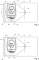
- Figs. 8 and 9 show an embodiment where incoupler structure 14 and/or lateral outcoupler 36 is/are arranged at windows 52, 54 of the document, with the document being, in this case, a banknote.
- These windows 52, 54 are designed to be transparent for at least one wavelength that is coupled in/out by incoupler structure 14 and outcoupler structure 16, respectively.
- transparent advantageously designates that at least 25%, in particular at least 50%, in particular at least 75%, of the light at said wavelength are transmitted through carrier 10 at the location of the window, advantageously without being scattered.
- top designates the side of the document at which lightguide 12 is located
- bottom designates the opposite side.
- first window 52 being located at incoupler structure 14 and second window 54 being located at lateral outcoupler 36.
- incoupler structure 14 there may also be only one such window, e.g. at the location of incoupler structure 14, which would allow to place the document on a light source and illuminate it from below, with light going through first window 52 and being incoupled at incoupler structure 14 and then being seen, from above, at outcoupler structure 16 and/or at any lateral outcoupler 36.
- Fig. 8 and 9 may also be implemented without a lateral outcoupler 36 and/or without second window 54.
- protective area 18 may e.g. cover at least part of another security feature of the banknote, such as its serial number 56.
- incoupler structure 14 and outcoupler structure 16 have been used as incoupler structure 14 and outcoupler structure 16. It must be noted, though, that the same structure can be used for coupling light into lightguide 12 as well as for coupling light out from lightguide 12.
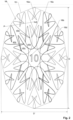
- FIG. 10 An example of such an embodiment is shown in Fig. 10 .
- a structure 15, which can act as incoupler structure 14 as well as outcoupler structure 16, has been provided to extend over protective area 18 (which, in the shown embodiment, basically is equal to the area covered by lightguide 12 because the structure 15 is distributed all over lightguide 12).
- Structure 15 may comprise a plurality of substructures 15a, 15b, 15c..., each of which can couple light into lightguide 12 or out from lightguide 12.
- the substructures 15a, 15b, 15c may be non-interconnected or they may be interconnected.
- Structure 15 advantageously has the properties of outcoupler structure 16 as described herein. In particular, structure 15 advantageously covers less than 10% of protective area 18.
- the shortest distance to structure 15 is advantageously less than D/3, in particular D/4, in particular less than D/10, with D being the longest diameter of protective area 18.
- the convex hull of structure 15 covers at least 75% of the surface of security document 10 and/or of lightguide 12.
- This design allows to place a small light source, such as the flash LED light of a smartphone or a small pocket lamp, anywhere over the convex hull of structure 15 to obtain light incoupling into the lightguide and illumination of the security features and obviates the need for a precise placement even if the light source is close to lightguide 12.
- a small light source such as the flash LED light of a smartphone or a small pocket lamp
- the following condition is advantageously met: for any point in protective area 18, the shortest distance to a part of structure 15 is advantageously less than 5 mm, in particular less than 4 mm, in particular less than 3 mm.
- protective area 18 is elongate, having an elongate direction X along which its diameter is at least 50%, in particular at least 100%, larger than in direction Y perpendicular thereto.
- incoupler structure 14 and/or outcoupler structure 16, or structure 15 in general is advantageously designed to anisotropically couple light into and out of, respectively, lightguide 12, with a preferential direction along direction X.
- This is illustrated for the substructure 15a in Fig. 11 , which illustrates the refractive, reflective or diffractive grating of the substructure 15a to extend along Y, thereby primarily coupling in/out light along X.
- a structure that anisotropically couples light into and out of, respectively, the lightguide 12 along the elongate direction X is a structure that has a higher coupling efficiency Ex for light guided along direction X than the coupling efficiency Ey for light guided along direction Ey, advantageously with Ex > 2 ⁇ Ey.
- Refractive, reflective or diffractive structures to be used in the coupler structures 14, 15, 16 may e.g. be surface structures 23 in lightguide 12 as shown in Figs. 12 and 13 and may be nanostructures as well as microstructures.
- the surface structures 23 are symmetric along direction X, and they therefore have equal coupling efficiency along both vector directions of X, i.e. along +X and along -X.
- the surface structures 23 are asymmetric along direction X, and they therefore have different coupling efficiency along the vector directions of X, i.e. the coupling efficiency along +X and is not the same as the coupling efficiency along -X.
- the substructures 15a, 15b, 15c of the incouplers and/or outcouplers 14, 15, 16 have higher incoupling efficiency for light guided towards the center of protective area 18 than for light guided away from the center of protective area 18, and/or they have higher outcoupling efficiency for light guided away from the center of protective area 18 than for light guided towards the center of protective area 18. This allows to illuminate the larger portion of the protective area with a larger incoupled portion of light provided by a light source.
- Such substructures may be arranged on one or several sides of the center of the lightguide.
- FIGs. 14 and 15 both of which only show two of the (many) coupler substructures at opposite sides from center C of protective area 18, namely the substructures 15a, 15b.
- Fig. 14 shows the preferential incoupling directions I1, 12, i.e. the substructures 15a, 15b couple more guided light into the directions I1, 12 towards the center C of protective area 18 than into the opposite directions.
- Fig. 15 shows the preferential outcoupling directions Ol, 02, i.e. the substructures 15a, 15b couple out more guided light from the directions 11, 12 coming from the center C of protective area 18 than from the opposite directions.
- the incoupling 11, I2 and outcoupling O1, 02 are the time reversal of each other and therefore optimizing for these higher efficiencies using asymmetric couplers can be done simultaneously.
- This design is based on the understanding that, for incoupling, it makes more sense to guide light towards the center C of protective area 18 where there are more outcoupling substructures than towards the edges of protective area 18. And, on the other hand, it makes more sense to optimize the outcouplers for light coming from the center C of protective area 18 than for light coming from the edges of protective area 18 because there is a higher likelihood that the user has coupled in light that arrives at the substructures coming from the center C.
- a bulky light source such as the smartphone surrounding the flash LED of the smartphone, as such light sources will cover a part of the protective area in proximity to the area illuminated by the light source.
- the sparse outcoupler structure 16 advantageously comprises diffractive gratings that are adapted to couple out part of the light guided within lightguide 12.
- such diffractive gratings can be optimized to couple out light coming from a certain direction and/or having a certain wavelength. This can be used to generate selective outcouplers that, for example, are adapted to couple out light from certain directions only.
- outcoupler structure 16 comprises three overlaid outcouplers 16a, 16b, and 16c.
- incoupler structure 14 comprises four spaced-apart incouplers 14a, 14b, and 14c.
- Each of these incouplers is designed to illuminate outcoupler structure 16 from different directions, and each incoupler 14a, 14b, and 14c generates light for one of outcouplers 16a, 16b, and 16c.
- the light from incoupler 14a is coupled out by outcoupler 16a
- the light from incoupler 14b is coupled out by outcoupler 16b
- the light from incoupler 14c is coupled out by outcoupler 16c.
- the three outcouplers 16a, 16c, 16c can be activated sequentially.
- the three outcouplers have different shapes, which allows to sequentially generate three coupled out images of different shapes.
- the three different images correspond to three different positions of a bird in flight.
- the present technique allows to protect a large area of the security document.
- the incouplers and outcouplers are optimized to couple visible light of at least one wavelength between 400 and 1000 nm into and out of lightguide 12.
- they may, for example, also be optimized for infrared light if the security feature is to be detected by a machine.
- the protective area 16 can be used to protect any type of security document.
- protective area 18 can be used to protect a document representing monetary value, such as a banknote, a cheque, or a voucher. As mentioned above, it may, however, also protect an identification document, such as a passport, an ID card, or a personalized access card (identification badge), and in particular the personalized information thereon.
- a document representing monetary value such as a banknote, a cheque, or a voucher.
- an identification document such as a passport, an ID card, or a personalized access card (identification badge), and in particular the personalized information thereon.
- Protective area 18 may also protect a security foil or security patch which is in turn to be applied to an item to be protected.
- Protective area 18 may cover the whole security document or only parts thereof.
- outcoupler structure 16 comprises, in protective area 18, at least one line-shaped outcoupler. It may, however, also comprises differently shaped outcouplers, such as point-shaped outcouplers.
- the outcoupler may form a guilloche pattern. Alternatively or in addition thereto, however, it may also form another pattern, such as a pattern of straight lines, in particular a regular pattern of straight lines, as illustrated in the embodiment of Fig. 4 , which may be easier to visually verify for integrity.
- the outcoupler structure comprises a plurality of, in particular at least 10, in particular at least 100, non-interconnected outcoupler-free regions, e.g. at locations 40a, 40b, 40c, 40d, which are mutually separated by outcoupler structure 16.
- outcoupler structure 16 "fractures" the protective area into a plurality of outcoupler-free regions and protects them without affecting their transparency.
- outcoupler-structure 16 comprises a plurality of, in particular at least 10, in particular at least 100, non-interconnected outcoupler-substructures 16a, 16b, 16c, 16d in protective area 18. Again, this allows to distribute the outcoupler structure sparsely over protective area 18.
- the plurality of outcoupler-substructures 16a, 16b, 16c, 16d is arranged in a regular pattern.
- Regular (i.e. repetitive) patterns have the advantage that a user easily detects any defects therein.
- the shape of the outcoupler-substructures 16a, 16b, 16c, 16d may vary.
- the substructures are short lines.
- they are long lines.
- the substructures may, however, also have different geometrical shape and e.g. form dots, symbols, characters, etc.
- Incoupler structure 14 and/or outcoupler structure 16 may be adapted to respectively in/out couple light from/to below document, provided the carrier 10 is at least partially transparent in the area where the incoupler structure and/or outcoupler structure is located.
- the observation of the outcoupled light can be designed to be on the illumination side or on the opposite side with respect to the illumination side with respect to the document of identification.
- lightguide 12 may (for any embodiments) be strip-shaped, with a length much larger, in particular at least five times larger, than its width, and advantageously with a constant width along its whole length. It may extend across the whole document, i.e. from one of its edges to the opposite edge.
- Protective area 18 may comprise at least one further visual security element, in addition to the outcoupler structures.
- a security element 50 is shown, by way of example, as a dotted cross in Fig. 5 .
- This further security document is visible in reflection, i.e. by shining light onto the lightguide without coupling it into the lightguide. It renders it difficult to place e.g. a false photograph or another counterfeiting element on top the lightguide it without being detected.
- a further security element may be controlled in transmission.
- Such a further visual security element may e.g. be at least one of an optically variable device, such as a diffractive structure, and non-variable markings, such as printed markings.
- Lightguide 10 may be a foil manufactured apart from carrier 10 and then laminated thereto, or it may also be formed in-situ on carrier 10.
- any incoupler and/or outcoupler mentioned herein may e.g. be a diffractive incoupler/outcoupler, a fluorescent/phosphorescent, an Infrared Upconverting incoupler/outcoupler, an incoupler/outcoupler based on microscopic surface structures (i.e. surface structures without diffractive effects, such as microlenses or micro mirrors or surface structures having a lateral repetition period (i.e. a repetition period within the plane of the lightguide) of e.g. at least 10 ⁇ m), diffusing or scattering structures or materials.
- microscopic surface structures i.e. surface structures without diffractive effects, such as microlenses or micro mirrors or surface structures having a lateral repetition period (i.e. a repetition period within the plane of the lightguide) of e.g. at least 10 ⁇ m
- a lateral repetition period i.e. a repetition period within the plane of the lightguide
- the incoupler structure may also be placed e.g. between two ends of the lightguide, e.g. with two protective areas on different, in particular opposite, sides of it.
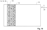
- the lightguide 12 may also e.g. have the shape of a strip or thread extending across the security document as illustrated in Fig. 16 .
Landscapes
- Physics & Mathematics (AREA)
- General Physics & Mathematics (AREA)
- Optics & Photonics (AREA)
- Credit Cards Or The Like (AREA)
- Inspection Of Paper Currency And Valuable Securities (AREA)
- Optical Integrated Circuits (AREA)
- Photo Coupler, Interrupter, Optical-To-Optical Conversion Devices (AREA)
- Measurement Of Force In General (AREA)
Claims (23)
- Un document de sécurité comprenant un guide optique (12), le guide optique (12) comprenant- une structure de coupleur d'entrée (14),- une structure de coupleur de sortie (16),- une zone de protection (18) ayant un diamètre le plus long D,caractérisé en ce que- la structure de coupleur de sortie (16) ne couvre pas plus de 20 % de la zone de protection (18) et- pour chaque point (P) dans la zone de protection (18), une distance la plus courte (d) par rapport à la structure de coupleur de sortie (16) est inférieure à D/3.
- Le document de sécurité selon la revendication 1, dans lequel la structure de coupleur de sortie (16) couvre moins de 10 % de la zone de protection (18).
- Le document de sécurité selon l'une des revendications précédentes, dans lequel, pour chaque point (P) de la zone de protection (18), la distance la plus courte (d) à la structure de coupleur de sortie (16) est inférieure à D/4, notamment inférieure à D/10.
- Le document de sécurité selon l'une des revendications précédentes, dans lequel la zone de protection (18) s'étend sur au moins une zone continue d'au moins 1 cm2, en particulier d'au moins 2 cm2.
- Le document de sécurité selon l'une des revendications précédentes, dans lequel un diamètre le plus court D' et/ou le diamètre le plus long D de la zone de protection (18) est/sont d'au moins 1 cm, en particulier d'au moins 2 cm.
- Le document de sécurité selon l'une des revendications précédentes, dans lequel la distance la plus courte d n'est pas supérieure à 0,5 cm, en particulier pas supérieure à 0,25 cm pour chaque point de la zone de protection (18).
- Le document de sécurité selon l'une des revendications précédentes, dans lequel la structure de coupleur de sortie (16) comprend au moins un découpleur linéaire (20), notamment une pluralité de découpleurs linéaires (20), dans la zone de protection (18), le découpleur linéaire (20) ayant une longueur (L) d'au moins 5 mm, notamment d'au moins 10 mm, et une largeur (w) n'excédant pas 1 mm, notamment n'excédant pas 0,5 mm, notamment n'excédant pas 0,2 mm.
- Le document de sécurité selon la revendication 7, dans lequel la largeur (w) est d'au moins 0,05 mm, en particulier n'est pas supérieure à 0,1 mm.
- Le document de sécurité selon l'une des revendications précédentes, dans lequel le document de sécurité est un document d'identification comprenant des informations personnalisées (28) d'un propriétaire du document d'identification, la zone de protection (18) s'étendant sur au moins une partie des informations personnalisées (28).
- Le document de sécurité selon la revendication 9, dans lequelles informations personnalisées (28) comprennent une photographie (30) et la zone de protection (18) couvre au moins 50 %, en particulier au moins 90 %, de la photographie (30), et/oules informations personnalisées (28) comprennent le nom (32) et/ou la signature (33) du propriétaire et la zone de protection (18) couvre au moins 50 %, en particulier au moins 90 %, du nom (32) et/ou de la signature (33), et/oules informations personnalisées (28) comprennent une puce de mémoire électronique RFID (34) et la zone de protection (18) se superpose à la puce de mémoire (34) et/ou à une antenne reliée à la puce de mémoire (34) .
- Le document de sécurité selon l'une des revendications 9 ou 10, dans lequel la structure de coupleur de sortie (16) représente au moins une partie d'un portrait du propriétaire.
- Le document de sécurité selon l'une des revendications précédentes, dans lequel la zone de protection (18) est convexe, et notamment dans lequel la zone de protection (18) est une enveloppe convexe de la structure de coupleur de sortie (16).
- Le document de sécurité selon l'une des revendications précédentes, comprenant en outre des marquages visibles (24) qui caractérisent un emplacement de la structure de coupleur d'entrée (14), et en particulier dans lequel les marquages (24) ont une extension qui est au moins le double du plus grand diamètre de la structure de coupleur d'entrée.
- Le document de sécurité selon l'une des revendications précédentes, dans lequel la zone de protection (18) comprend une pluralité, en particulier au moins 10, de zones sans coupleur de sortie (40a, 40b, 40c, 40d) non reliées entre elles, qui sont séparées les unes des autres par la structure de coupleur de sortie (16) .
- Le document de sécurité selon l'une des revendications précédentes, dans lequel la structure de coupleur de sortie (16) comprend plusieurs sous-structures de coupleur de sortie (16a, 16b, 16c, 16d) non reliées entre elles, notamment au moins 10, dans la zone de protection (18).
- Le document de sécurité selon l'une des revendications précédentes, comprenant en outre un autre élément de sécurité (50), en plus des structures de coupleur d'entrée et de coupleur de sortie (14, 16), qui est visible en réflexion ou en transmission, et en particulier dans lequel l'autre élément de sécurité (50) est au moins l'un d'un dispositif optiquement variable, tel qu'une structure diffractive, et de marquages non variables, tels que des marquages imprimés.
- Le document de sécurité selon l'une des revendications précédentes, comprenant en outre au moins une fenêtre (52) s'étendant à un endroit où le document de sécurité est placé.
- Le document de sécurité selon l'une des revendications précédentes, dans lequel la structure de coupleur d'entrée (14) et la structure de coupleur de sortie (16) sont une structure commune (15).
- Le document de sécurité selon la revendication 18, dans lequel une enveloppe convexe de la structure commune couvre au moins 75% d'une surface du document de sécurité (10) et/ou du guide optique (12).
- Le document de sécurité selon l'une des revendications 18 ou 19, dans lequel, pour chaque point de la zone de protection (18), une distance la plus courte à une partie de la structure commune (15) est inférieure à 5 mm, en particulier inférieure à 4 mm et en particulier inférieure à 3 mm.
- Le document de sécurité selon l'une des revendications précédentes, dans lequel la zone de protection (18) est allongée et présente une direction longitudinale X, la structure de coupleur d'entrée (14) et/ou la structure de coupleur de sortie (16) couplant la lumière de manière anisotrope dans le guide optique (12) ou la découplant de celui-ci, de préférence le long de la direction longitudinale X.
- Le document de sécurité selon l'une des revendications précédentes, dans lequel la structure de coupleur d'entrée (14) et/ou la structure de coupleur de sortie (16) comprend une pluralité de sous-structures (15a, 15b) qui présentent une efficacité de couplage plus élevée pour la lumière guidée vers un centre (C) de la zone de protection (18) que pour la lumière guidée à partir du centre (C) de la zone de protection (18) et/ou une efficacité de découplage plus élevée pour la lumière guidée à partir du centre (C) de la zone de protection (18) que pour la lumière guidée vers le centre (C) de la zone de protection (18).
- Une feuille de guidage de lumière pour le document selon l'une des revendications précédentes, ladite feuille formant un guide optique (12) comprenant :- une structure de coupleur d'entrée (14),- une structure de coupleur de sortie (16),- une zone de protection (18) présentant un diamètre le plus long D,où- la structure de coupleur de sortie (16) ne couvre pas plus de 20 % de la zone de protection (18) et- pour chaque point (P) dans la zone de protection (18), une distance la plus courte (d) par rapport à la structure de coupleur de sortie (16) est inférieure à D/3.
Applications Claiming Priority (2)
| Application Number | Priority Date | Filing Date | Title |
|---|---|---|---|
| PCT/EP2020/051878 WO2021151459A1 (fr) | 2020-01-27 | 2020-01-27 | Document de sécurité avec guide de lumière présentant une structure de coupleur de sortie peu dense |
| PCT/EP2021/050907 WO2021151699A1 (fr) | 2020-01-27 | 2021-01-18 | Document de sécurité avec guide de lumière présentant une structure de coupleur de sortie peu dense |
Publications (2)
| Publication Number | Publication Date |
|---|---|
| EP4054855A1 EP4054855A1 (fr) | 2022-09-14 |
| EP4054855B1 true EP4054855B1 (fr) | 2023-06-07 |
Family
ID=69400537
Family Applications (1)
| Application Number | Title | Priority Date | Filing Date |
|---|---|---|---|
| EP21700591.7A Active EP4054855B1 (fr) | 2020-01-27 | 2021-01-18 | Document de sécurité avec guide de lumière présentant une structure de coupleur de sortie peu dense |
Country Status (6)
| Country | Link |
|---|---|
| US (1) | US11827046B2 (fr) |
| EP (1) | EP4054855B1 (fr) |
| JP (1) | JP7631352B2 (fr) |
| CN (1) | CN115003515B (fr) |
| IL (1) | IL295158A (fr) |
| WO (2) | WO2021151459A1 (fr) |
Families Citing this family (2)
| Publication number | Priority date | Publication date | Assignee | Title |
|---|---|---|---|---|
| JP7587588B2 (ja) * | 2020-01-27 | 2024-11-20 | オレル フュースリ アクチェンゲゼルシャフト | 光学式ライトガイドを有する身分証明ドキュメント |
| WO2025056167A1 (fr) | 2023-09-14 | 2025-03-20 | Orell Füssli AG | Élément optique de protection à base de guide de lumière pour documents de sécurité et document de sécurité |
Family Cites Families (21)
| Publication number | Priority date | Publication date | Assignee | Title |
|---|---|---|---|---|
| DE3835999C2 (de) | 1988-10-21 | 2001-05-10 | Gao Ges Automation Org | Verfahren und Vorrichtung zum Herstellen eines Identifikationsdokuments in Buchform |
| EP0869408B2 (fr) | 1996-09-19 | 2015-04-29 | Dai Nippon Printing Co., Ltd. | Stratifie avec hologramme en relief et etiquette permettant de preparer un tel stratifie avec hologramme en relief |
| DE10150293B4 (de) * | 2001-10-12 | 2005-05-12 | Ovd Kinegram Ag | Sicherheitselement |
| AU2002367080A1 (en) * | 2002-01-18 | 2003-07-30 | Ovd Kinegram Ag | Diffractive security element having an integrated optical waveguide |
| ES2563755T3 (es) | 2005-05-18 | 2016-03-16 | Visual Physics, Llc | Presentación de imágenes y sistema de seguridad micro-óptico |
| DE102005052326A1 (de) | 2005-11-02 | 2007-05-03 | Giesecke & Devrient Gmbh | Sicherheitselement und Verfahren zu seiner Herstellung |
| JP4882397B2 (ja) | 2006-02-01 | 2012-02-22 | 凸版印刷株式会社 | 表示体、及び表示装置 |
| TW200903465A (en) * | 2007-07-03 | 2009-01-16 | Ind Tech Res Inst | Difrraction grating recording medium |
| CN102138086B (zh) * | 2008-07-10 | 2014-11-26 | 3M创新有限公司 | 具有粘弹性光导的回射制品和装置 |
| DE102008033718B4 (de) * | 2008-07-14 | 2021-07-29 | Bundesdruckerei Gmbh | Sicherheitsdokument mit einem Lichtleiter |
| PL2732978T3 (pl) | 2009-12-18 | 2015-10-30 | Orell Fuessli Sicherheitsdruck Ag | Dokument zabezpieczony z falowodem optycznym |
| AT509928A2 (de) * | 2010-05-26 | 2011-12-15 | Hueck Folien Gmbh | Sicherheitselement mit lichtleiterstrukturen |
| EP2447743B1 (fr) | 2010-11-01 | 2016-10-26 | CSEM Centre Suisse d'Electronique et de Microtechnique SA - Recherche et Développement | Filtre optique isotrope et son procédé de fabrication |
| FR2973917B1 (fr) | 2011-04-08 | 2014-01-10 | Hologram Ind | Composant optique de securite a effet transmissif, fabrication d'un tel composant et document securise equipe d'un tel composant |
| DE102014015282A1 (de) * | 2014-10-16 | 2016-04-21 | Giesecke & Devrient Gmbh | Datenträger mit Lichtleiter |
| EP3205512B1 (fr) * | 2016-02-09 | 2018-06-13 | CSEM Centre Suisse d'Electronique et de Microtechnique SA - Recherche et Développement | Dispositif de sécurité optique |
| JP6776585B2 (ja) | 2016-04-07 | 2020-10-28 | 大日本印刷株式会社 | 偽造防止用樹脂フィルム及び偽造防止物品 |
| EP3470896B1 (fr) * | 2016-06-13 | 2021-02-17 | Dai Nippon Printing Co., Ltd. | Film de guidage de lumière, structure de prévention de falsification et article de prévention de falsification |
| JP7095678B2 (ja) | 2017-03-03 | 2022-07-05 | 大日本印刷株式会社 | 導光体、偽造防止物品 |
| US20200019740A1 (en) | 2017-03-06 | 2020-01-16 | Orell Füssli Sicherheitsdruck Ag | An owner-controlled carrier of value, a payment infrastructure and method for operating this infrastructure |
| US20220009267A1 (en) * | 2018-11-16 | 2022-01-13 | Orell Füssli AG | Waveguide-based anti-forgery security device |
-
2020
- 2020-01-27 WO PCT/EP2020/051878 patent/WO2021151459A1/fr not_active Ceased
-
2021
- 2021-01-18 US US17/795,357 patent/US11827046B2/en active Active
- 2021-01-18 IL IL295158A patent/IL295158A/en unknown
- 2021-01-18 JP JP2022544364A patent/JP7631352B2/ja active Active
- 2021-01-18 EP EP21700591.7A patent/EP4054855B1/fr active Active
- 2021-01-18 CN CN202180010441.8A patent/CN115003515B/zh active Active
- 2021-01-18 WO PCT/EP2021/050907 patent/WO2021151699A1/fr not_active Ceased
Also Published As
| Publication number | Publication date |
|---|---|
| CN115003515A (zh) | 2022-09-02 |
| US20230065749A1 (en) | 2023-03-02 |
| JP7631352B2 (ja) | 2025-02-18 |
| IL295158A (en) | 2022-09-01 |
| EP4054855A1 (fr) | 2022-09-14 |
| WO2021151699A1 (fr) | 2021-08-05 |
| CN115003515B (zh) | 2024-02-27 |
| JP2023535659A (ja) | 2023-08-21 |
| US11827046B2 (en) | 2023-11-28 |
| WO2021151459A1 (fr) | 2021-08-05 |
Similar Documents
| Publication | Publication Date | Title |
|---|---|---|
| KR102488710B1 (ko) | 적층체, 신분증명서, 및, 신분증명서의 검증 방법 | |
| EP2732978A1 (fr) | Document de sécurité avec guide d'ondes optiques | |
| EP2331344B1 (fr) | Document d identification renfermant un motif de sécurité | |
| EP4054855B1 (fr) | Document de sécurité avec guide de lumière présentant une structure de coupleur de sortie peu dense | |
| US9221246B2 (en) | Method for printing an image onto a thermoplastic substrate, pre-forming plate used therefor and security instrument made therefrom | |
| JP4728335B2 (ja) | 偽造防止セキュリティオブジェクト | |
| EP4054852B1 (fr) | Document d'identification avec guide de lumière optique | |
| US12043054B2 (en) | Display | |
| AU2007306918B2 (en) | A security document with micro-prisms | |
| US20160039241A1 (en) | Security document and a method of detecting the edge of a security document | |
| KR101682015B1 (ko) | 시야각 제한 보안 필름 | |
| EP4729303A1 (fr) | Structures micro-optiques stratifiées | |
| KR100781740B1 (ko) | 유가증권의 위조방지방법 | |
| AU2013100406B4 (en) | Diffractive Edge Guide for Banknotes | |
| JP2025531283A (ja) | 独立した光源を有するデータキャリア及びその製造方法 |
Legal Events
| Date | Code | Title | Description |
|---|---|---|---|
| STAA | Information on the status of an ep patent application or granted ep patent |
Free format text: STATUS: UNKNOWN |
|
| STAA | Information on the status of an ep patent application or granted ep patent |
Free format text: STATUS: THE INTERNATIONAL PUBLICATION HAS BEEN MADE |
|
| PUAI | Public reference made under article 153(3) epc to a published international application that has entered the european phase |
Free format text: ORIGINAL CODE: 0009012 |
|
| STAA | Information on the status of an ep patent application or granted ep patent |
Free format text: STATUS: REQUEST FOR EXAMINATION WAS MADE |
|
| 17P | Request for examination filed |
Effective date: 20220608 |
|
| AK | Designated contracting states |
Kind code of ref document: A1 Designated state(s): AL AT BE BG CH CY CZ DE DK EE ES FI FR GB GR HR HU IE IS IT LI LT LU LV MC MK MT NL NO PL PT RO RS SE SI SK SM TR |
|
| GRAP | Despatch of communication of intention to grant a patent |
Free format text: ORIGINAL CODE: EPIDOSNIGR1 |
|
| STAA | Information on the status of an ep patent application or granted ep patent |
Free format text: STATUS: GRANT OF PATENT IS INTENDED |
|
| DAV | Request for validation of the european patent (deleted) | ||
| DAX | Request for extension of the european patent (deleted) | ||
| INTG | Intention to grant announced |
Effective date: 20230112 |
|
| GRAS | Grant fee paid |
Free format text: ORIGINAL CODE: EPIDOSNIGR3 |
|
| GRAA | (expected) grant |
Free format text: ORIGINAL CODE: 0009210 |
|
| STAA | Information on the status of an ep patent application or granted ep patent |
Free format text: STATUS: THE PATENT HAS BEEN GRANTED |
|
| AK | Designated contracting states |
Kind code of ref document: B1 Designated state(s): AL AT BE BG CH CY CZ DE DK EE ES FI FR GB GR HR HU IE IS IT LI LT LU LV MC MK MT NL NO PL PT RO RS SE SI SK SM TR |
|
| REG | Reference to a national code |
Ref country code: GB Ref legal event code: FG4D |
|
| P01 | Opt-out of the competence of the unified patent court (upc) registered |
Effective date: 20230405 |
|
| REG | Reference to a national code |
Ref country code: CH Ref legal event code: EP Ref country code: AT Ref legal event code: REF Ref document number: 1573908 Country of ref document: AT Kind code of ref document: T Effective date: 20230615 Ref country code: DE Ref legal event code: R096 Ref document number: 602021002814 Country of ref document: DE |
|
| REG | Reference to a national code |
Ref country code: LT Ref legal event code: MG9D |
|
| REG | Reference to a national code |
Ref country code: SE Ref legal event code: TRGR |
|
| REG | Reference to a national code |
Ref country code: NL Ref legal event code: MP Effective date: 20230607 |
|
| PG25 | Lapsed in a contracting state [announced via postgrant information from national office to epo] |
Ref country code: NO Free format text: LAPSE BECAUSE OF FAILURE TO SUBMIT A TRANSLATION OF THE DESCRIPTION OR TO PAY THE FEE WITHIN THE PRESCRIBED TIME-LIMIT Effective date: 20230907 Ref country code: ES Free format text: LAPSE BECAUSE OF FAILURE TO SUBMIT A TRANSLATION OF THE DESCRIPTION OR TO PAY THE FEE WITHIN THE PRESCRIBED TIME-LIMIT Effective date: 20230607 |
|
| REG | Reference to a national code |
Ref country code: AT Ref legal event code: MK05 Ref document number: 1573908 Country of ref document: AT Kind code of ref document: T Effective date: 20230607 |
|
| PG25 | Lapsed in a contracting state [announced via postgrant information from national office to epo] |
Ref country code: RS Free format text: LAPSE BECAUSE OF FAILURE TO SUBMIT A TRANSLATION OF THE DESCRIPTION OR TO PAY THE FEE WITHIN THE PRESCRIBED TIME-LIMIT Effective date: 20230607 Ref country code: NL Free format text: LAPSE BECAUSE OF FAILURE TO SUBMIT A TRANSLATION OF THE DESCRIPTION OR TO PAY THE FEE WITHIN THE PRESCRIBED TIME-LIMIT Effective date: 20230607 Ref country code: LV Free format text: LAPSE BECAUSE OF FAILURE TO SUBMIT A TRANSLATION OF THE DESCRIPTION OR TO PAY THE FEE WITHIN THE PRESCRIBED TIME-LIMIT Effective date: 20230607 Ref country code: LT Free format text: LAPSE BECAUSE OF FAILURE TO SUBMIT A TRANSLATION OF THE DESCRIPTION OR TO PAY THE FEE WITHIN THE PRESCRIBED TIME-LIMIT Effective date: 20230607 Ref country code: HR Free format text: LAPSE BECAUSE OF FAILURE TO SUBMIT A TRANSLATION OF THE DESCRIPTION OR TO PAY THE FEE WITHIN THE PRESCRIBED TIME-LIMIT Effective date: 20230607 Ref country code: GR Free format text: LAPSE BECAUSE OF FAILURE TO SUBMIT A TRANSLATION OF THE DESCRIPTION OR TO PAY THE FEE WITHIN THE PRESCRIBED TIME-LIMIT Effective date: 20230908 |
|
| PG25 | Lapsed in a contracting state [announced via postgrant information from national office to epo] |
Ref country code: FI Free format text: LAPSE BECAUSE OF FAILURE TO SUBMIT A TRANSLATION OF THE DESCRIPTION OR TO PAY THE FEE WITHIN THE PRESCRIBED TIME-LIMIT Effective date: 20230607 |
|
| PG25 | Lapsed in a contracting state [announced via postgrant information from national office to epo] |
Ref country code: SK Free format text: LAPSE BECAUSE OF FAILURE TO SUBMIT A TRANSLATION OF THE DESCRIPTION OR TO PAY THE FEE WITHIN THE PRESCRIBED TIME-LIMIT Effective date: 20230607 |
|
| PG25 | Lapsed in a contracting state [announced via postgrant information from national office to epo] |
Ref country code: IS Free format text: LAPSE BECAUSE OF FAILURE TO SUBMIT A TRANSLATION OF THE DESCRIPTION OR TO PAY THE FEE WITHIN THE PRESCRIBED TIME-LIMIT Effective date: 20231007 |
|
| PG25 | Lapsed in a contracting state [announced via postgrant information from national office to epo] |
Ref country code: SM Free format text: LAPSE BECAUSE OF FAILURE TO SUBMIT A TRANSLATION OF THE DESCRIPTION OR TO PAY THE FEE WITHIN THE PRESCRIBED TIME-LIMIT Effective date: 20230607 Ref country code: SK Free format text: LAPSE BECAUSE OF FAILURE TO SUBMIT A TRANSLATION OF THE DESCRIPTION OR TO PAY THE FEE WITHIN THE PRESCRIBED TIME-LIMIT Effective date: 20230607 Ref country code: RO Free format text: LAPSE BECAUSE OF FAILURE TO SUBMIT A TRANSLATION OF THE DESCRIPTION OR TO PAY THE FEE WITHIN THE PRESCRIBED TIME-LIMIT Effective date: 20230607 Ref country code: PT Free format text: LAPSE BECAUSE OF FAILURE TO SUBMIT A TRANSLATION OF THE DESCRIPTION OR TO PAY THE FEE WITHIN THE PRESCRIBED TIME-LIMIT Effective date: 20231009 Ref country code: IS Free format text: LAPSE BECAUSE OF FAILURE TO SUBMIT A TRANSLATION OF THE DESCRIPTION OR TO PAY THE FEE WITHIN THE PRESCRIBED TIME-LIMIT Effective date: 20231007 Ref country code: EE Free format text: LAPSE BECAUSE OF FAILURE TO SUBMIT A TRANSLATION OF THE DESCRIPTION OR TO PAY THE FEE WITHIN THE PRESCRIBED TIME-LIMIT Effective date: 20230607 Ref country code: CZ Free format text: LAPSE BECAUSE OF FAILURE TO SUBMIT A TRANSLATION OF THE DESCRIPTION OR TO PAY THE FEE WITHIN THE PRESCRIBED TIME-LIMIT Effective date: 20230607 Ref country code: AT Free format text: LAPSE BECAUSE OF FAILURE TO SUBMIT A TRANSLATION OF THE DESCRIPTION OR TO PAY THE FEE WITHIN THE PRESCRIBED TIME-LIMIT Effective date: 20230607 |
|
| PG25 | Lapsed in a contracting state [announced via postgrant information from national office to epo] |
Ref country code: PL Free format text: LAPSE BECAUSE OF FAILURE TO SUBMIT A TRANSLATION OF THE DESCRIPTION OR TO PAY THE FEE WITHIN THE PRESCRIBED TIME-LIMIT Effective date: 20230607 |
|
| REG | Reference to a national code |
Ref country code: DE Ref legal event code: R097 Ref document number: 602021002814 Country of ref document: DE |
|
| PLBE | No opposition filed within time limit |
Free format text: ORIGINAL CODE: 0009261 |
|
| STAA | Information on the status of an ep patent application or granted ep patent |
Free format text: STATUS: NO OPPOSITION FILED WITHIN TIME LIMIT |
|
| PG25 | Lapsed in a contracting state [announced via postgrant information from national office to epo] |
Ref country code: DK Free format text: LAPSE BECAUSE OF FAILURE TO SUBMIT A TRANSLATION OF THE DESCRIPTION OR TO PAY THE FEE WITHIN THE PRESCRIBED TIME-LIMIT Effective date: 20230607 |
|
| PG25 | Lapsed in a contracting state [announced via postgrant information from national office to epo] |
Ref country code: SI Free format text: LAPSE BECAUSE OF FAILURE TO SUBMIT A TRANSLATION OF THE DESCRIPTION OR TO PAY THE FEE WITHIN THE PRESCRIBED TIME-LIMIT Effective date: 20230607 |
|
| 26N | No opposition filed |
Effective date: 20240308 |
|
| PG25 | Lapsed in a contracting state [announced via postgrant information from national office to epo] |
Ref country code: SI Free format text: LAPSE BECAUSE OF FAILURE TO SUBMIT A TRANSLATION OF THE DESCRIPTION OR TO PAY THE FEE WITHIN THE PRESCRIBED TIME-LIMIT Effective date: 20230607 Ref country code: IT Free format text: LAPSE BECAUSE OF FAILURE TO SUBMIT A TRANSLATION OF THE DESCRIPTION OR TO PAY THE FEE WITHIN THE PRESCRIBED TIME-LIMIT Effective date: 20230607 |
|
| PG25 | Lapsed in a contracting state [announced via postgrant information from national office to epo] |
Ref country code: MC Free format text: LAPSE BECAUSE OF FAILURE TO SUBMIT A TRANSLATION OF THE DESCRIPTION OR TO PAY THE FEE WITHIN THE PRESCRIBED TIME-LIMIT Effective date: 20230607 |
|
| PG25 | Lapsed in a contracting state [announced via postgrant information from national office to epo] |
Ref country code: MC Free format text: LAPSE BECAUSE OF FAILURE TO SUBMIT A TRANSLATION OF THE DESCRIPTION OR TO PAY THE FEE WITHIN THE PRESCRIBED TIME-LIMIT Effective date: 20230607 |
|
| PG25 | Lapsed in a contracting state [announced via postgrant information from national office to epo] |
Ref country code: LU Free format text: LAPSE BECAUSE OF NON-PAYMENT OF DUE FEES Effective date: 20240118 |
|
| PG25 | Lapsed in a contracting state [announced via postgrant information from national office to epo] |
Ref country code: LU Free format text: LAPSE BECAUSE OF NON-PAYMENT OF DUE FEES Effective date: 20240118 |
|
| PG25 | Lapsed in a contracting state [announced via postgrant information from national office to epo] |
Ref country code: BE Free format text: LAPSE BECAUSE OF NON-PAYMENT OF DUE FEES Effective date: 20240131 |
|
| PG25 | Lapsed in a contracting state [announced via postgrant information from national office to epo] |
Ref country code: BE Free format text: LAPSE BECAUSE OF NON-PAYMENT OF DUE FEES Effective date: 20240131 |
|
| REG | Reference to a national code |
Ref country code: BE Ref legal event code: MM Effective date: 20240131 |
|
| PG25 | Lapsed in a contracting state [announced via postgrant information from national office to epo] |
Ref country code: BG Free format text: LAPSE BECAUSE OF FAILURE TO SUBMIT A TRANSLATION OF THE DESCRIPTION OR TO PAY THE FEE WITHIN THE PRESCRIBED TIME-LIMIT Effective date: 20230607 |
|
| PG25 | Lapsed in a contracting state [announced via postgrant information from national office to epo] |
Ref country code: BG Free format text: LAPSE BECAUSE OF FAILURE TO SUBMIT A TRANSLATION OF THE DESCRIPTION OR TO PAY THE FEE WITHIN THE PRESCRIBED TIME-LIMIT Effective date: 20230607 |
|
| PG25 | Lapsed in a contracting state [announced via postgrant information from national office to epo] |
Ref country code: IE Free format text: LAPSE BECAUSE OF NON-PAYMENT OF DUE FEES Effective date: 20240118 |
|
| PG25 | Lapsed in a contracting state [announced via postgrant information from national office to epo] |
Ref country code: IE Free format text: LAPSE BECAUSE OF NON-PAYMENT OF DUE FEES Effective date: 20240118 |
|
| PGFP | Annual fee paid to national office [announced via postgrant information from national office to epo] |
Ref country code: MT Payment date: 20241226 Year of fee payment: 5 |
|
| PGFP | Annual fee paid to national office [announced via postgrant information from national office to epo] |
Ref country code: SE Payment date: 20250121 Year of fee payment: 5 |
|
| PGFP | Annual fee paid to national office [announced via postgrant information from national office to epo] |
Ref country code: CH Payment date: 20250201 Year of fee payment: 5 |
|
| PG25 | Lapsed in a contracting state [announced via postgrant information from national office to epo] |
Ref country code: CY Free format text: LAPSE BECAUSE OF FAILURE TO SUBMIT A TRANSLATION OF THE DESCRIPTION OR TO PAY THE FEE WITHIN THE PRESCRIBED TIME-LIMIT; INVALID AB INITIO Effective date: 20210118 |
|
| PG25 | Lapsed in a contracting state [announced via postgrant information from national office to epo] |
Ref country code: HU Free format text: LAPSE BECAUSE OF FAILURE TO SUBMIT A TRANSLATION OF THE DESCRIPTION OR TO PAY THE FEE WITHIN THE PRESCRIBED TIME-LIMIT; INVALID AB INITIO Effective date: 20210118 |
|
| PG25 | Lapsed in a contracting state [announced via postgrant information from national office to epo] |
Ref country code: TR Free format text: LAPSE BECAUSE OF FAILURE TO SUBMIT A TRANSLATION OF THE DESCRIPTION OR TO PAY THE FEE WITHIN THE PRESCRIBED TIME-LIMIT Effective date: 20230607 |
|
| REG | Reference to a national code |
Ref country code: CH Ref legal event code: U11 Free format text: ST27 STATUS EVENT CODE: U-0-0-U10-U11 (AS PROVIDED BY THE NATIONAL OFFICE) Effective date: 20260201 |
|
| PGFP | Annual fee paid to national office [announced via postgrant information from national office to epo] |
Ref country code: GB Payment date: 20260123 Year of fee payment: 6 |
|
| PGFP | Annual fee paid to national office [announced via postgrant information from national office to epo] |
Ref country code: DE Payment date: 20260121 Year of fee payment: 6 |
|
| PGFP | Annual fee paid to national office [announced via postgrant information from national office to epo] |
Ref country code: FR Payment date: 20260123 Year of fee payment: 6 |