EP4055339B1 - Système et procédé électrohydrodynamique - Google Patents
Système et procédé électrohydrodynamique Download PDFInfo
- Publication number
- EP4055339B1 EP4055339B1 EP20803785.3A EP20803785A EP4055339B1 EP 4055339 B1 EP4055339 B1 EP 4055339B1 EP 20803785 A EP20803785 A EP 20803785A EP 4055339 B1 EP4055339 B1 EP 4055339B1
- Authority
- EP
- European Patent Office
- Prior art keywords
- fluid
- ehd
- dielectric fluid
- enclosure
- thermal management
- Prior art date
- Legal status (The legal status is an assumption and is not a legal conclusion. Google has not performed a legal analysis and makes no representation as to the accuracy of the status listed.)
- Active
Links
Images

Classifications
-
- H—ELECTRICITY
- H05—ELECTRIC TECHNIQUES NOT OTHERWISE PROVIDED FOR
- H05K—PRINTED CIRCUITS; CASINGS OR CONSTRUCTIONAL DETAILS OF ELECTRIC APPARATUS; MANUFACTURE OF ASSEMBLAGES OF ELECTRICAL COMPONENTS
- H05K7/00—Constructional details common to different types of electric apparatus
- H05K7/20—Modifications to facilitate cooling, ventilating, or heating
- H05K7/20218—Modifications to facilitate cooling, ventilating, or heating using a liquid coolant without phase change in electronic enclosures
- H05K7/20281—Thermal management, e.g. liquid flow control
-
- F—MECHANICAL ENGINEERING; LIGHTING; HEATING; WEAPONS; BLASTING
- F28—HEAT EXCHANGE IN GENERAL
- F28F—DETAILS OF HEAT-EXCHANGE AND HEAT-TRANSFER APPARATUS, OF GENERAL APPLICATION
- F28F13/00—Arrangements for modifying heat-transfer, e.g. increasing, decreasing
- F28F13/16—Arrangements for modifying heat-transfer, e.g. increasing, decreasing by applying an electrostatic field to the body of the heat-exchange medium
-
- F—MECHANICAL ENGINEERING; LIGHTING; HEATING; WEAPONS; BLASTING
- F04—POSITIVE - DISPLACEMENT MACHINES FOR LIQUIDS; PUMPS FOR LIQUIDS OR ELASTIC FLUIDS
- F04B—POSITIVE-DISPLACEMENT MACHINES FOR LIQUIDS; PUMPS
- F04B17/00—Pumps characterised by combination with, or adaptation to, specific driving engines or motors
-
- F—MECHANICAL ENGINEERING; LIGHTING; HEATING; WEAPONS; BLASTING
- F04—POSITIVE - DISPLACEMENT MACHINES FOR LIQUIDS; PUMPS FOR LIQUIDS OR ELASTIC FLUIDS
- F04B—POSITIVE-DISPLACEMENT MACHINES FOR LIQUIDS; PUMPS
- F04B19/00—Machines or pumps having pertinent characteristics not provided for in, or of interest apart from, groups F04B1/00 - F04B17/00
- F04B19/006—Micropumps
-
- F—MECHANICAL ENGINEERING; LIGHTING; HEATING; WEAPONS; BLASTING
- F04—POSITIVE - DISPLACEMENT MACHINES FOR LIQUIDS; PUMPS FOR LIQUIDS OR ELASTIC FLUIDS
- F04B—POSITIVE-DISPLACEMENT MACHINES FOR LIQUIDS; PUMPS
- F04B19/00—Machines or pumps having pertinent characteristics not provided for in, or of interest apart from, groups F04B1/00 - F04B17/00
- F04B19/04—Pumps for special use
-
- G—PHYSICS
- G21—NUCLEAR PHYSICS; NUCLEAR ENGINEERING
- G21K—HANDLING OF PARTICLES OR IONISING RADIATION NOT OTHERWISE PROVIDED FOR; IRRADIATION DEVICES; GAMMA RAY OR X-RAY MICROSCOPES
- G21K5/00—Irradiation devices
-
- H—ELECTRICITY
- H05—ELECTRIC TECHNIQUES NOT OTHERWISE PROVIDED FOR
- H05K—PRINTED CIRCUITS; CASINGS OR CONSTRUCTIONAL DETAILS OF ELECTRIC APPARATUS; MANUFACTURE OF ASSEMBLAGES OF ELECTRICAL COMPONENTS
- H05K7/00—Constructional details common to different types of electric apparatus
- H05K7/20—Modifications to facilitate cooling, ventilating, or heating
- H05K7/20218—Modifications to facilitate cooling, ventilating, or heating using a liquid coolant without phase change in electronic enclosures
- H05K7/20236—Modifications to facilitate cooling, ventilating, or heating using a liquid coolant without phase change in electronic enclosures by immersion
Definitions
- the present invention relates to electrohydrodynamics (EHD), and more specifically to the use of EHD for thermal management of heat generating components.
- electrohydrodynamic thermal management systems in which an electrical field is used to create a flow in a dielectric fluid. This may prove more efficient than, for example, a traditional fan cooling.
- electrohydrodynamic thermal management systems offers thermal management by circulating a thermal management fluid in a relatively energy efficient manner, there is a need for an increased efficiency in EHD thermal management systems.
- An electrohydrodynamic thermal management system is for example disclosed in document US 4 396 055 A .
- An object of the present invention is to provide a method of altering one or more properties of a dielectric fluid for use in an EHD thermal management system.
- the method is defined by the subject-matter of claim 1.
- the system may comprise at least one EHD pump unit comprising at least two electrodes for pumping the dielectric fluid, and an enclosure for accommodating the fluid within the system.
- the method may comprise the steps of exposing the dielectric fluid to an ionizing process configured to ionize the dielectric fluid, and to operate the pump unit to circulate or at least cause the exposed fluid to flow in the EHD system.
- the ionizing process may comprise an ionizing irradiation of the dielectric fluid.
- the dielectric fluid is exposed to the ionizing process in at least one of: a part of the enclosure, wherein a wall portion of the enclosure is exposed to the ionizing process, a location separated from the EHD thermal management system, from which the fluid is added to the EHD thermal management system after exposure, and within the enclosure, wherein the dielectric fluid is exposed to the ionizing process by a substance located within said enclosure.
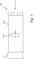
- the present invention is based on the realization that by exposing the dielectric fluid to an ionizing process configured to ionize the dielectric fluid, the pumping efficiency may be improved. This allows for an increased flow rate compared to non-ionized liquid, and thus a better cooling effect.
- the proposed EHD system may comprise at least one pump unit that may be arranged within, or connected to, the enclosure in which the dielectric fluid is held.
- a cooling effect may be achieved by allowing the dielectric fluid to flow in order to transport heat energy away from the component, or area, in need of cooling.
- a heating effect may be achieved by allowing the dielectric fluid to flow in order to transport heat energy to the component or region to be heated.
- the EHD system may be arranged to allow the dielectric fluid to circulate between a heat generating side of the system and a cooling side of the system, which for example may comprise a heat exchanger or heat sink.
- the pump unit may be configured to create a flow in the fluid.
- the pump unit may comprise at least two electrodes, which may be separated from each other such that a second one of the electrodes is located in a downstream direction from a first one of the electrodes.
- the two electrodes may be connectable to a voltage source to create a field that affects the dielectric fluid such that a flow is created.
- the flow rate may be changed by varying the voltage applied to the electrodes. By decreasing the voltage, the fluid may lose momentum and the flow be decreased. Thus, by controlling the voltage, the cooling effect of the system can be adjusted.
- At least one of the electrode(s), such as the emitter electrode, may be elongated in the flow direction, such that a height as seen in the flow direction is greater than a width as seen in a directions orthogonal to the flow direction.
- This configuration may improve the electric field properties with respect to the corona discharge, which is believed to be the underlying mechanism accelerating the fluid between the electrodes.
- the ionizing process it is here meant a process which is configured to ionize the dielectric fluid. More specifically, the ionizing process may encompass exposing the dielectric fluid to a radiation process that carries sufficient energy or is otherwise able to detach electrons from atoms or molecules.
- the ionizing process may comprise an ionizing irradiation of the dielectric fluid.
- the ionizing process may alternatively, or in combination with the (ir)radiation, comprise subjecting the dielectric fluid to one or more ionizing additives.
- dielectric fluid without acquiescing to a particular physical model, exposing the dielectric fluid to an ionizing process is believed to cause the fluid to ionize and break down into other more easily ionizable chains of molecules.
- This altering of the characteristics of dielectric fluid may, when used in an EHD system, improve the pumping effect induced by the electrical field of the EHD unit and cause the fluid to flow at a higher velocity compared to what would have been achieved if the dielectric fluid were not exposed to such ionization process.
- the increased flow will in a thermal management system mean a greater cooling effect and improved power efficiency.
- the dielectric fluid may be ionized at different stages of the EHD system's lifetime. Further, the ionization may also be carried out at different locations within or outside the EHD system. For example, the entire system, or only a part of it, such as the enclosure, could be exposed to a radiation from the outside, whilst the dielectric fluid is located within the system. In another example the dielectric fluid may be exposed to a radiation, or an ionizing additive, at a location separated from the enclosure and then added to the system at a later stage. Yet another example may be to add a small substance of radiating material, or an additive to the system, preferably within the enclosure, in order to expose the dielectric fluid to the ionization as it flows in the system. This may allow for the dielectric fluid to be exposed continuously, throughout the use of the system.
- an EHD thermal management system comprising at least one pump unit, configured in a manner as previously described.
- the system is defined by the subject-matter of claim 8.
- the system may comprise a dielectric fluid.
- the EHD thermal management system comprises at least two electrodes for pumping the dielectric fluid, and at least one enclosure for accommodating said dielectric fluid.
- the EHD thermal management system is configured to expose the dielectric fluid to an ionizing process configured to ionize the dielectric fluid.
- the EHD system utilizes the characteristics of dielectric fluid exposed to the ionizing process. This may improve the pumping effect induced by the electrical field of the EHD unit and cause the fluid to flow at a higher velocity compared to what would have been achieved if the dielectric fluid was not exposed to such ionization process.
- the EHD thermal management system proposed may thus feature a greater cooling effect and an improved power efficiency.
- the ionizing process of the EHD system may comprise any steps of the ionizing process as previously described.
- first and second aspect of the present invention share a common general inventive concept or idea wherein dielectric fluid is exposed to an ionizing process.
- dielectric fluid a dielectric material in a liquid or fluid state.
- dielectric fluids that can be pumped by means of embodiments of the invention may encompass 3M TM Novec TM (7000, 7100, 7200, 7500, 7700, 72DE, 71 DA), Galden ® HT (70, 110, 135, 72DE, 71DA), fluorinated fluids, hydrocarbon fluids, etc., or a combination thereof.
- the dielectric fluid may further comprise at least one additive.
- the additive may be in a fluid form or a solid form.
- the additive may comprise a salt or any other form of ions which may be added to, and preferably dissolved in, the dielectric fluid. This may advantageously further increase the ionizing process of the dielectric fluid.
- the ionizing process comprises an ionizing irradiation of the dielectric fluid.
- the dielectric fluid may be ionized in an efficient manner and/or during a relatively long period of time. This may, for example, be advantageous in areas where a continuous exposure to an ionizing process is desired.
- the ionizing irradiation is generated from at least one radioactive isotope.
- the radioactive isotope may for example comprise, but is not limited to, Cobolt 60 or Americum.
- the ionizing (ir)radiation may further be generated from an electrically generated X-ray radiation. This is advantageous as the source of the ionizing radiation may be selected, for example, depending on the intended use, availability and/or cost efficiency.
- different radioactive isotopes may offer different levels of ionizing radiation and may thus be suitable in different systems. This may allow for a more accessible and cost-efficient system which furthermore may be customized for specific preconditions.
- the dielectric fluid is selected from the group consisting of a fluorinated fluid and a hydrocarbon fluid.
- the dielectric fluid may alternatively comprise a combination of the dielectric fluid as exemplified and other molecules or additives. It will be appreciated that combinations thereof may further increase the efficiency of the dielectric fluid in an EHD thermal management system.
- the enclosure may take the form of an enclosed passage, for example, defining a closed loop, adapted to convey a circulating flow of fluid.
- This specific configuration of the enclosure may be advantageous as the specific enclosure may provide a more efficient flow, as all fluid within the enclosure will be encouraged to move in the same direction.
- the pump unit is arranged in order to cover an entire cross-section of the closed loop configured enclosure. This is advantageous as a maximal amount of dielectric fluid in the given cross section will be subject to the pump unit, in other words, all fluid has to pass through the pump unit in order to circulate. As a result, an increased efficiency of the circulation of the dielectric fluid, and thus also the cooling effect, may be achieved. Further, the pump unit may not only be capable of inducing a flow in the dielectric fluid, but also to impede or even prevent the flow. In other words, the pump unit may be configured to operate as a switch capable of opening and closing the passage, which allows for an improved control of the flow.
- the at least two electrodes of the pump unit are arranged in a grid structure.
- electrodes may be positioned either in a common plane or in different layers. Utilizing a grid structure may allow a further increase in the efficiency of the pump unit and allows for an increased control of the thermal management system.
- the dielectric fluid may be exposed to radiation at different points in time, locations, to a certain amount, or using different radiating source materials and dielectric fluids, and that the examples discussed with reference to the appended drawings merely are illustrative examples.
- the fluid may be exposed to radiation separately from the EHD system and added to the system at a later stage. It will be appreciated that not the entire amount of said fluid has to be exposed to radiation. In some examples, exposed fluid could be added to the fluid in the EHD system, thus forming a radiated additive to the total amount of fluid in the system.
- the radiation may be provided from within the enclosure as well as from a source positioned outside the enclosure and/or the entire system. One example of such arrangement is disclosed in Figure 3 .
- Figure 3 depicts an embodiment in which the enclosure 120 is formed as a passage leading fluid through a closed loop.
- the enclosure 120 may e.g. be formed as a tube or channel wherein the end is connected to the beginning in order to allow for a continuous and repeated flow of a circulating fluid in a closed loop system.
- the pump unit 110 may be arranged to cover an entire cross section of the enclosure 120, as indicated in Figure 3 .
- the pump unit 110 may cover only a part of the cross section in order to allow fluid to pass at the side of the pump unit 100.
- the pump unit 110 may not only be capable of inducing a flow F in the dielectric fluid, but also to impede or even prevent the flow F.
- the pump unit 110 may be configured to operate as a switch capable of opening and closing the passage 120, which allows for an improved control of the flow.
- the irradiation 122 of the fluid may in this example be provided from outside of the system. As depicted, part of the enclosure may be subject to ionizing radiation 122, which may penetrate the wall of the enclosure and reach the dielectric fluid. Other embodiments may have the enclosure 120 exposed to radiation 122 in its entity.
- the radiating source 130 may be placed directly on the system or distanced from it.
Landscapes
- Engineering & Computer Science (AREA)
- General Engineering & Computer Science (AREA)
- Mechanical Engineering (AREA)
- Physics & Mathematics (AREA)
- Thermal Sciences (AREA)
- Microelectronics & Electronic Packaging (AREA)
- High Energy & Nuclear Physics (AREA)
- Cooling Or The Like Of Electrical Apparatus (AREA)
- X-Ray Techniques (AREA)
- Structures Of Non-Positive Displacement Pumps (AREA)
- Liquid Crystal Substances (AREA)
- Investigating Or Analyzing Materials By The Use Of Electric Means (AREA)
Claims (15)
- Procédé destiné à modifier une ou plusieurs propriétés d'un fluide diélectrique à utiliser dans un système (100) de gestion thermique électrohydrodynamique, EHD, le système comprenant une source de rayonnement, au moins une unité de pompage EHD (110) comprenant au moins deux électrodes pour pomper le fluide diélectrique et au moins une enceinte (120) pour accueillir le fluide à l'intérieur du système, le procédé comprenant :l'exposition du fluide diélectrique à une irradiation ionisante (122) depuis la source de rayonnement, l'irradiation ionisante étant configurée pour ioniser le fluide diélectrique ; etle fonctionnement de l'unité de pompage pour faire circuler le fluide exposé dans l'enceinte ;dans lequel le fluide diélectrique est exposé à l'irradiation ionisante depuis la source de rayonnement à au moins un endroit parmi :une partie de ladite enceinte, une partie de paroi de l'enceinte étant exposée à ladite irradiation ionisante,un emplacement séparé dudit système de gestion thermique EHD, depuis lequel le fluide est ajouté audit système de gestion thermique EHD après exposition, età l'intérieur de ladite enceinte, le fluide diélectrique étant exposé à l'irradiation ionisante par une substance (130) située à l'intérieur de ladite enceinte.
- Procédé selon la revendication 1, dans lequel l'irradiation ionisante est générée à partir d'un isotope radioactif et/ou d'un rayonnement de rayons X généré électriquement.
- Procédé selon une quelconque revendication précédente, dans lequel le fluide diélectrique est choisi dans le groupe constitué par un fluide fluoré et un fluide hydrocarboné.
- Procédé selon une quelconque revendication précédente, dans lequel le fluide diélectrique comprend en outre au moins un additif.
- Procédé selon une quelconque revendication précédente, dans lequel l'enceinte est formée comme un passage fermé adapté pour transporter un flux circulant du fluide.
- Procédé selon la revendication 5, dans lequel l'unité de pompage est agencée pour couvrir une section transversale entière du passage.
- Procédé selon une quelconque revendication précédente, dans lequel les au moins deux électrodes sont formées comme des structures de grille.
- Système (100) de gestion thermique électrohydrodynamique, EHD, comprenant une source de rayonnement, au moins une unité de pompage (110) comprenant au moins deux électrodes pour pomper un fluide diélectrique, et au moins une enceinte (120) pour accueillir ledit fluide diélectrique, le système de gestion thermique EHD étant configuré pour exposer le fluide diélectrique à une irradiation isolante (122) depuis la source de rayonnement configurée pour ioniser le fluide diélectrique.
- Système de gestion thermique EHD selon la revendication 8, dans lequel le fluide diélectrique est exposé à l'irradiation ionisante depuis la source de rayonnement à au moins un endroit parmi :une partie de ladite enceinte, une partie de paroi de l'enceinte étant exposée à ladite irradiation ionisante,un emplacement séparé dudit système de gestion thermique EHD, depuis lequel le fluide est ajouté audit système de gestion thermique EHD après exposition, età l'intérieur de ladite enceinte, le fluide diélectrique étant exposé à l'irradiation ionisante par une substance (130) située à l'intérieur de ladite enceinte.
- Système de gestion thermique EHD selon la revendication 9, dans lequel l'irradiation ionisante est générée à partir d'un isotope radioactif et/ou d'un rayonnement de rayons X généré électriquement.
- Système de gestion thermique EHD selon l'une quelconque des revendications 8 à 10, dans lequel le fluide diélectrique est choisi dans le groupe constitué par un fluide fluoré et un fluide hydrocarboné.
- Système de gestion thermique EHD selon l'une quelconque des revendications 8 à 11, dans lequel le fluide diélectrique comprend en outre au moins un additif.
- Système de gestion thermique EHD selon l'une quelconque des revendications 8 à 12, dans lequel l'enceinte est formée comme un passage fermé adapté pour transporter un flux circulant du fluide.
- Système de gestion thermique EHD selon la revendication 13, dans lequel l'unité de pompage est agencée pour couvrir une section transversale entière du passage.
- Système de gestion thermique EHD selon l'une quelconque des revendications 8 à 14, dans lequel les au moins deux électrodes sont formées comme des structures de grille.
Applications Claiming Priority (2)
| Application Number | Priority Date | Filing Date | Title |
|---|---|---|---|
| SE1951280A SE544435C2 (en) | 2019-11-08 | 2019-11-08 | Electrohydrodynamics system and method |
| PCT/EP2020/081239 WO2021089757A1 (fr) | 2019-11-08 | 2020-11-06 | Système et procédé d'électrohydrodynamique |
Publications (2)
| Publication Number | Publication Date |
|---|---|
| EP4055339A1 EP4055339A1 (fr) | 2022-09-14 |
| EP4055339B1 true EP4055339B1 (fr) | 2023-12-06 |
Family
ID=73198288
Family Applications (1)
| Application Number | Title | Priority Date | Filing Date |
|---|---|---|---|
| EP20803785.3A Active EP4055339B1 (fr) | 2019-11-08 | 2020-11-06 | Système et procédé électrohydrodynamique |
Country Status (8)
| Country | Link |
|---|---|
| US (1) | US12241696B2 (fr) |
| EP (1) | EP4055339B1 (fr) |
| JP (1) | JP7371251B2 (fr) |
| CN (1) | CN114930109A (fr) |
| ES (1) | ES2972081T3 (fr) |
| MX (1) | MX2022005342A (fr) |
| SE (1) | SE544435C2 (fr) |
| WO (1) | WO2021089757A1 (fr) |
Family Cites Families (22)
| Publication number | Priority date | Publication date | Assignee | Title |
|---|---|---|---|---|
| US1274875A (en) | 1917-04-21 | 1918-08-06 | Lloyd B Gruman | Indicator. |
| FR1510823A (fr) | 1966-03-02 | 1968-01-26 | Gourdine Systems Inc | Systèmes électro-gaz-dynamiques à plasma et leurs applications |
| US3518462A (en) * | 1967-08-21 | 1970-06-30 | Guidance Technology Inc | Fluid flow control system |
| GB1274875A (en) * | 1969-05-21 | 1972-05-17 | Guidance Technology Inc | A system for imparting movement to an ionizable dielectric fluid medium |
| US4396055A (en) * | 1981-01-19 | 1983-08-02 | The United States Of America As Represented By The Secretary Of The Navy | Electrohydrodynamic inductively pumped heat pipe |
| US5533567A (en) * | 1994-12-14 | 1996-07-09 | The Regents Of The University Of California | Method and apparatus for uniform heating and cooling |
| CZ281889B6 (cs) | 1996-07-30 | 1997-03-12 | Gennadij Mudr. Pokačalov | Způsob zpracování těžké uhlovodíkové suroviny, zejména těžkých frakcí ropy, a zařízení k provádění tohoto způsobu |
| JP2000222072A (ja) | 1999-02-01 | 2000-08-11 | Shingijutsu Management:Kk | 冷却装置 |
| US6888721B1 (en) * | 2002-10-18 | 2005-05-03 | Atec Corporation | Electrohydrodynamic (EHD) thin film evaporator with splayed electrodes |
| US7718047B2 (en) | 2004-10-19 | 2010-05-18 | The Regents Of The University Of Colorado | Electrochemical high pressure pump |
| JP4759671B2 (ja) | 2004-11-29 | 2011-08-31 | 学校法人金沢工業大学 | 電気流体力学ポンプ |
| DE102006009424A1 (de) | 2006-02-24 | 2007-09-06 | Universität Rostock | Elektrohydrodynamische Mikropumpe und deren Verwendung |
| WO2009131980A2 (fr) * | 2008-04-21 | 2009-10-29 | Tessera, Inc. | Accélérateur de fluide ionique |
| US20100155025A1 (en) * | 2008-12-19 | 2010-06-24 | Tessera, Inc. | Collector electrodes and ion collecting surfaces for electrohydrodynamic fluid accelerators |
| US8467168B2 (en) | 2010-11-11 | 2013-06-18 | Tessera, Inc. | Electronic system changeable to accommodate an EHD air mover or mechanical air mover |
| CN104662644B (zh) * | 2012-09-27 | 2018-11-27 | 斯克林集团公司 | 处理液供给装置及方法、处理液及基板处理装置及方法 |
| WO2014100035A1 (fr) | 2012-12-17 | 2014-06-26 | University Of Florida Research Foundation Incorporated | Procédé et appareil permettant de pomper un liquide |
| CN107708749B (zh) * | 2015-05-07 | 2021-02-02 | 密歇根大学董事会 | 用于化学空气污染物的电流体动力增强的破坏和生物剂的空气中灭活的方法 |
| SE541352C2 (en) | 2015-06-03 | 2019-08-13 | Apr Tech Ab | Microfluidic array |
| US20170138901A1 (en) | 2015-11-17 | 2017-05-18 | IIIumina, Inc. | Electrode drive and sensing circuits and methods |
| SE540921C2 (en) | 2016-01-20 | 2018-12-27 | Apr Tech Ab | Electrohydrodynamic control device |
| KR101939459B1 (ko) * | 2017-04-20 | 2019-01-16 | 엔젯 주식회사 | 잉크 분사 장치 및 이를 포함하는 프린팅 시스템 |
-
2019
- 2019-11-08 SE SE1951280A patent/SE544435C2/en unknown
-
2020
- 2020-11-06 JP JP2022525077A patent/JP7371251B2/ja active Active
- 2020-11-06 WO PCT/EP2020/081239 patent/WO2021089757A1/fr not_active Ceased
- 2020-11-06 CN CN202080076569.XA patent/CN114930109A/zh active Pending
- 2020-11-06 ES ES20803785T patent/ES2972081T3/es active Active
- 2020-11-06 EP EP20803785.3A patent/EP4055339B1/fr active Active
- 2020-11-06 MX MX2022005342A patent/MX2022005342A/es unknown
- 2020-11-06 US US17/774,825 patent/US12241696B2/en active Active
Also Published As
| Publication number | Publication date |
|---|---|
| EP4055339A1 (fr) | 2022-09-14 |
| SE1951280A1 (en) | 2021-05-09 |
| MX2022005342A (es) | 2022-08-16 |
| JP7371251B2 (ja) | 2023-10-30 |
| ES2972081T3 (es) | 2024-06-11 |
| SE544435C2 (en) | 2022-05-24 |
| US20220390190A1 (en) | 2022-12-08 |
| CN114930109A (zh) | 2022-08-19 |
| US12241696B2 (en) | 2025-03-04 |
| WO2021089757A1 (fr) | 2021-05-14 |
| JP2022547339A (ja) | 2022-11-11 |
Similar Documents
| Publication | Publication Date | Title |
|---|---|---|
| JP5128656B2 (ja) | 流管装置 | |
| US20100155025A1 (en) | Collector electrodes and ion collecting surfaces for electrohydrodynamic fluid accelerators | |
| CN107079605B (zh) | 逆变器和用于冷却逆变器的方法 | |
| CN112805826B (zh) | 冷却装置 | |
| CN113163678B (zh) | 一种基于离子风的耦合冷却装置及其应用方法 | |
| KR102335270B1 (ko) | X선 발생 장치용 냉각 장치 | |
| US10136553B2 (en) | Heat dissipation device and electronic device containing the same | |
| EP4055339B1 (fr) | Système et procédé électrohydrodynamique | |
| Cheng et al. | EHD gas pump as a cooling device for electronic components in a horizontal channel | |
| Kararoodi et al. | Electrohydrodynamic enhanced heat transfer in a channel with rectangular heated body | |
| Yakut | A multi-nozzle electrospray cooling device for high-power LEDs | |
| CN203984760U (zh) | 一种高产额中子发生器高电位端散热装置 | |
| KR101336987B1 (ko) | 전자 부품 방열 모듈 및 이에 사용되는 방열액 | |
| Schitz et al. | Cooling techniques for excilamps driven by dielectric barrier discharge | |
| JP5903549B2 (ja) | 冷却装置およびこれを搭載した電子機器、および電気自動車 | |
| KR101367021B1 (ko) | 전력 모듈용 방열 시스템 | |
| CN212982471U (zh) | 一种臭氧发生器的散热冷却机构 | |
| KR101447026B1 (ko) | 복사열 차단 장치 | |
| JP2015201547A (ja) | 冷却構造 | |
| BR112019016525B1 (pt) | Dispositivo de refrigeração, gerador de raios x e processo para a refrigeração de um gerador de raios x | |
| JP2021128850A (ja) | 熱媒体加熱装置及び車両用空調装置 | |
| JPH062991U (ja) | 高電圧電源の冷却装置 | |
| CN114302550A (zh) | 一种边耦合驻波加速管用散热结构 | |
| Kiflemariam et al. | Numerical Simulation and Parametric Analysis of Multistage Ionic Wind Pump for Enhanced Air-Cooling | |
| JP2021128849A (ja) | 熱媒体加熱装置及び車両用空調装置 |
Legal Events
| Date | Code | Title | Description |
|---|---|---|---|
| STAA | Information on the status of an ep patent application or granted ep patent |
Free format text: STATUS: UNKNOWN |
|
| STAA | Information on the status of an ep patent application or granted ep patent |
Free format text: STATUS: THE INTERNATIONAL PUBLICATION HAS BEEN MADE |
|
| PUAI | Public reference made under article 153(3) epc to a published international application that has entered the european phase |
Free format text: ORIGINAL CODE: 0009012 |
|
| STAA | Information on the status of an ep patent application or granted ep patent |
Free format text: STATUS: REQUEST FOR EXAMINATION WAS MADE |
|
| 17P | Request for examination filed |
Effective date: 20220603 |
|
| AK | Designated contracting states |
Kind code of ref document: A1 Designated state(s): AL AT BE BG CH CY CZ DE DK EE ES FI FR GB GR HR HU IE IS IT LI LT LU LV MC MK MT NL NO PL PT RO RS SE SI SK SM TR |
|
| DAV | Request for validation of the european patent (deleted) | ||
| DAX | Request for extension of the european patent (deleted) | ||
| REG | Reference to a national code |
Ref country code: DE Ref legal event code: R079 Free format text: PREVIOUS MAIN CLASS: F28F0013160000 Ipc: F04B0017000000 Ref document number: 602020022415 Country of ref document: DE |
|
| GRAP | Despatch of communication of intention to grant a patent |
Free format text: ORIGINAL CODE: EPIDOSNIGR1 |
|
| STAA | Information on the status of an ep patent application or granted ep patent |
Free format text: STATUS: GRANT OF PATENT IS INTENDED |
|
| RIC1 | Information provided on ipc code assigned before grant |
Ipc: F28F 13/16 20060101ALI20230519BHEP Ipc: F04B 19/00 20060101ALI20230519BHEP Ipc: F04B 17/00 20060101AFI20230519BHEP |
|
| INTG | Intention to grant announced |
Effective date: 20230626 |
|
| GRAS | Grant fee paid |
Free format text: ORIGINAL CODE: EPIDOSNIGR3 |
|
| GRAA | (expected) grant |
Free format text: ORIGINAL CODE: 0009210 |
|
| STAA | Information on the status of an ep patent application or granted ep patent |
Free format text: STATUS: THE PATENT HAS BEEN GRANTED |
|
| AK | Designated contracting states |
Kind code of ref document: B1 Designated state(s): AL AT BE BG CH CY CZ DE DK EE ES FI FR GB GR HR HU IE IS IT LI LT LU LV MC MK MT NL NO PL PT RO RS SE SI SK SM TR |
|
| REG | Reference to a national code |
Ref country code: GB Ref legal event code: FG4D |
|
| REG | Reference to a national code |
Ref country code: CH Ref legal event code: EP |
|
| REG | Reference to a national code |
Ref country code: DE Ref legal event code: R096 Ref document number: 602020022415 Country of ref document: DE |
|
| REG | Reference to a national code |
Ref country code: IE Ref legal event code: FG4D |
|
| REG | Reference to a national code |
Ref country code: LT Ref legal event code: MG9D |
|
| PG25 | Lapsed in a contracting state [announced via postgrant information from national office to epo] |
Ref country code: GR Free format text: LAPSE BECAUSE OF FAILURE TO SUBMIT A TRANSLATION OF THE DESCRIPTION OR TO PAY THE FEE WITHIN THE PRESCRIBED TIME-LIMIT Effective date: 20240307 |
|
| REG | Reference to a national code |
Ref country code: NL Ref legal event code: MP Effective date: 20231206 |
|
| PG25 | Lapsed in a contracting state [announced via postgrant information from national office to epo] |
Ref country code: LT Free format text: LAPSE BECAUSE OF FAILURE TO SUBMIT A TRANSLATION OF THE DESCRIPTION OR TO PAY THE FEE WITHIN THE PRESCRIBED TIME-LIMIT Effective date: 20231206 |
|
| PG25 | Lapsed in a contracting state [announced via postgrant information from national office to epo] |
Ref country code: LT Free format text: LAPSE BECAUSE OF FAILURE TO SUBMIT A TRANSLATION OF THE DESCRIPTION OR TO PAY THE FEE WITHIN THE PRESCRIBED TIME-LIMIT Effective date: 20231206 Ref country code: GR Free format text: LAPSE BECAUSE OF FAILURE TO SUBMIT A TRANSLATION OF THE DESCRIPTION OR TO PAY THE FEE WITHIN THE PRESCRIBED TIME-LIMIT Effective date: 20240307 Ref country code: BG Free format text: LAPSE BECAUSE OF FAILURE TO SUBMIT A TRANSLATION OF THE DESCRIPTION OR TO PAY THE FEE WITHIN THE PRESCRIBED TIME-LIMIT Effective date: 20240306 |
|
| REG | Reference to a national code |
Ref country code: AT Ref legal event code: MK05 Ref document number: 1638628 Country of ref document: AT Kind code of ref document: T Effective date: 20231206 |
|
| PG25 | Lapsed in a contracting state [announced via postgrant information from national office to epo] |
Ref country code: NL Free format text: LAPSE BECAUSE OF FAILURE TO SUBMIT A TRANSLATION OF THE DESCRIPTION OR TO PAY THE FEE WITHIN THE PRESCRIBED TIME-LIMIT Effective date: 20231206 |
|
| PG25 | Lapsed in a contracting state [announced via postgrant information from national office to epo] |
Ref country code: SE Free format text: LAPSE BECAUSE OF FAILURE TO SUBMIT A TRANSLATION OF THE DESCRIPTION OR TO PAY THE FEE WITHIN THE PRESCRIBED TIME-LIMIT Effective date: 20231206 Ref country code: RS Free format text: LAPSE BECAUSE OF FAILURE TO SUBMIT A TRANSLATION OF THE DESCRIPTION OR TO PAY THE FEE WITHIN THE PRESCRIBED TIME-LIMIT Effective date: 20231206 Ref country code: NO Free format text: LAPSE BECAUSE OF FAILURE TO SUBMIT A TRANSLATION OF THE DESCRIPTION OR TO PAY THE FEE WITHIN THE PRESCRIBED TIME-LIMIT Effective date: 20240306 Ref country code: NL Free format text: LAPSE BECAUSE OF FAILURE TO SUBMIT A TRANSLATION OF THE DESCRIPTION OR TO PAY THE FEE WITHIN THE PRESCRIBED TIME-LIMIT Effective date: 20231206 Ref country code: LV Free format text: LAPSE BECAUSE OF FAILURE TO SUBMIT A TRANSLATION OF THE DESCRIPTION OR TO PAY THE FEE WITHIN THE PRESCRIBED TIME-LIMIT Effective date: 20231206 Ref country code: HR Free format text: LAPSE BECAUSE OF FAILURE TO SUBMIT A TRANSLATION OF THE DESCRIPTION OR TO PAY THE FEE WITHIN THE PRESCRIBED TIME-LIMIT Effective date: 20231206 |
|
| REG | Reference to a national code |
Ref country code: ES Ref legal event code: FG2A Ref document number: 2972081 Country of ref document: ES Kind code of ref document: T3 Effective date: 20240611 |
|
| PG25 | Lapsed in a contracting state [announced via postgrant information from national office to epo] |
Ref country code: IS Free format text: LAPSE BECAUSE OF FAILURE TO SUBMIT A TRANSLATION OF THE DESCRIPTION OR TO PAY THE FEE WITHIN THE PRESCRIBED TIME-LIMIT Effective date: 20240406 |
|
| PG25 | Lapsed in a contracting state [announced via postgrant information from national office to epo] |
Ref country code: AT Free format text: LAPSE BECAUSE OF FAILURE TO SUBMIT A TRANSLATION OF THE DESCRIPTION OR TO PAY THE FEE WITHIN THE PRESCRIBED TIME-LIMIT Effective date: 20231206 Ref country code: CZ Free format text: LAPSE BECAUSE OF FAILURE TO SUBMIT A TRANSLATION OF THE DESCRIPTION OR TO PAY THE FEE WITHIN THE PRESCRIBED TIME-LIMIT Effective date: 20231206 |
|
| PG25 | Lapsed in a contracting state [announced via postgrant information from national office to epo] |
Ref country code: SK Free format text: LAPSE BECAUSE OF FAILURE TO SUBMIT A TRANSLATION OF THE DESCRIPTION OR TO PAY THE FEE WITHIN THE PRESCRIBED TIME-LIMIT Effective date: 20231206 |
|
| PG25 | Lapsed in a contracting state [announced via postgrant information from national office to epo] |
Ref country code: SM Free format text: LAPSE BECAUSE OF FAILURE TO SUBMIT A TRANSLATION OF THE DESCRIPTION OR TO PAY THE FEE WITHIN THE PRESCRIBED TIME-LIMIT Effective date: 20231206 Ref country code: SK Free format text: LAPSE BECAUSE OF FAILURE TO SUBMIT A TRANSLATION OF THE DESCRIPTION OR TO PAY THE FEE WITHIN THE PRESCRIBED TIME-LIMIT Effective date: 20231206 Ref country code: RO Free format text: LAPSE BECAUSE OF FAILURE TO SUBMIT A TRANSLATION OF THE DESCRIPTION OR TO PAY THE FEE WITHIN THE PRESCRIBED TIME-LIMIT Effective date: 20231206 Ref country code: IT Free format text: LAPSE BECAUSE OF FAILURE TO SUBMIT A TRANSLATION OF THE DESCRIPTION OR TO PAY THE FEE WITHIN THE PRESCRIBED TIME-LIMIT Effective date: 20231206 Ref country code: IS Free format text: LAPSE BECAUSE OF FAILURE TO SUBMIT A TRANSLATION OF THE DESCRIPTION OR TO PAY THE FEE WITHIN THE PRESCRIBED TIME-LIMIT Effective date: 20240406 Ref country code: EE Free format text: LAPSE BECAUSE OF FAILURE TO SUBMIT A TRANSLATION OF THE DESCRIPTION OR TO PAY THE FEE WITHIN THE PRESCRIBED TIME-LIMIT Effective date: 20231206 Ref country code: CZ Free format text: LAPSE BECAUSE OF FAILURE TO SUBMIT A TRANSLATION OF THE DESCRIPTION OR TO PAY THE FEE WITHIN THE PRESCRIBED TIME-LIMIT Effective date: 20231206 Ref country code: AT Free format text: LAPSE BECAUSE OF FAILURE TO SUBMIT A TRANSLATION OF THE DESCRIPTION OR TO PAY THE FEE WITHIN THE PRESCRIBED TIME-LIMIT Effective date: 20231206 |
|
| PG25 | Lapsed in a contracting state [announced via postgrant information from national office to epo] |
Ref country code: PL Free format text: LAPSE BECAUSE OF FAILURE TO SUBMIT A TRANSLATION OF THE DESCRIPTION OR TO PAY THE FEE WITHIN THE PRESCRIBED TIME-LIMIT Effective date: 20231206 Ref country code: PT Free format text: LAPSE BECAUSE OF FAILURE TO SUBMIT A TRANSLATION OF THE DESCRIPTION OR TO PAY THE FEE WITHIN THE PRESCRIBED TIME-LIMIT Effective date: 20240408 |
|
| PG25 | Lapsed in a contracting state [announced via postgrant information from national office to epo] |
Ref country code: PT Free format text: LAPSE BECAUSE OF FAILURE TO SUBMIT A TRANSLATION OF THE DESCRIPTION OR TO PAY THE FEE WITHIN THE PRESCRIBED TIME-LIMIT Effective date: 20240408 Ref country code: PL Free format text: LAPSE BECAUSE OF FAILURE TO SUBMIT A TRANSLATION OF THE DESCRIPTION OR TO PAY THE FEE WITHIN THE PRESCRIBED TIME-LIMIT Effective date: 20231206 |
|
| REG | Reference to a national code |
Ref country code: DE Ref legal event code: R097 Ref document number: 602020022415 Country of ref document: DE |
|
| PG25 | Lapsed in a contracting state [announced via postgrant information from national office to epo] |
Ref country code: DK Free format text: LAPSE BECAUSE OF FAILURE TO SUBMIT A TRANSLATION OF THE DESCRIPTION OR TO PAY THE FEE WITHIN THE PRESCRIBED TIME-LIMIT Effective date: 20231206 |
|
| PLBE | No opposition filed within time limit |
Free format text: ORIGINAL CODE: 0009261 |
|
| STAA | Information on the status of an ep patent application or granted ep patent |
Free format text: STATUS: NO OPPOSITION FILED WITHIN TIME LIMIT |
|
| PG25 | Lapsed in a contracting state [announced via postgrant information from national office to epo] |
Ref country code: SI Free format text: LAPSE BECAUSE OF FAILURE TO SUBMIT A TRANSLATION OF THE DESCRIPTION OR TO PAY THE FEE WITHIN THE PRESCRIBED TIME-LIMIT Effective date: 20231206 |
|
| PG25 | Lapsed in a contracting state [announced via postgrant information from national office to epo] |
Ref country code: SI Free format text: LAPSE BECAUSE OF FAILURE TO SUBMIT A TRANSLATION OF THE DESCRIPTION OR TO PAY THE FEE WITHIN THE PRESCRIBED TIME-LIMIT Effective date: 20231206 Ref country code: DK Free format text: LAPSE BECAUSE OF FAILURE TO SUBMIT A TRANSLATION OF THE DESCRIPTION OR TO PAY THE FEE WITHIN THE PRESCRIBED TIME-LIMIT Effective date: 20231206 |
|
| 26N | No opposition filed |
Effective date: 20240909 |
|
| REG | Reference to a national code |
Ref country code: CH Ref legal event code: PL |
|
| PG25 | Lapsed in a contracting state [announced via postgrant information from national office to epo] |
Ref country code: MC Free format text: LAPSE BECAUSE OF FAILURE TO SUBMIT A TRANSLATION OF THE DESCRIPTION OR TO PAY THE FEE WITHIN THE PRESCRIBED TIME-LIMIT Effective date: 20231206 |
|
| PG25 | Lapsed in a contracting state [announced via postgrant information from national office to epo] |
Ref country code: LU Free format text: LAPSE BECAUSE OF NON-PAYMENT OF DUE FEES Effective date: 20241106 |
|
| REG | Reference to a national code |
Ref country code: CH Ref legal event code: PL |
|
| PG25 | Lapsed in a contracting state [announced via postgrant information from national office to epo] |
Ref country code: CH Free format text: LAPSE BECAUSE OF NON-PAYMENT OF DUE FEES Effective date: 20241130 |
|
| REG | Reference to a national code |
Ref country code: BE Ref legal event code: MM Effective date: 20241130 |
|
| PG25 | Lapsed in a contracting state [announced via postgrant information from national office to epo] |
Ref country code: FI Free format text: LAPSE BECAUSE OF FAILURE TO SUBMIT A TRANSLATION OF THE DESCRIPTION OR TO PAY THE FEE WITHIN THE PRESCRIBED TIME-LIMIT Effective date: 20231207 |
|
| PG25 | Lapsed in a contracting state [announced via postgrant information from national office to epo] |
Ref country code: BE Free format text: LAPSE BECAUSE OF NON-PAYMENT OF DUE FEES Effective date: 20241130 |
|
| PG25 | Lapsed in a contracting state [announced via postgrant information from national office to epo] |
Ref country code: IE Free format text: LAPSE BECAUSE OF NON-PAYMENT OF DUE FEES Effective date: 20241106 |
|
| PGFP | Annual fee paid to national office [announced via postgrant information from national office to epo] |
Ref country code: DE Payment date: 20251016 Year of fee payment: 6 |
|
| PGFP | Annual fee paid to national office [announced via postgrant information from national office to epo] |
Ref country code: GB Payment date: 20251016 Year of fee payment: 6 |
|
| PGFP | Annual fee paid to national office [announced via postgrant information from national office to epo] |
Ref country code: FR Payment date: 20251016 Year of fee payment: 6 |
|
| PGFP | Annual fee paid to national office [announced via postgrant information from national office to epo] |
Ref country code: ES Payment date: 20251201 Year of fee payment: 6 |
|
| PG25 | Lapsed in a contracting state [announced via postgrant information from national office to epo] |
Ref country code: HU Free format text: LAPSE BECAUSE OF FAILURE TO SUBMIT A TRANSLATION OF THE DESCRIPTION OR TO PAY THE FEE WITHIN THE PRESCRIBED TIME-LIMIT; INVALID AB INITIO Effective date: 20201106 |
|
| PG25 | Lapsed in a contracting state [announced via postgrant information from national office to epo] |
Ref country code: CY Free format text: LAPSE BECAUSE OF FAILURE TO SUBMIT A TRANSLATION OF THE DESCRIPTION OR TO PAY THE FEE WITHIN THE PRESCRIBED TIME-LIMIT; INVALID AB INITIO Effective date: 20201106 |