EP4055878B1 - Verfahren, vorrichtung und systeme zur koordinierten drahtlosen kommunikation mit mehreren relaisverbindungen mit benutzergerätekooperation - Google Patents
Verfahren, vorrichtung und systeme zur koordinierten drahtlosen kommunikation mit mehreren relaisverbindungen mit benutzergerätekooperation Download PDFInfo
- Publication number
- EP4055878B1 EP4055878B1 EP20885447.1A EP20885447A EP4055878B1 EP 4055878 B1 EP4055878 B1 EP 4055878B1 EP 20885447 A EP20885447 A EP 20885447A EP 4055878 B1 EP4055878 B1 EP 4055878B1
- Authority
- EP
- European Patent Office
- Prior art keywords
- relay
- remote
- relay link
- signaling
- link
- Prior art date
- Legal status (The legal status is an assumption and is not a legal conclusion. Google has not performed a legal analysis and makes no representation as to the accuracy of the status listed.)
- Active
Links
Images


Classifications
-
- H—ELECTRICITY
- H04—ELECTRIC COMMUNICATION TECHNIQUE
- H04W—WIRELESS COMMUNICATION NETWORKS
- H04W76/00—Connection management
- H04W76/10—Connection setup
-
- H—ELECTRICITY
- H04—ELECTRIC COMMUNICATION TECHNIQUE
- H04B—TRANSMISSION
- H04B7/00—Radio transmission systems, i.e. using radiation field
- H04B7/14—Relay systems
- H04B7/15—Active relay systems
- H04B7/155—Ground-based stations
-
- H—ELECTRICITY
- H04—ELECTRIC COMMUNICATION TECHNIQUE
- H04W—WIRELESS COMMUNICATION NETWORKS
- H04W24/00—Supervisory, monitoring or testing arrangements
- H04W24/02—Arrangements for optimising operational condition
-
- H—ELECTRICITY
- H04—ELECTRIC COMMUNICATION TECHNIQUE
- H04W—WIRELESS COMMUNICATION NETWORKS
- H04W8/00—Network data management
- H04W8/005—Discovery of network devices, e.g. terminals
-
- H—ELECTRICITY
- H04—ELECTRIC COMMUNICATION TECHNIQUE
- H04B—TRANSMISSION
- H04B7/00—Radio transmission systems, i.e. using radiation field
- H04B7/24—Radio transmission systems, i.e. using radiation field for communication between two or more posts
- H04B7/26—Radio transmission systems, i.e. using radiation field for communication between two or more posts at least one of which is mobile
- H04B7/2603—Arrangements for wireless physical layer control
- H04B7/2606—Arrangements for base station coverage control, e.g. by using relays in tunnels
-
- H—ELECTRICITY
- H04—ELECTRIC COMMUNICATION TECHNIQUE
- H04W—WIRELESS COMMUNICATION NETWORKS
- H04W24/00—Supervisory, monitoring or testing arrangements
- H04W24/10—Scheduling measurement reports ; Arrangements for measurement reports
-
- H—ELECTRICITY
- H04—ELECTRIC COMMUNICATION TECHNIQUE
- H04W—WIRELESS COMMUNICATION NETWORKS
- H04W88/00—Devices specially adapted for wireless communication networks, e.g. terminals, base stations or access point devices
- H04W88/02—Terminal devices
- H04W88/04—Terminal devices adapted for relaying to or from another terminal or user
-
- H—ELECTRICITY
- H04—ELECTRIC COMMUNICATION TECHNIQUE
- H04W—WIRELESS COMMUNICATION NETWORKS
- H04W92/00—Interfaces specially adapted for wireless communication networks
- H04W92/16—Interfaces between hierarchically similar devices
- H04W92/18—Interfaces between hierarchically similar devices between terminal devices
Definitions
- This application relates generally to communications in a wireless communication network, and in particular to communications that involve multiple coordinated relay links and User Equipment (UE) cooperation.
- UE User Equipment
- LTE Long Term Evolution
- D2D Device to Device
- NR New Radio
- V2X Vehicle to anything
- gNB gNodeB
- SL sidelink
- UE cooperation is a communication technique that focuses on cooperative procedures among UEs in a group of UEs.
- UE cooperation can be used to enhance system throughout, coverage, and capacity, and may also improve communication latency and reliability.
- UE cooperation can benefit scenarios such as V2X, as well as others such as enhanced Mobile Broadband (eMBB) and Ultra-Reliable Low Latency Communication (URLLC).
- V2X virtual Mobile Broadband
- eMBB enhanced Mobile Broadband
- URLLC Ultra-Reliable Low Latency Communication
- UE cooperation may be achieved by a group of UEs helping each other with either or both of Uu link transmissions and sidelink transmissions.
- UE cooperation involves interactions among the UEs in a group for the purpose of transmission and reception.
- Relay is another technology relevant to the above scenarios, and is widely used to improve the coverage of a wireless access network.
- a relay node is mainly deployed by operators at a fixed site. So-called "UE relay” provided a more flexible alternative.
- UE relay provided a more flexible alternative.
- L2 Layer 2
- L3 Layer 3
- US2018206176A1 discloses methods and apparatus for enabling high data rate relay operation using the D2D air interface including a User Equipment for transmitting and receiving data via a sidelink interface under control of an Evolved Node B (eNB).
- eNB Evolved Node B
- EP3273745A1 discloses a method and an apparatus for selecting a relay in D2D communication.
- Supporting multiple relay links, and coordination or cooperation between those links, may be viable for such purposes as improving system performance in latency or throughput for emerging and important applications.
- Techniques that involve coordination between relay UEs, or more generally between multiple relay links, to improve relay link and system performance are rare, especially for usage cases or scenarios such as in-coverage and out-of-coverage scenarios.
- an aspect of the present disclosure relates to a method for configuring multiple user equipment, UE, relay links for a UE.
- an aspect provides an apparatus.
- downlink (DL) transmission may involve the network equipment 202, illustratively a gNB, transmitting data to the multiple relay UEs 204, 208 on a Uu link 210, and the relay UEs cooperatively relaying the data from the gNB to the remote UE 206 on the sidelinks 212, 214.
- the remote UE 206 transmits data to the multiple relay UEs 204, 208 on the sidelinks 212, 214.
- Each relay UE 204, 208 then cooperatively relays the data from the remote UE 206 to the gNB 202 on a Uu link 210.
- Figs. 4 and 5 are block diagrams of further example communication systems illustrating additional multiple relay link scenarios, in which each relay UE 204, 208 communicates with different network equipment 202, 402, which may be different TRPs for example, over Uu links 210, 410.
- Figs. 4 and 5 are otherwise similar to Figs. 2 and 3 , respectively.
- there are two relay links and each relay link includes a Uu segment 210, 410 between network equipment 202, 402 and a relay UE 204, 208, and a sidelink segment between each relay UE 204, 208 and the remote UE 206.
- Downlink transmission may involve the network equipment 202, 402, illustratively different TRPs, transmitting data to the multiple relay UEs 204, 208 on the Uu links 210, 410 and the relay UEs cooperatively relaying the data to the remote UE 206 on the sidelinks 212, 214.
- Uplink transmission may involve the remote UE 206 transmitting data to the multiple relay UEs 204, 208 on the sidelinks 212, 214, and the relay UEs cooperatively relaying the data to the TRPs 202, 402 on the Uu links 210, 410.
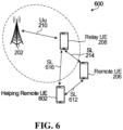
- the example 600 includes multiple out-of-coverage remote UEs 206, 602, and an in-coverage relay UE 208.
- Two relay links are provided for the remote UE 206 in this example: over the sidelink 214 and over the sidelinks 612, 616 through the "helping" remote UE 602.
- the out-of-coverage remote UE 206 transmits data to the helping out-of-coverage remote UE 602 on the sidelink 612, the out-of-coverage remote UE 206 and the out-of-coverage helping remote UE 602 cooperatively transmit the data to the in-coverage relay UE 208, and the in-coverage relay UE relays the data to the gNB 202.
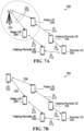
- a similar example 700 is shown, but includes two in-coverage relay UEs 204, 208, multiple out-of-coverage helping remote UEs 704, 708, and a further remote UE 206.
- Two relay links are provided for the remote UE 206 in this example, over the sidelinks 212, 712 through the helping remote UE 704 and over the sidelinks 214, 714 through the helping remote UE 708.
- multiple relay links are formed where one end is a base station, gNB, TRP or other network equipment 202 and the other end is a remote UE 206, which may be considered a destination UE in the context of downlink transmission or a source UE in the context of uplink transmission.
- a gNB 202 sends data to each of the in-coverage relay UEs 204, 208 on a Uu link 210, and the relay UEs relay the data from the gNB to the next helping remote UE 704, 708 on each relay link, over the sidelinks 212, 214.
- there are multiple relay UEs in a relay link and each relay UE relays data to a next relay UE over a sidelink.
- the last relay UE or helping remote UE 704, 708 relays the data on the sidelinks 712, 714 to the out-of-coverage destination remote UE 206.
- the out-of-coverage source remote UE 206 transmits data to nearby helping remote UEs 704, 708 on the sidelinks 712, 714 of each relay link.
- the helping remote UEs 704, 708 relay the data to the next helping remote UE, or to a relay UE 204, 208 in the example shown, on each relay link over the sidelinks 212, 214.
- the last in-coverage relay UE 204, 208 relays the data to the gNB 202 on each relay link over a Uu link 210.
- Fig. 7B is a block diagram of another example communication system illustrating multi-hop UE-to-UE relay links.
- the example 750 is similar to the example 700 in Fig. 7A , but includes a source UE 752 that has sidelinks 754, 756 with the two relay UEs 204, 208, instead of a gNB and Uu links.
- Two multi-hop UE-to-UE relay links are provided for the remote UE 206 in this example, over the sidelinks 754, 212, 712 through the relay UE 204 and the helping remote UE 704, and over the sidelinks 756, 214, 714 through the relay UE 208 and the helping remote UE 708.
- the multiple relay links are formed between two UEs 752, 206. If the UE 752 has data to send to the remote UE 206, then the UE 752 may be considered a source UE and the remote UE 206 may be considered a destination UE. For this direction of transmission, in an embodiment the source UE 752 sends data to each of the relay UEs 204, 208 on a sidelink 754, 756, and the relay UEs relay the data from the source UE 752 to the next helping remote UE 704, 708 on each relay link, over the sidelinks 212, 214. In another embodiment, there are multiple relay UEs in a relay link, and each relay UE relays data to a next relay UE over a sidelink.
- the last relay UE or helping remote UE 704, 708 relays the data on the sidelinks 712, 714 to the destination UE 206.
- the remote UE 206 transmits data to nearby helping remote UEs 704, 708 on the sidelinks 712, 714 of each relay link.
- the helping remote UEs 704, 708 relay the data to the next helping remote UE, or to a relay UE 204, 208 in the example shown, on each relay link over the sidelinks 212, 214.
- the last relay UE 204, 208 relays the data to the UE 752 on each relay link over an sidelink 754, 756.
- Figs. 2 to 7B are intended solely as examples. Other embodiments that involve one or more relay UEs and in-coverage or out-of-coverage remote UEs are possible.
- the present disclosure, and coordination or cooperation between multiple relay links, are not limited only to these examples, or to the particular examples that are used to describe embodiments in further detail below.
- a base station, gNB, or other network equipment configures multiple UE relay links for a remote UE.
- a gNB 202 could configure a first one of the UE relay links as an MRL and configure another, second UE relay link as an SRL.
- the configuration may include an index for each relay link, such as relay link #1 for the first relay link or MRL, relay link #2 for an SRL or second relay link, and so on for any further relay links or SRLs for the same remote UE 206.
- the configuration may also or instead include one or more indices, such as a UE Radio Network Temporary Identifier (RNTI), for any of a relay UE, a helping remote UE, and a remote UE involved in each relay link.
- RNTI UE Radio Network Temporary Identifier
- a relay link may include multiple UE relays.
- a relay link may also or instead include multiple helping remote UEs.
- relay links such as an MRL and any SRLs may have different roles.
- an MRL could carry more information such as control and feedback, while both an MRL and each SRL could carry data.
- the MRL and SRL roles, or more generally roles of different relay links, may be switched or updated between any of the multiple relay links in some embodiments.
- a relay link may be activated or enabled, for example, as part of configuration or by actually transmitting data on the relay link after its configuration.
- Data may be transmitted on a relay link as scheduled or initiated by a gNB, as scheduled or initiated by the remote UE of the MRL, as scheduled or initiated by an MRU, or as scheduled or initiated by a helping remote UE in the MRL, for example.
- a relay link can be disabled by configuration or signaling by one or more of the gNB, an MRU, a helping remote UE in the MRL, and the remote UE.
- a scheduler is used to determine a scheduling strategy among relay links. For example, for diversity or reliability, a best relay link or multiple relay links may be scheduled or otherwise selected to transmit the same data. For higher aggregated data rate multiple relay links may be scheduled or otherwise selected to transmit different data.
- Link scheduling or selection may be based on any of various factors or conditions, such as any one or more of: Quality of Service (QoS) provided by a link, QoS required by a data application, UE Buffer Status Report (BSR) for uplink transmission from the remote UE, and Channel State Information (CSI) for the link.
- QoS Quality of Service
- BSR UE Buffer Status Report
- CSI Channel State Information
- Potential benefits of configuring multiple relay links include improved multiple relay link UE diversity, in that the same data could be transmitted on multiple relay links instead of only over one link, thus providing multi-relay link gain. Improved aggregated throughput and coverage are also potential benefits, in that data can be split and transmitted on multiple relay links to the remote UE in downlink or to the gNB or other network equipment in uplink, and aggregated or combined at the downlink or uplink destination.
- the gNB 202 or the MRU 208 may configure the SRL(s) for relay link cooperation.
- the gNB 202 or the MRU 208 signals the remote UE 206 via the MRL, through sidelinks 214, 714 and the helping remote UE 708 in Fig. 7A , to transmit sidelink discovery signaling, on the sidelink 712 in the example shown.
- the signaling to cause the remote UE 206 to transmit discovery signaling is also referred to herein as a discovery request or discovery request signaling, and may more generally be considered a request to search for other relay links as shown in Fig. 8 .
- the remote UE 206 transmits the discovery signaling at 806, by broadcast or at least over all known sidelinks, for example.
- the discovery signaling could be or include dedicated signals that are used only for the purpose of discovery or generic reference signaling such as Channel State Information-Reference Signal (CSI-RS) or Demodulation Reference Signal (DMRS) for channel measurement or demodulation purposes.
- CSI-RS Channel State Information-Reference Signal
- DMRS Demodulation Reference Signal
- the discovery request could include the configuration of discovery signal transmission such as periodicity or offset of discovery signal transmission or triggering for transmission of aperiodic discovery signaling.
- a component that receives discovery signaling such as the helping remote UE 704 in the example system 700, performs one or more measurements at 808 based on the received discovery signaling, and may exchange information with the remote UE 206 on the sidelink 712, as shown in 810.
- a receiving component may, for example, transmit information indicative of any one or more of: a capability such as relay capability of the component, availability of the component for supporting a relay link for the remote UE 206, and whether the component is currently in-coverage or out-of-coverage. In some embodiments, such information could have been previously exchanged and be stored at the gNB or MRU for determination of an SRL.
- the receiving component which in this example is the helping remote UE 704, passes or reports its measurement(s), and possibly other information, to the gNB 202 as shown at 820, and at 822 the gNB configures or enables an additional relay link as an SRL through the relay UE 204, which can be called a secondary relay UE (SRU).
- SRU secondary relay UE
- the gNB 202 may configure an SRL based on any of a number of factors, such as any one or more of: channel quality of its Uu link with the first relay UE in a candidate SRL such as the relay UE 204; channel quality of a sidelink such as one or both of the sidelink 212 and the sidelink 712 on a candidate SRL; overall channel quality of multiple segments of a relay link or a complete link including a Uu link and at least one sidelink; load of one or more UEs, including either or both of relay UEs or helping UEs on a relay link; capability of one or more UEs, including either or both of relay UEs and helping UEs on a relay link; and availability of one or more UEs, including either or both of relay UEs and helping UEs on a relay link.
- a number of factors such as any one or more of: channel quality of its Uu link with the first relay UE in a candidate SRL such as the relay UE 204; channel quality of a sidelink such as
- Another option involves the receiving component passing or reporting the measurement and possibly other information to the MRU as shown at 830, and the MRU configures or enables the SRL at 832.
- the MRU may apply any of various criteria in selecting between multiple SRLs or determining whether an SRL should be established, including the examples provided above for a gNB.
- the receiving component reports to the remote UE 206 at 840, and the remote UE configures or enables the SRL at 842.
- the remote UE 206 selects and configures the helping remote UE 704 and the relay UE 204 for the SRL.
- the example criteria provided above for a gNB, or others may also or instead be applied by the remote UE 206 in determining whether an SRL should be established and/or in selecting between candidate SRLs.
- the method 800 represents one possible embodiment. Other embodiments may include additional, fewer, or different operations, performed in a similar or different order. For example, some embodiments might not include a discovery procedure that involves discovery request signaling, discovery signaling, measurement, and reporting. A remote UE may already have one or more other configured sidelinks, for example, in which case identifying sidelinks, helping remote UEs, and/or SRUs does not necessarily involve a discovery procedure.
- Either or both of measurement reporting and information exchange may be subject to any of various conditions. For example, there might be no measurement reporting or information exchange if a discovery signaling-based power measurement is below a threshold, to thereby avoid further SRL-related signaling and processing in the case of a sidelink that is not strong enough to support an SRL. Other conditions, such as relay capability, availability, or coverage status (in-coverage or out-of-coverage) may also or instead be applied to measurement reporting or information exchange.
- Either or both of measurement(s) and other information may be collected by one or more of the source UE 752, the MRU 208, the helping remote UE 708, and the remote UE 206 to determine whether an SRL should be configured, or to select between multiple SRLs, for example. SRL establishment and/or selection decisions may be made by any of these components, and any of these components may potentially send configuration signaling to the candidate SRU 204, and the helping remote UE 704 if that UE is to be involved in the SRL, to configure the SRL.
- Figs. 8 to 10 are intended to illustrate some of the many options for coordination or cooperation among multiple relay links. Others are also possible. In general, any of various components may be involved in a discovery procedure or other process to identify candidate SRLs or SRUs; any of various components may be involved in determining whether an SRL should be configured or selecting one or more SRLs and SRUs from multiple candidate SRLs or SRUs; and any of various components may be involved in configuring SRLs. It should therefore be appreciated that there are many different options for setting up multiple relay links, for such features as relay cooperation or switching between multiple relay link cooperation and single relay link transmission.
- Multiple relay links may provide for more flexibility to accommodate different needs. For example, some embodiments may involve switching between a single link and multiple links with relay cooperation.
- RRC Radio Resource Control
- DCI Downlink Control Information
- each relay UE decodes its own Physical Downlink Control Channel (PDCCH), and if a relay UE does not detect and decode its PDCCH then it may not receive and relay data to a remote UE or a gNB.
- PDCCH Physical Downlink Control Channel
- a single DCI is used for all relay UEs.
- the DCI could carry an indication as to which relay UE shall handle the relay transmission.
- a 1-bit field could indicate whether the MRL or the SRL shall be used for relaying the data.
- An implicit indication may use some other type of indication to implicitly indicate whether current configuration is for single relay UE transmission or relay UE cooperation. For example, if DCI indicates two-CW (codeword) transmission, then the first CW transmission may be carried by an MRL and the second CW transmission may be carried by an SRL. As another example, if DCI indicates single-CW transmission, the CW is carried only by the MRL, and no SRL is used.
- Some aspects of the present disclosure relate to scheduling, transmission, data splitting, data aggregation, and data flow.
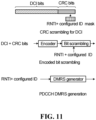
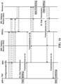
- Fig. 11 illustrates examples of Cyclic Redundancy Check (CRC) scrambling for Downlink Control Information (DCI), encoded bit scrambling for DCI, and Physical Downlink Control Channel (PDCCH) Demodulation Reference Signal (DMRS) generation.
- CRC Cyclic Redundancy Check
- DCI Downlink Control Information
- PDCH Physical Downlink Control Channel
- DMRS Demodulation Reference Signal
- Uu link scheduling has several options, including at least transmission on the Uu link being scheduled by network equipment such as a gNB, or relay UEs in cooperation receiving a single DCI (PDCCH).
- network equipment such as a gNB
- relay UEs in cooperation receiving a single DCI (PDCCH).
- PDCCH DCI
- each relay UE may receive its own DCI (PDCCH).
- An identifier of the remote UE of the relay link such as the remote UE RNTI, may be used for CRC scrambling, encoded bits scrambling, and DMRS generation.
- Another embodiment involves using a relay cooperation RNTI or other identifier for CRC scrambling, encoded bits scrambling, and DMRS generation.
- An identifier of the relay UE for a relay link, such as the relay UE RNTI is used for CRC scrambling, encoded bits scrambling, and DMRS generation in a further embodiment.
- a higher layer configured identifier may be used in conjunction with an identifier such as one of the above identifiers, as shown in Fig. 11 .
- Embodiments for all relay UEs receiving a single DCI include using a remote UE identifier such as an RNTI or a relay cooperation RNTI or other identifier for CRC scrambling, encoded bits scrambling, and DMRS generation. As shown in Fig. 11 , a higher layer configured identifier may be used in conjunction with either of these identifiers.
- identifiers noted above in reference to Figs. 11 and 12 are just examples. Other embodiments may use combinations of these example identifiers and/or use one or more other identifiers.
- CRC scrambling by masking, encoding by an encoder and applying bit scrambling to an encoded output of the encoder, and DMRS generation by a DMRS generator as shown in Figs. 11 and 12 are also illustrative and non-limiting examples.
- the remote UE may detect SCI from the relay UE of each of the relay links for scheduling information, for example, from the MRU and the SRU(s). If the remote UE only detects one SCI, then it could only transmit uplink data in a Physical Shared Sidelink Channel (PSSCH) on the sidelink to that particular relay UE according to the scheduling information indicated in that SCI. If the remote UE detects two SCI(s), including one from a relay UE of each of two relay links respectively, then it could split or duplicate the data and transmit them in a separate PSSCH on sidelink to each relay UE according to the scheduling in the respective SCIs.
- PSSCH Physical Shared Sidelink Channel
- uplink transmission on a sidelink uses one or more pre-configured communication resources, and the remote UE transmits data on the sidelink to the relay UE using the pre-configured resource(s).
- the remote UE could be configured with more than one set of resources on sidelink (e.g., time-frequency resources) and corresponding parameters (e.g., DMRS, Modulation and Coding Scheme (MCS)), including one set for the remote UE to transmit data to each relay UE of each relay link, for example, one set of resources for the remote UE to transmit data to the MRU of the MRL and one set of resources for the remote UE to transmit data to the SRU of an SRL.
- DMRS Modulation and Coding Scheme
- Option 1/2 and Option 3 for downlink in Fig. 13 are similar to Option 1/2 and Option 3 for uplink, except that each relay UE transmits SCI and data both in the downlink direction to the remote UE.
- the remote UE could be configured with more than one set of resources on sidelink (e.g., time-frequency resources) and corresponding parameters (e.g., DMRS, MCS), including one set for each relay UE of each relay link to transmit data to the remote UE, for example, one set of resources for the MRU of the MRL to transmit data to the remote UE and one set of resources for the SRU of an SRL to transmit data to the remote UE.
- These sets of resources could be orthogonal in one or more of time domain, frequency domain, and code domain or they could overlap or partially overlap while a DMRS that is configured could still be orthogonal.
- the remote UE could blindly detect the data transmission on each set of resources on sidelink and determine whether there is data transmitted from the corresponding relay UE to the remote UE. If the remote UE detects data transmission, then it can try to decode the data transmission.
- an example of downlink transmission flow in the example system 200 in Fig. 2 involves a gNB 202 scheduling Uu link 210 and sidelink 212, 214 transmission of downlink data, or the sidelink transmissions using one or more pre-configured communication resources.
- the gNB 202 sends a separate PDCCH and PDSCH over the Uu link 210 for each of the two relay links to the relay UEs 204, 208.
- the PDCCH for each relay UE 204, 208 is scrambled by the RNTI of that relay UE, and a field in DCI can be used to indicate a destination identifier of the remote UE 206.
- the PDSCH for each relay UE 204, 208 is also scrambled by the RNTI of that relay UE.
- Each relay UE 204, 208 then relays data to the remote UE 206 on its sidelink 212, 214 with the remote UE, in a separate PSSCH that is scrambled by remote UE ID.
- the remote UE pass its Scheduling Request (SR) or BSR to the gNB 202, through one of the relay links and a relay UE 204, 208 for example, and the gNB 202 schedules Uu link and sidelink transmission of uplink data.
- the sidelink transmission uses one or more pre-configured communication resources.
- the remote UE transmits data on the sidelinks 212, 214, in a separate PSSCH, to each relay UE 204, 208.
- the PSSCH may be scrambled by a remote UE ID such as an RNTI.
- Each relay UE 204, 208 then relays the data in a Physical Uplink Shared Channel (PUSCH) to the gNB 202 on a Uu link 210.
- PUSCH Physical Uplink Shared Channel
- Each PUSCH is scrambled by a relay UE ID such as an RNTI in some embodiments.
- RVs Redundancy Versions
- the association of relay link and RV can be semi-statically configured, in RRC signaling for example, or dynamically indicated, in DCI for example.
- uplink and downlink transmission are just illustrative examples of uplink and downlink transmission. Other embodiments are also possible. For example, transmission between a remote UE and another UE over UE-to-UE relay links as shown by way of example in Fig. 7B may be substantially similar uplink and downlink transmission between a network device and a remote UE.
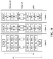
- Fig. 14 is a block diagram illustrating example data splitting options for relay link coordination. Using multiple relay links to transmit data involves data splitting for transmission of different data, or data duplication for transmission of the same data, over multiple relay links. Data duplication may be considered a special case of data splitting, in which the same data are duplicated for transmission over two paths. Fig. 14 illustrates some general options.
- a receiver which may be the remote UE or network equipment such as a gNB in some embodiments, or one of two UEs in UE-to-UE relay link embodiments, data can be aggregated according to where the data splitting or duplication is implemented at the transmitter.
- Fig. 14 is an example, and other embodiments may be implemented in a similar or different manner, in similar or different architectures.
- Fig. 15 is a signal flow diagram illustrating examples for configuring a relay link, which is an MRL in the example shown, and a discovery procedure.
- Fig. 16 is a signal flow diagram illustrating examples for configuring a further relay link, which is an SRL in the example shown, and relay link transmissions including downlink and uplink transmissions on either or both of MRL and SRL.
- Figs. 15 and 16 are intended to illustrate various scenarios.
- a helping remote UE may or may not be involved in a relay link.
- a gNB or TRP may not be involved in a relay link in the case of UE-to-UE relay links, shown by way of example in Fig. 7B . In such links, features that are shown in Figs.
- a gNB or TRP may apply to a UE such as the UE 752 in Fig. 7B .
- MRL, MRU, SRL, and SRU are shown in and described with reference to Figs. 15 and 16 solely as a convenience to distinguish different relay links and components of such links from each other. More generally, primary or major relay links or components and similarly secondary relay links or components may be considered examples of different, first and second for example, relay links or components.
- configuration signaling may be transmitted from network equipment such as a gNB or a TRP to a helping remote UE in the MRL if that helping remote UE is in coverage, as shown by the second solid line at the top left of Fig. 15 , or transmitted to an MRU and relayed to the MRL helping remote UE by the MRU, as shown by the dashed lines below that solid line.
- Different solid lines may also represent options rather than features that may be implemented in every embodiment.
- One or more discovery requests may be transmitted by the gNB or TRP in Fig. 15 , for example, but not all, or even any, of the discovery requests illustrated in Fig. 15 need necessarily be transmitted by the gNB or TRP. As noted above, discovery is an optional procedure that might not be performed at all.
- relay UEs may perform operations such as data processing and/or decoding on data that is received over a Uu link before that data is relayed to the remote UE or to a helping remote UE.
- relay UEs may perform operations such as data processing and/or decoding on data that is received over a sidelink link before that data is relayed to the gNB or TRP over a Uu link.
- a component may send discovery signaling without necessarily first receiving a discovery request, such as when MRL configuration has been completed and the MRL has been set up. Therefore, communicating signaling as referenced above may involve transmitting discovery signaling that enables identification of a candidate relay link for configuration as the SRL, without necessarily first receiving other signaling. For example, any one or more of the MRU 208, the helping remote UE 708, and the remote UE 206 may detect that the MRL has been configured, and then broadcast or otherwise transmit discovery signaling without having first received a discovery request.
- components that may receive discovery signaling include any one or more of the MRU 208, one or more helping remote UEs such as 708, the remote UE 206, the candidate SRU 204, and one or more candidate helping remote UEs such as 704. Any of these components that receives discovery signaling may perform one or more measurements, and possibly make a decision based on the measurement(s). The measurement(s), a decision based on the measurement(s), or both, may be reported or fed back to any other component, including the network equipment 202, or a UE such as the UE 752 ( Fig. 7B ) in the case of UE-to-UE relay links.
- Configuration signaling may be generated by the network equipment 202, or a UE such as the UE 752 ( Fig. 7B ) in the case of UE-to-UE relay links, and relayed by one or more of these other components.
- configuration signaling need not necessarily originate only from the network equipment 202, or a UE such as the UE 752 ( Fig. 7B ) in the case of UE-to-UE relay links.
- the MRU 208 may generate and transmit configuration signaling.
- a method may involve coordinating communications with the UE over the MRL and the SRL.
- the network equipment 202 and the remote UE 206 may communicate with each other over both the MRL through the MRU 208 and the helping remote UE 708 and the SRL through the SRU 204 and the helping remote UE 704.
- UEs may also or instead communicate with each other through relay links as shown by way of example in Fig. 7B .
- Coordinating communications through an MRL and an SRL may involve, for example, determining a data split for communications with the remote UE over the MRL and the SRL.
- One or more of the following may be performed in some embodiments: transmitting signaling indicative of the data split to one or more components involved in the MRL; transmitting signaling indicative of the data split to one or more components involved in the SRL; splitting data, such as received data, in accordance with the data split for transmission over the MRL and the SRL; and aggregating received data in accordance with the data split for transmission over the MRL and the SRL.
- the network equipment 202 may determine how data should be split between the MRL and the SRL, and transmit signaling indicative of this data split to at least the remote UE 206 so that the remote UE is able to aggregate received data in accordance with the data split.
- the MRU 208 may determine and signal the data split to one or more other components such as the network equipment 202, or a UE such as the UE 752 ( Fig. 7B ) in the case of UE-to-UE relay links, and the remote UE 206.
- a data split may also or instead be determined by the remote UE 206 and signaled to the network equipment 202, or a UE such as the UE 752 ( Fig. 7B ) in the case of UE-to-UE relay links.
- Actual splitting and aggregation of data may also be handled by any of various components.
- data splitting is handled by the network equipment 202 and data aggregation is handled by the remote UE 206 for downlink transmission
- for uplink transmission data splitting is handled by the remote UE and data aggregation is handled by the network equipment.
- Other embodiments are also possible.
- data splitting for downlink transmission and data aggregation for uplink transmission may be handled by the relay UE 208.
- Fig. 7B in which data splitting for transmission toward the remote UE 206 and data aggregation for transmission of data in the opposite direction may be handled by the UE 752.
- Signaling indicative of a data split may be or include SCI, for example, in which case the splitting and aggregating are in accordance with received SCI.
- pre-configured communication resources are used.
- Data splitting may then involve, for example, splitting data, such as received data, for transmission over pre-configured communication resources associated with the primary relay link and the SRL, and the received data for the aggregating may include data received over pre-configured communication resources associated with the primary relay link and the SRL.
- SCI and pre-configured resource examples are discussed in further detail at least above with reference to Fig. 13 .
- Some embodiments support switching between multi-link and single-link communications. For example, coordinating communications over an MRL and an SRL may involve determining whether communications with the remote UE 206 over both the MRL and the SRL are to be maintained. Multi-link communications may no longer be needed to support a higher data rate for communications with the remote UE 206, for example. Communications with the UE over only the MRL may then be enabled responsive to determining that communications over both the MRL and the SRL are not to be maintained. This is an example of multi-link to single-link switching.
- coordinating communications over the MRL and the SRL may involve determining whether communications with the remote UE 206 over only the MRL are to be maintained, and enabling communications with the remote UE over both the MRL and an SRL responsive to determining that communications with the UE over only the primary relay link are not to be maintained. This may involve reconfiguring the same SRL that was previously used or configuring a further SRL. Thus, when switching to multi-link communications, an SRL may or may not be the same as an SRL that was previously used.
- An MRU may be reconfigured as an SRU, and an SRU may be reconfigured as an MRU for example.
- Such reconfiguration may be performed by network equipment in some embodiments, or by a UE such as the UE 752 ( Fig. 7B ) in the case of UE-to-UE relay links.
- any one or more of various components may be involved in operations disclosed herein.
- any one or more of the following may be handled by the MRU 208 in Fig. 7A : determining a data split, determining whether communications with the remote UE 206 over the MRL and the SRL are to be maintained, enabling communications with the remote UE over only the MRL responsive to determining that communications with the remote UE over the MRL and the SRL are not to be maintained, determining whether communications with the remote UE over only the MRL are to be maintained, enabling communications with the remote UE over the MRL and the SRL or a further SRL responsive to determining that communications with the remote UE over only the MRL are not to be maintained, and performing one or more of: transmitting signaling indicative of the data split to one or more components involved in the MRL; transmitting signaling indicative of the data split to one or more components involved in the SRL; splitting data, such as received data, in accordance with the data split for transmission over the MRL and the SRL; and aggregating received data in accordance with the data split
- coordinating communications over the MRL and the SRL may involve the SRU performing one or more of: receiving signaling indicative of a data split determined for communications with the remote UE 206 over the MRL and the SRL; splitting data, such as received data, in accordance with the data split for transmission over the SRL; disabling communications with the remote UE over the SRL responsive to signaling received from the MRU 208, and enabling communications with the remote UE over the SRL responsive to signaling received from the MRU.
- coordinating communications may involve the remote UE performing such actions as one or more of: receiving signaling indicative of a data split determined for communications with the UE over the MRL and the SRL; splitting data, in accordance with the data split, for transmission over the MRL and the SRL; aggregating, in accordance with the data split, data received over the MRL and the SRL; disabling communications over the SRL responsive to signaling received from the MRU 208, and enabling communications with the remote UE over the SRL or a further SRL responsive to signaling received from the MRU.
- the MRL includes at least one relay UE 208 that is within a coverage area of the wireless communication network, and the remote UE 206 is outside the coverage area of the wireless communication network.
- the MRL may include a helping remote UE such as 708 that is outside the coverage area of the wireless communication network and is in communication with the relay UE 208 and the remote UE 206.
- an SRL may include at least one secondary relay UE 204 that is within the coverage area of the wireless communication network, with the remote UE 206 being outside the coverage area, and in some embodiments a secondary helping remote UE 704 that is outside the coverage area and is in communication with the secondary relay UE and the remote UE.
- Another method involves receiving, by a component that is involved in an MRL for a UE, such as a relay link between a remote UE and a wireless communication network, signaling indicative of a measurement performed by a first UE for a direct wireless communication link such as a sidelink between the first UE and a second UE.
- a component that is involved in an MRL for a UE such as a relay link between a remote UE and a wireless communication network
- signaling indicative of a measurement performed by a first UE for a direct wireless communication link such as a sidelink between the first UE and a second UE.
- any one or more of the network equipment 202, the MRU 208, the helping remote UE 708, and the remote UE 206 may receive measurement signaling, and possibly other information related to a direct wireless communication link such as a sidelink.
- a UE such as the UE 752 ( Fig. 7B ) in the case of UE-to-UE relay links may also or instead receive measurement signaling
- Configuration signaling to configure the SRL is transmitted responsive to determining that the SRL should be established through the direct wireless communication link.
- the remote UE 206 may also be involved in a sidelink that is part of a candidate SRL.
- the remote UE 206 performs a measurement for the sidelink 712.
- the remote UE 206 is the above-referenced first UE that performs the measurement.
- the helping remote UE 704 performs a measurement for the sidelink 712, in which case the helping remote UE 704 is the above-referenced first UE that performs the measurement and the remote UE 206 is the above-referenced the second UE that is involved in the sidelink for which the measurement is performed.
- the remote UE 206 may be the above-referenced first UE or the above-referenced second UE.
- a method may include transmitting, by the component that is involved in the primary relay link and receives the measurement signaling, further signaling to enable the first UE to perform the measurement.
- This further signaling may be or include discovery signaling for example.
- Some embodiments include transmitting, by the component that is involved in the primary relay link and receives the measurement signaling, further signaling to cause the second UE to transmit to the first UE signaling to enable the first UE to perform the measurement.
- a discovery request may be transmitted by the remote UE 206 to the helping remote UE 1004 to cause the helping remote UE 1004 to transmit discovery signaling to the relay UE 204, which in turn performs a measurement for the sidelink 1012 and transmits measurement signaling back to the remote UE 206.
- Another method consistent with the present disclosure relates to switching types or roles of relay links, such as MRL / SRL roles.
- a method may involve configuring an MRL to carry data and one or both of control and feedback information between a UE and a wireless communication network; configuring an SRL to carry data between the UE and the wireless communication network; and, responsive to a relay link role switch condition, reconfiguring the SRL as a new MRL to carry data and one or both of control and feedback information between the UE and the wireless communication network and reconfiguring the MRL as a new SRL to carry data between the UE and the wireless communication network.
- Data and one or both of control and feedback information may be carried between a UE and a wireless communication network in some embodiments, or otherwise communicated with a UE as in the case of UE-to-UE relay links for example.
- Embodiments are described above primarily in the context of example methods. Other embodiments are also possible.
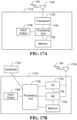
- FIG. 17A and 17B illustrate example devices that may implement the methods and teachings according to this disclosure.
- Fig. 17A illustrates an example ED 1710
- Fig. 17B illustrates an example base station 1770. These components could be used in the system 100 ( Fig. 1 ) or in any other suitable system.
- the ED 1710 includes at least one processing unit 1700.
- the processing unit 1700 implements various processing operations of the ED 1710.
- the processing unit 1700 could perform signal coding, data processing, power control, input processing, output processing, or any other functionality enabling the ED 1710 to operate in a communication system.
- the processing unit 1700 may also be configured to implement some or all of the functionality or embodiments described in more detail herein.
- Each processing unit 1700 includes any suitable processing or computing device configured to perform one or more operations.
- Each processing unit 1700 could, for example, include a microprocessor, microcontroller, digital signal processor, field programmable gate array, or application specific integrated circuit.
- the ED 1710 also includes at least one transceiver 1702.
- the transceiver 1702 is configured to modulate data or other content for transmission by at least one antenna or NIC (Network Interface Controller) 1704.
- the transceiver 1702 is also configured to demodulate data or other content received by the at least one antenna 1704.
- Each transceiver 1702 includes any suitable structure for generating signals for wireless transmission and/or processing signals received wirelessly or by wire.
- Each antenna 1704 includes any suitable structure for transmitting and/or receiving wireless signals.
- One or multiple transceivers 1702 could be used in the ED 1710, and one or multiple antennas 1704 could be used in the ED 1710.
- a transceiver 1702 could be implemented using at least one transmitter and at least one separate receiver.
- the ED 1710 further includes one or more input/output devices 1706 or interfaces.
- the input/output devices 1706 facilitate interaction with a user or other devices (network communications) in the network.
- Each input/output device 1706 includes any suitable structure for providing information to or receiving/providing information from a user, such as a speaker, microphone, keypad, keyboard, display, or touch screen, including network interface communications.
- the ED 1710 includes at least one memory 1708.
- the memory 1708 stores instructions and data used, generated, or collected by the ED 1710.
- the memory 1708 could store software instructions or modules configured to implement some or all of the functionality or embodiments described above and that are executed by the processing unit(s) 1700.
- Each memory 1708 includes any suitable volatile and/or non-volatile storage and retrieval device(s). Any suitable type of memory may be used, such as random access memory (RAM), read only memory (ROM), hard disk, optical disc, subscriber identity module (SIM) card, memory stick, secure digital (SD) memory card, and the like.
- RAM random access memory
- ROM read only memory
- SIM subscriber identity module
- SD secure digital
- the base station 1770 includes at least one processing unit 1750, at least one transmitter 1752, at least one receiver 1754, one or more antennas 1756, at least one memory 1758, and one or more input/output devices or interfaces 1766.
- a transceiver not shown, may be used instead of the transmitter 1752 and receiver 1754.
- a scheduler 1753 may be coupled to the processing unit 1750. The scheduler 1753 may be included within or operated separately from the base station 1770.
- the processing unit 1750 implements various processing operations of the base station 1770, such as signal coding, data processing, power control, input processing, output processing, or any other functionality.
- the processing unit 1750 can also be configured to implement some or all of the functionality or embodiments described in more detail herein.
- Each processing unit 1750 includes any suitable processing or computing device configured to perform one or more operations.
- Each processing unit 1750 could, for example, include a microprocessor, microcontroller, digital signal processor, field programmable gate array, or application specific integrated circuit.
- Each transmitter 1752 includes any suitable structure for generating signals for wireless transmission to one or more EDs or other devices.
- Each receiver 1754 includes any suitable structure for processing signals received wirelessly or by wire from one or more EDs or other devices. Although shown as separate components, at least one transmitter 1752 and at least one receiver 1754 could be combined into a transceiver.
- Each antenna 1756 includes any suitable structure for transmitting, receiving, or both transmitting and receiving wireless signals. While a common antenna 1756 is shown here as being coupled to both the transmitter 1752 and the receiver 1754, one or more antennas 1756 could be coupled to the transmitter(s) 1752, and one or more separate antennas 1756 could be coupled to the receiver(s) 1754.
- Each memory 1758 includes any suitable volatile and/or non-volatile storage and retrieval device(s) such as those described above in connection to the ED 1710.
- the memory 1758 stores instructions and data used, generated, or collected by the base station 1770.
- the memory 1758 could store software instructions or modules configured to implement some or all of the functionality or embodiments described herein and that are executed by the processing unit(s) 1750.
- Each input/output device 1766 facilitates interaction with a user or other devices (network communications) in the network.
- Each input/output device 1766 includes any suitable structure for providing information to or receiving/providing information from a user, including network interface communications.
- a signal may be transmitted by a transmitting unit or a transmitting module.
- a signal may be received by a receiving unit or a receiving module.
- a signal may be processed by a processing unit or a processing module.
- Other steps may be performed by these or other modules.
- the respective units or modules may be implemented using hardware, components that execute software, or a combination thereof.
- one or more of the units or modules may be or include one or more integrated circuits, such as field programmable gate arrays (FPGAs) or application-specific integrated circuits (ASICs).
- FPGAs field programmable gate arrays
- ASICs application-specific integrated circuits
- any of various types of memory devices could be implemented.
- an apparatus may include a processor and a non-transitory computer readable storage medium, such as the processing unit 1700, 1750 and memory 1708, 1758 in Fig. 17A or Fig. 17B .
- Such an apparatus may be a UE, including a relay UE, a source UE, a destination UE, a helping remote UE, or a remote UE.
- network equipment which may be a gNB, a TRP, a base station, or any other type of network equipment referenced herein.
- the storage medium stores programming for execution by the processor, and the programming includes instructions to perform a method as disclosed herein. For example, the instructions, when executed by a processor, may cause the processor to perform any of various operations.
- Another embodiment relates to a computer program product that includes a non-transitory computer readable storage medium storing programming.
- the programming includes instructions to perform a method as disclosed herein.
- the programming includes instructions to cause a processor to coordinate, with a primary relay link between a UE and a wireless communication network, configuration of a secondary relay link between the UE and the wireless communication network; and to communicate signaling to enable configuration of the secondary relay link in accordance with the coordinating.
- the programming includes instructions to cause a processor to perform a method that involves coordinating, with a first relay link for a UE in a wireless communication network, configuration of a second relay link for the UE; and communicating signaling to enable configuration of the second relay link in accordance with the coordinating.
- the first relay link and the second relay link may be or include relay links between the UE and a network device in the wireless communication network, or relay links between the UE and another UE.
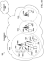
- Fig. 18 is a block diagram illustrating an example of a telecommunications network 1800 according to one embodiment.
- the telecommunications network 1800 includes a core network 1802 and an access network 1806.
- the access network 1806 serves a plurality of UEs 1804a, 1804b, 1804c, 1804d, 1804e, 1804f, 1804g, 1804h, and 1804i.
- the access network 1806 is an Evolved Universal Terrestrial Access (E-UTRA) network in some embodiments.
- E-UTRA Evolved Universal Terrestrial Access
- Another example of an access network 1806 is a cloud access network (C-RAN).
- the access network 1806 includes a plurality of BSs 1808a, 1808b, and 1808c.
- the BSs 1808a-c each provide a respective wireless coverage area 1810a, 1810b, and 1810c, also referred to as a cell.
- Each of the BSs 1808a-c could be implemented using a radio transceiver, one or more antennas, and associated processing circuitry, such as antenna radio frequency (RF) circuitry, one or more analog-to-digital converters, one or more digital-to-analog converters, etc.
- RF radio frequency
- the BSs 1808a-c are each connected to the core network 1802, either directly or through one or more central processing hubs, such as servers.
- the BSs 1808a-c could serve as a gateway between the wireline and wireless portion of the access network 1806.
- Each one of BSs 1808a-c may instead be referred to as a base transceiver station, a radio BS, a network node, a transmit node, a transmit point, a Node B, an eNode B, a remote radio head (RRH), or otherwise, depending upon the implementation.
- a base transceiver station a radio BS
- a network node a transmit node
- a transmit point a transmit point
- Node B an eNode B
- RRH remote radio head
- the plurality of UEs 1804a-i access the telecommunications network 1800 using the access network 1806 by wirelessly communicating with one or more of the BSs 1808a-c.
- UEs 1804a-d are in close proximity to each other. Although the UEs 1804a-d can each wirelessly communicate with the BS 1808a, they can also directly communicate with each other, as represented at 1816.
- the communications represented at 1816 are direct communications between UEs, such as sidelink communications as disclosed herein, that do not go through an access network component, such as a BS.
- UE to UE communications 1816 are directly between the UEs 1804a-d and are not routed through the BS 1808a, or any other part of the access network 1806. Communications 1816 may also be referred to as lateral communications.
- UE to UE communications use a sidelink channel and a sidelink air interface.
- an access communication occurs over an access channel, which can be a uplink or downlink channel, and an access communication uses a radio access communication interface, such as a cellular radio access air interface.
- Access and sidelink air interfaces may use different transmission formats, such as different waveforms, different multiple access schemes, or different radio access technologies.
- radio access technologies that could be used by an access air interface or a sidelink air interface are: Long Term Evolution (LTE), LTE License Assisted Access (LTE-LAA), and WiFi.
- the UEs 1804a-d may be able to assist with wireless communications between the UEs 1804a-d and the BS 1808a.
- UE 1804c fails to correctly decode a packet received from the BS 1808a but UE 1804d is able to receive and correctly decode the packet from the BS 1808a, then UE 1804d could directly transmit the decoded packet to UE 1804c using sidelink communications 1816.
- UE 1804c moves out of wireless coverage area 1810c, such that UE 1804c can no longer wirelessly communicate with the BS 1808a, then UE 1804b could forward messages between the UE 1804c and the BS 1808a.
- UE 1804a and UE 1804c could both receive a signal transmitted from the BS 1808a that carries a packet meant for UE 1804c.
- UE 1804a may then transmit to UE 1804c, via sidelink communications 1816, the signal as received by UE 1804a.
- UE 1804c may then use the information received from UE 1804a to help decode the packet from the BS 1808a.
- capacity or coverage may be enhanced through the assistance of one or more of the UEs 1804a, 1804b, and 1804d.
- the UEs 1804a-d form a UE group 1820 in some embodiments. It should be noted, however, that relay links as disclosed herein are not dependent upon UE groups.
- the access network 1806 could assign a group identifier (ID) to the UE group 1820.
- the UE group ID may allow the access network 1806 to address the UE group 1820 as a whole and distinguish the UE group 1820 from other UE groups.
- the UE group ID may also be used to broadcast information within the UE group; that is, address all other UEs within the UE group 1820.
- the UE group 1820 may form a logical or virtual device mesh in which the members of the UE group 1820 communicate amongst themselves using UE communications over a sidelink air interface, but the UE group 1820 as a whole acts as a single distributed virtual transceiver with respect to the access network 1806.
- the UE group ID may be a group radio network temporary identifier (G-RNTI), for example.
- G-RNTI group radio network temporary identifier
- the other UEs 1804a, 1804b, and 1804d in the group 1820 may be considered candidates to be a relay UE or a helping UE.
- the subset of UEs in that actually assist the UE 1804c form a cooperation active set or a cooperation group.
- the cooperation active set may be dynamically selected to assist the UE 1804c.
- UEs 1804a, 1804b, and 1804d form a cooperation candidate set. If UEs 1804a and 1804b actually assist the UE 1804c, then the UEs 1804a and 1804b form the cooperation active set. As UEs 1804a-d move around, some may leave the UE group 1820. UE movement may also or instead result in other UEs joining the UE group 1820. Therefore, the cooperation candidate set may change over time. For example, the cooperation candidate set may change semi-statically.
- the UE group 1820 may also be terminated by the network 1806, for example, if the network determines that there is no longer a need or opportunity for the UE group 1820 to provide assistance in wireless communication between the BS 908a and members of the UE group 1820.
- UEs 1804e and 1804f in Fig. 18 form another UE group 1822.
- Fig. 19 is a block diagram illustrating an example of a network 1952 serving two UEs 1954a and 1954b, according to one embodiment.
- the network 1952 may be the access network 1806 from Fig. 18
- the two UEs 1954a and 1954b may be two of the four UEs 1804a-d in Fig. 18
- the UEs 1954a and 1954b may be UEs 1804e and 1804f in Fig. 18 .
- Fig. 19 more generally this need not be the case, which is why different reference numerals are used in Fig. 19 .
- the network 1952 includes a BS 1956 and a managing module 1958.
- the managing module 1958 instructs the BS 1956 to perform actions.
- the managing module 1958 is illustrated as physically separate from the BS 1956 and coupled to the BS 1956 via a communication link 1960.
- the managing module 1958 may be part of a server in the network 1952.
- the managing module 1958 may be part of the BS 1956.
- the managing module 1958 includes a processor 1962, a memory 1964, and a communication module 1966.
- the communication module 1966 is implemented by the processor 1962 when the processor 1962 accesses and executes a series of instructions stored in the memory 1964, the instructions defining the actions of the communication module 1966.
- the communication module 1966 causes the BS 1956 to perform the actions described herein so that the network 1952 can establish, coordinate, instruct, or control relay, and possibly perform such operations in respect of UE groups.
- the communication module 1966 may be implemented using dedicated circuitry, such as an application specific integrated circuit (ASIC) or a programmed field programmable gate array (FPGA).
- ASIC application specific integrated circuit
- FPGA programmed field programmable gate array
- the UE 1954a includes a communication subsystem 1970a, two antennas 1972a and 1974a, a processor 1976a, and a memory 1978a.
- the UE 1954a also includes a communication module 1980a.
- the communication module 1980a is implemented by the processor 1976a when the processor 1976a accesses and executes a series of instructions stored in the memory 1978a, the instructions defining the actions of the communication module 1980a.
- the communication module 1980a causes the UE 1954a to perform actions described herein in relation to one or more of a relay UE, a helping UE, and a remote UE.
- the module 1980a may be implemented by dedicated circuitry, such as an ASIC or an FPGA.
- the communication subsystem 1970a includes processing circuitry, transmit circuitry, and receive circuitry for sending messages from and receiving messages at the UE 1954a. Although one communication subsystem 1970a is illustrated, the communication subsystem 1970a may be multiple communication subsystems.
- Antenna 1972a transmits wireless communication signals to, and receives wireless communications signals from, the BS 1956.
- Antenna 1974a transmits sidelink communication signals to, and receives sidelink communication signals from, other UEs, including UE 1954b.
- SL communications could be over Wi-Fi, in which case the antenna 1974a may be a Wi-Fi antenna.
- the sidelink communications could be over Bluetooth TM , in which case the antenna 1974a may be a Bluetooth TM antenna.
- Sidelink communications could also or instead be over licensed or unlicensed spectrum.
- the UE 1954b includes the same components described above with respect to the UE 1954a. That is, UE 1954b includes communication subsystem 1970b, antennas 1972b and 1974b, processor 1976b, memory 1978b, and communication module 1980b.
- a UE includes a processor, such as 1976a, 1976b in Fig. 19 , and a non-transitory computer readable storage medium, such as 1978a, 1978b in Fig. 19 , storing programming for execution by the processor.
- a non-transitory computer readable storage medium could also or instead be provided separately, as a computer program product. Examples are provided elsewhere herein.
- the present disclosure proposes multiple relay link configuration embodiments that may be useful to improve relay performance for a remote UE, including a number of scenarios for both in-coverage and out-of-coverage cases, with relay link coordination or cooperation.
- an MRL may be set up first and then used to add one or more SRLs by signaling one or more of the MRL remote UE, another relay UE, and one or more other components. Such component(s) may be signaled to cause such operations as one or more of transmission of discovery signaling and measurement feedback to be performed, for example.
- One or more of the MRL remote UE, relay UE(s), and helping UE(s) may also or instead be configured to transmit discovery signaling and have one or more other remote UE(s) or relay UE(s) perform one or more measurements.
- One or more of the MRL remote UE and relay UE(s) could negotiate with one or more other remote UE(s) or relay UE(s) to set up an SRL, or SRL configuration may be handled by network equipment such as a gNB or TRP.
- Options for switching between single relay transmission and multiple relay link cooperation are also described, and may include semi-static configuration or dynamic signaling, for example. Such switching may provide flexibility, for such purposes as accommodating different needs between robustness and performance.
- any module, component, or device exemplified herein that executes instructions may include or otherwise have access to a non-transitory computer readable or processor readable storage medium or media for storage of information, such as computer readable or processor readable instructions, data structures, program modules, and/or other data.
- non-transitory computer readable or processor readable storage media includes magnetic cassettes, magnetic tape, magnetic disk storage or other magnetic storage devices, optical disks such as compact disc read-only memory (CD-ROM), digital video discs or digital versatile disc (DVDs), Blu-ray Disc TM , or other optical storage, volatile and non-volatile, removable and nonremovable media implemented in any method or technology, random-access memory (RAM), read-only memory (ROM), electrically erasable programmable read-only memory (EEPROM), flash memory or other memory technology. Any such non-transitory computer readable or processor readable storage media may be part of a device or accessible or connectable thereto. Any application or module herein described may be implemented using instructions that are readable and executable by a computer or processor may be stored or otherwise held by such non-transitory computer readable or processor readable storage media.
- RAM random-access memory
- ROM read-only memory
- EEPROM electrically erasable programmable read-only memory
- flash memory or other memory technology
Landscapes
- Engineering & Computer Science (AREA)
- Computer Networks & Wireless Communication (AREA)
- Signal Processing (AREA)
- Databases & Information Systems (AREA)
- Mobile Radio Communication Systems (AREA)
Claims (13)
- Verfahren, das durch eine Basisstation, einen gNodeB oder eine andere Netzwerkeinrichtung (202) durchgeführt wird, zum Konfigurieren mehrerer Relay-Verbindungen einer Benutzereinrichtung, UE, für eine UE (206), das umfasst:Koordinieren, mit einer ersten Relay-Verbindung für eine Benutzereinrichtung, UE, in einem Drahtloskommunikationsnetzwerk, einer Konfiguration einer zweiten Relay-Verbindung für die UE;Kommunizieren einer Signalisierung, um die Konfiguration der zweiten Relay-Verbindung gemäß dem Koordinieren zu ermöglichen,wobei die erste Relay-Verbindung eine erste Relay-UE (204) umfasst und die zweite Relay-Verbindung eine zweite Relay-UE (208) umfasst,wobei sich die erste Relay-UE (204) innerhalb eines Abdeckungsbereichs des Drahtloskommunikationsnetzwerks befindet und wobei sich die UE (206) außerhalb des Abdeckungsbereichs des Drahtloskommunikationsnetzwerks befindet; unddadurch gekennzeichnet, dass:
die erste Relay-Verbindung ferner eine helfende Remote-UE (704), die sich außerhalb des Abdeckungsbereichs des Drahtloskommunikationsnetzwerks befindet und mit der Relay-UE (204) und der UE (206) in Kommunikation steht, umfasst. - Verfahren nach Anspruch 1,wobei das Koordinieren ein Bestimmen umfasst, ob eine zweite Relay-Verbindungsaufbaubedingung, die mit der ersten Relay-Verbindung verknüpft ist, erfüllt ist,wobei das Kommunizieren das Kommunizieren der Signalisierung, die sich auf das Bestimmen bezieht, dass die zweite Relay-Verbindungsaufbaubedingung erfüllt ist, umfasst.
- Verfahren nach Anspruch 1, wobei das Kommunizieren das Kommunizieren der Signalisierung von einer Komponente, die an der ersten Relay-Verbindung beteiligt ist, an eine andere Komponente umfasst, um die andere Komponente zu veranlassen, eine Erkennungssignalisierung, die eine Identifizierung einer Kandidaten-Relay-Verbindung für die Konfiguration als die zweite Relay-Verbindung ermöglicht, zu übertragen.
- Verfahren nach Anspruch 1, wobei das Kommunizieren das Übertragen der Erkennungssignalisierung, die die Identifizierung einer Kandidaten-Relay-Verbindung für die Konfiguration als die zweite Relay-Verbindung ermöglicht, umfasst.
- Verfahren nach Anspruch 1,wobei das Koordinieren ein Empfangen der Signalisierung, die mit der ersten Relay-Verbindung verknüpft ist, umfasst,wobei das Kommunizieren das Kommunizieren der Signalisierung umfasst, um die Konfiguration der zweiten Relay-Verbindung als Reaktion auf das Empfangen der Signalisierung, die mit der ersten Relay-Verbindung verknüpft ist, zu ermöglichen.
- Verfahren nach Anspruch 1, wobei das Koordinieren das Empfangen der Signalisierung, die eine Kandidaten-Relay-Verbindung für die Konfiguration als die zweite Relay-Verbindung angibt, umfasst.
- Verfahren nach Anspruch 1, wobei das Kommunizieren das Übertragen, von einer Komponente, die an der ersten Relay-Verbindung beteiligt ist, einer Konfigurationssignalisierung, um die zweite Relay-Verbindung zu konfigurieren, umfasst.
- Verfahren nach Anspruch 1, das ferner umfasst:
Bestimmen einer Datenaufteilung für die Kommunikation mit der UE über die erste Relay-Verbindung und die zweite Relay-Verbindung. - Verfahren nach einem der vorstehenden Ansprüche, wobei sich die zweite Relay-UE (208) innerhalb des Abdeckungsbereichs des Drahtloskommunikationsnetzwerks befindet.
- Verfahren nach Anspruch 9, wobei die zweite Relay-Verbindung ferner eine zweite helfende Remote-UE (708), die sich außerhalb des Abdeckungsbereichs des Drahtloskommunikationsnetzwerks befindet und mit der zweiten Relay-UE (208) der zweiten Relay-Verbindung und der UE (206) in Kommunikation steht, umfasst.
- Verfahren nach einem der Ansprüche 1 bis 10, wobei die erste Relay-Verbindung und die zweite Relay-Verbindung Relay-Verbindungen zwischen der UE und einem Netzwerkgerät in dem Drahtloskommunikationsnetzwerk oder Relay-Verbindungen zwischen der UE und einer anderen UE umfassen.
- Vorrichtung, die mit einer Basisstation, einem gNodeB oder einer anderen Netzwerkeinrichtung (202) zum Konfigurieren mehrerer Relay-Verbindungen der Benutzereinrichtung, UE, für eine UE (1710) verknüpft ist, die einen Prozessor (1700), der konfiguriert ist, um die Basisstation, den gNodeB oder die andere Netzwerkeinrichtung (202) zu veranlassen, das Verfahren nach einem der Ansprüche 1 bis 11 durchzuführen, umfasst.
- Computerprogrammprodukt, das Anweisungen umfasst, die, wenn das Programm durch einen Computer, der mit einer Basisstation, einem gNodeB oder einer anderen Netzwerkeinrichtung (202) verknüpft ist, ausgeführt wird, die Basisstation, den gNodeB oder die andere Netzwerkeinrichtung (202) veranlassen, das Verfahren nach einem der Ansprüche 1 bis 11 durchzuführen.
Applications Claiming Priority (3)
| Application Number | Priority Date | Filing Date | Title |
|---|---|---|---|
| US201962932211P | 2019-11-07 | 2019-11-07 | |
| US17/087,733 US20210144781A1 (en) | 2019-11-07 | 2020-11-03 | Methods, apparatus, and systems for coordinated multiple relay link wireless communication with ue cooperation |
| PCT/CN2020/127359 WO2021089029A1 (en) | 2019-11-07 | 2020-11-07 | Methods, apparatus, and systems for coordinated multiple relay link wireless communication with ue cooperation |
Publications (3)
| Publication Number | Publication Date |
|---|---|
| EP4055878A1 EP4055878A1 (de) | 2022-09-14 |
| EP4055878A4 EP4055878A4 (de) | 2022-12-28 |
| EP4055878B1 true EP4055878B1 (de) | 2025-07-09 |
Family
ID=75847097
Family Applications (1)
| Application Number | Title | Priority Date | Filing Date |
|---|---|---|---|
| EP20885447.1A Active EP4055878B1 (de) | 2019-11-07 | 2020-11-07 | Verfahren, vorrichtung und systeme zur koordinierten drahtlosen kommunikation mit mehreren relaisverbindungen mit benutzergerätekooperation |
Country Status (4)
| Country | Link |
|---|---|
| US (1) | US20210144781A1 (de) |
| EP (1) | EP4055878B1 (de) |
| CN (1) | CN114642027B (de) |
| WO (1) | WO2021089029A1 (de) |
Families Citing this family (23)
| Publication number | Priority date | Publication date | Assignee | Title |
|---|---|---|---|---|
| CN113382423B (zh) * | 2020-03-09 | 2023-08-22 | 维沃移动通信有限公司 | 信号传输方法、信息指示方法和相关设备 |
| WO2021207219A1 (en) | 2020-04-08 | 2021-10-14 | Idac Holdings, Inc. | Methods, apparatuses and systems directed to a change of wtru to wtru relay |
| CN113784385B (zh) * | 2020-06-10 | 2025-02-25 | 华为技术有限公司 | 一种通信方法及相关装置 |
| EP3955642A1 (de) * | 2020-08-14 | 2022-02-16 | Nokia Technologies Oy | Rollenverwaltung in relaiskommunikation |
| US12063625B2 (en) | 2020-09-04 | 2024-08-13 | Huawei Technologies Co., Ltd. | Multi-hop communications with user equipment (UE) cooperation |
| GB2600098B (en) * | 2020-10-15 | 2024-03-27 | Samsung Electronics Co Ltd | QoS management framework |
| WO2022151003A1 (en) * | 2021-01-13 | 2022-07-21 | Qualcomm Incorporated | Measurement reporting and handover procedures between relay paths |
| US11690118B2 (en) * | 2021-04-22 | 2023-06-27 | Qualcomm Incorporated | Multiconnectivity for joint user equipment relaying |
| CN115515081B (zh) * | 2021-06-07 | 2024-11-26 | 华为技术有限公司 | 一种无线通信方法及通信装置 |
| US20240364412A1 (en) * | 2021-08-11 | 2024-10-31 | Nokia Technologies Oy | Relay extension in cellular network |
| US12289731B2 (en) * | 2021-08-13 | 2025-04-29 | Qualcomm Incorporated | Techniques for joint sidelink relay scheduling downlink control information |
| US12289719B2 (en) * | 2021-10-08 | 2025-04-29 | Qualcomm Incorporated | Timing advance-based sidelink group scheduling |
| CN113873600B (zh) * | 2021-11-22 | 2024-05-03 | Oppo广东移动通信有限公司 | 侧行链路的切换方法、装置、终端、存储介质及程序产品 |
| CN117981434A (zh) * | 2022-01-10 | 2024-05-03 | 联发科技股份有限公司 | 用于中继节点和源用户设备之间的发现进程的方法及其装置 |
| US12177863B2 (en) * | 2022-01-26 | 2024-12-24 | Qualcomm Incorporated | Techniques for joint UE relay selection and activation |
| WO2023220997A1 (en) * | 2022-05-18 | 2023-11-23 | Zte Corporation | Method, device and computer program product for wireless communication |
| US20230388893A1 (en) * | 2022-05-27 | 2023-11-30 | At&T Intellectual Property I, L.P. | User equipment-to-network relay control system and method |
| CN118139035A (zh) * | 2022-08-13 | 2024-06-04 | 柏思科技有限公司 | 在主要无线通信设备处结合辅助无线通信设备进行数据通信的方法和系统 |
| US20240147506A1 (en) * | 2022-11-01 | 2024-05-02 | Mediatek Inc. | Dynamic sl resource allocation |
| CN118055452A (zh) * | 2022-11-09 | 2024-05-17 | 维沃移动通信有限公司 | 数据传输方法、装置、终端设备及网络侧设备 |
| EP4655902A4 (de) * | 2023-02-22 | 2026-03-04 | Zte Corp | Systeme und verfahren zur informationsübertragung |
| CN120018114A (zh) * | 2023-04-04 | 2025-05-16 | 交互数字专利控股公司 | 用于在中继重选期间使用初始连接释放的协调的隐私保护的方法 |
| US20250048230A1 (en) * | 2023-07-31 | 2025-02-06 | Qualcomm Incorporated | Multiple electromagnetic radiation reflection relay network node operations |
Family Cites Families (15)
| Publication number | Priority date | Publication date | Assignee | Title |
|---|---|---|---|---|
| GB2503923A (en) * | 2012-07-12 | 2014-01-15 | Nec Corp | Coordinated multipoint transmissions to a relay node |
| CN104144521B (zh) * | 2013-05-08 | 2018-09-11 | 华为技术有限公司 | 中继通信方法、装置及系统 |
| JP6166469B2 (ja) * | 2013-07-12 | 2017-07-19 | 華為技術有限公司Huawei Technologies Co.,Ltd. | 複数ue協調通信をトリガするための方法および装置 |
| WO2015074270A1 (zh) * | 2013-11-25 | 2015-05-28 | 华为技术有限公司 | 资源调度、用户设备协调调度方法及装置、系统 |
| US20180352411A1 (en) * | 2015-04-10 | 2018-12-06 | Samsung Electronics Co., Ltd. | Method and device for direct communication between terminals |
| EP3281304B1 (de) * | 2015-05-11 | 2024-02-21 | Sony Group Corporation | Mobilkommunikationssystem, methode, kontroller, relais knoten und kommunikation terminal |
| EP3273745B1 (de) | 2015-05-15 | 2020-12-09 | Huawei Technologies Co., Ltd. | Verfahren und system zur relaisauswahl in einer vorrichtung-zu-vorrichtung-kommunikation |
| US10484926B2 (en) * | 2015-08-12 | 2019-11-19 | Intel Corporation | Methods to enable high data rate relay operation using D2D air-interface |
| US9948368B2 (en) * | 2016-04-29 | 2018-04-17 | Sony Corporation | Proactive MIMO relaying in wireless communications |
| US20170374581A1 (en) * | 2016-06-23 | 2017-12-28 | Huawei Technologies Co., Ltd. | System and method for delivering unicast and broadcast traffic in a communication network |
| CN110326322A (zh) * | 2017-03-13 | 2019-10-11 | 华为技术有限公司 | 用于游牧式中继节点部署的装置和方法 |
| CN108632919A (zh) * | 2017-03-23 | 2018-10-09 | 索尼公司 | 用于无线通信的电子装置以及无线通信方法 |
| EP4344325A3 (de) * | 2017-05-04 | 2024-12-11 | Koninklijke Philips N.V. | Intragruppenkommunikation |
| US11800579B2 (en) * | 2019-05-07 | 2023-10-24 | Qualcomm Incorporated | Establishment of millimeter wave relay links between user equipments with base station coordination |
| US11765616B2 (en) * | 2019-11-19 | 2023-09-19 | Huawei Technologies Co., Ltd. | Methods, apparatus, and systems for UE cooperation with UE relaying |
-
2020
- 2020-11-03 US US17/087,733 patent/US20210144781A1/en not_active Abandoned
- 2020-11-07 WO PCT/CN2020/127359 patent/WO2021089029A1/en not_active Ceased
- 2020-11-07 CN CN202080077066.4A patent/CN114642027B/zh active Active
- 2020-11-07 EP EP20885447.1A patent/EP4055878B1/de active Active
Also Published As
| Publication number | Publication date |
|---|---|
| CN114642027B (zh) | 2025-07-08 |
| WO2021089029A1 (en) | 2021-05-14 |
| CN114642027A (zh) | 2022-06-17 |
| EP4055878A1 (de) | 2022-09-14 |
| US20210144781A1 (en) | 2021-05-13 |
| EP4055878A4 (de) | 2022-12-28 |
Similar Documents
| Publication | Publication Date | Title |
|---|---|---|
| EP4055878B1 (de) | Verfahren, vorrichtung und systeme zur koordinierten drahtlosen kommunikation mit mehreren relaisverbindungen mit benutzergerätekooperation | |
| US12284590B2 (en) | Methods, apparatus, and systems for fast path switching in wireless communications with user equipment (UE) cooperation | |
| US12028129B2 (en) | Methods and apparatus for multi-user equipment (UE) cooperation | |
| US11765616B2 (en) | Methods, apparatus, and systems for UE cooperation with UE relaying | |
| US12155425B2 (en) | Uplink multi-user equipment (UE) cooperative transmission | |
| US12213158B2 (en) | Systems and methods for multiple redundant transmissions for user equipment cooperation | |
| CN114868439B (zh) | 同时连接切换的用户设备能力上报方法 | |
| US12375886B2 (en) | Methods and apparatuses for user equipment aggregation | |
| CN110024319B (zh) | 用于组协助下行链路传输的系统和方法 | |
| US12063625B2 (en) | Multi-hop communications with user equipment (UE) cooperation |
Legal Events
| Date | Code | Title | Description |
|---|---|---|---|
| STAA | Information on the status of an ep patent application or granted ep patent |
Free format text: STATUS: THE INTERNATIONAL PUBLICATION HAS BEEN MADE |
|
| PUAI | Public reference made under article 153(3) epc to a published international application that has entered the european phase |
Free format text: ORIGINAL CODE: 0009012 |
|
| STAA | Information on the status of an ep patent application or granted ep patent |
Free format text: STATUS: REQUEST FOR EXAMINATION WAS MADE |
|
| 17P | Request for examination filed |
Effective date: 20220607 |
|
| AK | Designated contracting states |
Kind code of ref document: A1 Designated state(s): AL AT BE BG CH CY CZ DE DK EE ES FI FR GB GR HR HU IE IS IT LI LT LU LV MC MK MT NL NO PL PT RO RS SE SI SK SM TR |
|
| A4 | Supplementary search report drawn up and despatched |
Effective date: 20221128 |
|
| RIC1 | Information provided on ipc code assigned before grant |
Ipc: H04W 28/18 20090101AFI20221122BHEP |
|
| DAV | Request for validation of the european patent (deleted) | ||
| DAX | Request for extension of the european patent (deleted) | ||
| REG | Reference to a national code |
Ref legal event code: R079 Ipc: H04W0008000000 Ref country code: DE Ref legal event code: R079 Ref document number: 602020054375 Country of ref document: DE Free format text: PREVIOUS MAIN CLASS: H04W0028180000 Ipc: H04W0008000000 |
|
| GRAP | Despatch of communication of intention to grant a patent |
Free format text: ORIGINAL CODE: EPIDOSNIGR1 |
|
| STAA | Information on the status of an ep patent application or granted ep patent |
Free format text: STATUS: GRANT OF PATENT IS INTENDED |
|
| RIC1 | Information provided on ipc code assigned before grant |
Ipc: H04W 92/18 20090101ALN20250122BHEP Ipc: H04W 88/04 20090101ALN20250122BHEP Ipc: H04B 7/26 20060101ALN20250122BHEP Ipc: H04W 24/02 20090101ALI20250122BHEP Ipc: H04W 8/00 20090101AFI20250122BHEP |
|
| INTG | Intention to grant announced |
Effective date: 20250130 |
|
| GRAS | Grant fee paid |
Free format text: ORIGINAL CODE: EPIDOSNIGR3 |
|
| GRAA | (expected) grant |
Free format text: ORIGINAL CODE: 0009210 |
|
| STAA | Information on the status of an ep patent application or granted ep patent |
Free format text: STATUS: THE PATENT HAS BEEN GRANTED |
|
| AK | Designated contracting states |
Kind code of ref document: B1 Designated state(s): AL AT BE BG CH CY CZ DE DK EE ES FI FR GB GR HR HU IE IS IT LI LT LU LV MC MK MT NL NO PL PT RO RS SE SI SK SM TR |
|
| REG | Reference to a national code |
Ref country code: GB Ref legal event code: FG4D |
|
| REG | Reference to a national code |
Ref country code: CH Ref legal event code: EP |
|
| REG | Reference to a national code |
Ref country code: IE Ref legal event code: FG4D |
|
| REG | Reference to a national code |
Ref country code: DE Ref legal event code: R096 Ref document number: 602020054375 Country of ref document: DE |
|
| REG | Reference to a national code |
Ref country code: NL Ref legal event code: MP Effective date: 20250709 |
|
| PG25 | Lapsed in a contracting state [announced via postgrant information from national office to epo] |
Ref country code: PT Free format text: LAPSE BECAUSE OF FAILURE TO SUBMIT A TRANSLATION OF THE DESCRIPTION OR TO PAY THE FEE WITHIN THE PRESCRIBED TIME-LIMIT Effective date: 20251110 |
|
| PG25 | Lapsed in a contracting state [announced via postgrant information from national office to epo] |
Ref country code: NL Free format text: LAPSE BECAUSE OF FAILURE TO SUBMIT A TRANSLATION OF THE DESCRIPTION OR TO PAY THE FEE WITHIN THE PRESCRIBED TIME-LIMIT Effective date: 20250709 |
|
| REG | Reference to a national code |
Ref country code: AT Ref legal event code: MK05 Ref document number: 1813010 Country of ref document: AT Kind code of ref document: T Effective date: 20250709 |
|
| PG25 | Lapsed in a contracting state [announced via postgrant information from national office to epo] |
Ref country code: IS Free format text: LAPSE BECAUSE OF FAILURE TO SUBMIT A TRANSLATION OF THE DESCRIPTION OR TO PAY THE FEE WITHIN THE PRESCRIBED TIME-LIMIT Effective date: 20251109 |
|
| PGFP | Annual fee paid to national office [announced via postgrant information from national office to epo] |
Ref country code: DE Payment date: 20250930 Year of fee payment: 6 |
|
| PG25 | Lapsed in a contracting state [announced via postgrant information from national office to epo] |
Ref country code: NO Free format text: LAPSE BECAUSE OF FAILURE TO SUBMIT A TRANSLATION OF THE DESCRIPTION OR TO PAY THE FEE WITHIN THE PRESCRIBED TIME-LIMIT Effective date: 20251009 |
|
| REG | Reference to a national code |
Ref country code: LT Ref legal event code: MG9D |
|
| PG25 | Lapsed in a contracting state [announced via postgrant information from national office to epo] |
Ref country code: AT Free format text: LAPSE BECAUSE OF FAILURE TO SUBMIT A TRANSLATION OF THE DESCRIPTION OR TO PAY THE FEE WITHIN THE PRESCRIBED TIME-LIMIT Effective date: 20250709 |
|
| PG25 | Lapsed in a contracting state [announced via postgrant information from national office to epo] |
Ref country code: FI Free format text: LAPSE BECAUSE OF FAILURE TO SUBMIT A TRANSLATION OF THE DESCRIPTION OR TO PAY THE FEE WITHIN THE PRESCRIBED TIME-LIMIT Effective date: 20250709 |
|
| PG25 | Lapsed in a contracting state [announced via postgrant information from national office to epo] |
Ref country code: HR Free format text: LAPSE BECAUSE OF FAILURE TO SUBMIT A TRANSLATION OF THE DESCRIPTION OR TO PAY THE FEE WITHIN THE PRESCRIBED TIME-LIMIT Effective date: 20250709 |
|
| PG25 | Lapsed in a contracting state [announced via postgrant information from national office to epo] |
Ref country code: GR Free format text: LAPSE BECAUSE OF FAILURE TO SUBMIT A TRANSLATION OF THE DESCRIPTION OR TO PAY THE FEE WITHIN THE PRESCRIBED TIME-LIMIT Effective date: 20251010 |
|
| PG25 | Lapsed in a contracting state [announced via postgrant information from national office to epo] |
Ref country code: SE Free format text: LAPSE BECAUSE OF FAILURE TO SUBMIT A TRANSLATION OF THE DESCRIPTION OR TO PAY THE FEE WITHIN THE PRESCRIBED TIME-LIMIT Effective date: 20250709 |
|
| PG25 | Lapsed in a contracting state [announced via postgrant information from national office to epo] |
Ref country code: LV Free format text: LAPSE BECAUSE OF FAILURE TO SUBMIT A TRANSLATION OF THE DESCRIPTION OR TO PAY THE FEE WITHIN THE PRESCRIBED TIME-LIMIT Effective date: 20250709 |
|
| PG25 | Lapsed in a contracting state [announced via postgrant information from national office to epo] |
Ref country code: BG Free format text: LAPSE BECAUSE OF FAILURE TO SUBMIT A TRANSLATION OF THE DESCRIPTION OR TO PAY THE FEE WITHIN THE PRESCRIBED TIME-LIMIT Effective date: 20250709 Ref country code: PL Free format text: LAPSE BECAUSE OF FAILURE TO SUBMIT A TRANSLATION OF THE DESCRIPTION OR TO PAY THE FEE WITHIN THE PRESCRIBED TIME-LIMIT Effective date: 20250709 |
|
| PG25 | Lapsed in a contracting state [announced via postgrant information from national office to epo] |
Ref country code: RS Free format text: LAPSE BECAUSE OF FAILURE TO SUBMIT A TRANSLATION OF THE DESCRIPTION OR TO PAY THE FEE WITHIN THE PRESCRIBED TIME-LIMIT Effective date: 20251009 |
|
| PG25 | Lapsed in a contracting state [announced via postgrant information from national office to epo] |
Ref country code: ES Free format text: LAPSE BECAUSE OF FAILURE TO SUBMIT A TRANSLATION OF THE DESCRIPTION OR TO PAY THE FEE WITHIN THE PRESCRIBED TIME-LIMIT Effective date: 20250709 |
|
| PG25 | Lapsed in a contracting state [announced via postgrant information from national office to epo] |
Ref country code: RO Free format text: LAPSE BECAUSE OF FAILURE TO SUBMIT A TRANSLATION OF THE DESCRIPTION OR TO PAY THE FEE WITHIN THE PRESCRIBED TIME-LIMIT Effective date: 20250709 |
|
| PG25 | Lapsed in a contracting state [announced via postgrant information from national office to epo] |
Ref country code: SM Free format text: LAPSE BECAUSE OF FAILURE TO SUBMIT A TRANSLATION OF THE DESCRIPTION OR TO PAY THE FEE WITHIN THE PRESCRIBED TIME-LIMIT Effective date: 20250709 |
|
| PG25 | Lapsed in a contracting state [announced via postgrant information from national office to epo] |
Ref country code: DK Free format text: LAPSE BECAUSE OF FAILURE TO SUBMIT A TRANSLATION OF THE DESCRIPTION OR TO PAY THE FEE WITHIN THE PRESCRIBED TIME-LIMIT Effective date: 20250709 |
|
| PG25 | Lapsed in a contracting state [announced via postgrant information from national office to epo] |
Ref country code: IT Free format text: LAPSE BECAUSE OF FAILURE TO SUBMIT A TRANSLATION OF THE DESCRIPTION OR TO PAY THE FEE WITHIN THE PRESCRIBED TIME-LIMIT Effective date: 20250709 |
|
| PG25 | Lapsed in a contracting state [announced via postgrant information from national office to epo] |
Ref country code: CZ Free format text: LAPSE BECAUSE OF FAILURE TO SUBMIT A TRANSLATION OF THE DESCRIPTION OR TO PAY THE FEE WITHIN THE PRESCRIBED TIME-LIMIT Effective date: 20250709 |
|
| PG25 | Lapsed in a contracting state [announced via postgrant information from national office to epo] |
Ref country code: SK Free format text: LAPSE BECAUSE OF FAILURE TO SUBMIT A TRANSLATION OF THE DESCRIPTION OR TO PAY THE FEE WITHIN THE PRESCRIBED TIME-LIMIT Effective date: 20250709 Ref country code: EE Free format text: LAPSE BECAUSE OF FAILURE TO SUBMIT A TRANSLATION OF THE DESCRIPTION OR TO PAY THE FEE WITHIN THE PRESCRIBED TIME-LIMIT Effective date: 20250709 |