EP4055908B1 - Commande de puissance pour une liaison latérale bidirectionnelle - Google Patents
Commande de puissance pour une liaison latérale bidirectionnelle Download PDFInfo
- Publication number
- EP4055908B1 EP4055908B1 EP20808199.2A EP20808199A EP4055908B1 EP 4055908 B1 EP4055908 B1 EP 4055908B1 EP 20808199 A EP20808199 A EP 20808199A EP 4055908 B1 EP4055908 B1 EP 4055908B1
- Authority
- EP
- European Patent Office
- Prior art keywords
- psfch
- transmit power
- wireless communication
- communication device
- communications
- Prior art date
- Legal status (The legal status is an assumption and is not a legal conclusion. Google has not performed a legal analysis and makes no representation as to the accuracy of the status listed.)
- Active
Links
Images




Classifications
-
- H—ELECTRICITY
- H04—ELECTRIC COMMUNICATION TECHNIQUE
- H04W—WIRELESS COMMUNICATION NETWORKS
- H04W52/00—Power management, e.g. Transmission Power Control [TPC] or power classes
- H04W52/04—Transmission power control [TPC]
- H04W52/06—TPC algorithms
- H04W52/14—Separate analysis of uplink or downlink
-
- H—ELECTRICITY
- H04—ELECTRIC COMMUNICATION TECHNIQUE
- H04W—WIRELESS COMMUNICATION NETWORKS
- H04W52/00—Power management, e.g. Transmission Power Control [TPC] or power classes
- H04W52/04—Transmission power control [TPC]
- H04W52/18—TPC being performed according to specific parameters
- H04W52/24—TPC being performed according to specific parameters using SIR [Signal to Interference Ratio] or other wireless path parameters
- H04W52/241—TPC being performed according to specific parameters using SIR [Signal to Interference Ratio] or other wireless path parameters taking into account channel quality metrics, e.g. SIR, SNR, CIR or Eb/lo
-
- H—ELECTRICITY
- H04—ELECTRIC COMMUNICATION TECHNIQUE
- H04W—WIRELESS COMMUNICATION NETWORKS
- H04W52/00—Power management, e.g. Transmission Power Control [TPC] or power classes
- H04W52/04—Transmission power control [TPC]
- H04W52/18—TPC being performed according to specific parameters
- H04W52/24—TPC being performed according to specific parameters using SIR [Signal to Interference Ratio] or other wireless path parameters
- H04W52/242—TPC being performed according to specific parameters using SIR [Signal to Interference Ratio] or other wireless path parameters taking into account path loss
-
- H—ELECTRICITY
- H04—ELECTRIC COMMUNICATION TECHNIQUE
- H04W—WIRELESS COMMUNICATION NETWORKS
- H04W52/00—Power management, e.g. Transmission Power Control [TPC] or power classes
- H04W52/04—Transmission power control [TPC]
- H04W52/18—TPC being performed according to specific parameters
- H04W52/24—TPC being performed according to specific parameters using SIR [Signal to Interference Ratio] or other wireless path parameters
- H04W52/243—TPC being performed according to specific parameters using SIR [Signal to Interference Ratio] or other wireless path parameters taking into account interferences
-
- H—ELECTRICITY
- H04—ELECTRIC COMMUNICATION TECHNIQUE
- H04W—WIRELESS COMMUNICATION NETWORKS
- H04W52/00—Power management, e.g. Transmission Power Control [TPC] or power classes
- H04W52/04—Transmission power control [TPC]
- H04W52/18—TPC being performed according to specific parameters
- H04W52/26—TPC being performed according to specific parameters using transmission rate or quality of service QoS [Quality of Service]
- H04W52/265—TPC being performed according to specific parameters using transmission rate or quality of service QoS [Quality of Service] taking into account the quality of service QoS
-
- H—ELECTRICITY
- H04—ELECTRIC COMMUNICATION TECHNIQUE
- H04W—WIRELESS COMMUNICATION NETWORKS
- H04W52/00—Power management, e.g. Transmission Power Control [TPC] or power classes
- H04W52/04—Transmission power control [TPC]
- H04W52/30—Transmission power control [TPC] using constraints in the total amount of available transmission power
- H04W52/32—TPC of broadcast or control channels
- H04W52/325—Power control of control or pilot channels
-
- H—ELECTRICITY
- H04—ELECTRIC COMMUNICATION TECHNIQUE
- H04W—WIRELESS COMMUNICATION NETWORKS
- H04W52/00—Power management, e.g. Transmission Power Control [TPC] or power classes
- H04W52/04—Transmission power control [TPC]
- H04W52/38—TPC being performed in particular situations
- H04W52/383—TPC being performed in particular situations power control in peer-to-peer links
-
- H—ELECTRICITY
- H04—ELECTRIC COMMUNICATION TECHNIQUE
- H04W—WIRELESS COMMUNICATION NETWORKS
- H04W52/00—Power management, e.g. Transmission Power Control [TPC] or power classes
- H04W52/04—Transmission power control [TPC]
- H04W52/38—TPC being performed in particular situations
- H04W52/50—TPC being performed in particular situations at the moment of starting communication in a multiple access environment
-
- H—ELECTRICITY
- H04—ELECTRIC COMMUNICATION TECHNIQUE
- H04W—WIRELESS COMMUNICATION NETWORKS
- H04W52/00—Power management, e.g. Transmission Power Control [TPC] or power classes
- H04W52/04—Transmission power control [TPC]
- H04W52/30—Transmission power control [TPC] using constraints in the total amount of available transmission power
- H04W52/36—Transmission power control [TPC] using constraints in the total amount of available transmission power with a discrete range or set of values, e.g. step size, ramping or offsets
- H04W52/367—Power values between minimum and maximum limits, e.g. dynamic range
-
- H—ELECTRICITY
- H04—ELECTRIC COMMUNICATION TECHNIQUE
- H04W—WIRELESS COMMUNICATION NETWORKS
- H04W92/00—Interfaces specially adapted for wireless communication networks
- H04W92/16—Interfaces between hierarchically similar devices
- H04W92/18—Interfaces between hierarchically similar devices between terminal devices
Definitions
- the present disclosure relates generally to Device-to-Device (D2D) communication, and more particularly to Sidelink (SL) channels in telecommunications systems.
- D2D Device-to-Device
- SL Sidelink
- V2X Vehicle-to-Anything
- D2D Device-to-Device
- SL Sidelink
- 3GPP Third Generation Partnership Project
- NR New Radio
- FIG 1 is a schematic diagram of a communications environment illustrating V2X scenarios facilitated by cellular Uplink (UL), Downlink (DL), and SL.
- LTE Long Term Evolution
- SL the 3GPP Long Term Evolution
- V2X includes Vehicle-to-Pedestrian or Pedestrian-to-Vehicle (collectively, V2P), Vehicle-to-Infrastructure (V2I), and Vehicle-to-Network (V2N).
- V2P Vehicle-to-Pedestrian or Pedestrian-to-Vehicle
- V2I Vehicle-to-Infrastructure
- V2N Vehicle-to-Network
- the Fifth Generation (5G) V2X standardization in Release 16 aims to enhance the 3GPP NR system to meet stringent Quality of Service (QoS) requirements (e.g., in terms of latency and reliability) of advanced V2X services that are beyond the capabilities of the V2X safety services supported by LTE V2X Rel-14 and Rel-15. Therefore, the NR SL design includes new features, including physical layer unicast, power control, Hybrid Automatic Repeat Request (HARQ) and QoS management.
- a key technical feature of the NR SL for V2X is the capability to support physical-layer unicast and groupcast (also called as multicast) as compared with the broadcast-only LTE SL.
- transmit power control is exercised for UL transmissions.
- the 3GPP specifications enable a UE to set the transmit power by taking into account the Path Loss (PL), number of scheduled resource blocks, targeted Signal-to-Noise Ratio (SNR) at the Base Station (BS) and some other parameters.
- PL Path Loss
- SNR Signal-to-Noise Ratio
- UL power control is set by the UE according to a set of equations that contains a number of parameters related to large scale fading (estimated PL), number of scheduled resource blocks, target SNR, and some other parameters.
- This rather general formula is often referred to as the Fractional PL (FRPL) compensation formula, which can be configured separately for the Physical UL Shared Channel (PUSCH) and Physical UL Control Channel (PUCCH).
- FRPL Fractional PL
- the power control scheme can optionally take into account the PL to the serving BS and the caused interference to the surrounding cellular network and nodes and UEs, in addition to the PL between the communication devices.
- P Tx P 0 ⁇ ⁇ G + ⁇ TF + f ⁇ TPC + 10 log M
- P Tx is the UE transmit power
- P 0 is a base power level used to control the SNR target
- G is the estimated path gain between the UE and the BS
- ⁇ is a parameter that controls the level of PL compensation
- ⁇ TF + f ( ⁇ TPC ) is a dynamic offset depending on the Transport Format (TF, also referred to as the Modulation and Coding Scheme (MCS)) and Transmit Power Commands (TPCs) sent by the network
- MCS Modulation and Coding Scheme
- TPCs Transmit Power Commands
- LTE and NR UL power control are based on a combination of:
- P max ′ PL UL , P 0 is a collective term taking into account the impacts of UL PL PL UL , the desired received power P 0 (configurable by the network), and several other factors such as the MCS and a power-control command in the case of closed-loop power control.
- Power Control for NR SL Transmit power control for SL serves the following purposes:
- P max ′ PL UL is the maximum allowed transmit power when considering the interference to UL reception, where PL UL is the PL between the Tx UE and the gNB. This term is introduced to mitigate the interference to UL reception at the gNB.
- P req ( PL SL ) is the required transmit power calculated based on the SL PL PL SL between the Tx UE and the Rx UE in order to guarantee reliable reception(s).
- Equation 3 reflects the current agreements in 3GPP RAN1 on open-loop transmit power control when both DL PL and SL PL are considered.
- RAN1 has also agreed not to support closed-loop power control in Rel-16 NR SL.
- the SL power control in Equation 3 decouples the required (or desired) transmit power from P max ′ because the desired receiver is another UE.
- P cmax and P max ′ PL UL are considered since the set of target Rx UEs is too large for each individual SL P req to be relevant.
- different parameters can be used to determine P req , enabling the Tx UE to adjust its transmit power accordingly.
- the PL PL SL is determined by the Tx UE based on Reference Signal (RS) Received Power (RSRP) measurements (that is: the Rx UE measuring RSRP) that are reported back by the Rx UE to the Tx UE.
- RS Reference Signal
- RSRP Received Power
- the SL transmit power P req is limited by the P cmax and P max ′ PL UL terms, which will be referred together as P cmax in the rest of the disclosure.
- HARQ Feedback for NR SL and the Physical SL Feedback Channel Reliable unicast and groupcast communication requires transmission of HARQ acknowledgement (Positive Acknowledgement (ACK) or Negative Acknowledgement (NACK), also called HARQ feedback) from the Rx UE(s) to the Tx UE to signal successful (or unsuccessful) decoding of a previous data transmission.
- HARQ acknowledgement Positive Acknowledgement (ACK) or Negative Acknowledgement (NACK), also called HARQ feedback
- ACK HARQ acknowledgement
- NACK Negative Acknowledgement
- 3GPP has agreed to support a new physical channel to carry the HARQ feedback in the SL.
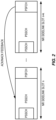
- the new channel called the PSFCH, is mapped to the last symbols available for SL in a slot as represented in Figure 2 .
- FIG. 2 is a schematic diagram of the PSFCH, the Physical SL Shared Channel (PSSCH), and the Physical SL Control Channel (PSCCH) in the time-frequency domain.
- the PSFCH is in the form of a sequence (i.e., sequence-based PSFCH).
- the PSFCH sequence is a low Peak-to-Average Power (PAPR) sequence with good auto-correlation and cross-correlation properties.
- PAPR Peak-to-Average Power
- the ACK or NACK bits being sent are used to determine the corresponding PSFCH sequence.
- PSFCH is a sequence, there is no RS (also known as pilot signal) embedded in the PSFCH, which is in contrast to other physical SL channels like the PSCCH (carrying control information) and the PSSCH (carrying data).
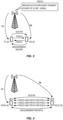
- FIG. 3 is a schematic diagram of SL communications between a Tx UE and an Rx UE using PSSCH for data transmission and PSFCH for HARQ feedback.
- a unidirectional case is illustrated, and in bidirectional cases both UEs act as both a Tx UE and an Rx UE.
- an RS is transmitted by the gNB to each UE.
- the Tx UE transmits a SL Channel State Information RS (SCSI-RS) to the Rx UE.
- SCSI-RS SL Channel State Information RS
- FIG. 4 is a schematic diagram of SL communications between a Tx UE and an Rx UE with multiple parallel SL connections.
- a bidirectional case is illustrated, in which an RS is transmitted by the gNB to each UE (e.g., UE-A and UE-B) and each UE transmits a SCSI-RS to the other UE.
- UE-A and UE-B each UE transmits a SCSI-RS to the other UE.
- PSFCH Physical SL Feedback Channel
- PSSCH Physical SL Shared Channel
- UE User Equipment
- both UEs continuously maintain the estimated SL Path Loss (PL) and transmit a single SL Channel State Information Reference Signal (SCSI-RS), and associated measurement reports rather than triggering new SCSI-RS transmissions and measurement reports for each PSSCH and associated PSFCH channel per SL (e.g., PC5) connection.
- PL SL Path Loss
- SCSI-RS SL Channel State Information Reference Signal
- Radio Node As used herein, a "radio node” is either a radio access node or a wireless communication device.
- Radio Access Node As used herein, a “radio access node” or “radio network node” or “radio access network node” is any node in a Radio Access Network (RAN) of a cellular communications network that operates to wirelessly transmit and/or receive signals.
- RAN Radio Access Network
- a radio access node examples include, but are not limited to, a Base Station (BS) (e.g., a New Radio (NR) BS (gNB) in a Third Generation Partnership Project (3GPP) Fifth Generation (5G) NR network or an enhanced or evolved Node B (eNB) in a 3GPP Long Term Evolution (LTE) network), a high-power or macro BS, a low-power BS (e.g., a micro BS, a pico BS, a home eNB, or the like), a relay node, a network node that implements part of the functionality of a BS (e.g., a network node that implements a gNB Central Unit (gNB-CU) or a network node that implements a gNB Distributed Unit (gNB-DU)) or a network node that implements part of the functionality of some other type of radio access node.
- BS Base Station
- gNB New Radio
- 5G Fifth Generation
- a "core network node” is any type of node in a core network or any node that implements a core network function.
- Some examples of a core network node include, e.g., a Mobility Management Entity (MME), a Packet Data Network Gateway (P-GW), a Service Capability Exposure Function (SCEF), a Home Subscriber Server (HSS), or the like.
- MME Mobility Management Entity
- P-GW Packet Data Network Gateway
- SCEF Service Capability Exposure Function
- HSS Home Subscriber Server
- a core network node examples include a node implementing a Access and Mobility Function (AMF), a User Plane Function (UPF), a Session Management Function (SMF), an Authentication Server Function (AUSF), a Network Slice Selection Function (NSSF), a Network Exposure Function (NEF), a Network Function (NF) Repository Function (NRF), a Policy Control Function (PCF), a Unified Data Management (UDM), or the like.
- AMF Access and Mobility Function
- UPF User Plane Function
- SMF Session Management Function
- AUSF Authentication Server Function
- NSSF Network Slice Selection Function
- NEF Network Exposure Function
- NRF Network Exposure Function
- NRF Network Exposure Function
- PCF Policy Control Function
- UDM Unified Data Management
- a "communication device” is any type of device that has access to an access network.
- Some examples of a communication device include, but are not limited to: mobile phone, smart phone, sensor device, meter, vehicle, household appliance, medical appliance, media player, camera, or any type of consumer electronic, for instance, but not limited to, a television, radio, lighting arrangement, tablet computer, laptop, or Personal Computer (PC).
- the communication device may be a portable, hand-held, computer-comprised, or vehicle-mounted mobile device, enabled to communicate voice and/or data via a wireless or wireline connection.
- Network Node As used herein, a "network node” is any node that is either part of the RAN or the core network of a cellular communications network/system.
- Tx Transmitter
- Receiver (Rx) UE As used herein, a UE that receives the data packet from the Tx UE is referred to as the Rx UE. There is a single Rx UE for a unicast transmission and there are multiple Rx UEs for a groupcast transmission.
- the Rx UE(s) send a Hybrid Automatic Repeat Request (HARQ) acknowledgment (Positive Acknowledgement (ACK) or Negative Acknowledgement (NACK), also known as HARQ feedback) to the Tx UE upon successful or unsuccessful decoding of the packet.
- HARQ acknowledgment for Sidelink (SL) communications is sent in a Physical SL Feedback Channel (PSFCH).
- PSFCH Physical SL Feedback Channel
- Power control for a bidirectional SL is provided. Certain aspects of the present disclosure and their embodiments may provide solutions to the aforementioned or other challenges.
- the solution to Problem 1 described above builds on recognizing that the Rx UE illustrated in Figure 3 under a traditional approach sets the PSFCH power without taking into account the Path Loss (PL) between the Rx UE and Tx UE. This is because under the traditional approach, the PSFCH power is determined based on the estimated PL between the Rx UE and the gNB.
- the proposed solution utilizes the fact that the SL communication is typically bidirectional between the UEs, and the Rx UE acts as a Tx UE in parallel with its Rx role.
- the Rx UE limits the PSFCH transmit power level to that of the power level used for Physical SL Shared Channel (PSSCH) so as to prohibit too high transmit power for the PSFCH.
- the difference between the PSSCH and PSFCH exceeds a preconfigured threshold (e.g., the PSFCH is too low)
- the Rx UE takes preventive actions that ensure sufficient quality over the PSFCH.
- the solution to Problem 2 described above builds on recognizing that a single SL Channel State Information Reference Signal (SCSI-RS) and associated measurements, measurement reports and PL estimation can be reused for the multiple PSSCH and PSFCH channels illustrated in Figure 4 .
- SCSI-RS SL Channel State Information Reference Signal
- the solution elements developed for addressing Problem 1 are combined with both UEs continuously maintaining the estimated SL PL and transmitting a single SCSI-RS and associated measurement reports rather than triggering new SCSI-RS transmissions and measurement reports for each PSSCH and associated PSFCH channel per SL (e.g., PC5) connection.
- Certain embodiments may provide one or more of the following technical advantage(s).
- An advantage of the solution to Problem 1 is that it ensures that the PSFCH does not cause high interference at the BS while setting a sufficiently high PSFCH transmit power for enabling the peer UE to decode the ACK/NACK signaling over the PSFCH with low bit error rate.
- Another advantage of the solution to Problem 2 is that it reduces the need for signaling exchange associated with SCSI-RS and measurement reporting over the SL.
- Figure 5 illustrates one example of a cellular communications system 500 in which embodiments of the present disclosure may be implemented.
- the cellular communications system 500 is a 5G system (5GS) including a NR RAN or LTE RAN (i.e., Evolved Universal Terrestrial RAN (E-UTRAN)) or an Evolved Packet System (EPS) including a LTE RAN.
- 5GS 5G system
- LTE RAN i.e., Evolved Universal Terrestrial RAN (E-UTRAN)
- EPS Evolved Packet System
- the RAN includes BSs 502-1 and 502-2, which in LTE are referred to as eNBs (when connected to an Evolved Packet Core (EPC)) and in 5G NR are referred to as gNBs (e.g., LTE RAN nodes connected to 5G Core (5GC), which are referred to as gn-eNBs), controlling corresponding (macro) cells 504-1 and 504-2.
- the BSs 502-1 and 502-2 are generally referred to herein collectively as BSs 502 and individually as BS 502.
- the (macro) cells 504-1 and 504-2 are generally referred to herein collectively as (macro) cells 504 and individually as (macro) cell 504.
- the RAN may also include a number of low power nodes 506-1 through 506-4 controlling corresponding small cells 508-1 through 508-4.
- the low power nodes 506-1 through 506-4 can be small BSs (such as pico or femto BSs) or Remote Radio Heads (RRHs), or the like.
- RRHs Remote Radio Heads
- one or more of the small cells 508-1 through 508-4 may alternatively be provided by the BSs 502.
- the low power nodes 506-1 through 506-4 are generally referred to herein collectively as low power nodes 506 and individually as low power node 506.
- the small cells 508-1 through 508-4 are generally referred to herein collectively as small cells 508 and individually as small cell 508.
- the cellular communications system 500 also includes a core network 510, which in the 5GS is referred to as the 5GC.
- the BSs 502 (and optionally the low power nodes 506) are connected to the core network 510.
- the BSs 502 and the low power nodes 506 provide service to wireless communication devices 512-1 through 512-5 in the corresponding cells 504 and 508.
- the wireless communication devices 512-1 through 512-5 are generally referred to herein collectively as wireless communication devices 512 and individually as wireless communication device 512. In the following description, the wireless communication devices 512 are oftentimes UEs, but the present disclosure is not limited thereto.
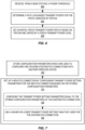
- FIG. 6 is a flowchart illustrating a process for controlling power in bidirectional SL communications.
- the process can address Problem 1 described above. Accordingly, the process is described with reference to Figures 3 and 6 .
- the process includes one or more of the following steps:
- the process may optionally begin at step 600, with receiving, from a BS, a power threshold.
- the gNB sets up (e.g., defines or pre-defines) one or more power thresholds for an individual UE (e.g., each of the Tx UE and the Rx UE).
- Such thresholds specify what level of received interference power is acceptable for the gNB and the maximum difference between the PSSCH and PSFCH transmit power levels.
- the process continues at step 602, with determining (e.g., by the Rx UE) a PL-based transmit power for the PSFCH, denoted by PSFCHO.
- the Rx UE can perform measurements on the Reference Signals (RSs) continuously transmitted by the BS (e.g., gNB) and estimate the PL to the serving BS.
- RSs Reference Signals
- the Rx UE then derives the PL-based PSFCH transmit power PSFCHO such that the caused interference at the BS remains under a predefined threshold (configured by the BS in Step 600): PSFCH 0 ⁇ PL ⁇ Margin ⁇ Predefined Interference Power at BS where Equation 4 constrains the PSFCH transmit power to a PSFCHO value which satisfies the above equation (which may be expressed in decibel-milliwatts (dBm)).
- dBm decibel-milliwatts
- step 604 with setting (e.g., by the Rx UE) an initial PSFCH transmit power PSFCH1 based on PSFCHO and limited by a PSSCH transmit power level.
- the current 3GPP Rel-16 specifications do not support SL PL-based power control for the PSFCH, therefore a solution that is applicable in NR Rel-16 networks must not use SL PL for PSFCH.
- the Rx UE utilizes the fact that it also acts as a Tx UE and thus sets the PSSCH transmit power using existing schemes.
- the initial PSFCH transmit power PSFCH1 is upper bounded by the PSSCH transmit power as well as by the PL-based PSFCH transmit power PSFCHO and thereby it is not unnecessarily high and does not cause high interference at the BS. However, it may be too low with respect to the PSSCH transmit power and the SL distance over which the SL communications take place. Therefore, the Rx UE calculates the absolute value of a difference between the PSSCH transmit power and the initial PSFCH transmit power PSFCH 1: PSSCH transmit power ⁇ PSFCH 1 transmit power and continuously compares this value with a preconfigured threshold TH (from step 600).
- the Rx UE takes the following actions (in any combination):
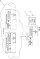
- Figure 7 is a flowchart illustrating another process for controlling power in bidirectional SL communications.
- the process can address Problem 2 described above. Accordingly, the process is described with reference to Figures 4 and 7 .
- This process builds on the key observation that the PSFCH power control and associated parameter configuration can be reused across multiple PC5 connections. Thus, the steps of the process illustrated in Figure 7 can be combined with one or more of the steps of the process illustrated in Figure 6 in order to solve Problem 2.
- the process begins at step 700, with a UE storing configuration parameters which are used to configure one or more existing PC5 connections (e.g., an SL) with another UE (e.g., wireless device).
- the UE can be a Tx UE configuring the PSSCH and/or an Rx UE configuring the PSFCH, and the stored configuration parameters can be ⁇ and P 0 .
- the UE can also store PSSCH and PSFCH transmit power levels for the existing PC5 connection.
- the UE can also store Quality of Service (QoS) parameters (e.g., packet loss rate, maximum bit rate, minimum bit rate, QoS Class Identifier (QCI)) associated with the PC5 connection.
- QoS Quality of Service
- Step 702 with the UE setting up a new PC5 connection by configuring transmit power setting parameters for the new PC5 connection based on the stored configuration parameters.
- Step 702 may optionally include sub-step 704, with the Rx UE configuring the transmit power setting parameters equal to the stored configuration parameters of the existing PC5 connection when setting up a new PC5 connection having QoS parameters similar to those of any of the one or more existing PC5 connections.
- Step 702 may optionally include sub-step 706, with the Tx UE using a higher or lower transmit power setting (e.g., PSSCH transmit power) than that used for the existing PC5 connection when setting up a new PC5 connection with QoS parameters that are different from any of the one or more existing PC5 connections.
- a higher or lower transmit power setting e.g., PSSCH transmit power
- FIG. 8 is a schematic block diagram of a radio access node 800 according to some embodiments of the present disclosure. Optional features are represented by dashed boxes.
- the radio access node 800 may be, for example, a BS 502 or 506 or a network node that implements all or part of the functionality of the BS 502 or gNB described herein.
- the radio access node 800 includes a control system 802 that includes one or more processors 804 (e.g., Central Processing Units (CPUs), Application Specific Integrated Circuits (ASICs), Field Programmable Gate Arrays (FPGAs), and/or the like), memory 806, and a network interface 808.
- the one or more processors 804 are also referred to herein as processing circuitry.
- the radio access node 800 may include one or more radio units 810 that each includes one or more transmitters 812 and one or more receivers 814 coupled to one or more antennas 816.
- the radio units 810 may be referred to or be part of radio interface circuitry.
- the radio unit(s) 810 is external to the control system 802 and connected to the control system 802 via, e.g., a wired connection (e.g., an optical cable).
- the radio unit(s) 810 and potentially the antenna(s) 816 are integrated together with the control system 802.
- the one or more processors 804 operate to provide one or more functions of a radio access node 800 as described herein.
- the function(s) are implemented in software that is stored, e.g., in the memory 806 and executed by the one or more processors 804.
- FIG. 9 is a schematic block diagram that illustrates a virtualized embodiment of the radio access node 800 according to some embodiments of the present disclosure. This discussion is equally applicable to other types of network nodes. Further, other types of network nodes may have similar virtualized architectures. Again, optional features are represented by dashed boxes.
- a "virtualized" radio access node is an implementation of the radio access node 800 in which at least a portion of the functionality of the radio access node 800 is implemented as a virtual component(s) (e.g., via a virtual machine(s) executing on a physical processing node(s) in a network(s)).
- the radio access node 800 may include the control system 802 and/or the one or more radio units 810, as described above.
- the control system 802 may be connected to the radio unit(s) 810 via, for example, an optical cable or the like.
- the radio access node 800 includes one or more processing nodes 900 coupled to or included as part of a network(s) 902.
- Each processing node 900 includes one or more processors 904 (e.g., CPUs, ASICs, FPGAs, and/or the like), memory 906, and a network interface 908.
- processors 904 e.g., CPUs, ASICs, FPGAs, and/or the like
- memory 906 e.g., RAM, ROM, and/or the like
- functions 910 of the radio access node 800 described herein are implemented at the one or more processing nodes 900 or distributed across the one or more processing nodes 900 and the control system 802 and/or the radio unit(s) 810 in any desired manner.
- some or all of the functions 910 of the radio access node 800 described herein are implemented as virtual components executed by one or more virtual machines implemented in a virtual environment(s) hosted by the processing node(s) 900.
- additional signaling or communication between the processing node(s) 900 and the control system 802 is used in order to carry out at least some of the desired functions 910.
- the control system 802 may not be included, in which case the radio unit(s) 810 communicate directly with the processing node(s) 900 via an appropriate network interface(s).
- a computer program including instructions which, when executed by at least one processor, causes the at least one processor to carry out the functionality of radio access node 800 or a node (e.g., a processing node 900) implementing one or more of the functions 910 of the radio access node 800 in a virtual environment according to any of the embodiments described herein is provided.
- a carrier comprising the aforementioned computer program product is provided. The carrier is one of an electronic signal, an optical signal, a radio signal, or a computer readable storage medium (e.g., a non-transitory computer readable medium such as memory).
- FIG 10 is a schematic block diagram of the radio access node 800 according to some other embodiments of the present disclosure.
- the radio access node 800 includes one or more modules 1000, each of which is implemented in software.
- the module(s) 1000 provide the functionality of the radio access node 800 described herein. This discussion is equally applicable to the processing node 900 of Figure 9 where the modules 1000 may be implemented at one of the processing nodes 900 or distributed across multiple processing nodes 900 and/or distributed across the processing node(s) 900 and the control system 802.
- FIG 11 is a schematic block diagram of a wireless communication device 1100 according to some embodiments of the present disclosure.
- the wireless communication device 1100 includes one or more processors 1102 (e.g., CPUs, ASICs, FPGAs, and/or the like), memory 1104, and one or more transceivers 1106 each including one or more transmitters 1108 and one or more receivers 1110 coupled to one or more antennas 1112.
- the transceiver(s) 1106 includes radio-front end circuitry connected to the antenna(s) 1112 that is configured to condition signals communicated between the antenna(s) 1112 and the processor(s) 1102, as will be appreciated by one of ordinary skill in the art.
- the processors 1102 are also referred to herein as processing circuitry.
- the transceivers 1106 are also referred to herein as radio circuitry.
- the functionality of the wireless communication device 1100 described above may be fully or partially implemented in software that is, e.g., stored in the memory 1104 and executed by the processor(s) 1102.
- the wireless communication device 1100 may include additional components not illustrated in Figure 11 such as, e.g., one or more user interface components (e.g., an input/output interface including a display, buttons, a touch screen, a microphone, a speaker(s), and/or the like and/or any other components for allowing input of information into the wireless communication device 1100 and/or allowing output of information from the wireless communication device 1100), a power supply (e.g., a battery and associated power circuitry), etc.
- user interface components e.g., an input/output interface including a display, buttons, a touch screen, a microphone, a speaker(s), and/or the like and/or any other components for allowing input of information into the wireless communication device 1100 and/or allowing output of information from the wireless communication device 1100
- a power supply e.g., a battery and associated power circuitry
- a computer program including instructions which, when executed by at least one processor, causes the at least one processor to carry out the functionality of the wireless communication device 1100 according to any of the embodiments described herein is provided.
- a carrier comprising the aforementioned computer program product is provided.
- the carrier is one of an electronic signal, an optical signal, a radio signal, or a computer readable storage medium (e.g., a non-transitory computer readable medium such as memory).
- FIG 12 is a schematic block diagram of the wireless communication device 1100 according to some other embodiments of the present disclosure.
- the wireless communication device 1100 includes one or more modules 1200, each of which is implemented in software.
- the module(s) 1200 provide the functionality of the wireless communication device 1100 described herein.
- any appropriate steps, methods, features, functions, or benefits disclosed herein may be performed through one or more functional units or modules of one or more virtual apparatuses.
- Each virtual apparatus may comprise a number of these functional units.
- These functional units may be implemented via processing circuitry, which may include one or more microprocessor or microcontrollers, as well as other digital hardware, which may include Digital Signal Processor (DSPs), special-purpose digital logic, and the like.
- the processing circuitry may be configured to execute program code stored in memory, which may include one or several types of memory such as Read Only Memory (ROM), Random Access Memory (RAM), cache memory, flash memory devices, optical storage devices, etc.
- Program code stored in memory includes program instructions for executing one or more telecommunications and/or data communications protocols as well as instructions for carrying out one or more of the techniques described herein.
- the processing circuitry may be used to cause the respective functional unit to perform corresponding functions according one or more embodiments of the present disclosure.
Landscapes
- Engineering & Computer Science (AREA)
- Computer Networks & Wireless Communication (AREA)
- Signal Processing (AREA)
- Quality & Reliability (AREA)
- Mobile Radio Communication Systems (AREA)
Claims (9)
- Procédé réalisé par un dispositif de communication sans fil (512) pour commander une puissance dans des communications de liaison latérale, SL, bidirectionnelles, le procédé comprenant :- la détermination (602) d'une puissance de transmission basée sur l'affaiblissement de propagation, PL, pour un canal de rétroaction SL physique, PSFCH, sur la base d'une PL estimée à une station de base, BS (502) ; et- la définition (604) d'une puissance de transmission PSFCH initiale comme le plus petit parmi la puissance de transmission basée sur PL pour le PSFCH et un niveau de puissance de transmission de canal partagé de SL physique, PSSCH.
- Procédé selon la revendication 1, comprenant en outre la réception d'un seuil préconfiguré reçu depuis une station de base, BS, (502), dans lequel le seuil préconfiguré spécifie un niveau d'interférence acceptable au niveau de la BS et une différence maximale entre des niveaux de puissance de transmission PSSCH et PSFCH, le procédé comprenant en outre :le calcul d'une valeur absolue d'une différence entre le niveau de puissance de transmission PSSCH et la puissance de transmission PSFCH initiale ; etla comparaison de la valeur absolue au seuil préconfiguré.
- Procédé selon la revendication 2, comprenant en outre la réalisation d'une mesure sur un signal de référence, RS, transmis par la BS (502) ;
dans lequel la puissance de transmission basée sur PL pour le PSFCH est déduite de la mesure sur le RS de sorte qu'une interférence au niveau de la BS reste inférieure au seuil préconfiguré. - Procédé selon l'une quelconque des revendications 1 à 3, dans lequel le dispositif de communication sans fil (512) est un équipement utilisateur, UE, récepteur, Rx.
- Procédé selon l'une quelconque des revendications 1 à 4, dans lequel le dispositif de communication sans fil (512) est un équipement utilisateur, UE, émetteur, Tx.
- Procédé selon la revendication 2, comprenant en outre, si la valeur absolue dépasse le seuil préconfiguré, la notification d'au moins l'un parmi une station de base, BS, (502) et un autre dispositif de communication sans fil (512) participant aux communications SL, que la puissance de transmission PSFCH initiale est trop basse.
- Procédé selon l'une quelconque des revendications 2 et 6, comprenant en outre, si la valeur absolue dépasse le seuil préconfiguré, la demande d'un ou plusieurs nouveaux paramètres de configuration à une station de base, BS, (502) de sorte que la puissance de transmission PSFCH puisse être augmentée.
- Procédé selon l'une quelconque des revendications 2, 6 et 7, comprenant en outre, si la valeur absolue dépasse le seuil préconfiguré, la commutation à une communication cellulaire au lieu des communications SL.
- Dispositif de communication sans fil (512) pour commander une puissance dans des communications de liaison latérale, SL, bidirectionnelles, le dispositif de communication sans fil comprenant :- une interface de communication (1106) ; et- une circuiterie de traitement (1102) configurée pour réaliser l'une quelconque des étapes selon l'une quelconque des revendications 1 à 8.
Applications Claiming Priority (2)
| Application Number | Priority Date | Filing Date | Title |
|---|---|---|---|
| US201962933013P | 2019-11-08 | 2019-11-08 | |
| PCT/IB2020/060535 WO2021090295A1 (fr) | 2019-11-08 | 2020-11-09 | Commande de puissance liaison latérale bidirectionnelle |
Publications (3)
| Publication Number | Publication Date |
|---|---|
| EP4055908A1 EP4055908A1 (fr) | 2022-09-14 |
| EP4055908B1 true EP4055908B1 (fr) | 2025-03-26 |
| EP4055908C0 EP4055908C0 (fr) | 2025-03-26 |
Family
ID=73455760
Family Applications (1)
| Application Number | Title | Priority Date | Filing Date |
|---|---|---|---|
| EP20808199.2A Active EP4055908B1 (fr) | 2019-11-08 | 2020-11-09 | Commande de puissance pour une liaison latérale bidirectionnelle |
Country Status (3)
| Country | Link |
|---|---|
| US (1) | US12219495B2 (fr) |
| EP (1) | EP4055908B1 (fr) |
| WO (1) | WO2021090295A1 (fr) |
Families Citing this family (1)
| Publication number | Priority date | Publication date | Assignee | Title |
|---|---|---|---|---|
| US12439347B2 (en) | 2021-10-27 | 2025-10-07 | Electronics And Telecommunications Research Institute | Sidelink communication method and apparatus |
Family Cites Families (3)
| Publication number | Priority date | Publication date | Assignee | Title |
|---|---|---|---|---|
| US11496246B2 (en) * | 2019-01-10 | 2022-11-08 | Samsung Electronics Co., Ltd. | HARQ operation and power control in sidelink |
| CN113785628B (zh) * | 2019-04-09 | 2023-12-19 | Lg电子株式会社 | 确定nr v2x中的副链路发送功率的方法以及同步 |
| ES2939262T3 (es) * | 2019-07-19 | 2023-04-20 | Asustek Comp Inc | Procedimiento y aparato para derivar la pérdida de trayectoria de enlace descendente para el control de potencia de transmisión de dispositivo a dispositivo en un sistema de comunicación inalámbrica |
-
2020
- 2020-11-09 EP EP20808199.2A patent/EP4055908B1/fr active Active
- 2020-11-09 US US17/774,644 patent/US12219495B2/en active Active
- 2020-11-09 WO PCT/IB2020/060535 patent/WO2021090295A1/fr not_active Ceased
Also Published As
| Publication number | Publication date |
|---|---|
| EP4055908A1 (fr) | 2022-09-14 |
| US12219495B2 (en) | 2025-02-04 |
| US20220377674A1 (en) | 2022-11-24 |
| EP4055908C0 (fr) | 2025-03-26 |
| WO2021090295A1 (fr) | 2021-05-14 |
Similar Documents
| Publication | Publication Date | Title |
|---|---|---|
| US12557031B2 (en) | Power control for uplink transmissions towards multiple TRPs | |
| US11553436B2 (en) | Airborne status dependent uplink power control related task(s) for aerial UEs | |
| US10932200B2 (en) | Uplink power control method and apparatus to reduce user equipment-to-user equipment cross interference | |
| CN105934893B (zh) | 一种传输信号的方法和设备 | |
| EP2995156B1 (fr) | Gestion améliorée de l'émission de communications de réseau et de la réception simultanée de communications d2d ou de la réception de communications de réseau et de l'émission simultanée de communications d2d | |
| US9814002B2 (en) | Apparatus and method for controlling transmission power in wireless communication system | |
| EP3070983B1 (fr) | Procédé et disposition pour la gestion d'une commande de puissance | |
| US9185733B2 (en) | Method of device-to-device communication in wireless mobile communication system | |
| US11082975B2 (en) | Uplink transmit power control information determination for performing uplink sending | |
| CN105722200B (zh) | 无线通信系统中的电子设备和无线通信方法 | |
| US11178698B2 (en) | Power control of random access in NB-IoT | |
| JP7509438B2 (ja) | 方法、及び端末 | |
| US20240188001A1 (en) | Ul power control for transport block transmission over multiple slots | |
| JP5089754B2 (ja) | 移動通信システム、基地局及び送信電力制御方法 | |
| EP4055908B1 (fr) | Commande de puissance pour une liaison latérale bidirectionnelle | |
| WO2025229385A1 (fr) | Systèmes et procédés de commutation entre un saut de fréquence et un saut de non-fréquence | |
| OA20221A (en) | Airborne status dependent uplink power control related task(S) for aerial UEs. |
Legal Events
| Date | Code | Title | Description |
|---|---|---|---|
| STAA | Information on the status of an ep patent application or granted ep patent |
Free format text: STATUS: UNKNOWN |
|
| STAA | Information on the status of an ep patent application or granted ep patent |
Free format text: STATUS: THE INTERNATIONAL PUBLICATION HAS BEEN MADE |
|
| PUAI | Public reference made under article 153(3) epc to a published international application that has entered the european phase |
Free format text: ORIGINAL CODE: 0009012 |
|
| STAA | Information on the status of an ep patent application or granted ep patent |
Free format text: STATUS: REQUEST FOR EXAMINATION WAS MADE |
|
| 17P | Request for examination filed |
Effective date: 20220429 |
|
| AK | Designated contracting states |
Kind code of ref document: A1 Designated state(s): AL AT BE BG CH CY CZ DE DK EE ES FI FR GB GR HR HU IE IS IT LI LT LU LV MC MK MT NL NO PL PT RO RS SE SI SK SM TR |
|
| DAV | Request for validation of the european patent (deleted) | ||
| DAX | Request for extension of the european patent (deleted) | ||
| STAA | Information on the status of an ep patent application or granted ep patent |
Free format text: STATUS: EXAMINATION IS IN PROGRESS |
|
| 17Q | First examination report despatched |
Effective date: 20240404 |
|
| GRAP | Despatch of communication of intention to grant a patent |
Free format text: ORIGINAL CODE: EPIDOSNIGR1 |
|
| STAA | Information on the status of an ep patent application or granted ep patent |
Free format text: STATUS: GRANT OF PATENT IS INTENDED |
|
| INTG | Intention to grant announced |
Effective date: 20241029 |
|
| GRAS | Grant fee paid |
Free format text: ORIGINAL CODE: EPIDOSNIGR3 |
|
| GRAA | (expected) grant |
Free format text: ORIGINAL CODE: 0009210 |
|
| STAA | Information on the status of an ep patent application or granted ep patent |
Free format text: STATUS: THE PATENT HAS BEEN GRANTED |
|
| AK | Designated contracting states |
Kind code of ref document: B1 Designated state(s): AL AT BE BG CH CY CZ DE DK EE ES FI FR GB GR HR HU IE IS IT LI LT LU LV MC MK MT NL NO PL PT RO RS SE SI SK SM TR |
|
| REG | Reference to a national code |
Ref country code: GB Ref legal event code: FG4D |
|
| REG | Reference to a national code |
Ref country code: CH Ref legal event code: EP |
|
| REG | Reference to a national code |
Ref country code: DE Ref legal event code: R096 Ref document number: 602020048413 Country of ref document: DE |
|
| REG | Reference to a national code |
Ref country code: IE Ref legal event code: FG4D |
|
| U01 | Request for unitary effect filed |
Effective date: 20250415 |
|
| U07 | Unitary effect registered |
Designated state(s): AT BE BG DE DK EE FI FR IT LT LU LV MT NL PT RO SE SI Effective date: 20250422 |
|
| PG25 | Lapsed in a contracting state [announced via postgrant information from national office to epo] |
Ref country code: RS Free format text: LAPSE BECAUSE OF FAILURE TO SUBMIT A TRANSLATION OF THE DESCRIPTION OR TO PAY THE FEE WITHIN THE PRESCRIBED TIME-LIMIT Effective date: 20250626 |
|
| PG25 | Lapsed in a contracting state [announced via postgrant information from national office to epo] |
Ref country code: NO Free format text: LAPSE BECAUSE OF FAILURE TO SUBMIT A TRANSLATION OF THE DESCRIPTION OR TO PAY THE FEE WITHIN THE PRESCRIBED TIME-LIMIT Effective date: 20250626 |
|
| PG25 | Lapsed in a contracting state [announced via postgrant information from national office to epo] |
Ref country code: HR Free format text: LAPSE BECAUSE OF FAILURE TO SUBMIT A TRANSLATION OF THE DESCRIPTION OR TO PAY THE FEE WITHIN THE PRESCRIBED TIME-LIMIT Effective date: 20250326 |
|
| PG25 | Lapsed in a contracting state [announced via postgrant information from national office to epo] |
Ref country code: GR Free format text: LAPSE BECAUSE OF FAILURE TO SUBMIT A TRANSLATION OF THE DESCRIPTION OR TO PAY THE FEE WITHIN THE PRESCRIBED TIME-LIMIT Effective date: 20250627 |
|
| PG25 | Lapsed in a contracting state [announced via postgrant information from national office to epo] |
Ref country code: SM Free format text: LAPSE BECAUSE OF FAILURE TO SUBMIT A TRANSLATION OF THE DESCRIPTION OR TO PAY THE FEE WITHIN THE PRESCRIBED TIME-LIMIT Effective date: 20250326 |
|
| PG25 | Lapsed in a contracting state [announced via postgrant information from national office to epo] |
Ref country code: ES Free format text: LAPSE BECAUSE OF FAILURE TO SUBMIT A TRANSLATION OF THE DESCRIPTION OR TO PAY THE FEE WITHIN THE PRESCRIBED TIME-LIMIT Effective date: 20250326 |
|
| PG25 | Lapsed in a contracting state [announced via postgrant information from national office to epo] |
Ref country code: PL Free format text: LAPSE BECAUSE OF FAILURE TO SUBMIT A TRANSLATION OF THE DESCRIPTION OR TO PAY THE FEE WITHIN THE PRESCRIBED TIME-LIMIT Effective date: 20250326 |
|
| PG25 | Lapsed in a contracting state [announced via postgrant information from national office to epo] |
Ref country code: SK Free format text: LAPSE BECAUSE OF FAILURE TO SUBMIT A TRANSLATION OF THE DESCRIPTION OR TO PAY THE FEE WITHIN THE PRESCRIBED TIME-LIMIT Effective date: 20250326 |
|
| PG25 | Lapsed in a contracting state [announced via postgrant information from national office to epo] |
Ref country code: IS Free format text: LAPSE BECAUSE OF FAILURE TO SUBMIT A TRANSLATION OF THE DESCRIPTION OR TO PAY THE FEE WITHIN THE PRESCRIBED TIME-LIMIT Effective date: 20250726 |
|
| U20 | Renewal fee for the european patent with unitary effect paid |
Year of fee payment: 6 Effective date: 20251126 |
|
| PG25 | Lapsed in a contracting state [announced via postgrant information from national office to epo] |
Ref country code: CZ Free format text: LAPSE BECAUSE OF FAILURE TO SUBMIT A TRANSLATION OF THE DESCRIPTION OR TO PAY THE FEE WITHIN THE PRESCRIBED TIME-LIMIT Effective date: 20250326 |
|
| PLBE | No opposition filed within time limit |
Free format text: ORIGINAL CODE: 0009261 |
|
| STAA | Information on the status of an ep patent application or granted ep patent |
Free format text: STATUS: NO OPPOSITION FILED WITHIN TIME LIMIT |
|
| REG | Reference to a national code |
Ref country code: CH Ref legal event code: L10 Free format text: ST27 STATUS EVENT CODE: U-0-0-L10-L00 (AS PROVIDED BY THE NATIONAL OFFICE) Effective date: 20260211 |
|
| 26N | No opposition filed |
Effective date: 20260105 |