EP4055941B1 - Dispositifs de communication, équipement d'infrastructure, et procédés - Google Patents
Dispositifs de communication, équipement d'infrastructure, et procédés Download PDFInfo
- Publication number
- EP4055941B1 EP4055941B1 EP20800215.4A EP20800215A EP4055941B1 EP 4055941 B1 EP4055941 B1 EP 4055941B1 EP 20800215 A EP20800215 A EP 20800215A EP 4055941 B1 EP4055941 B1 EP 4055941B1
- Authority
- EP
- European Patent Office
- Prior art keywords
- communications
- uplink
- regions
- resources
- communications resources
- Prior art date
- Legal status (The legal status is an assumption and is not a legal conclusion. Google has not performed a legal analysis and makes no representation as to the accuracy of the status listed.)
- Active
Links
Images








Classifications
-
- H—ELECTRICITY
- H04—ELECTRIC COMMUNICATION TECHNIQUE
- H04W—WIRELESS COMMUNICATION NETWORKS
- H04W72/00—Local resource management
- H04W72/04—Wireless resource allocation
-
- H—ELECTRICITY
- H04—ELECTRIC COMMUNICATION TECHNIQUE
- H04L—TRANSMISSION OF DIGITAL INFORMATION, e.g. TELEGRAPHIC COMMUNICATION
- H04L5/00—Arrangements affording multiple use of the transmission path
- H04L5/003—Arrangements for allocating sub-channels of the transmission path
- H04L5/0053—Allocation of signalling, i.e. of overhead other than pilot signals
-
- H—ELECTRICITY
- H04—ELECTRIC COMMUNICATION TECHNIQUE
- H04W—WIRELESS COMMUNICATION NETWORKS
- H04W72/00—Local resource management
- H04W72/20—Control channels or signalling for resource management
- H04W72/21—Control channels or signalling for resource management in the uplink direction of a wireless link, i.e. towards the network
-
- H—ELECTRICITY
- H04—ELECTRIC COMMUNICATION TECHNIQUE
- H04W—WIRELESS COMMUNICATION NETWORKS
- H04W72/00—Local resource management
- H04W72/50—Allocation or scheduling criteria for wireless resources
- H04W72/54—Allocation or scheduling criteria for wireless resources based on quality criteria
- H04W72/541—Allocation or scheduling criteria for wireless resources based on quality criteria using the level of interference
Definitions
- the present disclosure relates to communications devices which are configured to transmit data to infrastructure equipment in a wireless communications network, where the transmission of the data by the communications devices may be pre-empted by another transmission.
- LTE Long Term Evolution
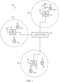
- Figure 1 provides a schematic diagram illustrating some basic functionality of a mobile telecommunications network / system 10 operating generally in accordance with LTE principles, but which may also support other radio access technologies, and which may be adapted to implement embodiments of the disclosure as described herein.
- Various elements of Figure 1 and certain aspects of their respective modes of operation are well-known and defined in the relevant standards administered by the 3GPP (RTM) body, and also described in many books on the subject, for example, Holma H. and Toskala A [2].
- the network 10 includes a plurality of base stations 11 connected to a core network 12. Each base station provides a coverage area 13 (i.e. a cell) within which data can be communicated to and from terminal devices 14. Data is transmitted from base stations 11 to terminal devices 14 within their respective coverage areas 13 via a radio downlink (DL). Data is transmitted from terminal devices 14 to the base stations 11 via a radio uplink (UL).
- the core network 12 routes data to and from the terminal devices 14 via the respective base stations 11 and provides functions such as authentication, mobility management, charging and so on. Terminal devices may also be referred to as mobile stations, user equipment (UE), user terminal, mobile radio, communications device, and so forth.
- Base stations which are an example of network infrastructure equipment / network access node, may also be referred to as transceiver stations / nodeBs / e-nodeBs / eNBs / g-nodeBs / gNBs and so forth.
- transceiver stations / nodeBs / e-nodeBs / eNBs / g-nodeBs / gNBs and so forth.
- the embodiments of the present invention can find application with advanced wireless communications systems such as those referred to as 5G or New Radio (NR) Access Technology.
- advanced wireless communications systems such as those referred to as 5G or New Radio (NR) Access Technology.
- NR New Radio
- the use cases that are considered for NR include:
- URLLC services require that a URLLC data packet (e.g. 32 bytes) is required to be transmitted from the radio protocol layer 2/3 Service Data Unit (SDU) ingress point to the radio protocol layer 2/3 SDU egress point of the radio interface with a latency that is less than 1 ms or 0.5 ms and with a reliability of 99.999% to 99.9999%.
- eURLLC services require high reliability and low latency, and may find applications in factory automation, the transport industry, electrical power distribution and the like.
- eMBB services are characterised by high capacity with a requirement to support high data rates (e.g. up to 20 Gb/s) with moderate latencies and reliabilities (e.g. 99% to 99.9%).
- the elements of the wireless access network shown in Figure 1 may be equally applied to a 5G new RAT configuration, except that a change in terminology may be applied as mentioned above.
- FIG. 2 is a schematic diagram illustrating a network architecture for a new RAT wireless mobile telecommunications network / system 30 based on previously proposed approaches which may also be adapted to provide functionality in accordance with embodiments of the disclosure described herein.
- the new RAT network 30 represented in Figure 2 comprises a first communication cell 20 and a second communication cell 21.
- Each communication cell 20, 21, comprises a controlling node (centralised unit, CU) 26, 28 in communication with a core network component 31 over a respective wired or wireless link 36, 38.
- the respective controlling nodes 26, 28 are also each in communication with a plurality of distributed units (radio access nodes / remote transmission and reception points (TRPs)) 22, 24 in their respective cells. Again, these communications may be over respective wired or wireless links.
- TRPs remote transmission and reception points
- the core network component 31 of the new RAT telecommunications system represented in Figure 2 may be broadly considered to correspond with the core network 12 represented in Figure 1 , and the respective controlling nodes 26, 28 and their associated distributed units / TRPs 22, 24 may be broadly considered to provide functionality corresponding to base stations of Figure 1 , and so these terms (as well as indeed eNodeB, eNB, gNodeB, gNB, etc.) are interchangeable.
- the term network infrastructure equipment / access node may be used to encompass these elements and more conventional base station type elements of wireless telecommunications systems.
- the responsibility for scheduling transmissions which are scheduled on the radio interface between the respective distributed units and the terminal devices may lie with the controlling node / centralised unit and / or the distributed units / TRPs.
- a terminal device 40 is represented in Figure 2 within the coverage area of the first communication cell 20. This terminal device 40 may thus exchange signalling with the first controlling node 26 in the first communication cell via one of the distributed units 22 associated with the first communication cell 20. In some cases communications for a given terminal device are routed through only one of the distributed units, but it will be appreciated in some other implementations communications associated with a given terminal device may be routed through more than one distributed unit, for example in a soft handover scenario and other scenarios.
- the particular distributed unit(s) through which a terminal device is currently connected through to the associated controlling node may be referred to as active distributed units for the terminal device.
- the active subset of distributed units for a terminal device may comprise one or more than one distributed unit (DU/TRP).
- the controlling node 26 is responsible for determining which of the distributed units 22 spanning the first communication cell 20 is responsible for radio communications with the terminal device 40 at any given time (i.e. which of the distributed units are currently active distributed units for the terminal device). Typically this will be based on measurements of radio channel conditions between the terminal device 40 and respective ones of the distributed units 22.
- the subset of the distributed units in a cell which are currently active for a terminal device will depend, at least in part, on the location of the terminal device within the cell (since this contributes significantly to the radio channel conditions that exist between the terminal device and respective ones of the distributed units).
- the involvement of the distributed units in routing communications from the terminal device to a controlling node is transparent to the terminal device 40. That is to say, in some cases the terminal device may not be aware of which distributed unit is responsible for routing communications between the terminal device 40 and the controlling node 26 of the communication cell 20 in which the terminal device is currently operating, or even if any distributed units 22 are connected to the controlling node 26 and involved in the routing of communications at all. In such cases, as far as the terminal device is concerned, it simply transmits uplink data to the controlling node 26 and receives downlink data from the controlling node 26 and the terminal device has no awareness of the involvement of the distributed units 22, though may be aware of radio configurations transmitted by distributed units 22.
- a terminal device may be aware of which distributed unit(s) are involved in its communications. Switching and scheduling of the one or more distributed units may be done at the network controlling node based on measurements by the distributed units of the terminal device uplink signal or measurements taken by the terminal device and reported to the controlling node via one or more distributed units.
- two communication cells 20, 21 and one terminal device 40 are shown for simplicity, but it will of course be appreciated that in practice the system may comprise a larger number of communication cells (each supported by a respective controlling node and plurality of distributed units) serving a larger number of terminal devices.
- Figure 2 represents merely one example of a proposed architecture for a new RAT telecommunications system in which approaches in accordance with the principles described herein may be adopted, and the functionality disclosed herein may also be applied in respect of wireless telecommunications systems having different architectures.
- the network infrastructure equipment / access node may comprise a base station, such as an LTE-type base station 11 as shown in Figure 1 which is adapted to provide functionality in accordance with the principles described herein, and in other examples the network infrastructure equipment may comprise a control unit / controlling node 26, 28 and / or a TRP 22, 24 of the kind shown in Figure 2 which is adapted to provide functionality in accordance with the principles described herein.
- a base station such as an LTE-type base station 11 as shown in Figure 1 which is adapted to provide functionality in accordance with the principles described herein
- the network infrastructure equipment may comprise a control unit / controlling node 26, 28 and / or a TRP 22, 24 of the kind shown in Figure 2 which is adapted to provide functionality in accordance with the principles described herein.
- transmissions may be separated in time and frequency. That is, a transmission may use a set of resources defined in terms of a time period and a frequency range, and different transmissions may use other, non-overlapping resources and may accordingly be received and decoded individually.
- resources is used to refer to (jointly) time and frequency resources.
- a resource may refer to any portion of a range of parameters that may apply to a transmission, such that the use of the same resource for the transmission of two different pieces of information (for example, an eMBB transmission and a ULLRC transmission) is either not feasible or likely to result in severe decrease in the likelihood of successful reception of one or both.
- Other examples of resources may therefore include orthogonal spreading codes, orthogonal spatial transmission links, and the like.
- a resource may be defined in terms of a combination of multiple such parameters (as in the examples described herein, wherein a resource is characterised by time and frequency), or may refer to a single dimension (e.g. by reference solely to time).
- a mobile communications network such as the network illustrated in Figure 2 may be used to carry transmissions for services with a variety of constraints, such as high data rate traffic which has some tolerance to delay and traffic which has a low tolerance to delay, which may also have a lower data rate.
- a network element e.g. TRP, eNB, BTS,
- eMBB and URLLC data to a terminal device
- 3G networks LTE networks (such as that illustrated in Figure 1 ) or any other suitable network and to any appropriate type or types of data.
- the same principles and teachings can also be used for uplink transmissions from a terminal device to a network receiver (e.g. BTS, eNB, TRP, etc.) or for transmissions between peer devices.
- the disclosure is not so limited.
- the disclosure is pertinent where the transmission data transmitted to a different device (the URLLC in embodiments) has different latency & reliability requirement to the transmission data for which the resources are initially allocated (the eMBB in embodiments) and the data transmitted to the different device uses some or all of the resources initially allocated.
- a principle of eMBB data is that, in order to reduce the overhead associated with control information, the data transmission occurs over a relatively long time period (e.g. 0.5ms, 1ms, 5ms, 10ms or 50ms), and as such the control channel associated with an eMBB transmission uses significantly smaller transmission resources than that of the data channel. In this manner, the relative overhead caused by the transmission of control information is reduced.
- the URLLC data resources may be relatively shorter, such as 0.25ms.
- An example requirement currently considered for URLLC is a low latency transmission measured from the ingress of a layer 2 packet to its egress from the network, with a proposed target of 1 ms.
- URLLC Since URLLC is intolerant to latency, it is agreed that URLLC can occupy (that is, be transmitted using) a subset of the resources that have been previously allocated for an eMBB transmission.
- a URLLC transmission may comprise a relatively smaller amount of data than an eMBB transmission, it may be necessary that, for example in order to meet a latency requirement, a URLLC transmission occupies a very high bandwidth for a short time period.
- the bandwidth (i.e. the extent of the transmission resources when measured in the frequency domain) used for a URLLC transmission may therefore exceed that of an eMBB transmission.
- the bandwidth used for a single URLLC transmission may span the frequency range used by two or more ongoing eMBB transmissions. As such, a particular problem arises when a single URLLC transmission uses resources allocated for two or more different eMBB transmissions. This is illustrated in Figure 3 .
- Figure 3 illustrates data transmissions from a base station or gNB to terminal devices. On the horizontal axis is shown a progression of time while the vertical axis shows a frequency range.
- the data transmissions 50, 52 having a relatively longer time duration that are transmitted to UE1 and UE3 are examples of first and second eMBB transmissions, while the transmission 54 using a relatively larger frequency range over a shorter time period that is transmitted to UE2 is an example of a URLLC transmission.
- the URLLC transmission 54 uses resources which have been allocated for the first and second eMBB transmissions 50, 52.
- Figure 3 also illustrates the principle that an eMBB transmission typically occurs over a long duration but over a relatively limited frequency range while a URLLC transmission may occupy a much shorter time period but may use a much wider range of frequencies in order to meet the latency requirement of the URLLC data.
- URLLC transmission for example URLLC transmission 54
- eMBB data for example eMBB transmissions 50, 52
- eMBB transmissions 50, 52 the resource previously allocated for another, lower priority, transmission
- eMBB data for example eMBB transmissions 50, 52
- the possibility of correctly decoding the affected eMBB transmissions 50, 52 will be negatively impacted by the fact that some portion of the resources which were allocated for their transmission has in fact been used for the transmission of the URLLC data 54.
- FIG. 3 An example of a DL PI 56 is also shown in Figure 3 , where as described above eMBB transmission 50 is transmitted to a UE, e.g. UE1, between time ⁇ 1 and ⁇ 5 .
- the gNB transmits URLLC transmission 54 to another UE, e.g. UE2, where this URLLC transmission 54 ends at time ⁇ 4 .
- the URLLC transmission 54 for UE2 pre-empts part of the resources that are originally scheduled for UE1's eMBB transmission 50.
- a downlink Pre-emption Indicator (DL PI) 56 is transmitted by the gNB at time ⁇ 7 to indicate to UE1 that part of its resources have been pre-empted so that UE1 can take ameliorative steps in decoding the eMBB message 50; for example, UE1 can zero out the soft bits corresponding to the pre-empted parts.
- DL PI Downlink Pre-emption Indicator
- the DL Pre-emption Indicator is transmitted using Downlink Control Information (DCI); specifically, a Group Common DCI (GC-DCI, also known as DCI Format 2_1 in 3GPP [6]), where a GC-DCI contains control information for a group of UEs.
- DCI Downlink Control Information
- GC-DCI Group Common DCI
- a GC-DCI contains control information for a group of UEs.
- the rationale behind using a GC-DCI is that the URLLC in the downlink is expected to occupy a wide frequency bandwidth (but a narrow period of time) and so it is likely that the URLLC will pre-empt more than one eMBB UE.
- URLLC transmission 54 transmitted to UE2 occupies frequency resource from f 2 to f 5 , which would pre-empt resources 50, 52 originally scheduled for UE1 and UE3.
- This Pre-emption Indicator 56 just needs to indicate the resources occupied by the URLLC transmission 54, e.g. occupying time ⁇ 3 to ⁇ 4 and frequency f 2 to f 5 .
- the UEs receiving this Pre-emption Indicator 56 will determine which resources 54 indicated by the Pre-emption Indicator 56 overlap with their most recent eMBB transmission 50, 52; for example in Figure 3 , UE1 will determine that the resources between time ⁇ 3 and ⁇ 4 and frequency f 2 and f 3 are pre-empted, whilst UE3 will determine that the resources between time ⁇ 3 and ⁇ 4 and frequency f 4 and f 5 are pre-empted.
- the GC-DCI carrying the Downlink Pre-emption Indicator addresses a Reference Downlink Region (RDR).
- RDR Reference Downlink Region
- the Pre-emption Indicator 56 carried by the GC-DCI only indicates pre-empted resources if those pre-empted resources fall within this RDR 58 and an eMBB UE with a transmission 50, 52 that falls within the RDR 58 will read the Pre-emption Indicator 56 in the corresponding GC-DCI to determine where (if any), the pre-empted resources are.
- the RDR occurs periodically in time, i.e. a GC-DCI is monitored periodically, and occupies a fixed frequency region.
- the frequency region occupied by the RDR is equivalent to the Bandwidth Part (BWP) of the UEs configured to monitor the GC-DCI corresponding to that RDR.
- BWP Bandwidth Part
- the BWP is a fraction of the system bandwidth configured by the network for a UE to operate in and the rationale for the use of BWPs is that a UE operating in a narrow bandwidth would consume less power than one operating over the whole (and much wider) system bandwidth.
- the number of information bits for the Downlink Pre-emption Indicator is fixed at 14 bits, where it can be RRC configured to indicate either a bitmap of 1 ⁇ 14 or a bitmap of 2 ⁇ 7, which determines how the RDR is divided into resource regions. That is, the RDR can be divided into 1 frequency region by 14 time regions or 2 frequency regions by 7 time regions. This is shown in Figures 4A and 4B , where an RDR is shown to occupy time ⁇ 0 to ⁇ 14 and frequency f 0 to f 2 .
- the RDR resource regions grid in Figure 4A is represented by the bitmap of dimension 1 ⁇ 14 and the RDR resource regions grid in Figure 4B is represented by the configured bitmap of dimension 2 ⁇ 7.
- the bitmap will indicate which resource region(s) is pre-empted.
- the Downlink Pre-emption Indicator indicates which of these regions are pre-empted by another (URLLC) UE.
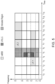
- Two eMBB UEs, UE1 and UE3 are scheduled at time ⁇ 2 and ⁇ 4 respectively and during the transmissions of these two eMBB UEs, the gNB transmits a URLLC transmission to UE2 during time ⁇ 4 to ⁇ 5 , which pre-empted some of the resources for UE1. If the resource grid using bitmap 2 ⁇ 7 is configured, the gNB would indicate that two resource regions, i.e. the entire RDR between times ⁇ 4 and ⁇ 6 , is pre-empted as shown in green blocks in Figure 5 .
- UE1 would then assume a much larger pre-empted region than necessary, and UE3 - which is not even pre-empted - would assume that a quarter of its resources are pre-empted.
- the coarse granularity of the Pre-emption Indicator causes ghost pre-emption; i.e. resources that are not pre-empted but are wrongly indicated to be pre-empted. This can have significant impact on the UE's decoding performance.
- UL CI Uplink Cancellation Indicator
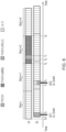
- UE1 with eMBB traffic receives an UL grant at time t 1 for a PUSCH transmission starting at time t 5 occupying the entire slot n +2 .
- UE2 with UL URLLC traffic receives an UL grant for a PUSCH transmission at time t 6 occupying 2 symbols, where this transmission uses some of the resources originally scheduled for UE1.
- the gNB transmits an UL CI to UE1 at time t 3 , indicating that its transmission has been pre-empted and that it should stop its PUSCH transmission so that it does not introduce any interference to UE2. It should be noted that unlike the downlink where the DL PI is transmitted after the pre-emption occurs, in the uplink the UL CI is transmitted before the pre-emption occurs so that the victim eMBB UE, e.g. UE1, is able to stop its PUSCH transmission.
- an UL CI is configured using 14 bits to represent a time-frequency portion with dimensions 2 ⁇ 7.
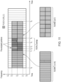
- the RUR has a time duration of 14 symbols and ranges from frequency f 1 to f 3 .
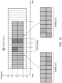
- the periodicity of the UL CI is such that two successive RURs overlap by 6 symbols, as shown in Figure 12 , where RUR#1 spans time t 0 to t 4 and RUR#2 spans time t 1 to t 5 overlaps between time t 1 and t 4 .
- RUR#1 indicates that the portions between time t 1 and t 3 and frequency f 1 to f 2 are pre-empted.
- a second such condition of the RUR is that there is collision between the RUR and DL symbols in a TDD system.
- TDD systems there have been previously made proposals to exclude DL symbols from the RUR. This means that the "active" RUR region would be reduced, resulting in a finer time-frequency portion granularity.
- the DL symbols can be:
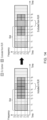
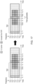
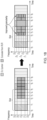
- the communications device 101 may further be configured to determine that an overlapping portion of one of the reference regions overlaps in both of frequency and time with a region of the wireless access interface that is dedicated for downlink transmissions, the one of the reference regions being formed of a specified number of sub-regions, to determine that one or more of the sub-regions that are at least partially located within the overlapping portion of the one of the reference regions are to be excluded from the one of the reference regions, and to repartition at least some of the sub-regions that are not to be excluded from the one of the reference regions to form smaller sub-regions such that, after the adjustment, the number of sub-regions that are not to be excluded from the one of the reference regions is equal to the specified number of sub-regions.
- the one of the reference regions for which sub-regions are either excluded or repartitioned/divided may be either of the first or second reference regions as described with respect to Figure 10 , or may be a different reference region that is not either of the first or second reference regions.
- repartitioning as used herein may refer to dividing a sub-region in half or by some other amount in at least one of time or frequency. Alternatively, it would be understood that repartitioning may refer to, for example, increasing the size of a sub-region from two symbols to three symbols in the time domain, but reduce its size in the frequency domain.
- repartitioning could refer to effecting a change on a multiple sub-regions; for example, two sub-regions of three symbols in the time domain between frequencies f 1 and f 2 and f 2 and f 3 respectively could each be repartitioned into three sub-regions each extending between f 1 and f 3 but covering only one symbol in the time domain.
- Figure 19 shows a flow diagram illustrating a first process of communications between a communications device and a wireless communications network in accordance with embodiments of the present technique.
- the method is a method of operating the communications device, which is configured to transmit signals to or receive signals from a wireless communications network.
- the method begins in step S191.
- the method comprises, in step S192, determining uplink communications resources of a wireless access interface of the wireless communications network to be used for the transmission of data by the communications device.
- the process then comprises in step S193, receiving a plurality of uplink cancellation indicators that each indicate that at least a portion of the uplink communications resources is allocated for the transmission of signals by another communications device and is located within communications resources of one of a plurality of reference regions, each of the reference regions being associated with one of the uplink cancellation indicators.
- step S194 the process involves determining that a portion of a first of the reference regions overlaps in both of frequency and time with a portion of a second of the reference regions, the portion of the uplink communications resources located within the communications resources of the first reference region being a first portion of the uplink communications resources and the portion of the uplink communications resources located within the communications resources of the second reference region being a second portion of the uplink communications resources.
- the method then involves, in step S195, determining, in accordance with dimensions of the first reference region and dimensions of the second reference region, that at least a third portion of the uplink communications resources is allocated for the transmission of signals by another communications device.
- the process ends in step S196.
- Figure 20 shows a flow diagram illustrating a second process of communications between a communications device and a wireless communications network in accordance with embodiments of the present technique.
- the method is a method of operating the communications device, which is configured to transmit signals to or receive signals from a wireless communications network.
- the method begins in step S201.
- the method comprises, in step S202, determining uplink communications resources of a wireless access interface of the wireless communications network to be used for the transmission of data by the communications device.
- the process then comprises in step S203, receiving an uplink cancellation indicator that indicates that at least a portion of the uplink communications resources is allocated for the transmission of signals by another communications device and is located within communications resources of a reference region associated with the uplink cancellation indicator, the reference region being formed of a specified number of sub-regions.
- the process involves determining that an overlapping portion of the reference region overlaps in both of frequency and time with a region of the wireless access interface that is dedicated for downlink transmissions.
- the method then involves, in step S205, determining that one or more of the sub-regions that are at least partially located within the overlapping portion of the reference region are to be excluded from the reference region, before comprising, in step S206, repartitioning at least one of the sub-regions that are not to be excluded from the reference region to form smaller sub-regions such that, after the adjustment, the number of sub-regions that are not to be excluded from the reference region is equal to the specified number of sub-regions.
- step S207 ends in step S207.
- infrastructure equipment and/or communications devices as herein defined may be further defined in accordance with the various arrangements and embodiments discussed in the preceding paragraphs. It would be further appreciated by those skilled in the art that such infrastructure equipment and communications devices as herein defined and described may form part of communications systems other than those defined by the present disclosure.
- Described embodiments may be implemented in any suitable form including hardware, software, firmware or any combination of these. Described embodiments may optionally be implemented at least partly as computer software running on one or more data processors and/or digital signal processors.
- the elements and components of any embodiment may be physically, functionally and logically implemented in any suitable way. Indeed the functionality may be implemented in a single unit, in a plurality of units or as part of other functional units. As such, the disclosed embodiments may be implemented in a single unit or may be physically and functionally distributed between different units, circuitry and/or processors.
Landscapes
- Engineering & Computer Science (AREA)
- Signal Processing (AREA)
- Computer Networks & Wireless Communication (AREA)
- Quality & Reliability (AREA)
- Mobile Radio Communication Systems (AREA)
Claims (15)
- Dispositif de communications (101) configuré pour transmettre des signaux vers ou recevoir des signaux en provenance d'un réseau de communications sans fil, le dispositif de communications comprenantun système de circuits de transcepteur (101.1) configuré pour transmettre des signaux vers et recevoir des signaux en provenance du réseau de communication sans fil par l'intermédiaire d'une interface d'accès sans fil du réseau de communications sans fil, etun système de circuits de commande (101.2) configuré en combinaison avec le système de circuit de transcepteurpour déterminer (104) des ressources de communications en liaison montante de l'interface d'accès sans fil à utiliser pour la transmission de données par le dispositif de communications,pour recevoir (106) une pluralité d'indicateurs d'annulation de liaison montante qui indiquent chacun qu'au moins une portion des ressources de communications en liaison montante est allouée pour la transmission de signaux par un autre dispositif de communications, la portion des ressources de communications en liaison montante étant localisée au sein de ressources de communication de l'une parmi une pluralité de régions de référence, chacune des régions de référence étant associée à l'un des indicateurs d'annulation de liaison montante,pour déterminer (108) qu'une portion d'une première des régions de référence chevauche à la fois en fréquence et en temps une portion d'une seconde des régions de référence, la portion des ressources de communications en liaison montante comprenant une première portion des ressources de communications en liaison montante localisée au sein des ressources de communication de la première région de référence et la portion des ressources de communications en liaison montante comprenant une deuxième portion des ressources de communications en liaison montante localisée au sein des ressources de communication de la seconde région de référence, etpour déterminer (110), conformément à des dimensions de la première région de référence et des dimensions de la seconde région de référence, qu'au moins une troisième portion des ressources de communications en liaison montante est allouée pour la transmission de signaux par un autre dispositif de communications.
- Dispositif de communications selon la revendication 1, dans lequel le dispositif de communications est configurépour déterminer que les dimensions de la première région de référence sont différentes des dimensions de la seconde région de référence,pour déterminer qu'au moins la troisième portion des ressources de communications en liaison montante comprend des parties de l'une ou l'autre d'au moins la première portion des ressources de communications en liaison montante et d'au moins la deuxième portion des ressources de communications en liaison montante qui ne chevauchent pas de quelconques parties de l'autre d'au moins la première portion des ressources de communications en liaison montante et d'au moins la deuxième portion des ressources de communications en liaison montante et qui sont localisées au sein de la portion de la première région de référence et de la portion de la seconde région de référence qui se chevauchent à la fois en fréquence et en temps, etpour déterminer qu'au moins la troisième portion des ressources de communications en liaison montante comprend en outre toutes les parties d'au moins la première portion des ressources de communications en liaison montante et d'au moins la deuxième portion des ressources de communications en liaison montante qui occupent les mêmes ressources de communication en fréquence et en temps l'une par rapport à l'autre et qui sont localisées au sein de la portion de la première région de référence et de la portion de la seconde région de référence qui se chevauchent à la fois en fréquence et en temps.
- Dispositif de communications selon la revendication 1, dans lequel le dispositif de communications est configurépour déterminer que les dimensions de la première région de référence sont identiques aux dimensions de la seconde région de référence, etpour déterminer qu'au moins la troisième portion des ressources de communications en liaison montante est constituée de toutes les parties de chacune d'au moins la première portion des ressources de communications en liaison montante et d'au moins la deuxième portion des ressources de communications en liaison montante qui sont localisées au sein de la portion de la première région de référence et de la portion de la seconde région de référence qui se chevauchent à la fois en fréquence et en temps.
- Dispositif de communications selon la revendication 1, dans lequel chacun des indicateurs d'annulation de liaison montante comprend une table de bits comprenant une pluralité de bits représentant chacun une sous-région des ressources de communication de la région de référence associée à l'indicateur d'annulation de liaison montante, dans lequel une valeur de chacun parmi le ou les bits indique si la sous-région des ressources de communication de la région de référence associée à ce bit comprend ou non au moins la portion des ressources de communications en liaison montante, indiquée par l'indicateur d'annulation de liaison montante, qui sont allouées pour la transmission de signaux par l'autre dispositif de communications.
- Dispositif de communications selon la revendication 1, dans lequel le système de circuits de commande est configuré en combinaison avec le système de circuits de transcepteurpour déterminer qu'une portion en chevauchement de l'une des régions de référence chevauche à la fois en fréquence et en temps une région de l'interface d'accès sans fil qui est dédiée à des transmissions en liaison descendante, celle précitée des régions de référence étant formée d'un nombre spécifié de sous-régions,pour déterminer qu'une ou plusieurs des sous-régions qui sont au moins partiellement localisées au sein de la portion en chevauchement de celle précitée des régions de référence doivent être exclues de celle précitée des régions de référence, etpour repartitionner au moins certaines des sous-régions qui ne doivent pas être exclues de celle précitée des régions de référence pour former de plus petites sous-régions de telle sorte que, après l'ajustement, le nombre de sous-régions qui ne doivent pas être exclues de celle précitée des régions de référence est égal au nombre spécifié de sous-régions.
- Dispositif de communications selon la revendication 5, dans lequel la ou les sous-régions qui doivent être exclues de celle précitée des régions de référence sont complètement localisées au sein de la portion en chevauchement de celle précitée des régions de référence.
- Dispositif de communications selon la revendication 5, dans lequel le dispositif de communications est configuré pour repartitionner chacune des sous-régions repartitionnées dans le temps, de telle sorte que les sous-régions repartitionnées occupent une même bande de fréquence que les sous-régions qui ne sont pas repartitionnées, et de telle sorte que les sous-régions repartitionnées occupent un plus petit laps de temps que les sous-régions qui ne sont pas repartitionnées.
- Dispositif de communications selon la revendication 7, dans lequel une ou plusieurs des sous-régions repartitionnées sont localisées au niveau du début temporel de celle précitée des régions de référence et les autres des sous-régions repartitionnées sont localisées au niveau de la fin temporelle de celle précitée des régions de référence.
- Dispositif de communications selon la revendication 7, dans lequel la totalité des sous-régions repartitionnées sont localisées au niveau du début temporel de celle précitée des régions de référence.
- Dispositif de communications selon la revendication 7, dans lequel la totalité des sous-régions repartitionnées sont localisées au niveau de la fin temporelle de celle précitée des régions de référence.
- Procédé de fonctionnement d'un dispositif de communications (101) configuré pour transmettre des signaux vers ou pour signaux de réception en provenance d'un réseau de communications sans fil, le procédé comprenantla détermination (104) des ressources de communications en liaison montante d'une interface d'accès sans fil du réseau de communications sans fil à utiliser pour la transmission de données par le dispositif de communications,la réception (106) d'une pluralité d'indicateurs d'annulation de liaison montante qui indiquent chacun qu'au moins une portion des ressources de communications en liaison montante est allouée pour la transmission de signaux par un autre dispositif de communications, la portion des ressources de communications en liaison montante étant localisée au sein de ressources de communication de l'une parmi une pluralité de régions de référence, chacune des régions de référence étant associée à l'un des indicateurs d'annulation de liaison montante,la détermination (108) qu'une portion d'une première des régions de référence chevauche à la fois en fréquence et en temps une portion d'une seconde des régions de référence, la portion des ressources de communications en liaison montante comprenant une première portion des ressources de communications en liaison montante localisée au sein des ressources de communication de la première région de référence et la portion des ressources de communications en liaison montante comprenant une deuxième portion des ressources de communications en liaison montante localisée au sein des ressources de communication de la seconde région de référence, etla détermination (110), conformément à des dimensions de la première région de référence et des dimensions de la seconde région de référence, qu'au moins une troisième portion des ressources de communications en liaison montante est allouée pour la transmission de signaux par un autre dispositif de communications.
- Système de circuits destiné à un dispositif de communications (101) configuré pour transmettre des signaux vers ou recevoir des signaux en provenance d'un réseau de communications sans fil, le dispositif de communications comprenantun système de circuits de transcepteur (101.1) configuré pour transmettre des signaux vers et recevoir des signaux en provenance du réseau de communication sans fil par l'intermédiaire d'une interface d'accès sans fil du réseau de communications sans fil, etun système de circuits de commande (101.2) configuré en combinaison avec le système de circuit de transcepteurpour déterminer (104) des ressources de communications en liaison montante de l'interface d'accès sans fil à utiliser pour la transmission de données par le dispositif de communications,pour recevoir (106) une pluralité d'indicateurs d'annulation de liaison montante qui indiquent chacun qu'au moins une portion des ressources de communications en liaison montante est allouée pour la transmission de signaux par un autre dispositif de communications, la portion des ressources de communications en liaison montante étant localisée au sein de ressources de communication de l'une parmi une pluralité de régions de référence, chacune des régions de référence étant associée à l'un des indicateurs d'annulation de liaison montante,pour déterminer (108) qu'une portion d'une première des régions de référence chevauche à la fois en fréquence et en temps une portion d'une seconde des régions de référence, la portion des ressources de communications en liaison montante comprenant une première portion des ressources de communications en liaison montante localisée au sein des ressources de communication de la première région de référence et la portion des ressources de communications en liaison montante comprenant une deuxième portion des ressources de communications en liaison montante localisée au sein des ressources de communication de la seconde région de référence, etpour déterminer (110), conformément à des dimensions de la première région de référence et des dimensions de la seconde région de référence, qu'au moins une troisième portion des ressources de communications en liaison montante est allouée pour la transmission de signaux par un autre dispositif de communications.
- Équipement d'infrastructure (102) faisant partie d'un réseau de communications sans fil configuré pour transmettre des signaux vers ou pour recevoir des signaux en provenance de dispositifs de communications (101), l'équipement d'infrastructure comprenantun système de circuits de transcepteur (102.1) configuré pour transmettre des signaux vers et recevoir des signaux en provenance du réseau de communication sans fil par l'intermédiaire d'une interface d'accès sans fil du réseau de communications sans fil, etun système de circuits de commande (102.2) configuré en combinaison avec le système de circuit de transcepteurpour transmettre, à l'un des dispositifs de communications, une indication de ressources de communications en liaison montante de l'interface d'accès sans fil qui doivent être utilisées pour la transmission de données par celui précité des dispositifs de communication,pour transmettre (106), à celui précité des dispositifs de communications, une pluralité d'indicateurs d'annulation de liaison montante qui indiquent chacun qu'au moins une portion des ressources de communications en liaison montante est allouée pour la transmission de signaux par un autre des dispositifs de communication, la portion des ressources de communications en liaison montante étant localisée au sein de ressources de communication de l'une parmi une pluralité de régions de référence, chacune des régions de référence étant associée à l'un des indicateurs d'annulation de liaison montante,dans lequel l'indicateur d'annulation de liaison montante indique, conformément à des dimensions d'une première des régions de référence et des dimensions d'une seconde des régions de référence, qu'au moins une troisième portion des ressources de communications en liaison montante est allouée pour la transmission de signaux à l'autre dispositif de communication, dans lequel une portion de la première région de référence chevauche à la fois en fréquence et en temps une portion de la seconde région de référence.
- Procédé de fonctionnement d'un équipement d'infrastructure (102) faisant partie d'un réseau de communications sans fil configuré pour transmettre des signaux vers ou pour signaux de réception en provenance de dispositifs de communications (101), le procédé comprenantla transmission, à l'un des dispositifs de communications, d'une indication de ressources de communications en liaison montante d'une interface d'accès sans fil du réseau de communications sans fil qui doivent être utilisées pour la transmission de données par celui précité des dispositifs de communication,la transmission (106), à celui précité des dispositifs de communications, d'une pluralité d'indicateurs d'annulation de liaison montante qui indiquent chacun qu'au moins une portion des ressources de communications en liaison montante est allouée pour la transmission de signaux par un autre des dispositifs de communication, la portion des ressources de communications en liaison montante étant localisée au sein de ressources de communication de l'une parmi une pluralité de régions de référence, chacune des régions de référence étant associée à l'un des indicateurs d'annulation de liaison montante,dans lequel l'indicateur d'annulation de liaison montante indique, conformément à des dimensions d'une première des régions de référence et des dimensions d'une seconde des régions de référence, qu'au moins une troisième portion des ressources de communications en liaison montante est allouée pour la transmission de signaux à l'autre dispositif de communication, dans lequel une portion de la première région de référence chevauche à la fois en fréquence et en temps une portion de la seconde région de référence.
- Système de circuits destiné à un équipement d'infrastructure (102) faisant partie d'un réseau de communications sans fil configuré pour transmettre des signaux vers ou pour recevoir des signaux en provenance de dispositifs de communications (101), l'équipement d'infrastructure comprenantun système de circuits de transcepteur (102.1) configuré pour transmettre des signaux vers et recevoir des signaux en provenance du réseau de communication sans fil par l'intermédiaire d'une interface d'accès sans fil du réseau de communications sans fil, etun système de circuits de commande (102.2) configuré en combinaison avec le système de circuit de transcepteurpour transmettre, à l'un des dispositifs de communications, une indication de ressources de communications en liaison montante de l'interface d'accès sans fil qui doivent être utilisées pour la transmission de données par celui précité des dispositifs de communication,pour transmettre (106), à celui précité des dispositifs de communications, une pluralité d'indicateurs d'annulation de liaison montante qui indiquent chacun qu'au moins une portion des ressources de communications en liaison montante est allouée pour la transmission de signaux par un autre des dispositifs de communication, la portion des ressources de communications en liaison montante étant localisée au sein de ressources de communication de l'une parmi une pluralité de régions de référence, chacune des régions de référence étant associée à l'un des indicateurs d'annulation de liaison montante,dans lequel l'indicateur d'annulation de liaison montante indique, conformément à des dimensions d'une première des régions de référence et des dimensions d'une seconde des régions de référence, qu'au moins une troisième portion des ressources de communications en liaison montante est allouée pour la transmission de signaux à l'autre dispositif de communication, dans lequel une portion de la première région de référence chevauche à la fois en fréquence et en temps une portion de la seconde région de référence.
Applications Claiming Priority (2)
| Application Number | Priority Date | Filing Date | Title |
|---|---|---|---|
| EP19208170 | 2019-11-08 | ||
| PCT/EP2020/081368 WO2021089832A1 (fr) | 2019-11-08 | 2020-11-06 | Dispositifs de communication, équipement d'infrastructure, et procédés |
Publications (2)
| Publication Number | Publication Date |
|---|---|
| EP4055941A1 EP4055941A1 (fr) | 2022-09-14 |
| EP4055941B1 true EP4055941B1 (fr) | 2025-04-09 |
Family
ID=68501539
Family Applications (1)
| Application Number | Title | Priority Date | Filing Date |
|---|---|---|---|
| EP20800215.4A Active EP4055941B1 (fr) | 2019-11-08 | 2020-11-06 | Dispositifs de communication, équipement d'infrastructure, et procédés |
Country Status (3)
| Country | Link |
|---|---|
| US (1) | US12088528B2 (fr) |
| EP (1) | EP4055941B1 (fr) |
| WO (1) | WO2021089832A1 (fr) |
Family Cites Families (4)
| Publication number | Priority date | Publication date | Assignee | Title |
|---|---|---|---|---|
| US10454646B2 (en) * | 2015-11-14 | 2019-10-22 | Qualcomm Incorporated | Sounding reference signal transmissions in enhanced machine type communication |
| TWI749039B (zh) | 2016-09-15 | 2021-12-11 | 日商索尼股份有限公司 | 無線電信設備和方法 |
| US11357024B2 (en) | 2017-06-16 | 2022-06-07 | Convida Wireless, Llc | Infrastructure equipment, terminal device and methods |
| KR102723243B1 (ko) | 2018-04-13 | 2024-10-31 | 삼성전자주식회사 | 무선통신시스템에서 신호를 송수신하는 방법 및 장치 |
-
2020
- 2020-11-06 EP EP20800215.4A patent/EP4055941B1/fr active Active
- 2020-11-06 US US17/770,338 patent/US12088528B2/en active Active
- 2020-11-06 WO PCT/EP2020/081368 patent/WO2021089832A1/fr not_active Ceased
Also Published As
| Publication number | Publication date |
|---|---|
| US20220393830A1 (en) | 2022-12-08 |
| US12088528B2 (en) | 2024-09-10 |
| EP4055941A1 (fr) | 2022-09-14 |
| WO2021089832A1 (fr) | 2021-05-14 |
Similar Documents
| Publication | Publication Date | Title |
|---|---|---|
| US20240334476A1 (en) | Method for transmitting and receiving physical sidelink shared channel in wireless communication system, and device for same | |
| US12407463B2 (en) | Methods, communications device and infrastructure equipment | |
| KR20230016704A (ko) | 무선 통신 시스템에서 psfch를 송수신하는 방법 및 이를 위한 장치 | |
| US10681623B2 (en) | Methods and apparatus for cell access via anchor carrier | |
| US20230254105A1 (en) | Methods, communications devices and infrastructure equipment | |
| US20190037545A1 (en) | Resource management method and related device | |
| US11395210B2 (en) | Method, apparatus, computer program product and computer program | |
| KR102647853B1 (ko) | Nr v2x의 동시 모드에서 채널 측정을 수행하는 방법 및 장치 | |
| KR20220092892A (ko) | Nr v2x에서 사이드링크 재전송을 수행하는 방법 및 장치 | |
| US12035306B2 (en) | Communications device, infrastructure equipment and methods | |
| CN104685818B (zh) | 使用载波聚合的通信系统中的分量载波(去)激活 | |
| EP4055941B1 (fr) | Dispositifs de communication, équipement d'infrastructure, et procédés | |
| EP4710487A1 (fr) | Procédés, dispositifs de communication semi-duplex et équipement d'infrastructure | |
| US20250330959A1 (en) | Methods, communications devices, and network infrastructure equipment | |
| WO2024153520A1 (fr) | Procédés, dispositifs de communication et équipement d'infrastructure | |
| EP4662822A1 (fr) | Procédés, dispositifs de communication et équipement d'infrastructure réseau | |
| EP4710472A1 (fr) | Procédés, dispositifs de communication et équipement d'infrastructure | |
| WO2026013085A1 (fr) | Procédés, dispositifs de communication et équipement d'infrastructure | |
| WO2026074081A1 (fr) | Procédés, dispositifs de communication et équipement d'infrastructure |
Legal Events
| Date | Code | Title | Description |
|---|---|---|---|
| STAA | Information on the status of an ep patent application or granted ep patent |
Free format text: STATUS: UNKNOWN |
|
| STAA | Information on the status of an ep patent application or granted ep patent |
Free format text: STATUS: THE INTERNATIONAL PUBLICATION HAS BEEN MADE |
|
| PUAI | Public reference made under article 153(3) epc to a published international application that has entered the european phase |
Free format text: ORIGINAL CODE: 0009012 |
|
| STAA | Information on the status of an ep patent application or granted ep patent |
Free format text: STATUS: REQUEST FOR EXAMINATION WAS MADE |
|
| 17P | Request for examination filed |
Effective date: 20220426 |
|
| AK | Designated contracting states |
Kind code of ref document: A1 Designated state(s): AL AT BE BG CH CY CZ DE DK EE ES FI FR GB GR HR HU IE IS IT LI LT LU LV MC MK MT NL NO PL PT RO RS SE SI SK SM TR |
|
| DAV | Request for validation of the european patent (deleted) | ||
| DAX | Request for extension of the european patent (deleted) | ||
| GRAP | Despatch of communication of intention to grant a patent |
Free format text: ORIGINAL CODE: EPIDOSNIGR1 |
|
| STAA | Information on the status of an ep patent application or granted ep patent |
Free format text: STATUS: GRANT OF PATENT IS INTENDED |
|
| RIC1 | Information provided on ipc code assigned before grant |
Ipc: H04L 5/00 20060101ALI20241030BHEP Ipc: H04W 72/04 20090101AFI20241030BHEP |
|
| INTG | Intention to grant announced |
Effective date: 20241113 |
|
| GRAS | Grant fee paid |
Free format text: ORIGINAL CODE: EPIDOSNIGR3 |
|
| GRAA | (expected) grant |
Free format text: ORIGINAL CODE: 0009210 |
|
| STAA | Information on the status of an ep patent application or granted ep patent |
Free format text: STATUS: THE PATENT HAS BEEN GRANTED |
|
| P01 | Opt-out of the competence of the unified patent court (upc) registered |
Free format text: CASE NUMBER: APP_6720/2025 Effective date: 20250210 |
|
| AK | Designated contracting states |
Kind code of ref document: B1 Designated state(s): AL AT BE BG CH CY CZ DE DK EE ES FI FR GB GR HR HU IE IS IT LI LT LU LV MC MK MT NL NO PL PT RO RS SE SI SK SM TR |
|
| REG | Reference to a national code |
Ref country code: GB Ref legal event code: FG4D |
|
| REG | Reference to a national code |
Ref country code: CH Ref legal event code: EP |
|
| REG | Reference to a national code |
Ref country code: DE Ref legal event code: R096 Ref document number: 602020049194 Country of ref document: DE |
|
| REG | Reference to a national code |
Ref country code: IE Ref legal event code: FG4D |
|
| REG | Reference to a national code |
Ref country code: NL Ref legal event code: MP Effective date: 20250409 |
|
| PG25 | Lapsed in a contracting state [announced via postgrant information from national office to epo] |
Ref country code: NL Free format text: LAPSE BECAUSE OF FAILURE TO SUBMIT A TRANSLATION OF THE DESCRIPTION OR TO PAY THE FEE WITHIN THE PRESCRIBED TIME-LIMIT Effective date: 20250409 |
|
| REG | Reference to a national code |
Ref country code: AT Ref legal event code: MK05 Ref document number: 1784758 Country of ref document: AT Kind code of ref document: T Effective date: 20250409 |
|
| PG25 | Lapsed in a contracting state [announced via postgrant information from national office to epo] |
Ref country code: FI Free format text: LAPSE BECAUSE OF FAILURE TO SUBMIT A TRANSLATION OF THE DESCRIPTION OR TO PAY THE FEE WITHIN THE PRESCRIBED TIME-LIMIT Effective date: 20250409 Ref country code: ES Free format text: LAPSE BECAUSE OF FAILURE TO SUBMIT A TRANSLATION OF THE DESCRIPTION OR TO PAY THE FEE WITHIN THE PRESCRIBED TIME-LIMIT Effective date: 20250409 Ref country code: PT Free format text: LAPSE BECAUSE OF FAILURE TO SUBMIT A TRANSLATION OF THE DESCRIPTION OR TO PAY THE FEE WITHIN THE PRESCRIBED TIME-LIMIT Effective date: 20250811 |
|
| REG | Reference to a national code |
Ref country code: LT Ref legal event code: MG9D |
|
| PG25 | Lapsed in a contracting state [announced via postgrant information from national office to epo] |
Ref country code: GR Free format text: LAPSE BECAUSE OF FAILURE TO SUBMIT A TRANSLATION OF THE DESCRIPTION OR TO PAY THE FEE WITHIN THE PRESCRIBED TIME-LIMIT Effective date: 20250710 Ref country code: NO Free format text: LAPSE BECAUSE OF FAILURE TO SUBMIT A TRANSLATION OF THE DESCRIPTION OR TO PAY THE FEE WITHIN THE PRESCRIBED TIME-LIMIT Effective date: 20250709 |
|
| PG25 | Lapsed in a contracting state [announced via postgrant information from national office to epo] |
Ref country code: PL Free format text: LAPSE BECAUSE OF FAILURE TO SUBMIT A TRANSLATION OF THE DESCRIPTION OR TO PAY THE FEE WITHIN THE PRESCRIBED TIME-LIMIT Effective date: 20250409 |
|
| PG25 | Lapsed in a contracting state [announced via postgrant information from national office to epo] |
Ref country code: BG Free format text: LAPSE BECAUSE OF FAILURE TO SUBMIT A TRANSLATION OF THE DESCRIPTION OR TO PAY THE FEE WITHIN THE PRESCRIBED TIME-LIMIT Effective date: 20250409 |
|
| PG25 | Lapsed in a contracting state [announced via postgrant information from national office to epo] |
Ref country code: HR Free format text: LAPSE BECAUSE OF FAILURE TO SUBMIT A TRANSLATION OF THE DESCRIPTION OR TO PAY THE FEE WITHIN THE PRESCRIBED TIME-LIMIT Effective date: 20250409 |
|
| PG25 | Lapsed in a contracting state [announced via postgrant information from national office to epo] |
Ref country code: AT Free format text: LAPSE BECAUSE OF FAILURE TO SUBMIT A TRANSLATION OF THE DESCRIPTION OR TO PAY THE FEE WITHIN THE PRESCRIBED TIME-LIMIT Effective date: 20250409 |
|
| PG25 | Lapsed in a contracting state [announced via postgrant information from national office to epo] |
Ref country code: RS Free format text: LAPSE BECAUSE OF FAILURE TO SUBMIT A TRANSLATION OF THE DESCRIPTION OR TO PAY THE FEE WITHIN THE PRESCRIBED TIME-LIMIT Effective date: 20250709 |
|
| PG25 | Lapsed in a contracting state [announced via postgrant information from national office to epo] |
Ref country code: IS Free format text: LAPSE BECAUSE OF FAILURE TO SUBMIT A TRANSLATION OF THE DESCRIPTION OR TO PAY THE FEE WITHIN THE PRESCRIBED TIME-LIMIT Effective date: 20250809 |
|
| PG25 | Lapsed in a contracting state [announced via postgrant information from national office to epo] |
Ref country code: LV Free format text: LAPSE BECAUSE OF FAILURE TO SUBMIT A TRANSLATION OF THE DESCRIPTION OR TO PAY THE FEE WITHIN THE PRESCRIBED TIME-LIMIT Effective date: 20250409 |
|
| PGFP | Annual fee paid to national office [announced via postgrant information from national office to epo] |
Ref country code: DE Payment date: 20251022 Year of fee payment: 6 |
|
| PGFP | Annual fee paid to national office [announced via postgrant information from national office to epo] |
Ref country code: GB Payment date: 20251023 Year of fee payment: 6 |
|
| REG | Reference to a national code |
Ref country code: DE Ref legal event code: R097 Ref document number: 602020049194 Country of ref document: DE |
|
| PG25 | Lapsed in a contracting state [announced via postgrant information from national office to epo] |
Ref country code: SM Free format text: LAPSE BECAUSE OF FAILURE TO SUBMIT A TRANSLATION OF THE DESCRIPTION OR TO PAY THE FEE WITHIN THE PRESCRIBED TIME-LIMIT Effective date: 20250409 Ref country code: DK Free format text: LAPSE BECAUSE OF FAILURE TO SUBMIT A TRANSLATION OF THE DESCRIPTION OR TO PAY THE FEE WITHIN THE PRESCRIBED TIME-LIMIT Effective date: 20250409 |
|
| PGFP | Annual fee paid to national office [announced via postgrant information from national office to epo] |
Ref country code: FR Payment date: 20251023 Year of fee payment: 6 |
|
| PG25 | Lapsed in a contracting state [announced via postgrant information from national office to epo] |
Ref country code: CZ Free format text: LAPSE BECAUSE OF FAILURE TO SUBMIT A TRANSLATION OF THE DESCRIPTION OR TO PAY THE FEE WITHIN THE PRESCRIBED TIME-LIMIT Effective date: 20250409 |
|
| PG25 | Lapsed in a contracting state [announced via postgrant information from national office to epo] |
Ref country code: EE Free format text: LAPSE BECAUSE OF FAILURE TO SUBMIT A TRANSLATION OF THE DESCRIPTION OR TO PAY THE FEE WITHIN THE PRESCRIBED TIME-LIMIT Effective date: 20250409 |
|
| PG25 | Lapsed in a contracting state [announced via postgrant information from national office to epo] |
Ref country code: SK Free format text: LAPSE BECAUSE OF FAILURE TO SUBMIT A TRANSLATION OF THE DESCRIPTION OR TO PAY THE FEE WITHIN THE PRESCRIBED TIME-LIMIT Effective date: 20250409 |
|
| PG25 | Lapsed in a contracting state [announced via postgrant information from national office to epo] |
Ref country code: IT Free format text: LAPSE BECAUSE OF FAILURE TO SUBMIT A TRANSLATION OF THE DESCRIPTION OR TO PAY THE FEE WITHIN THE PRESCRIBED TIME-LIMIT Effective date: 20250409 |
|
| PG25 | Lapsed in a contracting state [announced via postgrant information from national office to epo] |
Ref country code: RO Free format text: LAPSE BECAUSE OF FAILURE TO SUBMIT A TRANSLATION OF THE DESCRIPTION OR TO PAY THE FEE WITHIN THE PRESCRIBED TIME-LIMIT Effective date: 20250409 |
|
| PLBE | No opposition filed within time limit |
Free format text: ORIGINAL CODE: 0009261 |
|
| STAA | Information on the status of an ep patent application or granted ep patent |
Free format text: STATUS: NO OPPOSITION FILED WITHIN TIME LIMIT |
|
| REG | Reference to a national code |
Ref country code: CH Ref legal event code: L10 Free format text: ST27 STATUS EVENT CODE: U-0-0-L10-L00 (AS PROVIDED BY THE NATIONAL OFFICE) Effective date: 20260218 |
|
| 26N | No opposition filed |
Effective date: 20260112 |