EP4056004B1 - Landwirtschaftliches anbaugerät - Google Patents
Landwirtschaftliches anbaugerät Download PDFInfo
- Publication number
- EP4056004B1 EP4056004B1 EP22158592.0A EP22158592A EP4056004B1 EP 4056004 B1 EP4056004 B1 EP 4056004B1 EP 22158592 A EP22158592 A EP 22158592A EP 4056004 B1 EP4056004 B1 EP 4056004B1
- Authority
- EP
- European Patent Office
- Prior art keywords
- overload clutch
- drive train
- working
- agricultural implement
- central input
- Prior art date
- Legal status (The legal status is an assumption and is not a legal conclusion. Google has not performed a legal analysis and makes no representation as to the accuracy of the status listed.)
- Active
Links
Images

Classifications
-
- A—HUMAN NECESSITIES
- A01—AGRICULTURE; FORESTRY; ANIMAL HUSBANDRY; HUNTING; TRAPPING; FISHING
- A01D—HARVESTING; MOWING
- A01D69/00—Driving mechanisms or parts thereof for harvesters or mowers
- A01D69/08—Clutches
-
- A—HUMAN NECESSITIES
- A01—AGRICULTURE; FORESTRY; ANIMAL HUSBANDRY; HUNTING; TRAPPING; FISHING
- A01B—SOIL WORKING IN AGRICULTURE OR FORESTRY; PARTS, DETAILS, OR ACCESSORIES OF AGRICULTURAL MACHINES OR IMPLEMENTS, IN GENERAL
- A01B33/00—Tilling implements with rotary driven tools, e.g. in combination with fertiliser distributors or seeders, with grubbing chains, with sloping axles, with driven discs
-
- A—HUMAN NECESSITIES
- A01—AGRICULTURE; FORESTRY; ANIMAL HUSBANDRY; HUNTING; TRAPPING; FISHING
- A01B—SOIL WORKING IN AGRICULTURE OR FORESTRY; PARTS, DETAILS, OR ACCESSORIES OF AGRICULTURAL MACHINES OR IMPLEMENTS, IN GENERAL
- A01B33/00—Tilling implements with rotary driven tools, e.g. in combination with fertiliser distributors or seeders, with grubbing chains, with sloping axles, with driven discs
- A01B33/08—Tools; Details, e.g. adaptations of transmissions or gearings
- A01B33/082—Transmissions; Gearings; Power distribution
-
- A—HUMAN NECESSITIES
- A01—AGRICULTURE; FORESTRY; ANIMAL HUSBANDRY; HUNTING; TRAPPING; FISHING
- A01B—SOIL WORKING IN AGRICULTURE OR FORESTRY; PARTS, DETAILS, OR ACCESSORIES OF AGRICULTURAL MACHINES OR IMPLEMENTS, IN GENERAL
- A01B33/00—Tilling implements with rotary driven tools, e.g. in combination with fertiliser distributors or seeders, with grubbing chains, with sloping axles, with driven discs
- A01B33/16—Tilling implements with rotary driven tools, e.g. in combination with fertiliser distributors or seeders, with grubbing chains, with sloping axles, with driven discs with special additional arrangements
-
- A—HUMAN NECESSITIES
- A01—AGRICULTURE; FORESTRY; ANIMAL HUSBANDRY; HUNTING; TRAPPING; FISHING
- A01B—SOIL WORKING IN AGRICULTURE OR FORESTRY; PARTS, DETAILS, OR ACCESSORIES OF AGRICULTURAL MACHINES OR IMPLEMENTS, IN GENERAL
- A01B71/00—Construction or arrangement of setting or adjusting mechanisms, of implement or tool drive or of power take-off; Means for protecting parts against dust, or the like; Adapting machine elements to or for agricultural purposes
- A01B71/02—Setting or adjusting mechanisms
-
- A—HUMAN NECESSITIES
- A01—AGRICULTURE; FORESTRY; ANIMAL HUSBANDRY; HUNTING; TRAPPING; FISHING
- A01D—HARVESTING; MOWING
- A01D43/00—Mowers combined with apparatus performing additional operations while mowing
-
- A—HUMAN NECESSITIES
- A01—AGRICULTURE; FORESTRY; ANIMAL HUSBANDRY; HUNTING; TRAPPING; FISHING
- A01D—HARVESTING; MOWING
- A01D69/00—Driving mechanisms or parts thereof for harvesters or mowers
-
- A—HUMAN NECESSITIES
- A01—AGRICULTURE; FORESTRY; ANIMAL HUSBANDRY; HUNTING; TRAPPING; FISHING
- A01D—HARVESTING; MOWING
- A01D78/00—Haymakers with tines moving with respect to the machine
- A01D78/02—Haymakers with tines moving with respect to the machine with tine-carrying bars or equivalent members which interconnect heads rotating about horizontal axes, e.g. of rotary-drum type
-
- A—HUMAN NECESSITIES
- A01—AGRICULTURE; FORESTRY; ANIMAL HUSBANDRY; HUNTING; TRAPPING; FISHING
- A01F—PROCESSING OF HARVESTED PRODUCE; HAY OR STRAW PRESSES; DEVICES FOR STORING AGRICULTURAL OR HORTICULTURAL PRODUCE
- A01F15/00—Baling presses for straw, hay or the like
- A01F15/08—Details
-
- A—HUMAN NECESSITIES
- A01—AGRICULTURE; FORESTRY; ANIMAL HUSBANDRY; HUNTING; TRAPPING; FISHING
- A01B—SOIL WORKING IN AGRICULTURE OR FORESTRY; PARTS, DETAILS, OR ACCESSORIES OF AGRICULTURAL MACHINES OR IMPLEMENTS, IN GENERAL
- A01B71/00—Construction or arrangement of setting or adjusting mechanisms, of implement or tool drive or of power take-off; Means for protecting parts against dust, or the like; Adapting machine elements to or for agricultural purposes
- A01B71/06—Special adaptations of coupling means between power take-off and transmission shaft to the implement or machine
Definitions
- the present invention relates to an agricultural attachment for attachment to a tractor, with a drive train for driving working units of the attachment, wherein the drive train has a central input gear that can be connected to the power take-off shaft of the tractor via a cardan shaft, and at least one overload clutch for protecting the drive train and the working units from overload.
- Such overload clutches in the drive train of agricultural implements are known, for example, from the documents DE 197 01 421 A1 , EP 38 15 507 A1 , EP 0 876 752 A1 , DE 198 31 506 C2 , DE 295 04 531 U1 and EN 10 2018 129 598 A1 known.
- the first-mentioned DE 197 01 421 A1 a baler in which the spiked roller of the pickup and the downstream conveyor rotor are driven by coupled belt or chain stages, namely by a drive shaft that is coupled to the tractor's universal joint shaft via a central input gear.
- An overload clutch is located between the aforementioned input gear and the coupled belt stages.
- various working units are usually driven centrally by the tractor's PTO via a mechanical drive train, which usually has a central input gear that is connected to the tractor's PTO via a cardan shaft.
- the central input gear receives the full drive power of the PTO and thus forms part of the main drive train before it splits into auxiliary drive trains that only transmit part of the drive power and lead to the various working units.
- the pickup device with a spiked roller for picking up crops from the ground, the downstream conveyor rotor for conveying the crops into the loading storage and possibly cutting the crops in conjunction with a cutting unit, and a scraper floor for distributing the crops in the loading storage are possibly driven simultaneously via the mechanical drive train.
- a metering roller drive at the rear of the loading wagon can also be driven, possibly in addition to driving the scraper floor, although depending on the loading wagon, other drives can also be provided, for example for pivoting press flaps or loading area walls.
- a receiving device with a spiked roller, a downstream conveyor rotor for conveying the crop into the bale forming chamber, possibly in conjunction with a cutting device, as well as further conveyor rollers and belt drive pulleys of the bale forming chamber are driven from the central drive train via the central, mechanical drive train.
- overload clutches directly on work units at risk of overloading or in the auxiliary drive trains leading to them in order to enable more sensitive uncoupling of individual work units.
- Such overload clutches provided in the auxiliary drive trains can only inadequately protect the central input gearbox, where the drive power accumulates or where the full drive power from the tractor's PTO is applied, due to the response inertia that is always present in reality.
- the present invention is therefore based on the object of creating an improved agricultural attachment of the type mentioned, which avoids disadvantages of the prior art and develops the latter in an advantageous manner.
- the central input gear and the connected universal joint shaft should be protected against overloads in a reliable and quick-acting manner, without suffering unwanted false triggering, for example due to torsional vibrations from the universal joint shaft.
- the overload protection device mentioned is provided in the drive train, in particular before the main working rotor of the attachment, in order to protect the main working rotor.
- the main working rotor mentioned can be the conveyor rotor assigned to the cutting unit, which drives the crop picked up by the pickup through the cutting unit.
- the main working rotor mentioned can require or consume a higher drive power than the other working units and/or run permanently and/or at least run for a longer time or more frequently than the other working units of the attachment.
- the drive train is divided into main and auxiliary drive trains, with the main drive train connecting the central input gear and still transmits the full drive power.
- the auxiliary drive trains then branch off from the main drive train and lead to various working units.
- the overload protection device mentioned is arranged behind the input gear, but still in the main drive train in order to safeguard the full drive power of the drive train.
- the arrangement of the overload protection after the input gear, but still in the main drive train reduces the influence of torsional vibrations of the universal joint shaft on the overload protection and prevents false triggering.
- the overload protection protects the full drive power in the main drive train, so that when the overload protection is triggered, not only the input gear, through which the full drive power goes, but also subsequent branch gears and auxiliary drive trains can be protected from overload.
- the full drive power of the tractor PTO is still available at the overload protection, if you ignore the minor losses in the area of the central input gear.
- the arrangement of the overload protection after the input gear also makes it easier to handle the PTO shaft when coupling and uncoupling the harvester, as the weight of the overload protection no longer acts on the PTO shaft.
- the PTO shaft can be replaced more easily and more cost-effectively, as it is a wearing part in the broadest sense and must be replaced from time to time.
- a simple PTO shaft can be replaced separately.
- the overload clutch or safety device with its clutch input element can be connected directly to an output gear, an output shaft stub or another output element of the central input gear, for example by means of a connecting sleeve, a splined shaft profile or another direct, preferably positive-locking connecting element. If necessary, the output shaft of the input gear can also simultaneously form the input shaft of the overload clutch.
- the central input gear mentioned can basically be designed in different ways, whereby a belt transmission can advantageously be provided as the input gear, the input gear of which can be directly connected to the universal joint shaft coming from the tractor power take-off shaft, while an output gear of the belt transmission can be directly coupled to the input element of the overload clutch.
- the belt transmission can be designed as a belt transmission, the input and output wheels of which can be designed as pulleys, and additional deflection pulleys can also be provided, for example to tension the belt drive.
- the belt transmission can also be designed as a chain transmission, the chain of which runs around chain wheels or pinions.
- the said belt transmission can extend over at least half the machine width of the attachment, in particular approximately from the machine center to a left or right side edge of the implement, in order to be able to be connected centrally to the universal joint shaft coming from the tractor power take-off shaft on the one hand and to be able to drive a drive train element extending laterally on the attachment on the other.
- the input gear of the belt transmission can be arranged centrally on a front side of the attachment and have a horizontal axis of rotation pointing in the direction of travel in order to be connected to the universal joint shaft there.
- the output gear of the belt transmission can be provided on the right or left side of the attachment, in particular to be mounted on a machine frame or attachment part there and can also have a horizontal axis of rotation pointing in the direction of travel.
- the overload clutch mentioned can be arranged directly after the output wheel of the belt transmission, in particular on a right or left side of the attachment, and have a horizontal coupling rotation axis pointing in the direction of travel, whereby the overload clutch can be arranged on the side of the attachment directly aligned with the rotation axis of the output wheel of the belt transmission and can thus be directly coupled in a form-fitting manner.
- the overload clutch can drive an output shaft or an output wheel that continues the main drive train on the side of the attachment.
- the design of the input gear as a belt transmission is by no means mandatory.
- a gear transmission can also be provided as the input gear.
- an angular gear can be provided as the central input gear, the input shaft of which extends approximately parallel to the direction of travel and the output shaft of which can extend transversely to the direction of travel, for example lying transversely to the direction of travel.
- the overload clutch When using an angle gear as the central input gear, the overload clutch can be arranged immediately adjacent to the angle gear, wherein the overload clutch can be arranged in particular together with the angle gear in a central section of the attachment at a distance from its left and right side areas.
- the overload clutch can have a clutch rotation axis that extends horizontally transversely to the direction of travel and can be arranged coaxially to the output shaft of the bevel gear.
- the overload clutch mentioned can basically be designed in different ways, for example it can be a shear bolt clutch or it can work as a friction-locked overload clutch.
- the overload clutch can also be a locking body clutch, in particular in the form of a switchable cam clutch, the cams of which can be moved back into the locking position after the clutch has been released.
- the central overload clutch in the main drive train after the central input gear can be supplemented by additional overload clutches in downstream sections of the drive train.
- at least one further overload clutch can be provided in at least one auxiliary drive train, for example an auxiliary drive train that drives a discharge metering device or an auxiliary drive train that drives a conveyor rotor to which a cutting device can be assigned.
- the overload protection arrangement can advantageously be used in a loading wagon and/or in a baler, which has as a working unit a receiving device with a rotationally driven spiked roller for picking up conveyed material from the ground and a conveyor rotor for further conveying the picked up crop into a functional space, wherein the said functional space can be a loading storage space in the case of a loading wagon and can be the bale forming chamber in the case of a baler.
- the overload clutch mentioned can be located in front of a branching and/or through-gear for driving the conveyor rotor and another working unit.
- such other working units can be its scraper floor and an unloading and dosing unit.
- additional working units such as conveyor rollers or belt drives can be provided in the area of the bale forming chamber.
- the attachment can be designed for more than just a loading wagon or baler.
- the arrangement of the overload clutch can also be used advantageously with other attachments such as a rotary swather with several raking rotors or other grassland or soil cultivation equipment.
- the agricultural attachment 1 can be designed for attachment to a tractor (not shown) as a harvesting machine, which can comprise as working units a receiving device, for example with a rotationally driven spiked roller for picking up crops from the ground, as well as a conveyor rotor 2 arranged downstream of the receiving device, which can convey the crop flow coming from the receiving device through a conveyor channel into a functional space of the attachment.
- the conveyor rotor mentioned 2 can, for example, be driven in rotation about a horizontal axis extending transversely to the direction of travel.
- Further working units can be arranged downstream of the conveyor rotor 2, for example a scraper floor or a discharge metering roller device if the harvesting machine is designed as a loading wagon. If designed as a baler, further working units in the form of deflection rollers and/or belt drives can be arranged downstream of the conveyor rotor 2 in the area of a bale forming chamber.
- the drive units mentioned are driven by a mechanical drive train 3, which comprises a main drive train 4 with a central input gear 5, which can be connected to the tractor power take-off shaft via a cardan shaft 6.
- the central input gear 5 can have an input shaft stub 7, which can extend in a central section of the attachment 1, for example lying under a drawbar, approximately parallel to the direction of travel.
- the said universal joint shaft 6 can be plugged onto the said input shaft stub 7 of the central input gear 5 or can be attached in another way in a rotationally fixed manner, preferably in a form-fitting manner.
- the central input gear 5 of the main drive train 4 can be designed as a belt transmission, for example in the form of a belt transmission, whose input gear 8 can be seated on the aforementioned input shaft stub 7 and whose output gear 9 can be seated on a right or left side of the attachment 1.
- the belt transmission can have further deflection gears such as a belt or chain tensioner.
- the said input and output wheels 8, 9 of the central input gear can each have horizontal axes of rotation pointing approximately in the direction of travel, whereby independently of this, the said belt transmission can bridge at least half the machine width of the attachment 1.
- an overload clutch 10 can be provided immediately after the output gear 9 of the central input gear 5, which can be connected in a rotationally fixed manner directly to the output gear 9 or the shaft stub of the central input gear 5 coupled thereto, so that the overload clutch 10 can rotate synchronously with the output speed of the input gear 5.
- the overload clutch 10 can be arranged on the same left or right side of the attachment 1 as the output gear 9 of the input gear 5 and have a horizontal axis of rotation pointing approximately in the direction of travel.
- the overload clutch 10 can be arranged coaxially to the axis of rotation of the output gear 9.
- the overload clutch 10 is still located in the main drive train and is subjected to the full drive power of the tractor PTO, which can only be reduced by the losses in the input gear 5.
- the aforementioned overload clutch 10 is the first overload protection device in the drive train 3 as viewed from the tractor PTO shaft, whereby the overload clutch 10 can be located before the drive train 3 branches off into auxiliary drive trains.
- the main drive train 4 can branch via a branching gear 11, which is driven on the input side by the overload clutch 10.
- the branching gear 11 can, for example, comprise an angular gear that drives the conveyor rotor 2.
- the branching gear 11 can comprise a through drive in order to drive another working unit, for example in the form of a rear-driven unloading dosing system.
- an auxiliary drive train for driving the pickup or the spiked roller of the pickup device can also emerge from the branching gear 11.
- Other auxiliary drive trains 12 may lead to other working units of the harvesting machine in order to drive the latter, for example a loading wagon scraper floor or baler forming chamber elements.
- the central input gear 5 of the harvesting machine can also be designed as an angle gear, the input shaft stub of which can extend in a similar manner as previously described, lying approximately parallel to the direction of travel in the middle section of the attachment 1, for example under a drawbar.
- the output shaft 13 or the output shaft stub of the bevel gear can extend horizontally transversely to the direction of travel in order to drive a drive shaft 14 which can lead to a laterally arranged distribution gear or branching gear 11 which, in the aforementioned manner, can drive the conveyor rotor 2, for example, and can drive further working units via further outgoing output or through-drive shafts or can feed the drive power into corresponding auxiliary drive trains 12.
- the overload clutch 10 can be arranged directly on the bevel gear, for example sitting directly on its output shaft stub 13 and in turn coupled to the drive shaft 14 on the output side, wherein the drive shaft 14 can be arranged, for example, coaxially to the output shaft of the overload clutch or directly connected to it.
- the overload clutch 10 can advantageously be designed as a cam clutch, although other overload clutch designs can also be considered, for example frictionally engaged overload protection clutches or shear bolt clutches.
Landscapes
- Life Sciences & Earth Sciences (AREA)
- Environmental Sciences (AREA)
- Engineering & Computer Science (AREA)
- Mechanical Engineering (AREA)
- Soil Sciences (AREA)
- Power Engineering (AREA)
- Agricultural Machines (AREA)
Description
- Die vorliegende Erfindung betrifft ein landwirtschaftliches Anbaugerät zum Anbau an einen Schlepper, mit einem Antriebsstrang zum Antreiben von Arbeitsaggregaten des Anbaugeräts, wobei der Antriebsstrang ein zentrales Eingangsgetriebe, das über eine Gelenkwelle an die Zapfwelle des Schleppers anschließbar ist, sowie zumindest eine Überlastkupplung zum Schutz des Antriebsstrangs und der Arbeitsaggregate vor Überlastung aufweist.
- Solche Überlastkupplungen im Antriebsstrang landwirtschaftlicher Anbaugeräte sind beispielsweise aus den Schriften
DE 197 01 421 A1 ,EP 38 15 507 A1 ,EP 0 876 752 A1 ,DE 198 31 506 C2 ,DE 295 04 531 U1 undDE 10 2018 129 598 A1 bekannt. Dabei zeigt beispielsweise die erstgenannteDE 197 01 421 A1 eine Ballenpresse, bei der die Stachelwalze der Pickup und der nachgeordnete Förderrotor über gekoppelte Riemen- bzw. Kettenstufen angetrieben werden, und zwar von einer Antriebswelle, die über ein zentrales Eingangsgetriebe an die Gelenkwelle des Schleppers gekoppelt ist. Eine Überlastkupplung sitzt zwischen dem genannten Eingangsgetriebe und den gekoppelten Riemenstufen. - Bei landwirtschaftlichen Anbaugeräten werden üblicherweise diverse Arbeitsaggregate zentral von der Zapfwelle des Schleppers über einen mechanischen Antriebsstrang angetrieben, der üblicherweise ein zentrales Eingangsgetriebe aufweist, das durch eine Gelenkwelle an die Zapfwelle des Schleppers angeschlossen wird. Das zentrale Eingangsgetriebe empfängt die volle Antriebsleistung der Zapfwelle und bildet insofern einen Teil des Hauptantriebsstrangs, bevor sich dieser in Nebenantriebsstränge aufspaltet, die nur noch einen Teil der Antriebsleistung übertragen und zu den diversen Arbeitsaggregaten führen.
- Dabei können je nach Anbaugerätetyp mehrere Arbeitsaggregate gleichzeitig angetrieben werden, sodass das Eingangsgetriebe beträchtliche Antriebsleistungen übertragen muss. Beispielsweise werden bei einem Ladewagen die Aufnahmevorrichtung mit einer Stachelwalze zum Aufnehmen von Erntegut vom Boden, der nachgeordnete Förderrotor zum Weiterfördern des Ernteguts in den Ladespeicher und ggf. dabei erfolgendem Zerschneiden des Ernteguts im Zusammenspiel mit einem Schneidwerk, und ein Kratzboden zum Verteilen des Ernteguts im Ladespeicher ggf. gleichzeitig über den mechanischen Antriebsstrang angetrieben. Beim Abladen kann zusätzlich ein Dosierwalzenantrieb am Heck des Ladewagens angetrieben werden, ggf. zusätzlich zum Antreiben des Kratzbodens, wobei je nach Ladewagen auch noch weitere Antriebe vorgesehen sein können, beispielsweise zum Verschwenken von Pressklappen oder Laderaumwänden. In ähnlicher Weise werden auch bei einer Ballenpresse über den zentralen, mechanischen Antriebsstrang eine Aufnahmevorrichtung mit einer Stachelwalze, ein nachgeordneter Förderrotor zum Weiterfördern des Ernteguts in die Ballenformkammer, ggf. im Zusammenspiel mit einem Schneidwerk, sowie weitere Förderwalzen und Riementriebscheiben der Ballenformkammer vom zentralen Antriebsstrang her angetrieben.
- Um das zentrale Eingangsgetriebe, das die volle Antriebsleistung im Hauptantriebsstrang übertragen muss, vor Überlastungen zu schützen, ist es bekannt, zwischen der an die Zapfwelle des Schleppers angeschlossenen Gelenkwelle und dem Eingangsgetriebe eine Überlastkupplung vorzusehen, die bei zu hohen Antriebsleistungen oder Drehmomentstößen durchrutscht, abschert oder in anderer Weise auskuppelt, sodass die Antriebsleistung der Zapfwelle nicht mehr auf das Eingangsgetriebe gegeben wird, vgl. beispielsweise die Schrift
DE 10 2011 055 206 A1 , gemäß der die Überlastkupplung zwischen dem Eingangszapfen des Zentralgetriebes und der Gelenkwelle sitzen soll. - Gemäß der Schrift
DE 101 45 407 C2 soll die vor dem zentralen Eingangsgetriebe sitzende Überlastkupplung an das abtriebsseitige Gelenk der Gelenkwelle angeschlossen sein. - Bei solchen herkömmlichen Überlastkupplungen treten jedoch bisweilen ungleichmäßige Auslösewerte auf, was im Wesentlichen daran liegt, dass der Abschaltwert aufgrund der Abwinkelung der Gelenkwelle schwanken kann. Durch die Gelenke der Gelenkwelle kommt es zu Torsionsschwingungen, die sich auf die Überlastkupplung übertragen und dort dazu führen können, dass die Überlastkupplung bei unterschiedlichen Belastungswerten auslösen kann. Hintergrund dieser Problematik ist es, dass die Gelenkwelle in Hochleistungserntegeräten hohen Belastungen ausgesetzt ist, da das Leistungsangebot der Zugfahrzeuge sich steigert und mit immer höheren Verarbeitungsleistungen am Anbaugerät gefahren wird. Die Gelenkwelle ist aufgrund der auftretenden Abwinkelung im Einsatz an beiden Enden mit einfachen Gelenken oder Weitwinkelgelenken ausgestattet, die zwar weitgehend Gleichlaufgelenke sind, aber dennoch Drehschwingungen auftreten lassen, die bei den hohen Übertragungsleistungen an der Überlastkupplung zu unkontrolliertem Ansprechen führen können.
- Um dieser Problematik entgegenzuwirken, wurde bereits angedacht, zwischen der Gelenkwelle und der dem Eingangsgetriebe vorgeschalteten Überlastkupplung eine zusätzliche Lagerstelle vorzusehen, beispielsweise einen an der Deichsel festgeschweißten Lagerbock, der zwar Querschwingungen der Gelenkwelle auffangen kann, jedoch die genannten Dreh- bzw. Torsionsschwingungen nicht von der Überlastsicherung fernhalten kann und darüber hinaus die Kupplungsstelle weiter nach vorne verschiebt und damit die Gelenkwelle verkürzt, was je nach Gerätetyp zu erhöhten Knickwickeln an den Gelenken führen kann.
- Andererseits wurde bereits vorgeschlagen, Überlastkupplungen unmittelbar an überlastungsgefährdeten Arbeitsaggregaten bzw. in den dort hinführenden Nebenantriebssträngen vorzusehen, um ein feinfühligeres Abkuppeln einzelner Arbeitsaggregate zu ermöglichen. Solche in den Nebenantriebssträngen vorgesehenen Überlastkupplungen können durch eine in der Realität stets gegebene Ansprechträgheit das zentrale Eingangsgetriebe, an dem sich die Antriebsleistungen kumulieren bzw. die volle Antriebsleistung von der Schlepperzapfwelle her anliegt, nur ungenügend schützen.
- Der vorliegenden Erfindung liegt daher die Aufgabe zugrunde, ein verbessertes landwirtschaftliches Anbaugerät der genannten Art zu schaffen, das Nachteile des Standes der Technik vermeidet und letzteren in vorteilhafter Weise weiterbildet. Insbesondere soll das zentrale Eingangsgetriebe nebst daran angeschlossener Gelenkwelle verlässlich und schnell ansprechend vor Überlastungen geschützt werden, ohne ungewollte Fehlauslösungen beispielsweise durch Drehschwingungen von der Gelenkwelle her zu erleiden.
- Erfindungsgemäß wird die genannte Aufgabe durch ein landwirtschaftliches Anbaugerät gemäß Anspruch 1 gelöst. Bevorzugte Ausgestaltungen der Erfindung sind Gegenstand der abhängigen Ansprüche.
- Es wird also vorgeschlagen, eine Überlastsicherung nach dem zentralen Eingangsgetriebe, aber noch vor dem vom Antriebsstrang anzutreibenden Arbeitsrotor vorzusehen, so dass der genannte Arbeitsrotor von der Überlastsicherung abgesichert wird. Nach dem zentralen Eingangsgetriebe meint dabei auf der Abtriebsseite des Eingangsgetriebes bzw. in Richtung des Kraft- bzw. Leistungsflusses von der Schlepperzapfwelle zu den Arbeitsaggregaten hinter bzw. stromab des Eingangsgetriebes.
- Die genannte Überlastsicherung ist im Antriebsstrang insbesondere noch vor dem Hauptarbeitsrotor des Anbaugeräts vorgesehen, um den genannten Hauptarbeitsrotor abzusichern. Im Falle eines Ladewagens oder einer Ballenpresse kann der genannte Hauptarbeitsrotor der dem Schneidwerk zugeordnete Förderrotor sein, der das von der Pickup aufgenommene Erntegut durch das Schneidwerk treibt. Je nach Ausbildung des Anbaugeräts kann der genannte Hauptarbeitsrotor eine höhere Antriebsleistung als die übrigen Arbeitsaggregate benötigen bzw. verbrauchen und/oder permanent laufen und/oder zumindest längere Zeit oder häufiger laufen als die übrigen Arbeitsaggregate des Anbaugeräts.
- Dabei ist der genannte Antriebsstrang in Haupt- und Nebenantriebsstränge verzweigt, wobei der Hauptantriebsstrang das genannte zentrale Eingangsgetriebe enthält und noch die volle Antriebsleistung überträgt. Die Nebenantriebsstränge zweigen dann von dem besagten Hauptantriebsstrang ab und führen zu verschiedenen Arbeitsaggregaten.
- Erfindungsgemäß ist die genannte Überlastsicherung zwar hinter dem Eingangsgetriebe, aber noch im Hauptantriebsstrang angeordnet, um die volle Antriebsleistung des Antriebsstrangs abzusichern.
- Die Anordnung der Überlastsicherung nach dem Eingangsgetriebe, gleichzeitig aber noch im Hauptantriebsstrang reduziert einerseits den Einfluss von Drehschwingungen der Gelenkwelle auf die Überlastsicherung und vermeidet entsprechende Fehlauslösungen. Gleichzeitig sichert die Überlastsicherung aber die volle Antriebsleistung im Hauptantriebsstrang ab, sodass durch Auslösen der Überlastsicherung nicht nur das Eingangsgetriebe, durch das die volle Antriebsleistung geht, sondern auch nachfolgende Verzweigungsgetriebe und Nebenantriebsstränge vor Überlast geschützt werden können. Die volle Antriebsleistung der Schlepperzapfwelle liegt immer noch an der Überlastsicherung an, wenn man von den geringfügigen Verlusten im Bereich des zentralen Eingangsgetriebes absieht.
- Gleichzeitig kann durch die Anordnung der Überlastsicherung nach dem Eingangsgetriebe auch die Handhabung der Gelenkwelle beim An- und Abkuppeln der Erntemaschine erleichtert werden, da das Gewicht der Überlastsicherung nicht mehr auf die Gelenkwelle wirkt. Zudem kann die Gelenkwelle auch einfacher bzw. kostengünstiger getauscht werden, die im weitesten Sinne ein Verschleißteil ist und von Zeit zu Zeit auszutauschen ist. Anders als bei Lösungen, bei denen die Überlastsicherung in die Gelenkwelle integriert ist, kann eine einfache Gelenkwelle separat getauscht werden.
- In Weiterbildung der Erfindung kann die Überlastkupplung bzw. -sicherung mit seinem Kupplungseingangselement unmittelbar an ein Abtriebsrad, einen Abtriebswellenstummel bzw. ein anderes Abtriebselement des zentralen Eingangsgetriebes angebunden sein, beispielsweise durch eine Verbindungsmuffe, eine Keilwellenprofilierung oder ein anderes direktes, vorzugsweise formschlüssiges Verbindungselement. Gegebenenfalls kann die Abtriebswelle des Eingangsgetriebes auch gleichzeitig die Eingangswelle der Überlastkupplung bilden.
- Das genannte zentrale Eingangsgetriebe kann grundsätzlich verschieden ausgebildet sein, wobei vorteilhafterweise als Eingangsgetriebe ein Umschlingungsgetriebe vorgesehen sein kann, dessen Eingangsrad direkt mit der von der Schlepperzapfwelle her kommenden Gelenkwelle verbunden sein kann, während ein Abtriebsrad des Umschlingungsgetriebes direkt mit dem Eingangselement der Überlastkupplung gekoppelt sein kann.
- Das Umschlingungsgetriebe kann dabei als Riemengetriebe ausgebildet sein, dessen Eingangs- und Ausgangsräder als Riemenscheiben ausgebildet sein können, wobei ggf. auch noch zusätzliche Umlenkscheiben beispielsweise zum Spannen des Riementriebs vorgesehen sein können. Alternativ kann das Umschlingungsgetriebe aber auch als Kettengetriebe ausgebildet sein, dessen Kette um Kettenräder bzw. -ritzel umläuft.
- Vorteilhafterweise kann sich das genannte Umschlingungsgetriebe über zumindest die halbe Maschinenbreite des Anbaugeräts erstrecken, insbesondere etwa von der Maschinenmitte bis zu einem linken oder rechten Seitenrand des Arbeitsgeräts, um einerseits zentral an die von der Schlepperzapfwelle her kommende Gelenkwelle angebunden werden zu können und andererseits ein sich seitlich am Anbaugerät erstreckendes Antriebsstrangelement antreiben zu können.
- Insbesondere kann das Eingangsrad des Umschlingungsgetriebes mittig an einer Frontseite des Anbaugeräts angeordnet und eine liegende, in Fahrtrichtung weisende Drehachse aufweisen, um dort mit der Gelenkwelle verbunden zu werden. Das Abtriebsrad des Umschlingungsgetriebes kann seitlich rechts oder links am Anbaugerät vorgesehen, insbesondere an einem dortigen Maschinenrahmen- oder Anbauteil gelagert zu sein und eine ebenfalls liegende, in Fahrtrichtung weisende Drehachse haben.
- Die genannte Überlastkupplung kann unmittelbar nach dem Abtriebsrad des Umschlingungsgetriebes angeordnet sein, insbesondere an einer rechten oder linken Seite des Anbaugeräts, und eine liegende, in Fahrtrichtung weisende Kupplungsdrehachse besitzen, wobei die Überlastkupplung an der Seite des Anbaugeräts direkt fluchtend zur Drehachse des Abtriebsrads des Umschlingungsgetriebes angeordnet sein und damit direkt formschlüssig gekoppelt sein kann. Abtriebsseitig kann die Überlastkupplung eine Abtriebswelle oder ein Abtriebsrad antreiben, das den Hauptantriebsstrang seitlich am Anbaugerät fortsetzt.
- Durch die Verwendung eines solchen Umschlingungsgetriebes kommen die Vorteile der Anordnung der Überlastkupplung unmittelbar nach dem zentralen Eingangsgetriebe voll zur Geltung, da das Umschlingungsgetriebe durch sein endlos umlaufendes Umlaufmittel eine schwingungsdämpfende Wirkung hat und das Abtriebsrad zumindest näherungsweise frei von Drehschwingungen läuft, die von der Gelenkwelle her kommen, sodass die Überlastkupplung präzise ohne negative Einflüsse von Drehschwingungen bei dem gewünschten, definierten Auslösewert auslösen kann.
- Die Ausbildung des Eingangsgetriebes als Umschlingungsgetriebe ist aber keineswegs zwingend. Beispielsweise kann als Eingangsgetriebe auch ein Zahnradgetriebe vorgesehen sein. Nach einer Weiterbildung der Erfindung kann als zentrales Eingangsgetriebe ein Winkelgetriebe vorgesehen sein, dessen Eingangswelle sich näherungsweise fahrtrichtungsparallel erstrecken und dessen Abtriebswelle sich quer zur Fahrtrichtung, beispielsweise liegend quer zur Fahrtrichtung erstrecken kann.
- Bei Verwendung eines Winkelgetriebes als zentrales Eingangsgetriebe kann die Überlastkupplung unmittelbar anschließend an das Winkelgetriebe angeordnet sein, wobei die Überlastkupplung insbesondere zusammen mit dem Winkelgetriebe in einem Mittelabschnitt des Anbaugeräts beabstandet von dessen linken und rechten Seitenbereichen angeordnet sein kann.
- Beispielsweise kann die Überlastkupplung eine Kupplungsdrehachse aufweisen, die sich liegend quer zur Fahrtrichtung erstreckt und koaxial zur Abtriebswelle des Winkelgetriebes angeordnet sein kann.
- Die genannte Überlastkupplung kann grundsätzlich verschieden ausgebildet sein, beispielsweise eine Scherbolzenkupplung bilden oder als reibschlüssige Überlastkupplung arbeiten. In vorteilhafter Weiterbildung der Erfindung kann die Überlastkupplung auch eine Sperrkörperkupplung sein, insbesondere in Form einer schaltbaren Nockenschaltkupplung ausgebildet sein, deren Nocken nach Auslösen der Kupplung wieder zurück in die verriegelnde Stellung gefahren werden können.
- Die zentrale Überlastkupplung im Hauptantriebsstrang nach dem zentralen Eingangsgetriebe kann in Weiterbildung der Erfindung durch zusätzliche Überlastkupplungen in nachgeordneten Abschnitten des Antriebsstrangs ergänzt werden. Insbesondere kann zumindest eine weitere Überlastkupplung in zumindest einem Nebenantriebsstrang vorgesehen sein, beispielsweise einem Nebenantriebsstrang, der eine Abladedosiervorrichtung antreibt oder einem Nebenantriebsstrang, der einen Förderrotor antreibt, dem ein Schneidwerk zugeordnet sein kann.
- Die Überlastsicherungsanordnung kann in vorteilhafter Weise in einem Ladewagen und/oder in einer Ballenpresse eingesetzt sein, der bzw. die als Arbeitsaggregat eine Aufnahmevorrichtung mit einer rotatorisch antreibbaren Stachelwalze zum Aufnehmen von Fördergut vom Boden sowie einen Förderrotor zum Weiterfördern des aufgenommenen Ernteguts in einen Funktionsraum aufweist, wobei der genannte Funktionsraum im Falle eines Ladewagens ein Ladespeicherraum sein kann und im Falle einer Ballenpresse die Ballenformkammer sein kann.
- Bei Ausbildung des Anbaugeräts als Ladewagen bzw. Ballenpresse kann die genannte Überlastkupplung vor einem Verzweigungs- und/oder Durchgangsgetriebe zum Antreiben des Förderrotors sowie eines weiteren Arbeitsaggregats sitzen. Solche weiteren Arbeitsaggregate können im Falle eines Ladewagens dessen Kratzboden und ein Abladedosieraggregat sein. Im Falle einer Ballenpresse können als weitere Arbeitsaggregate Förderwalzen oder Riementriebe im Bereich der Ballenformkammer vorgesehen sein.
- Grundsätzlich kann das Anbaugerät aber nicht nur als Ladewagen oder Ballenpresse ausgebildet sein. Die Anordnung der Überlastkupplung kann auch bei anderen Anbaugeräten wie einem Kreiselschwader mit mehreren Rechkreiseln oder anderen Grünland- oder Bodenbearbeitungsgeräten vorteilhaft eingesetzt werden.
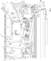
- Nachfolgend wird die Erfindung anhand bevorzugter Ausführungsbeispiele und zugehörigen Zeichnungen näher erläutert. In den Zeichnungen zeigen:
- Fig. 1:
- eine perspektivische Ansicht des Antriebsstrangs eines Ladewagens und/oder einer Ballenpresse zum Antreiben der Aufnahmevorrichtung umfassend eine rotierende Stachelwalze und einen nachgeordneten Förderrotor, wobei als zentrales Eingangsgetriebe ein Umschlingungsgetriebe vorgesehen und die Überlastkupplung der seitlich angeordneten Abtriebswelle des Umschlingungsgetriebes zugeordnet ist, und
- Fig. 2:
- eine ausschnittsweise perspektivische Darstellung des Hauptantriebsstrangs eines Anbaugeräts wie Ladewagen oder Ballenpresse, mit einem zentralen Eingangsgetriebe in Form eines Winkelgetriebes, auf dessen Abtriebswellenstummel die zentrale Überlastkupplung sitzt.
- Wie
Figur 1 zeigt, kann das landwirtschaftliche Anbaugerät 1 zum Anbau an einen nicht gezeigten Schlepper als Erntemaschine ausgebildet sein, die als Arbeitsaggregate eine Aufnahmevorrichtung beispielsweise mit einer rotatorisch antreibbaren Stachelwalze zum Aufnehmen von Erntegut vom Boden sowie einen der Aufnahmevorrichtung nachgeordneten Förderrotor 2 umfassen kann, der den von der Aufnahmevorrichtung her kommenden Erntegutstrom durch einen Förderkanal hindurch in einen Funktionsraum des Anbaugeräts fördern kann. Der genannte Förderrotor 2 kann beispielsweise um eine liegende, sich quer zur Fahrtrichtung erstreckende Achse rotatorisch angetrieben werden. - Dem genannten Förderrotor 2 können weitere Arbeitsaggregate nachgeordnet sein, beispielsweise ein Kratzboden oder eine Abladedosierwalzeneinrichtung, wenn die Erntemaschine als Ladewagen ausgebildet ist. Bei Ausbildung als Ballenpresse können dem Förderrotor 2 weitere Arbeitsaggregate in Form von Umlenkwalzen und/oder Riemenantrieben im Bereich einer Ballenformkammer nachgeordnet sein.
- Die genannten Antriebsaggregate werden von einem mechanischen Antriebsstrang 3 angetrieben, der einen Hauptantriebsstrang 4 mit einem zentralen Eingangsgetriebe 5 umfasst, das über eine Gelenkwelle 6 an die Schlepperzapfwelle angeschlossen werden kann. Wie
Figur 1 zeigt, kann das zentrale Eingangsgetriebe 5 einen Eingangswellenstummel 7 aufweisen, der sich in einem Mittelabschnitt des Anbaugeräts 1, beispielsweise unter einer Deichsel liegend näherungsweise fahrtrichtungsparallel erstrecken kann. Auf den genannten Eingangswellenstummel 7 des zentralen Eingangsgetriebes 5 kann die genannte Gelenkswelle 6 aufgesteckt oder in anderer Weise drehfest, vorzugsweise formschlüssig befestigt werden. - Wie
Figur 1 zeigt, kann das zentrale Eingangsgetriebe 5 des Hauptantriebsstrangs 4 als Umschlingungsgetriebe beispielsweise in Form eines Riemengetriebes ausgebildet sein, dessen Eingangsrad 8 auf dem genannten Eingangswellenstummel 7 sitzen kann und dessen Abtriebsrad 9 an einer rechten oder linken Seite des Anbaugeräts 1 sitzen kann. Zwischen den genannten Eingangs- und Abtriebsrädern 8, 9 kann das Umschlingungsgetriebe weitere Umlenkräder wie beispielsweise eine Riemen- oder Kettenspanner aufweisen. - Die genannten Eingangs- und Abtriebsräder 8, 9 des zentralen Eingangsgetriebes können jeweils liegende, etwa in Fahrtrichtung weisende Drehachsen aufweisen, wobei unabhängig hiervon das genannte Umschlingungsgetriebe zumindest die halbe Maschinenbreite des Anbaugeräts 1 überbrücken kann.
- Wie
Figur 1 zeigt, kann unmittelbar nach dem Abtriebsrad 9 des zentralen Eingangsgetriebes 5 eine Überlastkupplung 10 vorgesehen sein, die drehfest direkt mit dem Abtriebsrad 9 bzw. dem damit gekoppelten Wellenstummel des zentralen Eingangsgetriebes 5 verbunden sein kann, sodass sich die Überlastkupplung 10 synchron mit der Abtriebsdrehzahl des Eingangsgetriebes 5 drehen kann. - Wie
Figur 1 zeigt, kann die Überlastkupplung 10 an derselben linken bzw. rechten Seite des Anbaugeräts 1 wie das Abtriebsrad 9 des Eingangsgetriebes 5 angeordnet sein und eine liegende, näherungsweise in Fahrtrichtung weisende Drehachse besitzen. - Insbesondere kann die Überlastkupplung 10 koaxial zur Drehachse des Abtriebsrads 9 angeordnet sein.
- Die Überlastkupplung 10 sitzt dabei immer noch im Hauptantriebsstrang und wird mit der vollen Antriebsleistung der Schlepperzapfwelle beaufschlagt, die lediglich durch die Verluste im Eingangsgetriebe 5 reduziert sein kann.
- Die genannte Überlastkupplung 10 ist die von der Schlepperzapfwelle her betrachtet erste Überlastsicherung im Antriebsstrang 3, wobei die Überlastkupplung 10 noch vor Verzweigungen des Antriebsstrang 3 in Nebenantriebsstränge sitzen kann.
- Wie
Figur 1 zeigt, kann sich der genannte Hauptantriebsstrang 4 über ein Verzweigungsgetriebe 11 verzweigen, das eingangsseitig von der Überlastkupplung 10 angetrieben wird. Das genannte Verzweigungsgetriebe 11 kann beispielsweise ein Winkelgetriebe umfassen, das den genannten Förderrotor 2 antreibt. Unabhängig hiervon kann das Verzweigungsgetriebe 11 einen Durchtrieb umfassen, um ein weiteres Arbeitsaggregat beispielsweise in Form eines heckseitig angetriebenen Abladedosiersystems anzutreiben. Gegebenenfalls kann von dem genannten Verzweigungsgetriebe 11 auch ein Nebenantriebsstrang zum Antreiben der Pickup bzw. der Stachelwalze der Aufnahmevorrichtung abgehen. Alternativ oder zusätzlich können andere Nebenantriebsstränge 12 zu anderen Arbeitsaggregaten der Erntemaschine führen, um letztere anzutreiben, beispielsweise einen Ladewagen-Kratzboden oder Ballenpressen-Formkammer-Elemente. - In den besagten Nebenantriebssträngen 12 können ggf. weitere Überlastkupplungen vorgesehen sein.
- Wie
Figur 2 zeigt, kann das zentrale Eingangsgetriebe 5 der Erntemaschine aber auch als Winkelgetriebe ausgebildet sein, dessen Eingangswellenstummel sich ähnlich wie zuvor beschrieben liegend, näherungsweise fahrtrichtungsparallel im Mittelabschnitt des Anbaugeräts 1, beispielsweise unter einer Deichsel, erstrecken kann. - Die Abtriebswelle 13 bzw. der Abtriebswellenstummel des Winkelgetriebes kann sich liegend quer zur Fahrtrichtung erstrecken, um eine Antriebswelle 14 anzutreiben, die zu einem seitlich angeordneten Verteilergetriebe bzw. Verzweigungsgetriebe 11 führen kann, das in der vorgenannten Weise beispielsweise den Förderrotor 2 antreiben und über weitere, abgehende Abtriebs- oder Durchtriebswellen weitere Arbeitsaggregate antreiben bzw. die Antriebsleistung in entsprechende Nebenantriebsstränge 12 einspeisen kann.
- Wie
Figur 2 zeigt, kann die Überlastkupplung 10 unmittelbar an dem Winkelgetriebe angeordnet sein, beispielsweise direkt auf dessen Abtriebswellenstummel 13 sitzen und abtriebsseitig wiederum mit der Antriebswelle 14 gekoppelt sein, wobei die Antriebswelle 14 beispielsweise koaxial zur Abtriebswelle der Überlastkupplung angeordnet bzw. direkt damit verbunden sein kann. - Die Überlastkupplung 10 kann vorteilhafterweise als Nockenschaltkupplung ausgebildet sein, wobei aber auch andere Überlastkupplungs-Bauformen in Betracht kommen, beispielsweise reibschlüssig arbeitende Überlastsicherungskupplungen oder Scherbolzenkupplungen.
Claims (12)
- Landwirtschaftliches Anbaugerät zum Anbau an einen Schlepper, mit einem Antriebsstrang (3) zum Antreiben von Arbeitsaggregaten des Anbaugeräts einschließlich eines Arbeitsrotors (2), wobei der Antriebsstrang (3) ein zentrales Eingangsgetriebe (5), das über eine Gelenkwelle (6) an die Zapfwelle des Schleppers anschließbar ist, sowie eine Überlastkupplung (10) aufweist, die nach dem zentralen Eingangsgetriebe (5), vorgesehen ist und zumindest den genannten Arbeitsrotor (2) absichert, wobei der genannte Antriebsstrang (3) einen Hauptantriebsstrang (4), in dem das zentrale Eingangsgetriebe (5) vorgesehen ist, und vom Hauptantriebsstrang (4) zu den Arbeitsaggregaten abzweigende Nebenantriebsstränge (12) aufweist, dadurch gekennzeichnet, dass die genannte Überlastkupplung (10) noch im Hauptantriebsstrang (4) vor den abzweigenden Nebenantriebssträngen (12) vorgesehen ist.
- Landwirtschaftliches Anbaugerät nach dem vorhergehenden Anspruch, wobei der genannte Arbeitsrotor (2) ein Hauptarbeitsrotor des Anbaugeräts ist, der im Arbeitsbetrieb einen höheren Antriebsenergieverbrauch als andere Arbeitsaggregate aufweist und/oder im Arbeitsbetrieb permanent läuft und/oder längere Zeit und/oder häufiger läuft als andere Arbeitsaggregate des Anbaugeräts.
- Landwirtschaftliches Anbaugerät nach einem der vorhergehenden Ansprüche, wobei das zentrale Eingangsgetriebe (5) ein Umschlingungsgetriebe ist, dessen Eingangsrad (8) direkt mit der Gelenkwelle (6) drehfest verbunden ist und ein Abtriebsrad (9) besitzt, das mit dem Kupplungseingang der Überlastkupplung (10) drehfest verbunden ist.
- Landwirtschaftliches Anbaugerät nach dem vorhergehenden Anspruch, wobei das Umschlingungsgetriebe sich über zumindest die halbe Maschinenbreite des Anbaugeräts (1) erstreckt, wobei das Abtriebsrad (9) an einer rechten oder linken Seite des Anbaugeräts (1) angeordnet ist und die Überlastkupplung (10) unmittelbar nach dem genannten Abtriebsrad (9) auf derselben Maschinenseite wie das Abtriebsrad (9) angeordnet ist.
- Landwirtschaftliches Anbaugerät nach einem der beiden vorhergehenden Ansprüche, wobei das Abtriebsrad (9) und die Überlastkupplung (10) eine liegende, zumindest näherungsweise fahrtrichtungsparallele Drehachse besitzen und/oder zueinander koaxiale Drehachsen aufweisen.
- Landwirtschaftliches Anbaugerät nach einem der vorhergehenden Ansprüche, wobei zwischen der Überlastkupplung (10) und dem Abtriebsrad (9) des zentralen Eingangsgetriebes (5) lediglich ein Drehlager zum drehbaren Abstützen des Abtriebsrads (9) des zentralen Eingangsgetriebes (5) vorgesehen ist.
- Landwirtschaftliches Anbaugerät nach Anspruch 1, wobei das zentrale Eingangsgetriebe (5) ein Zahnradgetriebe, insbesondere ein Winkelgetriebe ist, wobei die Überlastkupplung (10) mit ihrem Kupplungseingang drehfest mit der Abtriebswelle des Zahnradgetriebes gekoppelt ist.
- Landwirtschaftliches Anbaugerät nach dem vorhergehenden Anspruch, wobei die Überlastkupplung (10) benachbart zum zentralen Eingangsgetriebe (5) in einem Mittelabschnitt des Anbaugeräts beabstandet von dessen linken und rechten Seiten angeordnet ist.
- Landwirtschaftliches Anbaugerät nach einem der beiden vorhergehenden Ansprüche, wobei eine Abtriebswelle (13) des zentralen Eingangsgetriebes (5) und die Überlastkupplung (10) jeweils eine liegende, quer zur Fahrtrichtung angeordnete Drehachse besitzen und/oder zueinander koaxiale Drehachsen besitzen.
- Landwirtschaftliches Anbaugerät nach einem der vorhergehenden Ansprüche, wobei zumindest eine weitere Überlastkupplung in zumindest einem Nebenantriebsstrang (12), der von dem Hauptantriebsstrang (4) abzweigt, vorgesehen ist.
- Landwirtschaftliches Anbaugerät nach einem der vorhergehenden Ansprüche, wobei das Anbaugerät (1) als Ladewagen oder Ballenpresse ausgebildet ist und als Arbeitsaggregat eine Aufnahmevorrichtung mit einer rotatorisch antreibbaren Stachelwalze zum Aufnehmen von Erntegut vom Boden sowie einen Förderrotor (2) zum Weiterfördern des vom Boden aufgenommenen Ernteguts in einen Funktionsraum, der einen Ladespeicher oder eine Ballenformkammer bildet, aufweist, wobei die Überlastkupplung (10) vor einem Verzweigungs- und/oder Durchgangsgetriebe (11) zum Antreiben des genannten Förderrotors (2) sowie zumindest eines weiteren Arbeitsaggregats angeordnet ist.
- Landwirtschaftliches Anbaugerät nach einem der vorhergehenden Ansprüche, wobei die Überlastkupplung (10) im Hauptantriebsstrang (4) von der vollen Zapfwellenantriebsleistung des Schleppers abzüglich etwaigen Verlusten im zentralen Eingangsgetriebe (5) beaufschlagbar ist.
Applications Claiming Priority (2)
| Application Number | Priority Date | Filing Date | Title |
|---|---|---|---|
| DE202021101208 | 2021-03-10 | ||
| DE202021102546.8U DE202021102546U1 (de) | 2021-03-10 | 2021-05-11 | Landwirtschaftliches Anbaugerät |
Publications (2)
| Publication Number | Publication Date |
|---|---|
| EP4056004A1 EP4056004A1 (de) | 2022-09-14 |
| EP4056004B1 true EP4056004B1 (de) | 2024-07-24 |
Family
ID=82321009
Family Applications (1)
| Application Number | Title | Priority Date | Filing Date |
|---|---|---|---|
| EP22158592.0A Active EP4056004B1 (de) | 2021-03-10 | 2022-02-24 | Landwirtschaftliches anbaugerät |
Country Status (2)
| Country | Link |
|---|---|
| EP (1) | EP4056004B1 (de) |
| DE (1) | DE202021102546U1 (de) |
Family Cites Families (8)
| Publication number | Priority date | Publication date | Assignee | Title |
|---|---|---|---|---|
| DE29504531U1 (de) * | 1995-03-16 | 1995-06-08 | Claas OHG beschränkt haftende offene Handelsgesellschaft, 33428 Harsewinkel | Kolbensammelpresse für landwirtschaftliches Erntegut |
| DE19701421A1 (de) | 1997-01-17 | 1998-07-23 | Welger Geb | Rundballenpresse für landwirtschaftliche Halmgüter |
| DE19718830A1 (de) * | 1997-05-05 | 1998-11-12 | Claas Usines France | Überwachungs- und Steuerungssystem zur Regelung der Arbeitsfunktionen einer Ballenpresse |
| DE19831506C2 (de) * | 1998-07-14 | 2002-04-04 | Lely Maschinenfabrik Gmbh | Ballenpresse für landwirtschaftliche Erntegüter zur Erzeugung rechteckiger Ballen |
| DE10145407C2 (de) | 2001-09-14 | 2003-11-13 | Walterscheid Gmbh Gkn | Antriebsanordnung und Verfahren zum Festsetzen mindestens eines Arbeitsaggregats |
| DE102011055206A1 (de) | 2011-11-10 | 2013-05-16 | Gkn Walterscheid Gmbh | Antriebsstrang zwischen der Zapfwelle einer Zugmaschine und dem Antriebsgetriebe eines Anhängerfahrzeuges |
| DE102018129598B4 (de) * | 2018-11-23 | 2026-03-12 | Pöttinger Landtechnik Gmbh | Landwirtschaftliche Erntemaschine |
| US11589514B2 (en) * | 2019-10-30 | 2023-02-28 | Cnh Industrial America Llc | Pickup drive system for an agricultural baler |
-
2021
- 2021-05-11 DE DE202021102546.8U patent/DE202021102546U1/de active Active
-
2022
- 2022-02-24 EP EP22158592.0A patent/EP4056004B1/de active Active
Also Published As
| Publication number | Publication date |
|---|---|
| EP4056004A1 (de) | 2022-09-14 |
| DE202021102546U1 (de) | 2022-06-15 |
Similar Documents
| Publication | Publication Date | Title |
|---|---|---|
| EP1609351B1 (de) | Erntevorsatzantrieb | |
| EP2384612B1 (de) | Antriebsanordnung für einen Erntevorsatz einer Erntemaschine | |
| EP1862057B1 (de) | Vorsatzgerät zum Ernten von stängeligem Erntegut | |
| EP2145524B1 (de) | Landwirtschaftliche Erntemaschine | |
| EP2281434B1 (de) | Vorsatzgerät mit Querfördereinrichtung und Drehzahlanpassung | |
| EP3016494B1 (de) | Landwirtschaftliches gerät und verfahren zur bearbeitung von pflanzenstoppeln | |
| DE10234741A1 (de) | Anlenkung eines Seitenmähwerks und seiner Zusatzeinrichtungen an ein Tragwerk zur Ankopplung an einen Traktor oder an ein Trägerfahrzeug | |
| EP1287731A1 (de) | Einrichtung zum Antrieb einer Austrageinrichtung einer landwirtschaftlichen Erntemaschine | |
| EP1317879B1 (de) | Maschine zum Mähen von stängelartigem Erntegut | |
| EP1864567B1 (de) | Gutaufnehmer | |
| EP4056004B1 (de) | Landwirtschaftliches anbaugerät | |
| DE102017006804B4 (de) | Kreiselschwader | |
| EP1767085A1 (de) | Maschine zur Ernte stängelartiger Pflanzen | |
| BE1022788B1 (de) | Maschine zum mähen von stängelartigem erntegut mit sukzessive ansteigender querfördergeschwindigkeit | |
| DE102020203474A1 (de) | Mulchgerät zur Bearbeitung von Pflanzenstoppeln | |
| EP0950347A1 (de) | Heuwerbungsmaschine | |
| EP1932415B1 (de) | Vorrichtung mit einer ersten und einer zweiten Arbeitseinheit | |
| DE102016103362B3 (de) | Halmgutfördervorrichtung | |
| DE102005062266B4 (de) | Förderer | |
| EP1566090A1 (de) | Maschine zum Mähen von stängelartigem Erntegut | |
| DE102005009939B4 (de) | Erntevorsatz für landwirtschaftliche Erntemaschinen | |
| EP4000376A1 (de) | Anbauhäcksler mit einem getriebe, das an eine zapfwelle eines schleppers anschliessbar ist, arbeitszug mit dem anbauhäcksler und dem schlepper, und verfahren zum einstellen eines einstellwinkels | |
| DE20212885U1 (de) | Landwirtschaftliche Mähguterntegruppe | |
| EP4295668A1 (de) | Einzugsanordnung für eine landmaschine | |
| DE20112476U1 (de) | Frontbandrechengerät |
Legal Events
| Date | Code | Title | Description |
|---|---|---|---|
| PUAI | Public reference made under article 153(3) epc to a published international application that has entered the european phase |
Free format text: ORIGINAL CODE: 0009012 |
|
| STAA | Information on the status of an ep patent application or granted ep patent |
Free format text: STATUS: THE APPLICATION HAS BEEN PUBLISHED |
|
| AK | Designated contracting states |
Kind code of ref document: A1 Designated state(s): AL AT BE BG CH CY CZ DE DK EE ES FI FR GB GR HR HU IE IS IT LI LT LU LV MC MK MT NL NO PL PT RO RS SE SI SK SM TR |
|
| STAA | Information on the status of an ep patent application or granted ep patent |
Free format text: STATUS: REQUEST FOR EXAMINATION WAS MADE |
|
| 17P | Request for examination filed |
Effective date: 20230314 |
|
| RBV | Designated contracting states (corrected) |
Designated state(s): AL AT BE BG CH CY CZ DE DK EE ES FI FR GB GR HR HU IE IS IT LI LT LU LV MC MK MT NL NO PL PT RO RS SE SI SK SM TR |
|
| GRAP | Despatch of communication of intention to grant a patent |
Free format text: ORIGINAL CODE: EPIDOSNIGR1 |
|
| STAA | Information on the status of an ep patent application or granted ep patent |
Free format text: STATUS: GRANT OF PATENT IS INTENDED |
|
| RIC1 | Information provided on ipc code assigned before grant |
Ipc: A01F 15/08 20060101ALI20240311BHEP Ipc: A01D 78/02 20060101ALI20240311BHEP Ipc: A01D 69/08 20060101ALI20240311BHEP Ipc: A01D 69/00 20060101ALI20240311BHEP Ipc: A01D 43/00 20060101ALI20240311BHEP Ipc: A01B 71/02 20060101ALI20240311BHEP Ipc: A01B 33/16 20060101ALI20240311BHEP Ipc: A01B 33/08 20060101ALI20240311BHEP Ipc: A01B 33/00 20060101AFI20240311BHEP |
|
| INTG | Intention to grant announced |
Effective date: 20240408 |
|
| GRAS | Grant fee paid |
Free format text: ORIGINAL CODE: EPIDOSNIGR3 |
|
| GRAA | (expected) grant |
Free format text: ORIGINAL CODE: 0009210 |
|
| STAA | Information on the status of an ep patent application or granted ep patent |
Free format text: STATUS: THE PATENT HAS BEEN GRANTED |
|
| AK | Designated contracting states |
Kind code of ref document: B1 Designated state(s): AL AT BE BG CH CY CZ DE DK EE ES FI FR GB GR HR HU IE IS IT LI LT LU LV MC MK MT NL NO PL PT RO RS SE SI SK SM TR |
|
| REG | Reference to a national code |
Ref country code: GB Ref legal event code: FG4D Free format text: NOT ENGLISH |
|
| REG | Reference to a national code |
Ref country code: CH Ref legal event code: EP |
|
| REG | Reference to a national code |
Ref country code: DE Ref legal event code: R096 Ref document number: 502022001271 Country of ref document: DE |
|
| REG | Reference to a national code |
Ref country code: IE Ref legal event code: FG4D Free format text: LANGUAGE OF EP DOCUMENT: GERMAN |
|
| REG | Reference to a national code |
Ref country code: NL Ref legal event code: FP |
|
| REG | Reference to a national code |
Ref country code: LT Ref legal event code: MG9D |
|
| PG25 | Lapsed in a contracting state [announced via postgrant information from national office to epo] |
Ref country code: PT Free format text: LAPSE BECAUSE OF FAILURE TO SUBMIT A TRANSLATION OF THE DESCRIPTION OR TO PAY THE FEE WITHIN THE PRESCRIBED TIME-LIMIT Effective date: 20241125 |
|
| PG25 | Lapsed in a contracting state [announced via postgrant information from national office to epo] |
Ref country code: PT Free format text: LAPSE BECAUSE OF FAILURE TO SUBMIT A TRANSLATION OF THE DESCRIPTION OR TO PAY THE FEE WITHIN THE PRESCRIBED TIME-LIMIT Effective date: 20241125 |
|
| PG25 | Lapsed in a contracting state [announced via postgrant information from national office to epo] |
Ref country code: NO Free format text: LAPSE BECAUSE OF FAILURE TO SUBMIT A TRANSLATION OF THE DESCRIPTION OR TO PAY THE FEE WITHIN THE PRESCRIBED TIME-LIMIT Effective date: 20241024 |
|
| PG25 | Lapsed in a contracting state [announced via postgrant information from national office to epo] |
Ref country code: PL Free format text: LAPSE BECAUSE OF FAILURE TO SUBMIT A TRANSLATION OF THE DESCRIPTION OR TO PAY THE FEE WITHIN THE PRESCRIBED TIME-LIMIT Effective date: 20240724 Ref country code: GR Free format text: LAPSE BECAUSE OF FAILURE TO SUBMIT A TRANSLATION OF THE DESCRIPTION OR TO PAY THE FEE WITHIN THE PRESCRIBED TIME-LIMIT Effective date: 20241025 Ref country code: FI Free format text: LAPSE BECAUSE OF FAILURE TO SUBMIT A TRANSLATION OF THE DESCRIPTION OR TO PAY THE FEE WITHIN THE PRESCRIBED TIME-LIMIT Effective date: 20240724 |
|
| PG25 | Lapsed in a contracting state [announced via postgrant information from national office to epo] |
Ref country code: BG Free format text: LAPSE BECAUSE OF FAILURE TO SUBMIT A TRANSLATION OF THE DESCRIPTION OR TO PAY THE FEE WITHIN THE PRESCRIBED TIME-LIMIT Effective date: 20240724 |
|
| PG25 | Lapsed in a contracting state [announced via postgrant information from national office to epo] |
Ref country code: LV Free format text: LAPSE BECAUSE OF FAILURE TO SUBMIT A TRANSLATION OF THE DESCRIPTION OR TO PAY THE FEE WITHIN THE PRESCRIBED TIME-LIMIT Effective date: 20240724 |
|
| PG25 | Lapsed in a contracting state [announced via postgrant information from national office to epo] |
Ref country code: IS Free format text: LAPSE BECAUSE OF FAILURE TO SUBMIT A TRANSLATION OF THE DESCRIPTION OR TO PAY THE FEE WITHIN THE PRESCRIBED TIME-LIMIT Effective date: 20241124 |
|
| PG25 | Lapsed in a contracting state [announced via postgrant information from national office to epo] |
Ref country code: HR Free format text: LAPSE BECAUSE OF FAILURE TO SUBMIT A TRANSLATION OF THE DESCRIPTION OR TO PAY THE FEE WITHIN THE PRESCRIBED TIME-LIMIT Effective date: 20240724 |
|
| PG25 | Lapsed in a contracting state [announced via postgrant information from national office to epo] |
Ref country code: RS Free format text: LAPSE BECAUSE OF FAILURE TO SUBMIT A TRANSLATION OF THE DESCRIPTION OR TO PAY THE FEE WITHIN THE PRESCRIBED TIME-LIMIT Effective date: 20241024 Ref country code: ES Free format text: LAPSE BECAUSE OF FAILURE TO SUBMIT A TRANSLATION OF THE DESCRIPTION OR TO PAY THE FEE WITHIN THE PRESCRIBED TIME-LIMIT Effective date: 20240724 |
|
| PG25 | Lapsed in a contracting state [announced via postgrant information from national office to epo] |
Ref country code: RS Free format text: LAPSE BECAUSE OF FAILURE TO SUBMIT A TRANSLATION OF THE DESCRIPTION OR TO PAY THE FEE WITHIN THE PRESCRIBED TIME-LIMIT Effective date: 20241024 Ref country code: PL Free format text: LAPSE BECAUSE OF FAILURE TO SUBMIT A TRANSLATION OF THE DESCRIPTION OR TO PAY THE FEE WITHIN THE PRESCRIBED TIME-LIMIT Effective date: 20240724 Ref country code: NO Free format text: LAPSE BECAUSE OF FAILURE TO SUBMIT A TRANSLATION OF THE DESCRIPTION OR TO PAY THE FEE WITHIN THE PRESCRIBED TIME-LIMIT Effective date: 20241024 Ref country code: LV Free format text: LAPSE BECAUSE OF FAILURE TO SUBMIT A TRANSLATION OF THE DESCRIPTION OR TO PAY THE FEE WITHIN THE PRESCRIBED TIME-LIMIT Effective date: 20240724 Ref country code: IS Free format text: LAPSE BECAUSE OF FAILURE TO SUBMIT A TRANSLATION OF THE DESCRIPTION OR TO PAY THE FEE WITHIN THE PRESCRIBED TIME-LIMIT Effective date: 20241124 Ref country code: HR Free format text: LAPSE BECAUSE OF FAILURE TO SUBMIT A TRANSLATION OF THE DESCRIPTION OR TO PAY THE FEE WITHIN THE PRESCRIBED TIME-LIMIT Effective date: 20240724 Ref country code: GR Free format text: LAPSE BECAUSE OF FAILURE TO SUBMIT A TRANSLATION OF THE DESCRIPTION OR TO PAY THE FEE WITHIN THE PRESCRIBED TIME-LIMIT Effective date: 20241025 Ref country code: FI Free format text: LAPSE BECAUSE OF FAILURE TO SUBMIT A TRANSLATION OF THE DESCRIPTION OR TO PAY THE FEE WITHIN THE PRESCRIBED TIME-LIMIT Effective date: 20240724 Ref country code: ES Free format text: LAPSE BECAUSE OF FAILURE TO SUBMIT A TRANSLATION OF THE DESCRIPTION OR TO PAY THE FEE WITHIN THE PRESCRIBED TIME-LIMIT Effective date: 20240724 Ref country code: BG Free format text: LAPSE BECAUSE OF FAILURE TO SUBMIT A TRANSLATION OF THE DESCRIPTION OR TO PAY THE FEE WITHIN THE PRESCRIBED TIME-LIMIT Effective date: 20240724 |
|
| PG25 | Lapsed in a contracting state [announced via postgrant information from national office to epo] |
Ref country code: DK Free format text: LAPSE BECAUSE OF FAILURE TO SUBMIT A TRANSLATION OF THE DESCRIPTION OR TO PAY THE FEE WITHIN THE PRESCRIBED TIME-LIMIT Effective date: 20240724 Ref country code: SM Free format text: LAPSE BECAUSE OF FAILURE TO SUBMIT A TRANSLATION OF THE DESCRIPTION OR TO PAY THE FEE WITHIN THE PRESCRIBED TIME-LIMIT Effective date: 20240724 Ref country code: RO Free format text: LAPSE BECAUSE OF FAILURE TO SUBMIT A TRANSLATION OF THE DESCRIPTION OR TO PAY THE FEE WITHIN THE PRESCRIBED TIME-LIMIT Effective date: 20240724 |
|
| PG25 | Lapsed in a contracting state [announced via postgrant information from national office to epo] |
Ref country code: EE Free format text: LAPSE BECAUSE OF FAILURE TO SUBMIT A TRANSLATION OF THE DESCRIPTION OR TO PAY THE FEE WITHIN THE PRESCRIBED TIME-LIMIT Effective date: 20240724 |
|
| PGFP | Annual fee paid to national office [announced via postgrant information from national office to epo] |
Ref country code: CH Payment date: 20250319 Year of fee payment: 4 |
|
| PG25 | Lapsed in a contracting state [announced via postgrant information from national office to epo] |
Ref country code: CZ Free format text: LAPSE BECAUSE OF FAILURE TO SUBMIT A TRANSLATION OF THE DESCRIPTION OR TO PAY THE FEE WITHIN THE PRESCRIBED TIME-LIMIT Effective date: 20240724 |
|
| REG | Reference to a national code |
Ref country code: DE Ref legal event code: R097 Ref document number: 502022001271 Country of ref document: DE |
|
| PG25 | Lapsed in a contracting state [announced via postgrant information from national office to epo] |
Ref country code: SK Free format text: LAPSE BECAUSE OF FAILURE TO SUBMIT A TRANSLATION OF THE DESCRIPTION OR TO PAY THE FEE WITHIN THE PRESCRIBED TIME-LIMIT Effective date: 20240724 Ref country code: IT Free format text: LAPSE BECAUSE OF FAILURE TO SUBMIT A TRANSLATION OF THE DESCRIPTION OR TO PAY THE FEE WITHIN THE PRESCRIBED TIME-LIMIT Effective date: 20240724 |
|
| PLBE | No opposition filed within time limit |
Free format text: ORIGINAL CODE: 0009261 |
|
| STAA | Information on the status of an ep patent application or granted ep patent |
Free format text: STATUS: NO OPPOSITION FILED WITHIN TIME LIMIT |
|
| 26N | No opposition filed |
Effective date: 20250425 |
|
| PG25 | Lapsed in a contracting state [announced via postgrant information from national office to epo] |
Ref country code: SE Free format text: LAPSE BECAUSE OF FAILURE TO SUBMIT A TRANSLATION OF THE DESCRIPTION OR TO PAY THE FEE WITHIN THE PRESCRIBED TIME-LIMIT Effective date: 20240724 |
|
| PG25 | Lapsed in a contracting state [announced via postgrant information from national office to epo] |
Ref country code: MC Free format text: LAPSE BECAUSE OF FAILURE TO SUBMIT A TRANSLATION OF THE DESCRIPTION OR TO PAY THE FEE WITHIN THE PRESCRIBED TIME-LIMIT Effective date: 20240724 |
|
| PG25 | Lapsed in a contracting state [announced via postgrant information from national office to epo] |
Ref country code: LU Free format text: LAPSE BECAUSE OF NON-PAYMENT OF DUE FEES Effective date: 20250224 |
|
| REG | Reference to a national code |
Ref country code: BE Ref legal event code: MM Effective date: 20250228 |
|
| PG25 | Lapsed in a contracting state [announced via postgrant information from national office to epo] |
Ref country code: BE Free format text: LAPSE BECAUSE OF NON-PAYMENT OF DUE FEES Effective date: 20250228 |
|
| PG25 | Lapsed in a contracting state [announced via postgrant information from national office to epo] |
Ref country code: IE Free format text: LAPSE BECAUSE OF NON-PAYMENT OF DUE FEES Effective date: 20250224 |
|
| PGFP | Annual fee paid to national office [announced via postgrant information from national office to epo] |
Ref country code: NL Payment date: 20260219 Year of fee payment: 5 |
|
| PGFP | Annual fee paid to national office [announced via postgrant information from national office to epo] |
Ref country code: DE Payment date: 20260218 Year of fee payment: 5 |
|
| PGFP | Annual fee paid to national office [announced via postgrant information from national office to epo] |
Ref country code: AT Payment date: 20260301 Year of fee payment: 5 |
|
| REG | Reference to a national code |
Ref country code: CH Ref legal event code: U11 Free format text: ST27 STATUS EVENT CODE: U-0-0-U10-U11 (AS PROVIDED BY THE NATIONAL OFFICE) Effective date: 20260416 |
|
| PGFP | Annual fee paid to national office [announced via postgrant information from national office to epo] |
Ref country code: FR Payment date: 20260225 Year of fee payment: 5 |