EP4056035A1 - Träger, vakuumierungsvorrichtung und system zur kryokonservierung von gewebe - Google Patents
Träger, vakuumierungsvorrichtung und system zur kryokonservierung von gewebe Download PDFInfo
- Publication number
- EP4056035A1 EP4056035A1 EP20905934.4A EP20905934A EP4056035A1 EP 4056035 A1 EP4056035 A1 EP 4056035A1 EP 20905934 A EP20905934 A EP 20905934A EP 4056035 A1 EP4056035 A1 EP 4056035A1
- Authority
- EP
- European Patent Office
- Prior art keywords
- tissue
- carrier
- freezing
- contact
- cavity
- Prior art date
- Legal status (The legal status is an assumption and is not a legal conclusion. Google has not performed a legal analysis and makes no representation as to the accuracy of the status listed.)
- Withdrawn
Links
Images


Classifications
-
- A—HUMAN NECESSITIES
- A01—AGRICULTURE; FORESTRY; ANIMAL HUSBANDRY; HUNTING; TRAPPING; FISHING
- A01N—PRESERVATION OF BODIES OF HUMANS OR ANIMALS OR PLANTS OR PARTS THEREOF; BIOCIDES, e.g. AS DISINFECTANTS, AS PESTICIDES OR AS HERBICIDES; PEST REPELLANTS OR ATTRACTANTS; PLANT GROWTH REGULATORS
- A01N1/00—Preservation of bodies of humans or animals, or parts thereof
- A01N1/10—Preservation of living parts
- A01N1/14—Mechanical aspects of preservation; Apparatus or containers therefor
- A01N1/146—Non-refrigerated containers specially adapted for transporting or storing living parts whilst preserving
- A01N1/147—Carriers for immersion in cryogenic fluid for slow freezing or vitrification
-
- A—HUMAN NECESSITIES
- A01—AGRICULTURE; FORESTRY; ANIMAL HUSBANDRY; HUNTING; TRAPPING; FISHING
- A01N—PRESERVATION OF BODIES OF HUMANS OR ANIMALS OR PLANTS OR PARTS THEREOF; BIOCIDES, e.g. AS DISINFECTANTS, AS PESTICIDES OR AS HERBICIDES; PEST REPELLANTS OR ATTRACTANTS; PLANT GROWTH REGULATORS
- A01N1/00—Preservation of bodies of humans or animals, or parts thereof
- A01N1/10—Preservation of living parts
- A01N1/14—Mechanical aspects of preservation; Apparatus or containers therefor
- A01N1/142—Apparatus
-
- A—HUMAN NECESSITIES
- A01—AGRICULTURE; FORESTRY; ANIMAL HUSBANDRY; HUNTING; TRAPPING; FISHING
- A01N—PRESERVATION OF BODIES OF HUMANS OR ANIMALS OR PLANTS OR PARTS THEREOF; BIOCIDES, e.g. AS DISINFECTANTS, AS PESTICIDES OR AS HERBICIDES; PEST REPELLANTS OR ATTRACTANTS; PLANT GROWTH REGULATORS
- A01N1/00—Preservation of bodies of humans or animals, or parts thereof
- A01N1/10—Preservation of living parts
- A01N1/14—Mechanical aspects of preservation; Apparatus or containers therefor
- A01N1/142—Apparatus
- A01N1/144—Apparatus for temperature control, e.g. refrigerators or freeze-drying apparatus
-
- A—HUMAN NECESSITIES
- A61—MEDICAL OR VETERINARY SCIENCE; HYGIENE
- A61J—CONTAINERS SPECIALLY ADAPTED FOR MEDICAL OR PHARMACEUTICAL PURPOSES; DEVICES OR METHODS SPECIALLY ADAPTED FOR BRINGING PHARMACEUTICAL PRODUCTS INTO PARTICULAR PHYSICAL OR ADMINISTERING FORMS; DEVICES FOR ADMINISTERING FOOD OR MEDICINES ORALLY; BABY COMFORTERS; DEVICES FOR RECEIVING SPITTLE
- A61J3/00—Devices or methods specially adapted for bringing pharmaceutical products into particular physical or administering forms
-
- B—PERFORMING OPERATIONS; TRANSPORTING
- B01—PHYSICAL OR CHEMICAL PROCESSES OR APPARATUS IN GENERAL
- B01L—CHEMICAL OR PHYSICAL LABORATORY APPARATUS FOR GENERAL USE
- B01L3/00—Containers or dishes for laboratory use, e.g. laboratory glassware; Droppers
- B01L3/50—Containers for the purpose of retaining a material to be analysed, e.g. test tubes
- B01L3/502—Containers for the purpose of retaining a material to be analysed, e.g. test tubes with fluid transport, e.g. in multi-compartment structures
- B01L3/5027—Containers for the purpose of retaining a material to be analysed, e.g. test tubes with fluid transport, e.g. in multi-compartment structures by integrated microfluidic structures, i.e. dimensions of channels and chambers are such that surface tension forces are important, e.g. lab-on-a-chip
- B01L3/502761—Containers for the purpose of retaining a material to be analysed, e.g. test tubes with fluid transport, e.g. in multi-compartment structures by integrated microfluidic structures, i.e. dimensions of channels and chambers are such that surface tension forces are important, e.g. lab-on-a-chip specially adapted for handling suspended solids or molecules independently from the bulk fluid flow, e.g. for trapping or sorting beads or physically stretching molecules
-
- G—PHYSICS
- G01—MEASURING; TESTING
- G01N—INVESTIGATING OR ANALYSING MATERIALS BY DETERMINING THEIR CHEMICAL OR PHYSICAL PROPERTIES
- G01N1/00—Sampling; Preparing specimens for investigation
- G01N1/28—Preparing specimens for investigation including physical details of (bio-)chemical methods covered elsewhere, e.g. G01N33/50, C12Q
- G01N1/42—Low-temperature sample treatment, e.g. cryofixation
-
- B—PERFORMING OPERATIONS; TRANSPORTING
- B01—PHYSICAL OR CHEMICAL PROCESSES OR APPARATUS IN GENERAL
- B01L—CHEMICAL OR PHYSICAL LABORATORY APPARATUS FOR GENERAL USE
- B01L2300/00—Additional constructional details
- B01L2300/18—Means for temperature control
- B01L2300/1894—Cooling means; Cryo cooling
Definitions
- the present application relates to the field of medical devices, and more particularly to a carrier, a vacuumizing device, and a tissue cryopreservation system.
- the cryopreservation of the ovarian tissue is a topic of great concern in the fields of assisted reproduction and tumors.
- the cryopreservation of the ovarian tissue is one of important ways for preserving fertility.
- the low-temperature preservation method of the ovarian tissue mainly includes slow cryopreservation and vitrification cryopreservation.
- the slow cryopreservation needs to use a special programmed cooling equipment, which takes a longer cooling time and have the complex operation, and ice crystals inside cells are easily formed in the cooling process to cause irreversible damage to the ovarian tissue, so that the application and popularization of the slow cryopreservation of the ovarian tissue are limited clinically.
- the ovarian tissues are placed in a high-concentration protective agent for vitrification cryopreservation, then the ovarian tissues are placed in liquid nitrogen for cooling and preservation by loading through a carrier, so that the tissues can be rapidly cooled and form a glassy state, and ice crystals inside cells are prevented from being formed.
- research shows that the frozen effect of the vitrification cryopreservation of ovarian tissue is superior to that of the slow cryopreservation of ovarian tissue, and the vitrification cryopreservation is simple to operate, short in time consumption, and good in clinical application prospect.
- the vitrification cryopreservation needs a faster cooling rate and a high-concentration protective agent, and the two factors are mutually influenced. Increasing the cooling rate can reduce the concentration of the protective agent required by vitrification.
- the cooling rate is related to many factors such as the volume of the residual solution of the tissue, the heat transfer resistance between liquid nitrogen, the material and thickness of the carrier, and the like.
- a conventional carrier for the vitrification cryopreservation of ovarian tissues mainly includes a frozen straw, a needle-punched carrier, or a stainless steel sheet and the like.
- the frozen straw can only cryopreserve a small volume of ovarian tissues, follicle loss can be caused in the process of shearing, crushing and cutting the tissues, and the hormone secretion after transplantation is maintained for a short time.
- a common needle-punched freezing carrier can cause irreversible mechanical damage to the ovarian tissue, and the tissue is easy to fall off from a steel needle during operation. After the stainless steel sheet carrier is loaded, excess solution attached to tissues is difficult to remove, the cryopreservation volume is large, which affects the cooling rate during freezing, and is not conducive to vitrification. Therefore, not removing excess liquid after loading the protective agent has a greater impact on the freezing rate.
- closed cryopreservation carriers are also commonly used in clinical medicine to prevent cross infection caused by pathogenic bacteria existing in liquid nitrogen.
- Most of the existing closing methods are a sleeve method and a membrane coating method, but the heat transfer resistance of air existing in gaps between a sleeve and a tissue, and between a membrane and a tissue is large, which affects the cooling rate of the tissue, and ice crystals can be formed in the tissue, resulting in large ice crystal damage.
- a plurality of samples need to be cryopreserved for later use.
- cryopreservation cannot be achieved, one patient needs a plurality of carriers for preserving the tissues, but the unit price of the carriers is high, resulting in high cryopreservation costs.
- the carrier with the tissue also needs to be placed in liquid nitrogen for unified management and preservation, and in this case, patient information needs to be handwritten or printed, and pasted outside the carrier, but the information is difficult to be confirmed when the carrier is taken, and the management is inconvenient.
- An object of the present application is to provide a carrier, a vacuumizing device, and a tissue cryopreservation system, so as to improve the cooling rate of vitrification cryopreservation of tissue, especially ovarian tissue, and prevent the formation of ice crystals inside the tissue to cause irreversible damage to the tissue.
- An object of the present application is to provide a carrier, a vacuumizing device, and a tissue cryopreservation system, so as to solve problems of high price of an existing carrier, inability to achieve high-throughput cryopreservation, and inconvenience in managing patient information.
- a carrier for cryopreservation of tissue is provided with at least one freezing cavity.
- the freezing cavity is provided with a plurality of flow guiding holes on a contact surface thereof in contact with the tissue.
- the plurality of flow guiding holes are configured to vacuum liquid on a surface of the tissue and enable the liquid to be discharged out of the freezing cavity through the plurality of flow guiding holes.
- the contact surface of the freezing cavity in contact with the tissue includes a bottom surface and a side surface adjacent to the bottom surface, and the side surface has a slope relative to the bottom surface.
- a cross-section of the contact surface of the freezing cavity in contact with the tissue is U-shaped, semicircular, or semi-elliptical.
- the carrier is provided with a plurality of freezing cavities, the plurality of freezing cavities are arranged at intervals along an axial direction of the carrier.
- the flow guiding hole has an inlet disposed on the contact surface of the freezing cavity in contact with the tissue and an outlet far away from the contact surface of the freezing cavity in contact with the tissue, the inlet has a cross-sectional area greater than that of the outlet.
- a cross-sectional area of the flow guiding hole gradually decreases from the inlet to the outlet.
- the carrier is provided with an information recorder thereon, the information recorder records readable patient information.
- the information recorder includes a two-dimensional code and/or a radio frequency identification device (RFID) chip.
- RFID radio frequency identification device
- a vacuumizing device is provided, and is configured to cooperate with the carrier described in any one of the technical solutions of the present application to vacuum liquid on a surface of a tissue.
- the vacuumizing device includes a mounting seat and a vacuum pump.
- the mounting seat is provided with a placement cavity for the carrier to be placed.
- the vacuum pump is in communication with the plurality of flow guiding holes on the carrier through the placement cavity so as to vacuum the liquid on the surface of the tissue placed on the carrier.
- the vacuumizing device further includes a membrane configured to vacuum-package the carrier.
- the membrane is provided with an opening
- the mounting seat is provided with a vacuum packaging port thereon
- the vacuum packaging port is connected to the opening and the vacuum pump, respectively.
- a shape of the placement cavity matches a shape of the carrier.
- a tissue cryopreservation system which includes a carrier described in any one of the technical solutions of the present application and a vacuumizing device described in any one of the technical solutions of the present application.
- the tissue cryopreservation system further includes a water absorbent structure arranged between the carrier and the placement cavity, the water absorbent structure is configured to absorb liquid discharged from the flow guiding holes.
- the tissue is ovarian tissue.
- the carrier, the vacuumizing device, and the tissue cryopreservation system of the present application have the following advantages.
- the vacuumizing device can be used to vacuum excess liquid on the surface of the tissue, such as the protective agent, through the plurality of flow guiding holes, and discharge the excess liquid out of the freezing cavity along the flow guiding holes. In doing so, toxic damage to the tissue due to prolonged contact with high-concentration protective agent can be prevented. In addition, the excess liquid is discharged out of the freezing cavity, so that the cryopreservation volume of the tissue can be reduced, and the cooling rate during freezing is increased.
- the information recorder on the carrier, for example the RFID chip and the two-dimensional code, not only can the patient information be recorded accurately to facilitate the quick information confirmation during extraction and avoid the potential damage to the tissue sample caused by prolonged staying under ambient temperature, but also the double guarantee of confirming the patient information can be provided to avoid the ethical and moral problems caused by information errors.
- the contact surface of the freezing cavity in contact with the tissue is provided with the bottom surface and the side surface which is adjacent to the bottom surface, and the side surface has a certain slope relative to the bottom surface, that is, the surface on which the tissue is placed has a certain slope.
- the cross-section of the contact surface of the freezing cavity in contact with the tissue can be U-shaped, semicircular, or semi-elliptical, so that the liquid on the surface of the tissue can form a downward gathering effect by its own gravity, thereby improving the efficiency of liquid exudation.
- the carrier is also vacuum-packaged by the membrane, so that the membrane is close to the tissue, which greatly reduces the heat transfer resistance between the liquid nitrogen and the tissue, can further improve the cooling rate during freezing, facilitate the reduction of the formation of ice crystals, and improve the cryopreservation effect.
- the core idea of the present application is to provide a carrier, a vacuumizing device, and a tissue cryopreservation system, which aims to reduce the cryopreservation volume and increase the cooling rate by removing the excess liquid on the tissue surface by vacuuming.
- the carrier can be subjected to vacuum packaging by utilizing the membrane, so that the membrane for sealing is close to the tissue, which greatly reduces the heat transfer resistance between the liquid nitrogen and the tissue, improves the cooling rate, and prevents the irreversible damage to the tissue caused by the formation of ice crystals inside the tissue.
- the carrier, the vacuumizing device, and the tissue cryopreservation system provided by an embodiment of the present application will be described below with reference to FIGS. 1 to 5 .
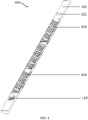
- FIG. 1 and FIG. 2 are a perspective view and a front view of a carrier 100 according to an embodiment of the present application, respectively.
- the carrier 100 has at least one freezing cavity 103, and the freezing cavity 103 can be used to load tissue, especially ovarian tissue.
- a plurality of flow guiding holes 104 are provided on a contact surface of the freezing cavity 103 in contact with the tissue.
- the freezing cavity is air permeable.
- the flow guiding hole 104 has an inlet disposed on the contact surface of the freezing cavity 103 in contact with the tissue and an outlet far away from the contact surface of the freezing cavity 103 in contact with the tissue.
- a cross-sectional area of the inlet is larger than that of the outlet, so that the flow guiding hole 104 has a structure that is wide at the top and narrow at the bottom.
- a diameter of the flow guiding hole 104 near the tissue is larger, so that an inlet section of the flow guiding hole 104 in contact with the tissue is wider, so as to increase the contact surface and collect liquid in a large area, and an outlet section thereof far away from the tissue is narrower, which is beneficial to improving liquid discharge efficiency.
- the cross-sectional area of the flow guiding hole 104 gradually decreases from the inlet to the outlet.
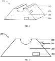
- This embodiment also provides a vacuumizing device 200, referring to FIG. 3 and FIG. 4 , which are a perspective view and a front view of the vacuumizing device 200, respectively.
- the vacuumizing device 200 is used to cooperate with the carrier 100 and includes a mounting seat 201.
- the mounting seat 201 is provided with a placement cavity 202, and the placement cavity 202 is used for the carrier 100 to be placed.
- a suction port corresponding to the outlet of the flow guiding hole of the carrier 100 may be provided in the placement cavity 202.
- the vacuumizing device 200 further includes a power equipment for vacuumizing, such as a vacuum pump 204.
- the power equipment may communicate with the plurality of flow guiding holes 104 on the carrier 100 through the suction port of the placement cavity 202 to vacuum the liquid from the surface of the tissue placed on the carrier.
- the vacuum pump 204 can vacuum from the bottom of the carrier 100, and the air is flowed by using a pressure difference between an upper side and a lower side of the carrier 100, so as to drive the excess liquid on the surface of tissue above the carrier 100 to be discharged downwards through the flow guiding hole 104.
- the contact surface of the freezing cavity 103 in contact with the tissue includes a bottom surface and a side surface adjacent to the bottom surface.
- the side surface has a slope relative to the bottom surface.
- a slope ratio of the slope ranges from 1:3 to 1: 1. The slope is arranged, so that liquid on the surface of tissue can form a downward gathering effect through gravity of the liquid, thereby improving the efficiency of liquid exudation.
- a cross-section of the contact surface of the freezing cavity 103 in contact with the tissue may be formed in a U-shape, so that the liquid may be concentrated at a central recessed portion of the freezing cavity 103 (e.g., at the bottom surface of the contact surface) by the gravity of the liquid itself, thereby improving the efficiency of liquid exudation.
- the cross-section of the contact surface of the freezing cavity 103 in contact with the tissue may be formed in a regular shape such as a semicircular shape or a semi-elliptical shape, or may also be formed in an irregular shape having a slope, such as a special shape.
- a plurality of freezing cavities 103 are provided, and the plurality of freezing cavities 103 may be arranged at intervals along an axial direction of the carrier 100, and the plurality of freezing cavities 103 are independent of each other. Further, for example, there are three or four freezing cavities 103. Therefore, one carrier 100 can store a plurality of tissue samples to achieve high-throughput storage.
- an existing carrier can usually only store one tissue sample, and since each cryopreservation usually needs to prepare 3 to 4 samples for later use/each person usually needs to prepare 3 to 4 samples for cryopreservation for later use, a patient needs to purchase a plurality of carriers at one time to ensure the number of the samples, and the unit price of each carrier is high, and thus the total cost is high.
- the carrier 100 provided by the embodiment of the present application achieves high-throughput storage, effectively reduces costs, and facilitates unified management of patient information.
- an information recorder is further provided on the carrier 100, the information recorder records patient information that can be read externally, and includes a two-dimensional code 105 and/or a radio frequency identification device (RFID) chip 102.
- RFID radio frequency identification device
- both the two-dimensional code 105 and the RFID chip 102 are provided on the carrier 100, so that double guarantee for the confirmation of patient information can be provided.
- the RFID chip is embedded inside a handheld part 101, the RFID chip 102 is used to record patient information, which does not need handwriting, avoids potential contamination risks caused by ink, and makes data recording more accurate.
- the two-dimensional code 105 is used to record patient information for the second time to reduce information errors caused by operator errors, and can scan and read the patient information before being put into liquid nitrogen for freezing, to record the storage location, which is convenient for the hospital to achieve high-throughput management.
- the time for scanning the two-dimensional code is short, such method is quick and efficient, which can reduce the contact time of the tissue with a high-concentration protective agent before being frozen, thereby reducing the toxic damage to the tissue and improving the freezing effect.
- the carrier 100 has an overall rod shape.
- the carrier 100 includes a head part and a tail part which are oppositely arranged.
- the head part is provided with a two-dimensional code 105, the two-dimensional code can be directly printed, or printed on a label and then pasted on the head part of the carrier 10.
- the tail part is the handheld part 101 and can be used for holding.
- the handheld part 101 is provided with the RFID chip 102, and the freezing cavity 103 is located between the two-dimensional code 105 and the RFID chip 102.
- a length of the carrier 100 is long enough to provide the plurality of freezing cavities 103.
- the plurality of freezing cavities 103 are sequentially arranged at intervals along the axial direction of the carrier 100 and are independent of each other.
- a section of the carrier 100 for arranging the freezing cavities 103 has a thin-walled structure.
- the cross-sections of the plurality of freezing cavities 103 can be sequentially provided to have a U-shaped, semicircular, and semi-elliptical thin-walled structures.
- the carrier 100 of the present application is not limited to the shape of a rod, and the arrangement is only a preferred embodiment of the present application.
- the carrier 100 may also have a regular shape such as a square block or a round block, or an irregular shape.
- a shape of the placement cavity 202 preferably matches a shape of the carrier 100, which facilitates accurate positioning of the carrier 100 and is more convenient to use.
- the cross-section of the carrier 100 is U-shaped, so the cross-section of the placement cavity 202 is U-shaped corresponding thereto.
- the cross-section of the carrier 100 may be in a regular shape such as a semicircular shape or a semi-elliptical shape, and may also be in an irregular shape having a slope such as a special shape.
- the cross-section of the placement cavity 202 may be correspondingly in a regular shape such as a semicircular shape or a semi-elliptical shape, and may also be in an irregular shape having a slope such as a special shape.
- a water absorbent structure is disposed between the carrier 100 and the placement cavity 202, and the water absorbent structure is used for absorbing liquid discharged from the flow guiding holes 104.
- the water absorbent structure includes gauze and/or foam.
- a size of the cross-section of the carrier 100 is slightly less than that of the placement cavity 202, specifically, an inner diameter of the placement cavity 202 after the water absorbent structure is placed is equal to an outer diameter of the carrier 100, so as to ensure that the water absorbent structure is attached to the carrier 100 and improve the water absorbent effect.
- an edge of the placement cavity 202 is also provided with a boss structure for fixing the water absorbent structure and preventing the water absorbent structure from moving out of the placement cavity 202.
- the water absorbent structure can absorb the liquid discharged from the flow guiding holes 104, so that the liquid is prevented from accumulating in the vacuumizing device 200, and the water absorbent structure can be replaced before the carrier 100 is placed, so as to avoid contamination to the tissue.
- the vacuumizing device 200 is further provided with a membrane, and the membrane is used to package the carrier 100, so that cross infection of multiple tissue samples in liquid nitrogen can be avoided.
- the membrane is a membrane made of plastic, and an opening is formed on the membrane.
- a vacuum packaging port 203 is provided on the mounting seat 201 of the vacuumizing device 200, and the vacuum packaging port 203 is connected to the opening of the membrane and the vacuum pump 204, respectively.
- connecting the opening of the membrane to the vacuum packaging port 203 can remove the excess air, so that the membrane is close to the surface of the tissue, and after vacuumizing, the opening of the membrane can be sealed and packaged by means of heat sealing or the like, and the carrier 100 is placed in liquid nitrogen for cooling and preservation after being sealed.
- the present application can remove air heat resistance between tissues and liquid nitrogen through vacuum packaging, and improve the cooling rate, so as to improve the vitrification effect.
- An embodiment of the present application further provides a tissue cryopreservation system, including the carrier 100 and the vacuumizing device 200 of this embodiment.
- a tissue cryopreservation system including the carrier 100 and the vacuumizing device 200 of this embodiment.
- excess liquid on the surface of the tissue loaded by the carrier 100 such as a protective agent on ovarian tissue
- the carrier 100 from which the protective agent has been removed is vacuum-packaged by the vacuumizing device 200, so that the heat resistance between liquid nitrogen and the tissue can be reduced. It can be seen that the tissue cryopreservation system of the present application reduces the cryopreservation volume, reduces the heat transfer resistance, increases the cooling rate, and can reduce the formation of ice crystals and improve the vitrification cryopreservation effect.
- an embodiment of the present application also provides a tissue cryopreservation method, which can be used to cryopreserve tissue, such as ovarian tissue.
- FIG. 5 is a flowchart of a tissue cryopreservation method according to an embodiment of the present application.
- the tissue cryopreservation method of the present application will be described in detail below by taking the carrier 100 shown in FIGS. 1 to 2 and the vacuumizing device 200 shown in FIGS. 3 to 4 as examples. It should be understood that the carrier 100 and the vacuumizing device 200 are only used as a preferred embodiment for illustration, and in fact, the device for implementing the tissue cryopreservation method of the present application is not limited to the carrier 100 and the vacuumizing device 200.
- the tissue cryopreservation method includes the following steps.
- step S1 is performed to provide a carrier 100 having a freezing cavity 103, and a plurality of flow guiding holes 104 are provide on a contact surface of the freezing cavity 103 in contact with the carrier.
- step S2 is performed to place a tissue in the freezing cavity 103, and perform a vacuumizing step.
- Liquid on a surface of the tissue is vacuumed by a vacuumizing device 200 through the plurality of flow guiding holes 104, so that the liquid is discharged out of the freezing cavity 103 through the plurality of flow guiding holes 104.
- the tissue cryopreservation method further includes: packaging the carrier 100, and placing the carrier 100 into liquid nitrogen for cooling and storing.
- the vacuumizing device 200 includes a vacuum pump 204 and a mounting seat 201, and the mounting seat 201 is provided with a placement cavity 202.
- the tissue cryopreservation method further includes: placing a water absorbent structure in the placement cavity 202, and placing the carrier 100 loaded with the tissue in the placement cavity 202.
- the liquid on the surface of the tissue is vacuumed by the vacuum pump 204 through the placement cavity 202 and the plurality of flow guiding holes 104.
- the vacuum pump 204 can be further used as a power equipment for the vacuumizing device 200, which can quickly remove the liquid on the surface of the tissue and is simple and convenient to operate.
- the vacuum pump 204 is used as the power equipment, the liquid on the surface of the tissue can still be well removed when the vacuumizing time is reduced to within 10 s, even reduced to 2 s.
- the contact time of the tissue with the high-concentration protective agent before being frozen is reduced, which can reduce the toxic damage to the tissue.
- a replaceable water absorbent gauze is placed under the carrier 100, so that the liquid discharged from the flow guiding holes 104 can be removed, and the excess liquid can be prevented from accumulating in the vacuumizing device 200.
- the steps of packaging the carrier 100 are specifically as follows.
- the carrier 100 is loaded into a membrane, and air in the membrane is evacuated through an opening of the membrane by the vacuumizing device 200, and after the air is evacuated, the opening of the membrane is sealed.
- the carrier, the vacuumizing device, and the tissue cryopreservation system provided by the present application can reduce the cryopreservation volume of the tissue, increase the cooling rate, reduce irreversible damage to the tissue caused by the formation of ice crystals, and improve the vitrification cryopreservation effect.
- the use of the membrane can also reduce the air heat resistance between the liquid nitrogen membrane and the tissue, increase the cooling rate, effectively reduce the formation of ice crystals, reduce the probability of irreversible damage to the tissue during the cryopreservation process, and improve the vitrification cryopreservation effect.
Landscapes
- Life Sciences & Earth Sciences (AREA)
- Health & Medical Sciences (AREA)
- General Health & Medical Sciences (AREA)
- Chemical & Material Sciences (AREA)
- Engineering & Computer Science (AREA)
- Environmental Sciences (AREA)
- Zoology (AREA)
- Wood Science & Technology (AREA)
- Dentistry (AREA)
- Physics & Mathematics (AREA)
- Analytical Chemistry (AREA)
- General Physics & Mathematics (AREA)
- Dispersion Chemistry (AREA)
- Clinical Laboratory Science (AREA)
- Chemical Kinetics & Catalysis (AREA)
- Medicinal Chemistry (AREA)
- Pharmacology & Pharmacy (AREA)
- Animal Behavior & Ethology (AREA)
- Public Health (AREA)
- Veterinary Medicine (AREA)
- Hematology (AREA)
- Fluid Mechanics (AREA)
- Pathology (AREA)
- Immunology (AREA)
- Biochemistry (AREA)
- Agricultural Chemicals And Associated Chemicals (AREA)
- Packages (AREA)
- Thermal Sciences (AREA)
Applications Claiming Priority (2)
| Application Number | Priority Date | Filing Date | Title |
|---|---|---|---|
| CN201911349190.7A CN113016776A (zh) | 2019-12-24 | 2019-12-24 | 载体、抽真空装置与组织冻存系统 |
| PCT/CN2020/132438 WO2021129312A1 (zh) | 2019-12-24 | 2020-11-27 | 载体、抽真空装置与组织冻存系统 |
Publications (2)
| Publication Number | Publication Date |
|---|---|
| EP4056035A1 true EP4056035A1 (de) | 2022-09-14 |
| EP4056035A4 EP4056035A4 (de) | 2023-12-27 |
Family
ID=76451915
Family Applications (1)
| Application Number | Title | Priority Date | Filing Date |
|---|---|---|---|
| EP20905934.4A Withdrawn EP4056035A4 (de) | 2019-12-24 | 2020-11-27 | Träger, vakuumierungsvorrichtung und system zur kryokonservierung von gewebe |
Country Status (6)
| Country | Link |
|---|---|
| US (1) | US20220304299A1 (de) |
| EP (1) | EP4056035A4 (de) |
| JP (1) | JP2023503138A (de) |
| CN (1) | CN113016776A (de) |
| BR (1) | BR112022011658A2 (de) |
| WO (1) | WO2021129312A1 (de) |
Families Citing this family (2)
| Publication number | Priority date | Publication date | Assignee | Title |
|---|---|---|---|---|
| CN116548425B (zh) * | 2022-01-28 | 2025-11-14 | 上海明悦医疗科技有限公司 | 冷冻系统 |
| CN121040448A (zh) * | 2023-04-19 | 2025-12-02 | 生物技术公司 | 具有一体的跟踪装置腔室的低温保存装置 |
Family Cites Families (28)
| Publication number | Priority date | Publication date | Assignee | Title |
|---|---|---|---|---|
| US5518878A (en) * | 1993-09-15 | 1996-05-21 | Organogenesis Inc. | Cryopreservation of cultured skin or cornea equivalents with agitation |
| JP4242227B2 (ja) * | 2003-07-23 | 2009-03-25 | 芳詔 福田 | 哺乳動物の胚または卵子の凍結保存容器 |
| PT2257155T (pt) * | 2008-02-25 | 2019-02-08 | Genea Ip Holdings Pty Ltd | Criopreservação de células e tecidos biológicos |
| CN101314757B (zh) * | 2008-07-15 | 2012-04-18 | 四川大学华西第二医院 | 针刺式组织片玻璃化冷冻载体与冷冻卵巢组织的方法 |
| US9700038B2 (en) * | 2009-02-25 | 2017-07-11 | Genea Limited | Cryopreservation of biological cells and tissues |
| JP5278978B2 (ja) * | 2009-12-08 | 2013-09-04 | 学校法人北里研究所 | 動物の胚または卵子のガラス化保存用細管 |
| WO2013098825A1 (en) * | 2012-01-01 | 2013-07-04 | A.A. Cash Technology Ltd | Cryopreservation device for vitrification and method for using same |
| CN203369308U (zh) * | 2013-04-09 | 2014-01-01 | 上海安久生物科技有限公司 | 一种生物样本玻璃化冷冻载体及生物样本冻存组合装置 |
| KR101883813B1 (ko) * | 2013-10-29 | 2018-07-31 | 스쿨 주리디칼 퍼슨 키타사토 인스티튜트 | 세포 또는 조직의 유리화 동결보존용 도구 |
| CN103548813B (zh) * | 2013-11-05 | 2015-05-20 | 王治国 | 玻璃化冷冻载体外部保护套装 |
| CN203618634U (zh) * | 2013-12-20 | 2014-06-04 | 杭州安体科技有限公司 | 活动铜网格片冷冻组织保存载体 |
| EP3196290B1 (de) * | 2014-08-29 | 2020-07-08 | Kitazato Corporation | Werkzeug zur kryokonservierung von gesammeltem biologischem gewebe und verfahren zur kryokonservierung von gewebefragmenten |
| CN105660605B (zh) * | 2016-03-09 | 2018-07-31 | 柳州市妇幼保健院 | 一种高效配子/胚胎玻璃化冷冻解冻方法 |
| WO2017187543A1 (ja) * | 2016-04-27 | 2017-11-02 | 有限会社 乾メディカル | 液中操作型ガラス化凍結保存容器、当該容器とそれを収容するためのチューブとを備えるキット、および液中操作型ガラス化凍結保存方法 |
| CN205865772U (zh) * | 2016-06-23 | 2017-01-11 | 中国农业科学院特产研究所 | 卵母细胞及胚胎的玻璃化冷冻保存载体 |
| CN106070186A (zh) * | 2016-08-11 | 2016-11-09 | 王喜良 | 可定位的生物样本冷冻载体冻存支架组合及使用方法 |
| CN106577632B (zh) * | 2016-12-05 | 2020-03-27 | 浙江大学 | 一种人类卵巢组织液氮下冻存装置 |
| CN106489915A (zh) * | 2016-12-28 | 2017-03-15 | 中信湘雅生殖与遗传专科医院有限公司 | 冷冻载体机构及包括该冷冻载体机构的冷冻载体单元 |
| CN206354271U (zh) * | 2016-12-28 | 2017-07-28 | 中信湘雅生殖与遗传专科医院有限公司 | 冷冻载体机构及包括该冷冻载体机构的冷冻载体单元 |
| CN107166884A (zh) * | 2017-07-19 | 2017-09-15 | 唐晓磊 | 真空冷冻干燥仪 |
| CN107535482A (zh) * | 2017-10-11 | 2018-01-05 | 山东大学齐鲁医院 | 一种大块卵巢组织玻璃化冷冻载体及其应用 |
| JP2021511080A (ja) * | 2018-01-22 | 2021-05-06 | ファータイルセーフ リミテッド | 生体試料を凍結乾燥するためのデバイスおよび方法 |
| CN108541702A (zh) * | 2018-05-30 | 2018-09-18 | 湖北华美阳光生物科技有限公司 | 一种带有编码信息芯片的玻化冻存杆 |
| CN108917255A (zh) * | 2018-07-09 | 2018-11-30 | 成都酷卓生命科技有限公司 | 一种超高速降复温方法及装置 |
| CN208384071U (zh) * | 2018-07-16 | 2019-01-15 | 苏州能讯高能半导体有限公司 | 一种测试平台及测试装置 |
| CN209660270U (zh) * | 2018-12-28 | 2019-11-22 | 中国医学科学院整形外科医院 | 一种用于保存细胞及组织的冻存装置 |
| CN210929356U (zh) * | 2019-10-22 | 2020-07-07 | 艾尔斯(浙江)医学科技有限公司 | 一种封闭式卵巢组织冷冻装置 |
| CN211581368U (zh) * | 2019-12-24 | 2020-09-29 | 上海明悦医疗科技有限公司 | 载体、抽真空装置与组织冻存系统 |
-
2019
- 2019-12-24 CN CN201911349190.7A patent/CN113016776A/zh active Pending
-
2020
- 2020-11-27 JP JP2022530199A patent/JP2023503138A/ja active Pending
- 2020-11-27 WO PCT/CN2020/132438 patent/WO2021129312A1/zh not_active Ceased
- 2020-11-27 EP EP20905934.4A patent/EP4056035A4/de not_active Withdrawn
- 2020-11-27 BR BR112022011658A patent/BR112022011658A2/pt not_active Application Discontinuation
-
2022
- 2022-06-16 US US17/842,037 patent/US20220304299A1/en active Pending
Also Published As
| Publication number | Publication date |
|---|---|
| WO2021129312A1 (zh) | 2021-07-01 |
| CN113016776A (zh) | 2021-06-25 |
| BR112022011658A2 (pt) | 2022-09-06 |
| EP4056035A4 (de) | 2023-12-27 |
| US20220304299A1 (en) | 2022-09-29 |
| JP2023503138A (ja) | 2023-01-26 |
Similar Documents
| Publication | Publication Date | Title |
|---|---|---|
| US20220304299A1 (en) | Carrier, vacuumizing device and tissue cryopreservation system | |
| US10271543B2 (en) | Systems and methods for cryopreservation of cells | |
| US8936905B2 (en) | Systems and methods for cryopreservation of cells | |
| JP5925826B2 (ja) | 細胞の凍結保存のための装置及び方法 | |
| JP2013529217A (ja) | 改良された顕微操作ならびに保管装置および方法 | |
| US10834917B2 (en) | Methods for cryopreservation of biological materials | |
| CN211581368U (zh) | 载体、抽真空装置与组织冻存系统 | |
| CN209284108U (zh) | 一种深低温转运装置 | |
| CN214493789U (zh) | 一种液氮罐 | |
| CN213719615U (zh) | 一种带电子标签的样本低温保存装置 | |
| CN105248606B (zh) | 一种冷冻水产样品解冻盒 | |
| CN213169462U (zh) | 一种便携式血液标本冷藏转运盒 | |
| CN218987357U (zh) | 一种美容医学效用检测装置 | |
| CN215623523U (zh) | 一种模块化样本分装冰盒 | |
| CN224131823U (zh) | 一种组织标本采集及低温转运装置 | |
| CN224000063U (zh) | 一种病理标本存放装置 | |
| CN221536733U (zh) | 一种组织样本冻存管 | |
| CN215531178U (zh) | 一种血清血浆组织样本低温保存容器 | |
| CN221554522U (zh) | 玻璃化冻存灌流装置 | |
| CN212023316U (zh) | 便携式样品保藏装置 | |
| CN210285119U (zh) | 一种低温管的保存及放置装置 | |
| CN218527445U (zh) | 一种造血干细胞冷冻保存盒 | |
| CN218218932U (zh) | 一种封闭式冷冻载杆 | |
| CN211108979U (zh) | 一种自封袋式血袋保存包装袋 | |
| CN221915233U (zh) | 采血管标本盒 |
Legal Events
| Date | Code | Title | Description |
|---|---|---|---|
| STAA | Information on the status of an ep patent application or granted ep patent |
Free format text: STATUS: THE INTERNATIONAL PUBLICATION HAS BEEN MADE |
|
| PUAI | Public reference made under article 153(3) epc to a published international application that has entered the european phase |
Free format text: ORIGINAL CODE: 0009012 |
|
| STAA | Information on the status of an ep patent application or granted ep patent |
Free format text: STATUS: REQUEST FOR EXAMINATION WAS MADE |
|
| 17P | Request for examination filed |
Effective date: 20220608 |
|
| AK | Designated contracting states |
Kind code of ref document: A1 Designated state(s): AL AT BE BG CH CY CZ DE DK EE ES FI FR GB GR HR HU IE IS IT LI LT LU LV MC MK MT NL NO PL PT RO RS SE SI SK SM TR |
|
| DAV | Request for validation of the european patent (deleted) | ||
| DAX | Request for extension of the european patent (deleted) | ||
| A4 | Supplementary search report drawn up and despatched |
Effective date: 20231127 |
|
| RIC1 | Information provided on ipc code assigned before grant |
Ipc: A01N 1/02 20060101AFI20231121BHEP |
|
| STAA | Information on the status of an ep patent application or granted ep patent |
Free format text: STATUS: THE APPLICATION HAS BEEN WITHDRAWN |
|
| 18W | Application withdrawn |
Effective date: 20231229 |