EP4056228A1 - Système d'irradiation par faisceaux et son procédé de commande - Google Patents
Système d'irradiation par faisceaux et son procédé de commande Download PDFInfo
- Publication number
- EP4056228A1 EP4056228A1 EP20883674.2A EP20883674A EP4056228A1 EP 4056228 A1 EP4056228 A1 EP 4056228A1 EP 20883674 A EP20883674 A EP 20883674A EP 4056228 A1 EP4056228 A1 EP 4056228A1
- Authority
- EP
- European Patent Office
- Prior art keywords
- module
- control
- irradiation
- irradiation chamber
- control sub
- Prior art date
- Legal status (The legal status is an assumption and is not a legal conclusion. Google has not performed a legal analysis and makes no representation as to the accuracy of the status listed.)
- Granted
Links
Images


Classifications
-
- A—HUMAN NECESSITIES
- A61—MEDICAL OR VETERINARY SCIENCE; HYGIENE
- A61N—ELECTROTHERAPY; MAGNETOTHERAPY; RADIATION THERAPY; ULTRASOUND THERAPY
- A61N5/00—Radiation therapy
- A61N5/10—X-ray therapy; Gamma-ray therapy; Particle-irradiation therapy
- A61N5/1077—Beam delivery systems
-
- G—PHYSICS
- G21—NUCLEAR PHYSICS; NUCLEAR ENGINEERING
- G21K—HANDLING OF PARTICLES OR IONISING RADIATION NOT OTHERWISE PROVIDED FOR; IRRADIATION DEVICES; GAMMA RAY OR X-RAY MICROSCOPES
- G21K5/00—Irradiation devices
- G21K5/04—Irradiation devices with beam-forming means
-
- A—HUMAN NECESSITIES
- A61—MEDICAL OR VETERINARY SCIENCE; HYGIENE
- A61N—ELECTROTHERAPY; MAGNETOTHERAPY; RADIATION THERAPY; ULTRASOUND THERAPY
- A61N5/00—Radiation therapy
- A61N5/10—X-ray therapy; Gamma-ray therapy; Particle-irradiation therapy
- A61N5/1077—Beam delivery systems
- A61N5/1079—Sharing a beam by multiple treatment stations
-
- A—HUMAN NECESSITIES
- A61—MEDICAL OR VETERINARY SCIENCE; HYGIENE
- A61N—ELECTROTHERAPY; MAGNETOTHERAPY; RADIATION THERAPY; ULTRASOUND THERAPY
- A61N5/00—Radiation therapy
- A61N5/10—X-ray therapy; Gamma-ray therapy; Particle-irradiation therapy
- A61N5/1048—Monitoring, verifying, controlling systems and methods
- A61N5/1064—Monitoring, verifying, controlling systems and methods for adjusting radiation treatment in response to monitoring
- A61N5/1065—Beam adjustment
-
- G—PHYSICS
- G21—NUCLEAR PHYSICS; NUCLEAR ENGINEERING
- G21K—HANDLING OF PARTICLES OR IONISING RADIATION NOT OTHERWISE PROVIDED FOR; IRRADIATION DEVICES; GAMMA RAY OR X-RAY MICROSCOPES
- G21K5/00—Irradiation devices
- G21K5/10—Irradiation devices with provision for relative movement of beam source and object to be irradiated
-
- A—HUMAN NECESSITIES
- A61—MEDICAL OR VETERINARY SCIENCE; HYGIENE
- A61N—ELECTROTHERAPY; MAGNETOTHERAPY; RADIATION THERAPY; ULTRASOUND THERAPY
- A61N5/00—Radiation therapy
- A61N5/10—X-ray therapy; Gamma-ray therapy; Particle-irradiation therapy
- A61N2005/1085—X-ray therapy; Gamma-ray therapy; Particle-irradiation therapy characterised by the type of particles applied to the patient
- A61N2005/1087—Ions; Protons
-
- A—HUMAN NECESSITIES
- A61—MEDICAL OR VETERINARY SCIENCE; HYGIENE
- A61N—ELECTROTHERAPY; MAGNETOTHERAPY; RADIATION THERAPY; ULTRASOUND THERAPY
- A61N5/00—Radiation therapy
- A61N5/10—X-ray therapy; Gamma-ray therapy; Particle-irradiation therapy
- A61N2005/1085—X-ray therapy; Gamma-ray therapy; Particle-irradiation therapy characterised by the type of particles applied to the patient
- A61N2005/109—Neutrons
-
- A—HUMAN NECESSITIES
- A61—MEDICAL OR VETERINARY SCIENCE; HYGIENE
- A61N—ELECTROTHERAPY; MAGNETOTHERAPY; RADIATION THERAPY; ULTRASOUND THERAPY
- A61N5/00—Radiation therapy
- A61N5/10—X-ray therapy; Gamma-ray therapy; Particle-irradiation therapy
- A61N2005/1092—Details
- A61N2005/1094—Shielding, protecting against radiation
Definitions
- the present disclosure relates to the technical field of beam irradiation, and more particularly, to a beam irradiation system and a control method thereof.
- the hardware and software of the control module of the beam irradiation system are relatively single, the irradiation against the irradiation chamber cannot be performed once the control module is in an overhaul state or when a software or hardware damage occurs, such that the beam irradiation system cannot be fully utilized.
- an embodiment of the present disclosure provides a beam irradiation system and a control method thereof, such that a plurality of control sub-modules in the same beam irradiation system respectively control a plurality of irradiation chambers, thereby avoiding that the irradiation cannot be performed when a single control module is in an overhaul state or when a software or hardware damage occurs.
- an embodiment of the present disclosure provides a beam irradiation system.
- the system includes: a first irradiation chamber and a second irradiation chamber; a beam generation device configured to generate a beam and emit the beam to the first irradiation chamber or the second irradiation chamber; a system control module including a first control sub-module and a second control sub-module, wherein the first control sub-module corresponds to the first irradiation chamber and is capable of controlling the beam generation device to emit the beam to the first irradiation chamber, and the second control sub-module corresponds to the second irradiation chamber and is capable of controlling the beam generation device to emit the beam to the second irradiation chamber; and a beam control module connected between the beam generation device and the system control module, one of the first control sub-module and the second control sub-module being capable of controlling the beam generation device through the beam control module when the beam control module is not occupied by
- the beam control module is capable of obtaining data of the beam generation device and performing data interaction with the system control module, and the beam generation device is connected to and performs data interaction with the system control module.
- the first irradiation chamber and the second irradiation chamber are provided with an irradiated body supporting assembly and an irradiation radiation monitoring assembly
- the system control module is capable of receiving data of the irradiated body supporting assembly and the irradiation radiation monitoring assembly and controlling a movement of the irradiated body supporting assembly.
- the system control module further includes a data interconnection and sharing module, the first control sub-module and the second control sub-module are respectively connected to and perform data interaction with the data interconnection and sharing module, the first control sub-module and the second control sub-module are further configured to store irradiation data of the first irradiation chamber and the second irradiation chamber, respectively, and the data interconnection and sharing module is configured to share the irradiation data of the first irradiation chamber and the second irradiation chamber between the first control sub-module and the second control sub-module.
- the beam control module is connected to the system control module through the data interconnection and sharing module, the beam control module performs data interaction with the data interconnection and sharing module, the first irradiation chamber and the second irradiation chamber are connected to and perform data interaction with the data interconnection and sharing module, and the first control sub-module and the second control sub-module control the beam control module, the first irradiation chamber and the second irradiation chamber through the data interconnection and sharing module.
- the beam generation apparatus includes a charged particle generation portion, a beam transmission portion, a first neutron generation portion and a second neutron generation portion, the beam control module being capable of controlling the charged particle generation portion to generate charged particles and capable of controlling the beam transmission portion to selectively transmit the charged particles generated by the charged particle generation portion to the first neutron beam generation portion or the second neutron beam generation portion, a neutron beam generated by the first neutron beam generation portion being irradiated to the first irradiation chamber, and a neutron beam generated by the second neutron beam generation portion being irradiated to the second irradiation chamber.
- the charged particle generation portion includes an accelerator, an accelerator radiation monitoring assembly and an accelerator auxiliary device, the beam control module being capable of receiving data information of the accelerator, the accelerator radiation monitoring assembly and the accelerator auxiliary device and controlling the accelerator to generate charged particles.
- an embodiment of the present disclosure provides a control method for a beam irradiation system.
- the method includes: receiving, by a first control sub-module, an instruction indicating irradiation of a first irradiation chamber, which is input by a user; obtaining, by the first control sub-module, a control right of a beam control module according to the instruction indicating irradiation of the first irradiation chamber when the control right of the beam control module is in a released state, so as to control, through the beam control module, the beam generation device to emit a beam to the first irradiation chamber; waiting, by the first control sub-module, for a release of the control right of the beam control module, when the control right of the beam control module is in a state of being occupied by the second control sub-module; receiving, by the first control sub-module, an instruction indicating stopping irradiation of the first irradiation chamber, which is input by the
- the control method before receiving, by the first control sub-module, the instruction indicating irradiation of the first irradiation chamber, which is input by the user, or when the control right of the beam control module is in the state of being occupied by the second control sub-module, the control method further includes: receiving, by the first control sub-module, an instruction indicating preparation for the first irradiation chamber, which is input by the user; and controlling, by the first control sub-module, the first irradiation chamber to complete a preparatory work before irradiation according to the instruction indicating preparation for the first irradiation chamber.
- the system control module further comprises a data interconnection and sharing module, wherein the data interconnection and sharing module is connected to the first control sub-module and the second control sub-module, and the first control sub-module and the second control sub-module are connected to the beam control module through the data interconnection and sharing module, respectively, and the control method further includes: receiving, by the first control sub-module, a determination result of determining, by the data interconnection and sharing module, that the control right of the beam control module is in a released state or an occupied state; and determining, by the first control sub-module according to the determination result, whether the control right of the beam control module is to be obtained.
- an embodiment of the present disclosure provides a beam irradiation system.
- the system includes: a first irradiation chamber and a second irradiation chamber; a beam generation device configured to generate a beam and emit the beam to the first irradiation chamber or the second irradiation chamber; and a system control module including a first control sub-module, a second control sub-module and a data interconnection and sharing module, wherein the first control sub-module corresponds to the first irradiation chamber and is capable of controlling the beam generation device to emit the beam to the first irradiation chamber, the second control sub-module corresponds to the second irradiation chamber and is capable of controlling the beam generation device to emit the beam to the second irradiation chamber, the first control sub-module and the second control sub-module are configured to store irradiation data of the first irradiation chamber and the second irradiation chamber, respectively, and the data
- the beam irradiation system further includes a beam control module connected between the beam generation device and the system control module, one of the first control sub-module and the second control sub-module being capable of controlling the beam generation device through the beam control module when the beam control module is not occupied by the other of the first control sub-module and the second control sub-module.
- the beam generation device is connected to and performs data interaction with the system control module;
- the beam control module is capable of obtaining data of the beam generation device and is connected to the system control module through the data interconnection and sharing module;
- the beam control module performs data interaction with the data interconnection and sharing module;
- the first irradiation chamber, the second irradiation chamber, the first control sub-module and the second control sub-module are connected to and perform data interaction with the data interconnection and sharing module, respectively; and the first control sub-module and the second control sub-module control the beam control module, the first irradiation chamber and the second irradiation chamber through the data interconnection and sharing module.
- the first irradiation chamber and the second irradiation chamber are provided with an irradiated body supporting assembly and an irradiation radiation monitoring assembly
- the system control module is capable of receiving data of the irradiated body supporting assembly and the irradiation radiation monitoring assembly and controlling a movement of the irradiated body supporting assembly.
- the beam generation device includes a charged particle generation portion, a beam transmission portion, a first neutron generation portion and a second neutron generation portion, the beam control module being capable of controlling the charged particle generation portion to generate charged particles and capable of controlling the beam transmission portion to selectively transmit the charged particles generated by the charged particle generation portion to the first neutron beam generation portion or the second neutron beam generation portion, a neutron beam generated by the first neutron beam generation portion being irradiated to the first irradiation chamber, and a neutron beam generated by the second neutron beam generation portion being irradiated to the second irradiation chamber;
- the charged particle generation portion comprises an accelerator, an accelerator radiation monitoring assembly and an accelerator auxiliary device, the beam control module being capable of receiving data information of the accelerator, the accelerator radiation monitoring assembly and the accelerator auxiliary device and controlling the accelerator to generate charged particles.
- a first control sub-module and a second control sub-module are provided in the system control module, the first control sub-module and the second control sub-module respectively control the first irradiation chamber and the second irradiation chamber correspondingly, and any control sub-module of the multiple control sub-modules controls the beam generation device to emit a beam to the corresponding irradiation chamber, thereby realizing that the multiple control sub-modules in the same beam irradiation system respectively control the multiple irradiation chambers, and avoiding that the irradiation cannot be performed when a single control module is in an overhaul state or when a software or hardware damage occurs.
- An embodiment of the present disclosure provides a beam irradiation system and a control method thereof, which are described in detail below.
- FIG. 1 is a block diagram of a beam irradiation system according to an embodiment of the present disclosure.
- the beam irradiation system 100 includes a first irradiation chamber 110, a second irradiation chamber 120, a beam generation device 130, a system control module 140, and a beam control module 150.
- the beam generation device 130 is configured to generate a beam and emit the beam to the first irradiation chamber 110 or the second irradiation chamber 120.
- the system control module 140 includes a first control sub-module 141 corresponding to the first irradiation chamber 110 and capable of controlling the beam generation device 130 to emit a beam to the first irradiation chamber 110, and a second control sub-module 142 corresponding to the second irradiation chamber 120 and capable of controlling the beam generation device 130 to emit a beam to the second irradiation chamber 120.
- the beam control module 150 is connected between the beam generation device 130 and the system control module 140, and one of the first control sub-module 141 and the second control sub-module 142 is capable of controlling the beam generation device 130 through the beam control module 150 when the beam control module 150 is not occupied by the other of the first control sub-module 141 and the second control sub-module 142.
- a first control sub-module and a second control sub-module are provided in the system control module, the first control sub-module and the second control sub-module respectively control the first irradiation chamber and the second irradiation chamber correspondingly, and any control sub-module of the multiple control sub-modules controls a beam generation device to emit a beam to the corresponding irradiation chamber through the beam control module, such that the first control sub-module in the system control module controls the first irradiation chamber, and the second control sub-module controls the second irradiation chamber.
- the second control sub-module may be used to control the second irradiation chamber, thereby overcoming the difficulty of irradiation when a single control module is in the overhaul state or when a software or hardware damage occurs, which would affect the normal operation.
- control sub-modules are provided in one-to-one correspondence with the irradiation chambers to avoid misoperation, and any one of the control sub-modules can only control the corresponding irradiation chamber, and cannot control the other irradiation chambers in any case, thereby avoiding accidental emission of a beam to the irradiation chamber which need not be irradiated, and increasing the safety and reliability of system operation.
- each control sub-module may further control the other irradiation chambers at the same time.
- a beam control module and a beam generation device are shared by multiple control sub-modules such as the first control sub-module and the second control sub-module, thereby reducing the cost of the beam irradiation system.
- first and second are merely for the purpose of distinguishing from each other and not for defining a fixed order or a fixed number.
- the embodiments of the disclosure does not limit the number of the irradiation chambers and the control sub-modules.
- the first control sub-module may directly or indirectly control the first irradiation chamber to perform the preparatory work, the adjustment during the normal operation, or the like.
- the embodiment of the present disclosure does not specifically limit the manner in which the first control sub-module controls the first irradiation chamber and the specific control contents.
- the function of the second control sub-module is similar to that of the first control sub-module, and details are not described herein.
- the first control sub-module and the second control sub-module in the system control module may include control software and a carrier for executing a control program, or may further include a user input interface and a feedback display interface, or may further include a device connection port of a processor module, a data acquisition module, a beam generation device, a radiation chamber, or the like.
- the implementation of the first control sub-module and the second control sub-module are not specifically limited in the embodiments of the present disclosure.
- the beam control module 150 is capable of obtaining data of the beam generation device 130 and connecting to and interacting with the system control module 140.
- the beam generation device 130 may transmit data such as beam energy, beam current, water temperature, air pressure, flow rate, beam transmission state, a start time of beam generation, an end time of beam generation, or the like to the beam control module 150, the beam control module 150 transmits the data to the system control module 140, the first control sub-module 141 in the system control module 140 stores various data when the beam generation device 130 emits a beam to the first irradiation chamber 110, and the second control sub-module 142 stores various data when the beam generation device 130 emits a beam to the second irradiation chamber 120.
- the first control sub-module 141 may transmit data input by a user or historical data of the beam generation device to the beam control module 150 to control the beam generation device 130 to emit a beam to the first irradiation chamber 110
- the second control sub-module 142 may also transmit data input by a user or historical data of the beam generation device to the beam control module 150 to control the beam generation device 130 to emit a beam to the second irradiation chamber 120, thereby achieving data interaction between the beam control module 150 and the system control module 140.
- the beam generation device 130 may be further connected to and interact with the system control module 140 to directly transmit the above-mentioned data of the beam generation device 130 to the system control module 140 or directly control the beam generation device through the system control module 140.
- the data transmitted between the beam control module 150 and the system control module 140 may be the same, or may be different.
- the embodiments of the present disclosure do not specifically limit whether the data transmitted between the beam control module 150 and the system control module 140 are the same.
- the specific contents of the data interaction between the beam control module 150 and the system control module 140 may be state data of the beam generation apparatus 130, and may be data of a control instruction sent by a user to the first control sub-module 141 or the second control sub-module 142.
- the contents of the data interaction between the beam control module 150 and the system control module 140 are not specifically limited in the embodiments of the present disclosure.
- the beam control module may acquire data from the beam generation device, and the beam control module is connected to the system control module, thereby realizing data interaction between the beam control module and the system control module.
- FIG. 2 is a block diagram of a beam irradiation system according to another embodiment of the present disclosure.
- the embodiment shown in FIG. 2 is a modified example of the embodiment shown in FIG. 1 .
- a difference from the embodiment shown in FIG. 1 is that the beam irradiation system 200 in the embodiment shown in FIG.
- the 2 further includes a data interconnection and sharing module 210, the first control sub-module 141 and the second control sub-module 142 are connected to and performing data interaction with the data interconnection and sharing module 210 respectively, the first control sub-module 141 and the second control sub-module 142 are further configured to store irradiation data of the first irradiation chamber 110 and the second irradiation chamber 120 respectively, and the data interconnection and sharing module 210 is configured to share the irradiation data of the first irradiation chamber 110 and the second irradiation chamber 120 between the first control sub-module 141 and the second control sub-module 142.
- the beam irradiation system 200 may transmit the irradiation data, such as beam energy, beam current, irradiation time, an ambient radiation value, a switch state of a shielding door, a gamma intensity, a neutron intensity, temperature, humidity, patient data, or a location of a treatment couch, of the first irradiation chamber 110 from the first control sub-module 141 to the second control sub-module 142 through the data interconnect sharing module 210, such that the second control sub-module 142 may treat the irradiated body of the second irradiation chamber 120 more quickly, safely, and accurately, to improve the irradiation effect.
- the irradiation data such as beam energy, beam current, irradiation time, an ambient radiation value, a switch state of a shielding door, a gamma intensity, a neutron intensity, temperature, humidity, patient data, or a location of a treatment couch
- the specific form of the data interconnect sharing module 210 may be pure hardware or may be other forms such as a combination of software and hardware.
- the device connection port of the processor module, the data acquisition module, the beam generation device, the irradiation chamber or the like is integrated in the data interconnection and sharing module 210, and the collected or received data is transmitted to the first control sub-module and the second control sub-module, and data interaction is performed.
- each hardware interface is integrated in the data interconnection and sharing module, the first control sub-module and the second control sub-module need not to be repeatedly set, and meanwhile, the first control sub-module and the second control sub-module are provided in the form of any control software or in the form of a carrier for performing control, such that the cost of the beam irradiation system may be effectively reduced.
- a hardware interface may be provided in the first control sub-module and the second control sub-module respectively, and no hardware interface is provided in the data interconnection and sharing module to perform data interaction only.
- the specific form of the data interconnection and sharing module is not specifically limited in the embodiments of the present disclosure.
- the irradiation data may be data such as beam energy, beam current, a gamma intensity, a neutron intensity, temperature, humidity, patient data, and a location of a treatment couch, or may be data such as irradiation time, an ambient radiation value, and a switch state of a shielding door.
- the type of the irradiation data is not specifically limited in the embodiments of the present disclosure.
- the beam control module 150 may be directly connected to the first control sub-module 141 and the second control sub-module 142, or may be indirectly connected to the first control sub-module 141 and the second control sub-module 142 through the data interconnection and sharing module 210.
- a manner of connection between the beam control module 150 and the first control sub-module 141 and the second control sub-module 142 is not specifically limited in the embodiments of the present disclosure.
- the data interconnection and sharing module through providing the data interconnection and sharing module, the data sharing and the state interworking between the first control sub-module and the second control sub-module are realized, which is beneficial to the full utilization of the data. Furthermore, when the data in a control sub-module is difficult to recover, the data is queried and invoked from other control sub-modules through the data interconnection and sharing module, without serious consequences due to data loss.
- the beam control module 150 is connected to the system control module 140 through the data interconnection and sharing module 210, the beam control module 150 performs data interaction with the data interconnection and sharing module 210, the first irradiation chamber 110 and the second irradiation chamber 120 are connected to and perform data interaction with the data interconnection and sharing module 210, and the first control sub-module 141 and the second control sub-module 142 control the beam control module 150, the first irradiation chamber 110 and the second irradiation chamber 120 through the data interconnection and sharing module 210.
- the beam control module is connected to the system control module through the data interconnection and sharing module, and the beam control module may perform data interaction with the data interconnection and sharing module, such that the beam control module may transmit the data of the beam generation device stored in the beam control module to the data interconnection and sharing module.
- the data interconnection and sharing module may further transmit the irradiation data of the first irradiation chamber and the second irradiation chamber stored respectively in the first control sub-module and the second control sub-module in the system control module to the beam control module, thereby avoiding resetting various data when other irradiation chambers are required to be used due to a fault of a single control module, and facilitating the user of the beam irradiation system to improve the work efficiency. Furthermore, the first control sub-module and the second control sub-module in the system control module are allowed to control the beam control module, the first irradiation chamber and the second irradiation chamber through the data interconnection and sharing module.
- first irradiation chamber and the second irradiation chamber are configured to be connected to and perform data interaction with the data interconnection and sharing module, data sharing between the first irradiation chamber and the second irradiation chamber is realized, thereby facilitating full utilization of the data between the first irradiation chamber and the second irradiation chamber.
- the beam generation apparatus 130 includes a charged particle generation portion 131, a beam transmission portion 132, a first neutron generation portion 133, and a second neutron generation portion 134.
- the beam control module 150 may control the charged particle generation portion 131 to generate charged particles and may control the beam transmission portion 132 to selectively transmit the charged particles generated by the charged particle generation portion 131 to the first neutron beam generation portion 133 or the second neutron beam generation portion 134.
- the neutron beam generated by the first neutron beam generation portion 133 is irradiated to the first irradiation chamber 110, and the neutron beam generated by the second neutron beam generation portion 134 is irradiated to the second irradiation chamber 120.
- the charged particle generation portion 131 is connected to the beam transmission portion 132, and the beam transmission portion 132 is connected to the first neutron generation portion 133 and the second neutron generation portion 134 respectively, to irradiate the neutron beam generated by the first neutron generation portion 133 to the first irradiation chamber 110, or to irradiate the neutron beam generated by the second neutron generation portion 134 to the second irradiation chamber 120.
- the beam generation apparatus 130 includes, but is not limited to, a charged particle generation portion 131, a beam transmission portion 132, a first neutron generation portion 133, and a second neutron generation portion 134.
- the first neutron generation portion 133 corresponds to the first irradiation chamber 110
- the second neutron generation portion 134 corresponds to the second irradiation chamber 120.
- a third neutron generation portion may be further introduced and corresponds to the third irradiation chamber
- the number of neutron generation portions corresponds to the number of irradiation chambers.
- the number of neutron generation portions is not specifically limited in the embodiments of the present disclosure.
- the beam generation device may further include multiple charged particle generation portions for transmission to the neutron generation portions respectively, and multiple neutron beams may be generated simultaneously in multiple irradiation chambers for irradiation.
- a charged particle generation portion, a beam transmission portion, a first neutron generation portion, and a second neutron generation portion are provided in the beam generation device, such that a neutron beam is generated to accurately irradiate the first irradiation chamber or the second irradiation chamber.
- the beam transmission portion may selectively transmit the charged particle to the first neutron generation portion or the second neutron generation portion according to a control instruction of the beam control module, such that the first neutron generation portion or the second neutron generation portion generates a neutron beam after being irradiated by the charged particle.
- the charged particle generation portion 131 includes an accelerator 1311, an accelerator radiation monitoring assembly 1312, and an accelerator auxiliary device 1313, and the beam control module 150 is capable of receiving data information of the accelerator 1311, the accelerator radiation monitoring assembly 1312, and the accelerator auxiliary device 1313 and controlling the accelerator 1311 to generate charged particles.
- the accelerator auxiliary device 1313 may include any auxiliary device for providing a precondition for the operation of the accelerator, and the type of the accelerator auxiliary device 1313 is not specifically limited in the embodiments of the present disclosure.
- the accelerator radiation monitoring assembly 1312 may include any assembly for monitoring the operation of the accelerator 1311 or the accelerator auxiliary device 1313, and the type of the accelerator auxiliary monitoring assembly 1312 is not specifically limited by embodiments of the present disclosure.
- the accelerator auxiliary device in the charged particle generation portion, it is convenient to provide the precondition for the normal operation of the accelerator, thereby improving the efficiency and accuracy of the accelerator operation.
- monitoring of the accelerator and the accelerator auxiliary device is realized, such that the personnel is reduced, abnormality of the accelerator auxiliary device may be found in time, and the loss caused by abnormal shutdown of the accelerator, the maintenance time and maintenance cost for the accelerator are reduced.
- the first irradiation chamber 110 and the second irradiation chamber 120 are provided with the irradiated body supporting assemblies 111, 121 and the irradiation radiation monitoring assemblies 112, 122, respectively, and the system control module 140 is capable of receiving data of the irradiated body supporting assemblies and the irradiation radiation monitoring assemblies and controlling a movement of the irradiated body supporting assemblies.
- the irradiated body supporting member in the first irradiation chamber and the second irradiation chamber may be adjusted conveniently to a proper position, and the irradiated body may be in a comfortable and relaxed state, thereby achieving a better irradiation effect.
- the irradiation radiation monitoring components in the first irradiation chamber and the second irradiation chamber, monitoring of the operating states of the first irradiation chamber and the second irradiation chamber is realized, such that the user may adjust the first irradiation chamber and the second irradiation chamber in time according to the situation occurring in the first irradiation chamber and the second irradiation chamber, thereby improving the working efficiency.
- FIG. 4 is a flow chart of a control method for a beam irradiation system according to an embodiment of the present disclosure. As shown in FIG. 4 , the control method for the beam irradiation system includes Steps S410 to S450.
- the first control sub-module receives an instruction indicating irradiation of a first irradiation chamber, which is input by a user.
- the user may select to irradiate the first irradiation chamber on the operation interface of the beam irradiation system, i.e., generate an instruction indicating irradiation of a first irradiation chamber.
- the user directly inputs an instruction to irradiate the first irradiation chamber on the operation interface of the beam irradiation system, i.e., an instruction indicating irradiation of a first irradiation chamber.
- the generation process of the instruction indicating irradiation of the first irradiation chamber is not specifically limited.
- the first control sub-module acquires the control right of the beam control module according to the instruction indicating irradiation of the first irradiation chamber when the control right of the beam control module is in the released state, such that the first control sub-module controls, through the beam control module, the beam generation device to emit the beam to the first irradiation chamber.
- the first control sub-module when the first control sub-module receives the instruction indicating irradiation of the first irradiation chamber, the first control sub-module queries the control right state of the beam control module. When the first control sub-module finds that the control right of the beam control module is in the released state, the first control sub-module sends an instruction for acquiring the control right of the beam control module to the beam control module. When the beam control module receives the instruction for acquiring the control right of the beam control module, the beam control module hands the control right of the beam control module to the first control sub-module, such that the first control sub-module controls, through the beam control module, the beam generation device to emit the beam to the first irradiation chamber.
- the first control sub-module when the first control sub-module receives the instruction indicating irradiation of the first irradiation chamber, the first control sub-module queries the control right state of the beam control module. When the first control sub-module finds that the control right of the beam control module is in the state of being occupied by the second control sub-module, the first control sub-module temporarily fails to acquire the control right of the beam control module. The first control sub-module may query the control right state of the beam control module at intervals of a certain time until the query result is that the control right of the beam control module is in the released state.
- the first control sub-module receives an instruction indicating stopping irradiation of the first irradiation chamber, which is input by the user.
- the user may generate an instruction indicating stopping irradiation of the first irradiation chamber by clicking an option of stopping the first irradiation chamber irradiation on an operation interface of the beam irradiation system.
- the user may directly enter an instruction to stop the first irradiation chamber irradiation, i.e., an instruction indicating stopping irradiation of the first irradiation chamber.
- the first control sub-module may further automatically generate the instruction indicating stopping irradiation of the first irradiation chamber when it is detected that the irradiated body is offset to the target position, or when the operation on the irradiation chamber is completed or the like.
- the generation of the instruction indicating stopping irradiation of the first irradiation chamber is not specifically limited.
- the first control sub-module releases the control right of the beam control module according to the instruction indicating stopping irradiation of the first irradiation chamber.
- the first control sub-module stops the control of the beam control module according to the instruction indicating stopping irradiation of the first irradiation chamber, and when the beam control module stops working, the first control sub-module completely releases the control right of the beam control module.
- any one of the multiple control sub-modules such as the first control sub-module or the second control sub-module, controls, through the beam control module, the beam generation device to emit a beam to the corresponding irradiation chamber, such that the first control sub-module controls the first irradiation chamber and the second control sub-module controls the second irradiation chamber in the system control module.
- the second control sub-module may be used to control the second irradiation chamber, thereby overcoming the difficulty of irradiation when a single control module is in the overhaul state or when a software or hardware damage occurs, which would affect the normal operation.
- one beam control module is jointly controlled by multiple control sub-modules such as the first control sub-module and the second control sub-module, thereby reducing the cost of the beam irradiation system.
- control method further includes steps S460 and S470 before the first control sub-module receives the instruction indicating irradiation of the first irradiation chamber, which is input by the user or when the control right of the beam control module is in the state of being occupied by the second control sub-module.
- the first control sub-module receives an instruction indicating preparation for the first irradiation chamber, which is input by a user.
- the user may select to allow the first irradiation chamber to enter the preparatory work on the operation interface of the beam irradiation system, i.e., generate an instruction indicating preparation for the first irradiation chamber.
- the user directly inputs an instruction to allow the first irradiation chamber to enter the preparatory work on the operation interface of the beam irradiation system, i.e., an instruction indicating preparation for the first irradiation chamber.
- the generation of the instruction indicating preparation for the first irradiation chamber is not specifically limited.
- the instruction indicating preparation for the first irradiation chamber may include an instruction to place a couch or locate an irradiated body, and the type of the instruction indicating preparation for the first irradiation chamber is not specifically limited in the embodiments of the present disclosure.
- the first control sub-module controls the first irradiation chamber to complete the preparatory work before irradiation according to the instruction indicating preparation for the first irradiation chamber.
- the first control sub-module may be directly connected to the first irradiation chamber so as to control the first irradiation chamber to complete the preparatory work before irradiation according to the instruction indicating preparation for the first irradiation chamber, and the first control sub-module may be indirectly connected to the first irradiation chamber so as to control the first irradiation chamber to complete the preparatory work before irradiation according to the instruction indicating preparation for the first irradiation chamber.
- the embodiment of the present disclosure does not specifically limit the manner in which the first control sub-module is directly or indirectly connected to the first irradiation chamber.
- the preparatory work may include placing the couch or locating the irradiated body, or the like, and the contents of the preparatory work are not specifically limited in the embodiments of the present disclosure.
- the first control sub-module controls the first irradiation chamber to complete the preparatory work before irradiation according to the received instruction indicating preparation for the first irradiation chamber, which is input by the user, such that the preparatory work is completed before the first irradiation chamber is irradiated, thereby improving the usage rate of the beam irradiation system and the working efficiency of the user operating the beam irradiation system.
- FIG. 5 is a flow chart of a control method for a beam irradiation system according to another embodiment of the present disclosure.
- the system control module further includes a data interconnection and sharing module.
- the data interconnection and sharing module is connected to the first control sub-module and the second control sub-module, the first control sub-module and the second control sub-module are connected to the beam control module respectively, and the control method further includes Steps S510 and S520.
- the first control sub-module receives a determination result that the data interconnection and sharing module determines that the control right of the beam control module is in a released or occupied state.
- the data interconnection and sharing module determines whether the control right of the beam control module is in the released state or in the occupied state.
- the data interconnection and sharing module sends a determination result of determining whether the control right of the beam control module is in the released or occupied state to the first control sub-module, and the first control sub-module receives the determination result.
- the first control sub-module determines whether to obtain the control right of the beam control module according to the determination result.
- the first control sub-module determines, based on the determination result, that the control right of the beam control module can be obtained; and when the determination result is that the control right of the beam control module is in the occupied state, the first control sub-module determines, according to the determination result, that the control right of the beam control module cannot be obtained.
- the first control sub-module receives a determination result that the data interconnection and sharing module determines that the control right of the beam control module is in a released or occupied state, and the first control sub-module determines whether to obtain the control right of the beam control module according to the determination result, thereby realizing accurate determination of the control right of the beam control module through the data interconnection and sharing module, and facilitating the first control sub-module to obtain the control right of the beam control module.
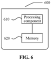
- FIG. 6 is a block diagram of a control system 600 of a beam irradiation system according to an embodiment of the present disclosure.
- the control system 600 includes a processing component 610.
- the processing component 610 further includes one or more processors, and memory resources represented by memory 620, for storing instructions executable by the processing component 610, such as applications.
- the applications stored in memory 620 may include one or more modules each corresponding to a set of instructions.
- the processing component 610 is configured to execute the instructions to perform the control methods for the beam irradiation system described above.
- the control system 600 may further include a power supply component configured to perform power management of the control system 600, a wired or wireless network interface configured to connect the control system 600 to a network, and an input/output (I/O) interface.
- the control system 600 may operate based on an operating system stored in memory 620, such as Windows ServerTM, Mac OS XTM, UnixTM, LinuxTM, FreeBSDTM, or the like.
- a non-transitory computer readable storage medium is provided.
- the storage medium enables the control system 600 to perform a control method for a beam irradiation system.
- a first control sub-module receives an instruction indicating irradiation of a first irradiation chamber, which is input by a user; the first control sub-module obtains the control right of the beam control module according to the instruction indicating irradiation of the first irradiation chamber, and when the control right of the beam control module is in the released state, the first control sub-module controls the beam generation device to emit a beam to the first irradiation chamber through the beam control module, and when the control right of the beam control module is in the state of being occupied by the second control sub-module, the first control sub-module waits for the control right of the beam control module to be released; the first control sub-module receives an instruction indicating stopping irradiation
- modules and method steps of the various examples described in connection with the embodiments disclosed herein may be implemented in electronic hardware, or a combination of computer software and electronic hardware. Whether these functions are performed in hardware or software depends on the particular application and design constraints of the solution. The skilled person may use different methods to implement the described functions for each particular application, but such implementation should not be considered to be beyond the scope of the present disclosure.
- the disclosed beam irradiation system and the control method thereof may be implemented in other ways.
- the beam irradiation system embodiment described above is merely illustrative.
- the partitioning of the module is only partitioning of logical functions, and may be implemented in another partitioning manner.
- multiple modules or components may be combined or integrated into another system, or some features may be ignored or not performed.
- the illustrated or discussed coupling or direct coupling or communication connection to each other may be through some interface, and the indirect coupling or communication connection of modules or components may be electrical, mechanical or other.
- modules illustrated as separate components may or may not be physically separate, and the components shown as modules may or may not be physical units, may be located in one location, or may be distributed across multiple network units. Some or all of the elements may be selected according to actual needs to achieve the objectives of the embodiments.
- the functions, when implemented as software functional units and sold or used as separate products, may be stored in a computer-readable storage medium.
- the technical solution of the present disclosure may essentially be embodied in the form of a software product, which is stored in a storage medium and includes instructions for causing a computer device (which may be a personal computer, a server, a network device, or the like) to perform all or part of the steps of the methods described in the various embodiments of the present disclosure.
- the storage medium includes a USB flash drive, a removable hard disk, a read-only memory (ROM), a random access memory (RAM), a magnetic disk, or an optical disk.
Landscapes
- Health & Medical Sciences (AREA)
- Engineering & Computer Science (AREA)
- Biomedical Technology (AREA)
- General Health & Medical Sciences (AREA)
- Veterinary Medicine (AREA)
- Radiology & Medical Imaging (AREA)
- Life Sciences & Earth Sciences (AREA)
- Animal Behavior & Ethology (AREA)
- Pathology (AREA)
- Public Health (AREA)
- Nuclear Medicine, Radiotherapy & Molecular Imaging (AREA)
- Physics & Mathematics (AREA)
- General Engineering & Computer Science (AREA)
- High Energy & Nuclear Physics (AREA)
- Radiation-Therapy Devices (AREA)
- Programmable Controllers (AREA)
- Heterocyclic Carbon Compounds Containing A Hetero Ring Having Nitrogen And Oxygen As The Only Ring Hetero Atoms (AREA)
Priority Applications (1)
| Application Number | Priority Date | Filing Date | Title |
|---|---|---|---|
| EP24198551.4A EP4464372A3 (fr) | 2019-11-07 | 2020-11-02 | Système d'irradiation par faisceaux et son procédé de commande |
Applications Claiming Priority (2)
| Application Number | Priority Date | Filing Date | Title |
|---|---|---|---|
| CN201911083860.5A CN112774042B (zh) | 2019-11-07 | 2019-11-07 | 射束照射系统及其控制方法 |
| PCT/CN2020/125767 WO2021088746A1 (fr) | 2019-11-07 | 2020-11-02 | Système d'irradiation par faisceaux et son procédé de commande |
Related Child Applications (2)
| Application Number | Title | Priority Date | Filing Date |
|---|---|---|---|
| EP24198551.4A Division EP4464372A3 (fr) | 2019-11-07 | 2020-11-02 | Système d'irradiation par faisceaux et son procédé de commande |
| EP24198551.4A Division-Into EP4464372A3 (fr) | 2019-11-07 | 2020-11-02 | Système d'irradiation par faisceaux et son procédé de commande |
Publications (3)
| Publication Number | Publication Date |
|---|---|
| EP4056228A1 true EP4056228A1 (fr) | 2022-09-14 |
| EP4056228A4 EP4056228A4 (fr) | 2022-12-28 |
| EP4056228B1 EP4056228B1 (fr) | 2024-12-04 |
Family
ID=75748094
Family Applications (2)
| Application Number | Title | Priority Date | Filing Date |
|---|---|---|---|
| EP20883674.2A Active EP4056228B1 (fr) | 2019-11-07 | 2020-11-02 | Système d'irradiation par faisceaux et son procédé de commande |
| EP24198551.4A Pending EP4464372A3 (fr) | 2019-11-07 | 2020-11-02 | Système d'irradiation par faisceaux et son procédé de commande |
Family Applications After (1)
| Application Number | Title | Priority Date | Filing Date |
|---|---|---|---|
| EP24198551.4A Pending EP4464372A3 (fr) | 2019-11-07 | 2020-11-02 | Système d'irradiation par faisceaux et son procédé de commande |
Country Status (10)
| Country | Link |
|---|---|
| US (1) | US12354763B2 (fr) |
| EP (2) | EP4056228B1 (fr) |
| JP (2) | JP7352025B2 (fr) |
| CN (2) | CN112774042B (fr) |
| AU (2) | AU2020378461B2 (fr) |
| CA (1) | CA3154946A1 (fr) |
| ES (1) | ES3011433T3 (fr) |
| PL (1) | PL4056228T3 (fr) |
| TW (2) | TWI813041B (fr) |
| WO (1) | WO2021088746A1 (fr) |
Cited By (1)
| Publication number | Priority date | Publication date | Assignee | Title |
|---|---|---|---|---|
| EP4183448A4 (fr) * | 2020-07-20 | 2024-05-22 | Neuboron Therapy System Ltd. | Système de radiothérapie et son procédé de commande de verrouillage de sécurité |
Families Citing this family (1)
| Publication number | Priority date | Publication date | Assignee | Title |
|---|---|---|---|---|
| JP2024547104A (ja) * | 2021-12-22 | 2024-12-26 | 中硼(厦▲門▼)医▲療▼器械有限公司 | 放射線照射システム及び載置台制御方法 |
Family Cites Families (41)
| Publication number | Priority date | Publication date | Assignee | Title |
|---|---|---|---|---|
| CN1071075A (zh) * | 1991-10-07 | 1993-04-21 | 湖南省计算技术研究所 | 中草药灸疗器 |
| JP4233854B2 (ja) * | 2002-11-28 | 2009-03-04 | 株式会社根本杏林堂 | 薬液注入装置 |
| JP4489529B2 (ja) * | 2004-07-28 | 2010-06-23 | 株式会社日立製作所 | 粒子線治療システム及び粒子線治療システムの制御システム |
| DE102005022428A1 (de) * | 2005-05-14 | 2006-11-16 | B. Braun Medizinelektronik Gmbh & Co. Kg | Verfahren und Vorrichtung zur Steuerung einer Mehrzahl von Infusionspumpen |
| DE102005044409B4 (de) * | 2005-09-16 | 2007-11-29 | Siemens Ag | Partikeltherapieanlage und Verfahren zur Ausbildung eines Strahlpfads für einen Bestrahlungsvorgang in einer Partikeltherapieanlage |
| JP4648817B2 (ja) * | 2005-10-13 | 2011-03-09 | 株式会社日立製作所 | 粒子線治療システム及びそのビームコース切替方法 |
| WO2009142546A2 (fr) * | 2008-05-22 | 2009-11-26 | Vladimir Yegorovich Balakin | Procédé et dispositif de traitement anticancéreux par particules chargées à champs multiples |
| EP2277593A1 (fr) * | 2009-07-23 | 2011-01-26 | Siemens Schweiz AG | Dispositif de pilotage d'une cible de faisceau sur une zone in-vivo |
| US10556126B2 (en) | 2010-04-16 | 2020-02-11 | Mark R. Amato | Automated radiation treatment plan development apparatus and method of use thereof |
| US8808341B2 (en) * | 2010-11-16 | 2014-08-19 | Mitsubishi Electric Corporation | Respiratory induction apparatus, respiratory induction program, and particle beam therapy system |
| WO2013146945A1 (fr) * | 2012-03-31 | 2013-10-03 | 財団法人メディポリス医学研究財団 がん粒子線治療研究センター | Dispositif utilisé pour soumettre à distance des faisceaux de particules à la technique des feux croisés |
| US11253732B2 (en) * | 2012-08-22 | 2022-02-22 | Energize Medical Llc | Therapeutic energy systems |
| JP5996456B2 (ja) * | 2013-02-27 | 2016-09-21 | 住友重機械工業株式会社 | 中性子捕捉療法システム |
| CN105120951B (zh) * | 2013-04-19 | 2017-09-26 | 三菱电机株式会社 | 粒子射线治疗系统 |
| CN103301009B (zh) * | 2013-06-18 | 2015-08-19 | 洛阳理工学院 | 人体背部自动控制刮痧仪 |
| CN203447468U (zh) * | 2013-08-29 | 2014-02-26 | 东莞市骏炜电器有限公司 | 一种光电理疗床控制装置 |
| JP6109702B2 (ja) * | 2013-10-15 | 2017-04-05 | 住友重機械工業株式会社 | 荷電粒子線照射装置 |
| JP6009691B2 (ja) * | 2013-11-21 | 2016-10-19 | 三菱電機株式会社 | 粒子線治療装置 |
| JP6220713B2 (ja) * | 2014-03-27 | 2017-10-25 | 株式会社日立製作所 | 荷電粒子ビーム照射システム |
| US9640449B2 (en) * | 2014-04-21 | 2017-05-02 | Kla-Tencor Corporation | Automated inline inspection of wafer edge strain profiles using rapid photoreflectance spectroscopy |
| CN104490409A (zh) * | 2014-10-22 | 2015-04-08 | 珠海和佳医疗设备股份有限公司 | 一种u形臂x线机的控制装置 |
| JP6427069B2 (ja) * | 2015-05-27 | 2018-11-21 | 株式会社日立製作所 | 粒子線治療システム |
| CN205127175U (zh) * | 2015-11-06 | 2016-04-06 | 柳忠锋 | 高能聚焦超声肿瘤治疗累积热损伤自动保护避让系统 |
| CN105719982A (zh) * | 2016-02-05 | 2016-06-29 | 东方晶源微电子科技(北京)有限公司 | 多工作台或多腔体检测系统 |
| GB2547451B (en) * | 2016-02-18 | 2019-06-26 | Elekta ltd | Device identification |
| WO2018006550A1 (fr) | 2016-07-04 | 2018-01-11 | 南京中硼联康医疗科技有限公司 | Dispositif de traitement par neutrons |
| JP2018041790A (ja) * | 2016-09-06 | 2018-03-15 | 株式会社アドバンテスト | 露光装置および露光データ構造 |
| JP6719344B2 (ja) * | 2016-09-08 | 2020-07-08 | 株式会社日立製作所 | 粒子線治療システム及びシステム導入手法 |
| JP2019535102A (ja) * | 2016-10-05 | 2019-12-05 | エーエスエムエル ネザーランズ ビー.ブイ. | 電子ビーム伝送システム |
| JP2018078250A (ja) * | 2016-11-11 | 2018-05-17 | 株式会社ニューフレアテクノロジー | マルチ荷電粒子ビーム描画装置 |
| TWI640291B (zh) * | 2016-12-16 | 2018-11-11 | 巽晨國際股份有限公司 | Electromagnetic wave treatment device and method of use thereof |
| CN107049359A (zh) * | 2017-01-23 | 2017-08-18 | 杨霜 | 一种智能超声波产生装置 |
| CN206664795U (zh) * | 2017-03-01 | 2017-11-24 | 深圳市亮点智控科技有限公司 | 姿态车 |
| WO2018167924A1 (fr) * | 2017-03-16 | 2018-09-20 | 株式会社ニコン | Système optique à faisceau de particules chargées, appareil d'exposition, procédé d'exposition et procédé de fabrication de dispositif |
| CN109464750B (zh) * | 2017-09-07 | 2024-01-12 | 南京中硼联康医疗科技有限公司 | 中子捕获治疗系统 |
| CN107845211A (zh) * | 2017-10-31 | 2018-03-27 | 无锡七百二十度科技有限公司 | 一种自助图书馆及其服务方法 |
| CN108287519B (zh) * | 2018-02-05 | 2019-08-23 | 合肥中科离子医学技术装备有限公司 | 用于质子治疗设备安全联锁的逻辑结构和实现方法 |
| CN108379750B (zh) * | 2018-04-13 | 2021-05-25 | 深圳市奥沃医学新技术发展有限公司 | 联锁控制方法、装置、系统及放射治疗设备 |
| BR112020021584A2 (pt) * | 2018-04-25 | 2021-01-19 | Adam S.A. | Um sistema acelerador linear de prótons para irradiar tecidos com duas ou mais fontes de rf |
| CN209451161U (zh) * | 2018-05-18 | 2019-10-01 | 中硼(厦门)医疗器械有限公司 | 中子捕获治疗系统及载置台 |
| CN110159442B (zh) * | 2019-05-09 | 2022-07-22 | 重庆潍柴发动机有限公司 | 一种控制方法、控制装置及控制系统 |
-
2019
- 2019-11-07 CN CN201911083860.5A patent/CN112774042B/zh active Active
- 2019-11-07 CN CN202311051288.0A patent/CN116999722A/zh active Pending
-
2020
- 2020-11-02 AU AU2020378461A patent/AU2020378461B2/en active Active
- 2020-11-02 CA CA3154946A patent/CA3154946A1/fr active Pending
- 2020-11-02 EP EP20883674.2A patent/EP4056228B1/fr active Active
- 2020-11-02 ES ES20883674T patent/ES3011433T3/es active Active
- 2020-11-02 PL PL20883674.2T patent/PL4056228T3/pl unknown
- 2020-11-02 EP EP24198551.4A patent/EP4464372A3/fr active Pending
- 2020-11-02 WO PCT/CN2020/125767 patent/WO2021088746A1/fr not_active Ceased
- 2020-11-02 JP JP2022526231A patent/JP7352025B2/ja active Active
- 2020-11-05 TW TW110138461A patent/TWI813041B/zh active
- 2020-11-05 TW TW109138714A patent/TWI747598B/zh active
-
2022
- 2022-05-02 US US17/734,190 patent/US12354763B2/en active Active
-
2023
- 2023-09-14 JP JP2023148855A patent/JP7635325B2/ja active Active
-
2024
- 2024-05-17 AU AU2024203296A patent/AU2024203296B2/en active Active
Cited By (1)
| Publication number | Priority date | Publication date | Assignee | Title |
|---|---|---|---|---|
| EP4183448A4 (fr) * | 2020-07-20 | 2024-05-22 | Neuboron Therapy System Ltd. | Système de radiothérapie et son procédé de commande de verrouillage de sécurité |
Also Published As
| Publication number | Publication date |
|---|---|
| JP2024001027A (ja) | 2024-01-09 |
| US12354763B2 (en) | 2025-07-08 |
| CA3154946A1 (fr) | 2021-05-14 |
| TW202119457A (zh) | 2021-05-16 |
| WO2021088746A1 (fr) | 2021-05-14 |
| JP7635325B2 (ja) | 2025-02-25 |
| TW202207266A (zh) | 2022-02-16 |
| EP4056228A4 (fr) | 2022-12-28 |
| TWI747598B (zh) | 2021-11-21 |
| EP4464372A3 (fr) | 2025-01-15 |
| US20220262536A1 (en) | 2022-08-18 |
| ES3011433T3 (en) | 2025-04-07 |
| AU2024203296A1 (en) | 2024-06-06 |
| EP4056228B1 (fr) | 2024-12-04 |
| TWI813041B (zh) | 2023-08-21 |
| AU2020378461A1 (en) | 2022-05-26 |
| PL4056228T3 (pl) | 2025-04-14 |
| AU2020378461B2 (en) | 2024-02-22 |
| AU2024203296B2 (en) | 2026-02-12 |
| CN112774042A (zh) | 2021-05-11 |
| EP4464372A2 (fr) | 2024-11-20 |
| CN112774042B (zh) | 2023-09-01 |
| JP2023501412A (ja) | 2023-01-18 |
| JP7352025B2 (ja) | 2023-09-27 |
| CN116999722A (zh) | 2023-11-07 |
Similar Documents
| Publication | Publication Date | Title |
|---|---|---|
| AU2024203296B2 (en) | Beam irradiation system and control method therefor | |
| EP3048691B1 (fr) | Système et procédé de surveillance de coordination/de commande de chargeur intégré multi-sorties pour automobile électrique | |
| US9456799B2 (en) | Modality with multicomputer system and powering sequence therefor | |
| TWI810611B (zh) | 放射治療系統及其安全聯鎖控制方法 | |
| CN113952635B (zh) | 放射治疗系统及其安全联锁控制方法 | |
| EP4183448A1 (fr) | Système de radiothérapie et son procédé de commande de verrouillage de sécurité | |
| RU2796908C1 (ru) | Система облучения пучком и способ управления ею | |
| WO2021000298A1 (fr) | Défibrillateur et serveur de gestion | |
| EP2902045A1 (fr) | Dispositif médical et procédé pour le commander | |
| CN117713361A (zh) | 电网监控系统、电子设备及计算机可读存储介质 | |
| Luchetta et al. | Fast control and data acquisition in the neutral beam test facility | |
| He et al. | Implementation and design of the control system for poloidal field power supply | |
| CN110827523B (zh) | 半导体设备报警管理系统 | |
| US20170078450A1 (en) | Remote power management | |
| Benincasa et al. | Design goals and application software layout for the CERN 28 GeV accelerator complex | |
| Kaportsev et al. | The Program Tools for KSRS Operation | |
| US20250256129A1 (en) | Method and apparatus for controlling radiotherapy equipment, device, and storage medium | |
| CN104699528B (zh) | 基于NetWeaver的排程方法 | |
| Shi et al. | Design of Distributed Control System for Radiotherapy Equipment Based on Field Bus | |
| US20160171868A1 (en) | Cartridge interdependence switch |
Legal Events
| Date | Code | Title | Description |
|---|---|---|---|
| STAA | Information on the status of an ep patent application or granted ep patent |
Free format text: STATUS: UNKNOWN |
|
| STAA | Information on the status of an ep patent application or granted ep patent |
Free format text: STATUS: THE INTERNATIONAL PUBLICATION HAS BEEN MADE |
|
| PUAI | Public reference made under article 153(3) epc to a published international application that has entered the european phase |
Free format text: ORIGINAL CODE: 0009012 |
|
| STAA | Information on the status of an ep patent application or granted ep patent |
Free format text: STATUS: REQUEST FOR EXAMINATION WAS MADE |
|
| 17P | Request for examination filed |
Effective date: 20210512 |
|
| AK | Designated contracting states |
Kind code of ref document: A1 Designated state(s): AL AT BE BG CH CY CZ DE DK EE ES FI FR GB GR HR HU IE IS IT LI LT LU LV MC MK MT NL NO PL PT RO RS SE SI SK SM TR |
|
| A4 | Supplementary search report drawn up and despatched |
Effective date: 20221128 |
|
| RIC1 | Information provided on ipc code assigned before grant |
Ipc: A61N 5/10 20060101AFI20221122BHEP |
|
| DAV | Request for validation of the european patent (deleted) | ||
| DAX | Request for extension of the european patent (deleted) | ||
| GRAP | Despatch of communication of intention to grant a patent |
Free format text: ORIGINAL CODE: EPIDOSNIGR1 |
|
| STAA | Information on the status of an ep patent application or granted ep patent |
Free format text: STATUS: GRANT OF PATENT IS INTENDED |
|
| INTG | Intention to grant announced |
Effective date: 20240808 |
|
| GRAS | Grant fee paid |
Free format text: ORIGINAL CODE: EPIDOSNIGR3 |
|
| GRAA | (expected) grant |
Free format text: ORIGINAL CODE: 0009210 |
|
| STAA | Information on the status of an ep patent application or granted ep patent |
Free format text: STATUS: THE PATENT HAS BEEN GRANTED |
|
| AK | Designated contracting states |
Kind code of ref document: B1 Designated state(s): AL AT BE BG CH CY CZ DE DK EE ES FI FR GB GR HR HU IE IS IT LI LT LU LV MC MK MT NL NO PL PT RO RS SE SI SK SM TR |
|
| REG | Reference to a national code |
Ref country code: CH Ref legal event code: EP |
|
| REG | Reference to a national code |
Ref country code: DE Ref legal event code: R096 Ref document number: 602020042762 Country of ref document: DE |
|
| REG | Reference to a national code |
Ref country code: IE Ref legal event code: FG4D |
|
| REG | Reference to a national code |
Ref country code: LT Ref legal event code: MG9D |
|
| REG | Reference to a national code |
Ref country code: ES Ref legal event code: FG2A Ref document number: 3011433 Country of ref document: ES Kind code of ref document: T3 Effective date: 20250407 |
|
| REG | Reference to a national code |
Ref country code: NL Ref legal event code: MP Effective date: 20241204 |
|
| PG25 | Lapsed in a contracting state [announced via postgrant information from national office to epo] |
Ref country code: HR Free format text: LAPSE BECAUSE OF FAILURE TO SUBMIT A TRANSLATION OF THE DESCRIPTION OR TO PAY THE FEE WITHIN THE PRESCRIBED TIME-LIMIT Effective date: 20241204 |
|
| PG25 | Lapsed in a contracting state [announced via postgrant information from national office to epo] |
Ref country code: FI Free format text: LAPSE BECAUSE OF FAILURE TO SUBMIT A TRANSLATION OF THE DESCRIPTION OR TO PAY THE FEE WITHIN THE PRESCRIBED TIME-LIMIT Effective date: 20241204 |
|
| PG25 | Lapsed in a contracting state [announced via postgrant information from national office to epo] |
Ref country code: BG Free format text: LAPSE BECAUSE OF FAILURE TO SUBMIT A TRANSLATION OF THE DESCRIPTION OR TO PAY THE FEE WITHIN THE PRESCRIBED TIME-LIMIT Effective date: 20241204 |
|
| PG25 | Lapsed in a contracting state [announced via postgrant information from national office to epo] |
Ref country code: NO Free format text: LAPSE BECAUSE OF FAILURE TO SUBMIT A TRANSLATION OF THE DESCRIPTION OR TO PAY THE FEE WITHIN THE PRESCRIBED TIME-LIMIT Effective date: 20250304 |
|
| PG25 | Lapsed in a contracting state [announced via postgrant information from national office to epo] |
Ref country code: GR Free format text: LAPSE BECAUSE OF FAILURE TO SUBMIT A TRANSLATION OF THE DESCRIPTION OR TO PAY THE FEE WITHIN THE PRESCRIBED TIME-LIMIT Effective date: 20250305 Ref country code: LV Free format text: LAPSE BECAUSE OF FAILURE TO SUBMIT A TRANSLATION OF THE DESCRIPTION OR TO PAY THE FEE WITHIN THE PRESCRIBED TIME-LIMIT Effective date: 20241204 |
|
| PG25 | Lapsed in a contracting state [announced via postgrant information from national office to epo] |
Ref country code: RS Free format text: LAPSE BECAUSE OF FAILURE TO SUBMIT A TRANSLATION OF THE DESCRIPTION OR TO PAY THE FEE WITHIN THE PRESCRIBED TIME-LIMIT Effective date: 20250304 |
|
| PG25 | Lapsed in a contracting state [announced via postgrant information from national office to epo] |
Ref country code: NL Free format text: LAPSE BECAUSE OF FAILURE TO SUBMIT A TRANSLATION OF THE DESCRIPTION OR TO PAY THE FEE WITHIN THE PRESCRIBED TIME-LIMIT Effective date: 20241204 |
|
| REG | Reference to a national code |
Ref country code: AT Ref legal event code: MK05 Ref document number: 1747527 Country of ref document: AT Kind code of ref document: T Effective date: 20241204 |
|
| PG25 | Lapsed in a contracting state [announced via postgrant information from national office to epo] |
Ref country code: SM Free format text: LAPSE BECAUSE OF FAILURE TO SUBMIT A TRANSLATION OF THE DESCRIPTION OR TO PAY THE FEE WITHIN THE PRESCRIBED TIME-LIMIT Effective date: 20241204 |
|
| PG25 | Lapsed in a contracting state [announced via postgrant information from national office to epo] |
Ref country code: IS Free format text: LAPSE BECAUSE OF FAILURE TO SUBMIT A TRANSLATION OF THE DESCRIPTION OR TO PAY THE FEE WITHIN THE PRESCRIBED TIME-LIMIT Effective date: 20250404 |
|
| PG25 | Lapsed in a contracting state [announced via postgrant information from national office to epo] |
Ref country code: PT Free format text: LAPSE BECAUSE OF FAILURE TO SUBMIT A TRANSLATION OF THE DESCRIPTION OR TO PAY THE FEE WITHIN THE PRESCRIBED TIME-LIMIT Effective date: 20250404 |
|
| PG25 | Lapsed in a contracting state [announced via postgrant information from national office to epo] |
Ref country code: EE Free format text: LAPSE BECAUSE OF FAILURE TO SUBMIT A TRANSLATION OF THE DESCRIPTION OR TO PAY THE FEE WITHIN THE PRESCRIBED TIME-LIMIT Effective date: 20241204 |
|
| PG25 | Lapsed in a contracting state [announced via postgrant information from national office to epo] |
Ref country code: AT Free format text: LAPSE BECAUSE OF FAILURE TO SUBMIT A TRANSLATION OF THE DESCRIPTION OR TO PAY THE FEE WITHIN THE PRESCRIBED TIME-LIMIT Effective date: 20241204 Ref country code: RO Free format text: LAPSE BECAUSE OF FAILURE TO SUBMIT A TRANSLATION OF THE DESCRIPTION OR TO PAY THE FEE WITHIN THE PRESCRIBED TIME-LIMIT Effective date: 20241204 |
|
| PG25 | Lapsed in a contracting state [announced via postgrant information from national office to epo] |
Ref country code: SK Free format text: LAPSE BECAUSE OF FAILURE TO SUBMIT A TRANSLATION OF THE DESCRIPTION OR TO PAY THE FEE WITHIN THE PRESCRIBED TIME-LIMIT Effective date: 20241204 |
|
| PG25 | Lapsed in a contracting state [announced via postgrant information from national office to epo] |
Ref country code: CZ Free format text: LAPSE BECAUSE OF FAILURE TO SUBMIT A TRANSLATION OF THE DESCRIPTION OR TO PAY THE FEE WITHIN THE PRESCRIBED TIME-LIMIT Effective date: 20241204 |
|
| REG | Reference to a national code |
Ref country code: DE Ref legal event code: R097 Ref document number: 602020042762 Country of ref document: DE |
|
| PG25 | Lapsed in a contracting state [announced via postgrant information from national office to epo] |
Ref country code: SE Free format text: LAPSE BECAUSE OF FAILURE TO SUBMIT A TRANSLATION OF THE DESCRIPTION OR TO PAY THE FEE WITHIN THE PRESCRIBED TIME-LIMIT Effective date: 20241204 |
|
| PG25 | Lapsed in a contracting state [announced via postgrant information from national office to epo] |
Ref country code: DK Free format text: LAPSE BECAUSE OF FAILURE TO SUBMIT A TRANSLATION OF THE DESCRIPTION OR TO PAY THE FEE WITHIN THE PRESCRIBED TIME-LIMIT Effective date: 20241204 |
|
| PLBE | No opposition filed within time limit |
Free format text: ORIGINAL CODE: 0009261 |
|
| STAA | Information on the status of an ep patent application or granted ep patent |
Free format text: STATUS: NO OPPOSITION FILED WITHIN TIME LIMIT |
|
| 26N | No opposition filed |
Effective date: 20250905 |
|
| PGFP | Annual fee paid to national office [announced via postgrant information from national office to epo] |
Ref country code: DE Payment date: 20251118 Year of fee payment: 6 |
|
| PGFP | Annual fee paid to national office [announced via postgrant information from national office to epo] |
Ref country code: GB Payment date: 20251111 Year of fee payment: 6 |
|
| PGFP | Annual fee paid to national office [announced via postgrant information from national office to epo] |
Ref country code: IT Payment date: 20251128 Year of fee payment: 6 |
|
| PGFP | Annual fee paid to national office [announced via postgrant information from national office to epo] |
Ref country code: FR Payment date: 20251110 Year of fee payment: 6 |
|
| PGFP | Annual fee paid to national office [announced via postgrant information from national office to epo] |
Ref country code: PL Payment date: 20251016 Year of fee payment: 6 |
|
| PGFP | Annual fee paid to national office [announced via postgrant information from national office to epo] |
Ref country code: ES Payment date: 20251216 Year of fee payment: 6 |