EP4056376B1 - Imprimante à jet d'encre et procédé d'entretien de son filtre - Google Patents
Imprimante à jet d'encre et procédé d'entretien de son filtre Download PDFInfo
- Publication number
- EP4056376B1 EP4056376B1 EP22160511.6A EP22160511A EP4056376B1 EP 4056376 B1 EP4056376 B1 EP 4056376B1 EP 22160511 A EP22160511 A EP 22160511A EP 4056376 B1 EP4056376 B1 EP 4056376B1
- Authority
- EP
- European Patent Office
- Prior art keywords
- ink
- filter
- pump
- supply pipe
- time
- Prior art date
- Legal status (The legal status is an assumption and is not a legal conclusion. Google has not performed a legal analysis and makes no representation as to the accuracy of the status listed.)
- Active
Links
Images


Classifications
-
- B—PERFORMING OPERATIONS; TRANSPORTING
- B41—PRINTING; LINING MACHINES; TYPEWRITERS; STAMPS
- B41J—TYPEWRITERS; SELECTIVE PRINTING MECHANISMS, i.e. MECHANISMS PRINTING OTHERWISE THAN FROM A FORME; CORRECTION OF TYPOGRAPHICAL ERRORS
- B41J2/00—Typewriters or selective printing mechanisms characterised by the printing or marking process for which they are designed
- B41J2/005—Typewriters or selective printing mechanisms characterised by the printing or marking process for which they are designed characterised by bringing liquid or particles selectively into contact with a printing material
- B41J2/01—Ink jet
- B41J2/17—Ink jet characterised by ink handling
- B41J2/175—Ink supply systems ; Circuit parts therefor
- B41J2/17563—Ink filters
-
- B—PERFORMING OPERATIONS; TRANSPORTING
- B41—PRINTING; LINING MACHINES; TYPEWRITERS; STAMPS
- B41J—TYPEWRITERS; SELECTIVE PRINTING MECHANISMS, i.e. MECHANISMS PRINTING OTHERWISE THAN FROM A FORME; CORRECTION OF TYPOGRAPHICAL ERRORS
- B41J2/00—Typewriters or selective printing mechanisms characterised by the printing or marking process for which they are designed
- B41J2/005—Typewriters or selective printing mechanisms characterised by the printing or marking process for which they are designed characterised by bringing liquid or particles selectively into contact with a printing material
- B41J2/01—Ink jet
- B41J2/17—Ink jet characterised by ink handling
- B41J2/175—Ink supply systems ; Circuit parts therefor
- B41J2/17596—Ink pumps, ink valves
-
- B—PERFORMING OPERATIONS; TRANSPORTING
- B41—PRINTING; LINING MACHINES; TYPEWRITERS; STAMPS
- B41J—TYPEWRITERS; SELECTIVE PRINTING MECHANISMS, i.e. MECHANISMS PRINTING OTHERWISE THAN FROM A FORME; CORRECTION OF TYPOGRAPHICAL ERRORS
- B41J2/00—Typewriters or selective printing mechanisms characterised by the printing or marking process for which they are designed
- B41J2/005—Typewriters or selective printing mechanisms characterised by the printing or marking process for which they are designed characterised by bringing liquid or particles selectively into contact with a printing material
- B41J2/01—Ink jet
- B41J2/17—Ink jet characterised by ink handling
- B41J2/18—Ink recirculation systems
Definitions
- This invention relates to an inkjet printing apparatus for performing printing by dispensing ink to a printing medium, and a method of maintaining a filter thereof.
- this type of apparatus includes a main tank, a pump, a filter, a subtank, a head, and a supply pipe. See Japanese Unexamined Patent Publication No. 2019-195967 , for example.
- the main tank stores ink for forming images.
- the supply pipe communicatively connects the main tank and the head, and has the pump, filter, and subtank arranged thereon in this order.
- the pump supplies the ink from the main tank to the subtank through the filter.
- the subtank supplies the ink to the head.
- the filter removes, for example, particles having mixed in at times of ink replenishing operation for the main tank, and particles having generated from connecting locations or movable parts of the supply pipe, such particles not contributing to image formation, but causing choking of the head.
- the ink used in the inkjet printing apparatus if it is UV ink which is dried by UV light, is composed of dispersed ingredients such as pigment, dispersant, and monomer. If it is water pigment ink which is dried by heat, it is composed of ingredients such as pigment, dispersant, stabilizer, and water.
- the filter captures, for example, loosely flocculated masses particularly of the pigment and monomer among these ingredients, and these masses can block the particles which should intrinsically be removed. This poses a problem that the high filter changing frequency raises operation cost.
- US 2005/018003 A1 discloses an inkjet recording device comprising an ink chamber that contains ink, a nozzle communicating with the ink chamber, which ejects the ink from the ink chamber, and a filter being disposed in a tube connecting the ink chamber and the nozzle at an end portion of the tube being connected to the ink chamber.
- This invention has been made having regard to the state of the art noted above, and its object is to provide an inkjet printing apparatus and a method of maintaining a filter thereof which can reduce operation cost due to changing of the filter by improving blocking of the filter.
- An inkjet printing apparatus performs printing on a printing medium by feeding ink to an inkjet head having a plurality of nozzles and dispensing the ink from the inkjet head to the printing medium.
- the apparatus comprises a tank for storing the ink; a supply pipe communicatively connecting the tank and the inkjet head; a pump mounted on the supply pipe for feeding the ink stored in the tank to the inkjet head; a filter disposed on a path of the supply pipe; and a controller for operating the pump and controlling feeding of the ink; wherein the controller is configured to operate the pump to engage in forward drive for feeding the ink from the tank toward the inkjet head in time of printing operation that causes the inkjet head to dispense the ink fed from the tank, and to operate the pump to engage in backward drive for feeding the ink from a position downstream of the pump back to the tank in time of functional recovery operation for improving choking of the filter.
- the controller provides the forward drive of the pump for feeding the ink from the tank toward the inkjet head in time of printing operation.
- the controller provides the backward drive of the pump for feeding the ink from a position downstream of the pump back to the tank in time of functional recovery operation.
- This can re-disperse, in the ink within the supply pipe, masses of ingredients of the ink captured by the filter during the printing operation.
- the choking of the filter can thereby be improved, which can reduce operation cost due to changing of the filter.
- the filter can be used to the best advantage for its intrinsic purpose of removing particles that do not contribute to image formation, but cause choking of the inkjet head.
- the apparatus further comprises a degassing filter mounted on the supply pipe between the pump and the inkjet head and downstream of the filter for removing bubbles from the ink; wherein the controller is configured to operate the pump to engage in the backward drive, in time of functional recovery operation, until an interface between the ink and gas in a portion of the supply pipe adjacent the inkjet head is located on a side of the degassing filter adjacent the inkjet head.
- the controller in time of functional recovery operation, provides the backward drive until the interface between the ink and gas in the portion of the supply pipe adjacent the inkjet head is located on the side of the degassing filter adjacent the inkjet head. Consequently, the interface between the ink and gas is not located in the degassing filter.
- the degassing filter can therefore remain filled with the ink during the functional recovery operation. This prevents the bubbles mixing into the ink.
- the controller is configured to repeat the forward drive and the backward drive a plurality of times in time of functional recovery operation.
- the controller in time of functional recovery operation, repeats the forward drive and backward drive two or more times. Consequently, the ink in the supply pipe can fully be agitated through the filter. The masses of the ingredients of the ink captured by the filter can therefore be re-dispersed reliably.
- the controller is configured to provide the backward drive based on a relationship between a still time which is a duration of a state where the ink is not flowing, and an ink backflow amount necessary for re-dispersing ingredients captured by the filter.
- the necessary ink backflow amount is determined from the still time. Since the functional recovery operation can be carried out with a minimum backflow amount, the functional recovery operation can be performed efficiently.
- the apparatus further comprises liquid level sensors disposed in two locations on the supply pipe adjacent the inkjet head and adjacent the pump; wherein the controller is configured to perform the backward drive in time of functional recovery operation in order to allow the gas-liquid interface of the ink in the supply pipe to settle between the liquid level sensors in the two locations.
- the controller In time of functional recovery operation, the controller provides the backward drive so that the gas-liquid interface of the ink in the supply pipe may settle between the liquid level sensors in the two locations. Consequently, there is no possibility of bubbles mixing in the ink or the backward drive being done to excess. Thus, the functional recovery operation can be carried out reliably.
- the pump is a tube pump including an elastic tube with one end thereof connected to an upstream portion of the supply pipe, and the other end connected through a U-shaped portion to a downstream portion of the supply pipe, a plurality of rollers for pressing an inner circumference side of the tube from a center of the U-shaped portion to an outer circumferential side, and a rotating element for rotating the plurality of rollers.
- the pump engaging in the backward drive causes ingredients of the film captured by the filter to re-disperse in the ink stored in the supply pipe to be used in the printing.
- a method of maintaining a filter of an inkjet printing apparatus which performs printing on a printing medium by feeding ink with a pump from an ink tank to an inkjet head through the filter, and dispensing the ink from the inkjet head to the printing medium, comprises the following step: a functional recovery operation step for operating the pump to engage in backward drive for feeding the ink from downstream of the pump backward through the filter to the tank, to re-disperse ingredients of the ink captured in an upstream portion of the filter for use in the printing and for improving choking of the filter.
- the functional recovery operation step operates the pump to engage in backward drive, thereby re-dispersing the ingredients of the ink captured in the upstream portion of the filter for use in printing, and for improving the choking of the filter.
- This can reduce operation cost due to changing of the filter.
- the filter can be used to the best advantage for its intrinsic purpose of removing particles that do not contribute to image formation, but cause choking of the head.
- the ingredients of the ink are re-dispersed in the ink within the supply pipe, property changes of the ink can be suppressed. As a result, there occurs no adverse influence due to the property changes of the ink, whereby the same quality in printing can be maintained over a long period of time.
- Fig. 1 is a schematic overall view of an inkjet printing system according to Embodiment 1.
- the inkjet printing system includes a sheet feeder 1, an inkjet printing apparatus 3, and a takeup roller 5.
- the sheet feeder 1 holds web paper WP in a roll form to be rotatable about a horizontal axis.
- the sheet feeder 1 unwinds the web paper WP and feeds it to the inkjet printing apparatus 3.
- the inkjet printing apparatus 3 prints images by dispensing ink to the web paper WP, and feeds the web paper WP to the takeup roller 5.
- the takeup roller 5 winds on a horizontal axis the web paper WP printed in the inkjet printing apparatus 3.
- transport direction X the direction in which the web paper WP is fed by the sheet feeder 1 and transported.
- a horizontal direction perpendicular to the transport direction X is regarded as width direction Y.
- the above sheet feeder 1 is located upstream of the inkjet printing apparatus 3 in the transport direction X.
- the above takeup roller 5 is located downstream of the inkjet printing apparatus 3 in the transport direction X.
- the inkjet printing apparatus 3 includes a drive roller 7 disposed in an upstream position for taking in the web paper WP from the sheet feeder 1.
- the web paper WP unwound from the sheet feeder 1 by the drive roller 7 is fed in the transport direction X and transported toward the takeup roller 5 by a plurality of transport rollers 9.
- a drive roller 11 is disposed between the most downstream transport roller 9 and the takeup roller 5. This drive roller 11 feeds the web paper WP transported on the transport rollers 9 forward toward the takeup roller 5.
- the inkjet printing apparatus 3 includes, between the drive roller 7 and drive roller 11, a printing unit 13, a drying section 15, and an inspecting device 17 arranged in the stated order from upstream.
- the printing unit 13 performs printing on the web paper WP.
- the drying section 15 dries the web paper WP printed by the printing unit 13.
- the drying section 15 includes a UV lamp or UV-LED.
- the drying section 15 includes a heat roller and/or a hot air machine.
- the inspecting device 17 checks whether portions printed on the web paper WP have stains, omissions or other defects.
- the printing unit 13 includes an inkjet head 19 having a plurality of nozzles for dispensing the ink to the web paper WP.
- a plurality of inkjet heads 19 are arranged along the transport direction X of the web paper WP.
- four printing units 13 are provided for black (K), cyan (C), magenta (M), and yellow (Y). In the following description, however, a construction having only one printing unit 13 will be taken for example.
- the printing unit 13 has a length in the width direction Y of the web paper WP that exceeds the width of the web paper WP.
- the printing unit 13 has the inkjet head 19 that can print on a printing area in the width direction of the web paper WP without moving in the width direction Y.
- the inkjet head 19 is supplied with the ink through a subtank 21 from an ink feeder 23.
- the inkjet printing apparatus 3 includes a controller 25 for performing overall control of the drive rollers 7 and 11, printing unit 13, drying section 15, inspecting device 17, and ink feeder 23.
- the controller 25 has, directly or indirectly connected thereto, a counter 27, a storage unit 29, and a computing unit 31.
- the controller 25 is constructed of a CPU and memory, for example.
- the counter 27 measures, for example, time when the inkjet printing apparatus 3 suspends a printing process.
- the storage unit 29 stores a relationship between still time and backflow amount which will be describe in detail hereinafter.
- the computing unit 31, based on the time measured by the counter 27 and the relationship between still time and backflow amount, performs mathematical operations for determining an operating time of backward drive for operating the ink feeder 23.
- the above web paper WP corresponds to the "printing medium" in this invention.
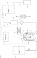
- Fig. 2 is a block diagram of the ink feeder 23 in the inkjet printing system according to Embodiment 1.
- the ink feeder 23 includes a main tank 33, a switch valve 35, a supply pipe 37, a pump 39, a filter 41, a degassing filter 43, and a liquid feed amount detector 45.
- the main tank 33 is a receptacle that stores ink.
- the operator of this apparatus replenishes the main tank 33 with ink at appropriate times.
- the switch valve 35 opens and closes under control of the controller 25.
- the switch valve 35 permits or blocks circulation of the ink through the supply pipe 37.
- the supply pipe 37 communicatively connects the main tank 33 and inkjet head 19.
- the supply pipe 37 serves as passage of the ink.
- the pump 39 feeds under pressure the ink present in the main tank 33 and supply pipe 37.
- This pump 39 preferably is a tube pump (also called a roller pump, peristaltic pump, and tubing pump).
- the pump 39 has an inlet 47, an outlet 49, a tube 51, a rotating element 53, a housing 55, and a motor 57.
- the inlet 47 and outlet 49 are connected to the supply pipe 37 for communication therewith.
- the inlet 47 and outlet 49 are connected to opposite ends of the tube 51.
- the inlet 47 is connected to an upstream portion of the supply pipe 37 as seen in time of normal ink feeding operation of the pump 39.
- the time of normal ink feeding operation is a time of printing operation, for example, and it refers to an operation for feeding the ink from the main tank 33 toward the inkjet head 19.
- the outlet 49 is connected to a downstream portion of the supply pipe 37 as seen in time of normal ink feeding operation of the pump 39.
- the tube 51 is made into a U-shape and connects the inlet 47 and outlet 49.
- the tube 51 is formed of an elastic body. Therefore, when the tube 51 is pressed from outside, its flow passage cross-section area will be reduced. When the pressure is removed, it will return to a usual flow passage cross-section area.
- the tube 51 has the rotating element 53 located centrally of the U-shape.
- the tube 51 is fitted in the housing 55 so that its U-shaped outer circumferential surface may extend along and in contact with an inner circumferential surface of the housing 55.
- the rotating element 53 has a cross-shaped rotating frame 59 and a plurality of rollers 60. Each roller 60 is rotatably attached to one distal end of the rotating frame 59.
- the rotating element 53 rotates with each roller 60 pressing on the inner circumferential surface of the tube 51 toward the outer circumferential surface, thereby squeezing and diminishing the flow passage cross-section area of the tube 51.
- This rotating operation in one direction of the rotating element 53 feeds the ink in the tube 51 from the inlet 47 to the outlet 49.
- a rotating operation in the other direction of the rotating element 53 feeds the ink in the tube 51 from the outlet 49 to the inlet 47.
- the rotating element 53 is driven to rotate by the motor 57.
- the motor 57 has its direction of rotation and rotating speed controlled by the controller 25.
- the above pump 39 is capable of continuous liquid feeding, and is therefore suitable for feeding a large amount of ink.
- the rotational frequency of the rotating element 53 and the flow rate are basically proportional.
- the flow rate will also become constant. This provides an advantage of facilitating a fixed quantity liquid delivery.
- the filter 41 is mounted on a portion of the supply pipe 37 downstream of the pump 39 as seen in time of normal ink feeding operation.
- the filter 41 is provided for removing particles mixed into the ink which do not contribute to image formation but can cause choking of the inkjet head 19. However, this filter 41 will capture part of the ingredients of the ink included in the main tank 33.
- the ink is composed of ingredients such as pigment, dispersant, stabilizer, and so on, which are present in a dispersed state. Particularly pigment and monomer among these ingredients can be loosely flocculated in the ink. Then, the pigment and monomer will form larger flocculated masses than when in the dispersed state.
- the filter 4 may capture the flocculated masses of the ink ingredients rather than the particles which should intrinsically be removed, and get blocked by these masses together with the particles.
- the filter 41 is attached to the supply pipe 37 in a position for allowing the ink to flow upward from below during the normal ink feeding operation. Consequently, at a time of backward drive which will be described hereinafter, the filter 41 will easily release the captured masses, with gravity also acting on the masses.
- the degassing filter 43 is mounted on a portion of the supply pipe 37 downstream of the filter 41 as seen in time of normal ink feeding operation.
- the degassing filter 43 removes bubbles included in the ink flowing through the supply pipe 37.
- bubbles are included in the ink, there is a possibility of a fault that the ink is not dispensed appropriately from the inkjet head 19. Since this degassing filter 43 removes even bubbles included in the ink, printing is performed with high quality.
- the subtank 21 is mounted on a portion of the supply pipe 37 downstream of the degassing filter 43 as seen in time of normal ink feeding operation.
- the subtank 21 has a level sensor (not shown) installed therein. When the amount of ink in the subtank 21 falls below a fixed value as a result of consumption of the ink at the inkjet head 19, the controller 25 will detect this and supply the ink from the main tank 33 to bring the amount of ink in the subtank 21 back to the fixed value.
- the liquid feed amount detector 45 is disposed between the filter 41 and degassing filter 43. This liquid feed amount detector 45 detects the amount of ink that flows through the supply pipe 37.
- the main tank 33 noted above corresponds to the "tank" in this invention.
- the counter 27 measures a time the ink flow stands still in the supply pipe 37. Specifically, the controller 25 operates the counter 27 to start measuring time at a point of time the liquid feed amount detector 45 shows zero liquid feed amount. And at a point of time the liquid feed amount exceeds zero again, the controller 25 operates the counter 27 to reset the time measurement.
- Fig. 3 is a graph showing a relationship between still time and flow rate decrease rate.
- Fig. 4 is a table showing a relationship between still time and backflow amount.
- Fig. 5A schematically shows a state of the filter in time of printing operation.
- Fig. 5B schematically shows a state of the filter in time of functional recovery operation.
- Fig. 5C schematically shows a state of the filter after a functional recovery process,
- Fig. 3 shows one example of relationship between the still time and a flow rate decrease rate indicating a rate of decrease of flow rate due to choking of the filter 41.
- Fig. 4 Specific numerical values of the still time and flow rate decrease rate at this time are shown in Fig. 4 .
- the fact that when the still time increases, the flow rate decrease rate will increase, is especially because, the longer becomes the still time in which the ink does not flow, part of the pigment and monomer which should be dispersed in the ink will be the more likely to flocculate loosely. And it is a main cause that the pigment and monomer having flocculated into large masses are captured by the filter 41.
- the ink will be consumed when the apparatus operates to dispense the ink from the inkjet head 19 to the web paper WP. Then, as shown in Fig. 5A , the filter 41 captures the particles having mixed into the ink and the masses of part of the ingredients in the ink having loosely flocculated. Consequently, the filter 41 undergoes a pressure loss which decreases the flow rate of the ink passing through the filter 41. When the flow rate immediately after changing of the filter 41 is set to 100, and thereafter the still time for suspending the ink feeding increases, the flow rate decrease rate of the ink will increase.
- the storage unit 29 stores, written in beforehand, data showing a relationship between the still time and backflow amount.
- the computing unit 31 calculates a backflow amount based on the still time received and the relationship between the still time and backflow amount in the storage unit 29.
- the backflow amount calculated by the computing unit 31 is given to the controller 25.
- the controller 25 operates the pump 39 to realize the backflow amount received from the computing unit 31.
- the controller 25 operates the pump 39, and there are the following two types of operation. That is, the two types are forward drive in a printing operation, and backward drive in a functional recovery operation.
- the forward drive is driving of the pump 39 to feed the ink to the inkjet head 19 through the supply pipe 37 in a normal way, that is to feed the ink from the main tank 33 through the filter 41 to the inkjet head 19.
- the backward drive is driving of the pump 39 to feed the ink in a direction opposite to the ink flowing direction for feeding the ink in time of forward drive.
- the pump 39 is operated in the direction for returning the ink to the main tank 33 so that the ink may flow backward in the filter 41.
- the controller 25, determines whether or not the functional recovery operation is necessary. Further, the controller 25, while performing a printing process, checks whether or not the liquid feed amount is below a threshold, based on a relationship between operation amount of the pump 39 and liquid feed amount detected by the liquid feed amount detector 45. This is done in order to determine, while performing the printing process, whether the filter 41 is choked or not. A liquid feed amount short of the operation of the pump 39 means that a choke has occurred to the filter 41. A determination is therefore made with reference to the threshold on whether or not the liquid feed amount is short of what it should be relative to the operation amount of the pump 39.
- the controller 25 determines based on the still time whether or not the functional recovery operation is necessary, at a point of time when the ink flow through the filter 41 is changed from suspension to resumption during operation of the apparatus, and at a point of time when the apparatus starts up.
- Fig. 6 is a flow chart showing a processing sequence.
- the apparatus is started up. That is, the power source of the apparatus is turned on for enabling the inkjet printing system to execute a printing process.
- the process is branched depending on whether or not a functional recovery operation is necessary.
- the controller 25 reads a measured time of the counter 27 and gives it to the computing unit 31.
- the computing unit 31 calculates a backflow amount based on the relationship between still time and backflow amount in the storage unit 29, and the measured time corresponding to the still time.
- the calculated backflow amount is given to the controller 25.
- the controller 25 determines from the backflow amount whether or not the functional recovery operation is necessary. If the backflow amount is 0, for example, it is not necessary to execute the functional recovery operation. On the other hand, if the backflow amount exceeds 0, the functional recovery operation is determined necessary.
- Whether or not a functional recovery operation is necessary may be determined only from the still time. Further, a functional recovery operation may certainly be executed in time of startup of the apparatus without determining whether the functional recovery operation is necessary. This can shorten time until a shift is made to the printing operation.
- the controller 25 carries out forward drive of the pump 39 for the printing operation. Specifically, the controller 25 opens the switch valve 35 and operates the pump 39 to feed the ink from the main tank 33 to the inkjet head 19. This operation is performed according to the ink storage capacity of the subtank 21.
- the process is branched depending on whether or not all the printing process is completed.
- the apparatus is stopped if all the printing process is completed. Consequently, the counter 27 begins to measure a still time of the apparatus.
- Step S6 (functional recovery operation step)
- the controller 25 executes the functional recovery process.
- the pump 39 is driven backward. Consequently, the ink flows through the filter 41 in the direction opposite to the time of printing operation. This improves the choking of the filter 41. When part of the ingredients of the ink are captured as masses by the filter 41, the part of the ingredients of the ink will disperse in the ink again.
- a gas-liquid interface of the ink is located adjacent the subtank 21 rather than the degassing filter 43. That is, the pump 39 is driven backward so that the gas-liquid interface of the ink may not be located inside the degassing filter 43.
- the controller 25 conducts the functional recovery process with the backflow amount calculated from the still time, when the gas-liquid interface of the ink is located adjacent the subtank 21 rather than the degassing filter 43, the calculated backflow amount alone may not be able to realize the ink backflow. In that case, what is necessary is to repeat the backward drive and forward drive of the pump 39 a plurality of times in order to gain the backflow amount.
- Step S7 will be described, which is executed when one printing job is completed and whether or not all printing process is determined in the above step S4, and before printing in the next printing job is performed.
- the controller 25 checks for choking of the filter 41 when one printing job is completed and before shifting to the next printing job. Specifically, during the printing process in step S3, the controller 25 determines with reference to the threshold whether or not the liquid feed amount is short of what it should be relative to the operation amount of the pump 39. When the liquid feed amount is less than the threshold, the operation returns to step S6 to carry out the functional recovery process noted above. On the other hand, when the liquid feed amount is larger than the threshold, a determination is made that the situation is normal, and a shift is made to step S3 to perform the printing process of the next printing job.
- step S7 instead of executing step S7 for every printing job, it may be executed for every two or more printing jobs, or every predetermined time elapse of the printing process.
- the controller 25 provides the forward drive of the pump 39 in time of printing operation.
- the controller 25 provides the backward drive of the pump 39 in time of functional recovery operation.
- This feature can re-disperse, in the ink within the supply pipe 37, the masses of the ingredients of the ink captured by the filter 41 during the printing operation.
- the choking of the filter 41 can thereby be improved, which can reduce operation cost due to changing of the filter 41.
- the filter 41 can be used to the best advantage for its intrinsic purpose of removing particles that do not contribute to image formation, but cause choking of the inkjet head 19.
- the controller 25, in time of functional recovery operation, provides the backward drive until the gas-liquid interface of the ink in the portion of the supply pipe 37 adjacent the inkjet head 19 is located on the side of the degassing filter 43 adjacent the inkjet head 19. Consequently, the gas-liquid interface of the ink is not located in the degassing filter 43.
- the degassing filter 43 can therefore remain filled with the ink during the functional recovery operation. This prevents bubbles mixing into the ink.
- controller 25 in time of functional recovery operation, repeats the forward drive and backward drive a plurality of times. Consequently, the ink in the supply pipe 37 can fully be agitated through the filter 41. The masses of the ingredients of the ink captured by the filter 41 can therefore be re-dispersed reliably.
- the controller 25 back-drives the pump 39 according to the backflow amount calculated by the computing unit 31. Thus, there is no need to back-drive the pump 39 more than necessary.
- the functional recovery operation can be done with a minimum amount of backflow. The functional recovery operation can therefore be performed efficiently.
- Fig. 7 is a block diagram of an ink feeder in an inkjet printing system according to Embodiment 2. Components identical to those of Embodiment 1 are shown with the same signs, and will not particularly be described.
- a first sensor 61 and a second sensor 63 are attached to the supply pipe 37 of the ink feeder 23.
- the first sensor 61 is attached to the portion of the supply pipe 37 between the degassing filter 43 and subtank 21, and is disposed adjacent the subtank 21.
- the second sensor 63 is disposed in a position on the supply pipe 37 adjacent the degassing filter 43.
- the controller 25 operates to back-drive the pump 39 so that the gas-liquid interface of the ink in the supply pipe 37 may settle between the first sensor 61 and second sensor 63. Consequently, there is no possibility of bubbles mixing in the ink or the backward drive being done to excess. Thus, the functional recovery operation can be carried out reliably.
- the controller 25 may control the pump 39 to carry out the functional recovery operation immediately after feeding the ink to the subtank 21.
- the gas-liquid interface of the ink in the supply pipe 37 is located near an inlet port of the subtank 21.
- a known amount of ink is present from this position of the gas-liquid interface of the ink to a position adjacent the inkjet head 19 of the degassing filter 43, i.e. an outlet port, not shown, of the degassing filter 43 filled with the ink. So, in executing the functional recovery operation, an amount of ink not exceeding the above known amount of ink may be fed backward.
- controller 25 may control the pump 39 to carry out the functional recovery operation at every fixed time interval, e.g. once every 30 minutes, with the knowledge of the position of the gas-liquid interface of the ink in the supply pipe 37. An increase in the frequency of the functional recovery operation will secure a constantly stable ink feed amount.
- the switch valve 35 is closed first. Then, the pump 39 is back-driven. This raises the pressure of the ink in the interior of supply pipe 37 between the degassing filter 43 and switch valve 35. Subsequently, the switch valve 35 is opened. This releases the pressure in the supply pipe 37 between the degassing filter 43 and switch valve 35 at a stroke. This increases a backward ink flow velocity, thereby facilitating improvement in the choking of the filter 41.
- the masses formed in the ink can also be re-dispersed in a short time.
Landscapes
- Ink Jet (AREA)
Claims (6)
- Appareil d'impression à jet d'encre (3) pour imprimer sur un support d'impression (WP) en fournissant l'encre à une tête de jet d'encre (19) ayant une pluralité de buses et en distribuant l'encre de la tête de jet d'encre (19) au support d'impression (WP), l'appareil comprenant :un réservoir (33) pour stocker l'encre ;un tuyau d'alimentation (37) raccordant, par communication, le réservoir (33) et la tête de jet d'encre (19) ;une pompe (39) montée sur le tuyau d'alimentation (37) pour amener l'encre stockée dans le réservoir (33) à la tête de jet d'encre (19) ;un filtre (41) disposé sur un chemin du tuyau d'alimentation (37) ;un organe de commande (25) pour actionner la pompe (39) et commander l'alimentation de l'encre ;dans lequel l'organe de commande (25) est configuré pour actionner la pompe (39) afin qu'elle se mette en prise selon un entraînement vers l'avant pour alimenter l'encre du réservoir (33) vers la tête de jet d'encre (19) au moment de l'opération d'impression qui amène la tête de jet d'encre (19) à distribuer l'encre fournie par le réservoir (33) et à actionner la pompe (39) afin qu'elle se mette en prise selon un entraînement vers l'arrière afin de ramener l'encre d'une position en aval de la pompe (39) au réservoir (33) au moment de l'opération de récupération fonctionnelle afin d'améliorer l'obstruction du filtre (41) ;dans lequel l'appareil comprend en outre un filtre de dégazage (43) monté sur le tuyau d'alimentation (37) entre la pompe (39) et la tête de jet d'encre (19) et en aval du filtre (41) pour retirer des bulles de l'encre ;dans lequel l'organe de commande (25) est en outre configuré pour actionner la pompe (39) afin qu'elle se mette en prise selon l'entraînement vers l'arrière, au moment de l'opération de récupération fonctionnelle, jusqu'à ce qu'une interface entre l'encre et le gaz dans une partie du tuyau d'alimentation (37) adjacent à la tête de jet d'encre (19), soit positionnée sur un côté du filtre de dégazage (43) adjacent à la tête de jet d'encre (19).
- Appareil selon la revendication 1, dans lequel l'organe de commande (25) est configuré pour répéter l'entraînement vers l'avant et l'entraînement vers l'arrière plusieurs fois au moment de l'opération de récupération fonctionnelle.
- Appareil selon la revendication 1, dans lequel l'organe de commande (25) est configuré pour fournir l'entraînement vers l'arrière sur la base d'une relation entre un temps d'immobilité qui est une durée d'un état dans lequel l'encre ne s'écoule pas, et une quantité de refoulement d'encre nécessaire pour redistribuer des ingrédients capturés par le filtre.
- Appareil selon la revendication 2, dans lequel l'organe de commande (25) est configuré pour fournir l'entraînement vers l'arrière sur la base d'une relation entre un temps d'immobilité qui est une durée d'un état dans lequel l'encre ne s'écoule pas, et une quantité de refoulement d'encre nécessaire pour redistribuer des ingrédients capturés par le filtre.
- Appareil selon la revendication 1, comprenant en outre des capteurs de niveau de liquide (61, 63) disposés à deux endroits sur le tuyau d'alimentation (37) adjacent à la tête de jet d'encre (19) et adjacent à la pompe (39) et configurés pour détecter une interface de gaz-liquide de l'encre ;
dans lequel l'organe de commande (25) est configuré pour réaliser l'entraînement vers l'arrière au moment de l'opération de récupération fonctionnelle afin de permettre à l'interface de gaz-liquide de l'encre dans le tuyau d'alimentation (37) d'être détectée dans l'un des capteurs de niveau de liquide (61, 63) dans les deux endroits et de ne pas être détectée ensuite dans l'autre des capteurs de niveau de liquide (61, 63). - Appareil selon la revendication 1, dans lequel la pompe (39) est une pompe à tube comprenant un tube élastique (51) avec son extrémité raccordée à une partie en amont du tuyau d'alimentation (37) et l'autre extrémité raccordée par une partie en forme de U à une partie en aval du tuyau d'alimentation (37), une pluralité de rouleaux (60) pour comprimer un côté de circonférence interne du tube (51) d'un centre de la partie en forme de U à un côté circonférentiel externe, et un élément rotatif (53) pour faire tourner la pluralité de rouleaux (60).
Applications Claiming Priority (1)
| Application Number | Priority Date | Filing Date | Title |
|---|---|---|---|
| JP2021040196A JP7585101B2 (ja) | 2021-03-12 | 2021-03-12 | インクジェット印刷装置及びそのフィルタのメンテナンス方法 |
Publications (2)
| Publication Number | Publication Date |
|---|---|
| EP4056376A1 EP4056376A1 (fr) | 2022-09-14 |
| EP4056376B1 true EP4056376B1 (fr) | 2024-02-28 |
Family
ID=80682455
Family Applications (1)
| Application Number | Title | Priority Date | Filing Date |
|---|---|---|---|
| EP22160511.6A Active EP4056376B1 (fr) | 2021-03-12 | 2022-03-07 | Imprimante à jet d'encre et procédé d'entretien de son filtre |
Country Status (3)
| Country | Link |
|---|---|
| US (1) | US11858275B2 (fr) |
| EP (1) | EP4056376B1 (fr) |
| JP (1) | JP7585101B2 (fr) |
Family Cites Families (14)
| Publication number | Priority date | Publication date | Assignee | Title |
|---|---|---|---|---|
| JP3054115B2 (ja) * | 1997-11-28 | 2000-06-19 | キヤノン株式会社 | インクジェット記録装置 |
| JP4000773B2 (ja) | 2000-12-28 | 2007-10-31 | セイコーエプソン株式会社 | インクジェット記録装置 |
| JP2005041050A (ja) | 2003-07-25 | 2005-02-17 | Toshiba Tec Corp | インクジェットヘッドの駆動方法及びインクジェットヘッド記録装置 |
| JP4561276B2 (ja) | 2004-09-22 | 2010-10-13 | 富士ゼロックス株式会社 | インクジェット記録装置 |
| JP4617799B2 (ja) * | 2004-09-24 | 2011-01-26 | 富士ゼロックス株式会社 | インクジェット記録ヘッドのメンテナンス方法及びインクジェット記録装置 |
| JP4825647B2 (ja) | 2006-11-27 | 2011-11-30 | 東芝テック株式会社 | インクジェット記録装置 |
| KR101168989B1 (ko) | 2007-05-04 | 2012-07-27 | 삼성전자주식회사 | 잉크젯 프린터의 기포제거장치 및 그 장치를 이용한기포제거방법 |
| JP4987783B2 (ja) | 2008-03-31 | 2012-07-25 | 富士フイルム株式会社 | インクジェット記録装置、インクジェット記録方法 |
| KR101430934B1 (ko) * | 2008-04-29 | 2014-08-18 | 삼성전자 주식회사 | 잉크젯 화상형성장치와 잉크 유동 제어방법 |
| US8506061B2 (en) * | 2010-08-23 | 2013-08-13 | Xerox Corporation | Method and apparatus for purging and supplying ink to an inkjet printing apparatus |
| JP6103199B2 (ja) * | 2012-04-27 | 2017-03-29 | セイコーエプソン株式会社 | 液体噴射装置 |
| GB2566740B (en) | 2017-09-26 | 2021-07-14 | Linx Printing Tech | Pigment dispersal in an ink jet printer |
| JP7010092B2 (ja) * | 2018-03-19 | 2022-01-26 | 株式会社リコー | 液体を吐出する装置 |
| JP7034005B2 (ja) | 2018-05-10 | 2022-03-11 | 株式会社Screenホールディングス | インクジェット印刷装置 |
-
2021
- 2021-03-12 JP JP2021040196A patent/JP7585101B2/ja active Active
-
2022
- 2022-02-22 US US17/677,104 patent/US11858275B2/en active Active
- 2022-03-07 EP EP22160511.6A patent/EP4056376B1/fr active Active
Also Published As
| Publication number | Publication date |
|---|---|
| JP7585101B2 (ja) | 2024-11-18 |
| US11858275B2 (en) | 2024-01-02 |
| JP2022139698A (ja) | 2022-09-26 |
| US20220288942A1 (en) | 2022-09-15 |
| EP4056376A1 (fr) | 2022-09-14 |
Similar Documents
| Publication | Publication Date | Title |
|---|---|---|
| US20130106946A1 (en) | Liquid treatment agent coating device for inkjet printer, method of operating liquid treatment agent coating device, and image forming system | |
| EP2732974B1 (fr) | Appareil d'application de liquide de traitement et système de formation d'image comprenant celui-ci | |
| CN1953873B (zh) | 成像装置和使墨均匀化的方法 | |
| US10486430B2 (en) | Liquid supplying device, liquid ejecting apparatus, and liquid supplying method | |
| JP2011031618A (ja) | ドラムメンテナンスユニットにおける計量ブレードの磨耗を減らすシステム | |
| EP4056376B1 (fr) | Imprimante à jet d'encre et procédé d'entretien de son filtre | |
| JP5828389B2 (ja) | 液体充填方法及び液体吐出装置 | |
| JP2018165014A (ja) | インクジェット記録装置 | |
| JP7034005B2 (ja) | インクジェット印刷装置 | |
| JP6515540B2 (ja) | 液体塗布装置および画像形成システム | |
| EP4245546B1 (fr) | Dispositif d'alimentation en liquide, procédé de commande de dispositif d'alimentation en liquide, et dispositif d'impression | |
| US11518179B2 (en) | Printing apparatus and control method for printing apparatus | |
| JP7615863B2 (ja) | 液体吐出装置、及び液体吐出方法 | |
| US6411790B1 (en) | Apparatus for feeding developing solution for a wet type electrophotographic color printer | |
| JP2023053593A (ja) | インクジェット印刷装置、及びインクジェット印刷装置のメンテナンス方法 | |
| JP2019150977A (ja) | インクジェット記録装置及びインク送液方法 | |
| JP2025049948A (ja) | インク供給装置 | |
| JP7696267B2 (ja) | 印刷装置およびインク供給方法 | |
| JP2014024035A (ja) | 液体塗布装置及びインクジェット記録装置並びに塗布液のメンテナンス方法 | |
| JP2024077374A (ja) | インク供給装置 | |
| WO2019167624A1 (fr) | Dispositif d'impression à jet d'encre et procédé de détection de quantité restante d'encre dans un dispositif d'impression à jet d'encre | |
| JP4683641B2 (ja) | インクジェット記録装置 | |
| JP2025145937A (ja) | インク供給装置 | |
| JP2005231085A (ja) | インクジェット記録装置 | |
| WO2024204855A1 (fr) | Dispositif de désaération, dispositif d'impression à jet d'encre et procédé de désaération |
Legal Events
| Date | Code | Title | Description |
|---|---|---|---|
| PUAI | Public reference made under article 153(3) epc to a published international application that has entered the european phase |
Free format text: ORIGINAL CODE: 0009012 |
|
| STAA | Information on the status of an ep patent application or granted ep patent |
Free format text: STATUS: THE APPLICATION HAS BEEN PUBLISHED |
|
| AK | Designated contracting states |
Kind code of ref document: A1 Designated state(s): AL AT BE BG CH CY CZ DE DK EE ES FI FR GB GR HR HU IE IS IT LI LT LU LV MC MK MT NL NO PL PT RO RS SE SI SK SM TR |
|
| STAA | Information on the status of an ep patent application or granted ep patent |
Free format text: STATUS: REQUEST FOR EXAMINATION WAS MADE |
|
| 17P | Request for examination filed |
Effective date: 20230314 |
|
| RBV | Designated contracting states (corrected) |
Designated state(s): AL AT BE BG CH CY CZ DE DK EE ES FI FR GB GR HR HU IE IS IT LI LT LU LV MC MK MT NL NO PL PT RO RS SE SI SK SM TR |
|
| GRAP | Despatch of communication of intention to grant a patent |
Free format text: ORIGINAL CODE: EPIDOSNIGR1 |
|
| STAA | Information on the status of an ep patent application or granted ep patent |
Free format text: STATUS: GRANT OF PATENT IS INTENDED |
|
| INTG | Intention to grant announced |
Effective date: 20230913 |
|
| GRAS | Grant fee paid |
Free format text: ORIGINAL CODE: EPIDOSNIGR3 |
|
| GRAA | (expected) grant |
Free format text: ORIGINAL CODE: 0009210 |
|
| STAA | Information on the status of an ep patent application or granted ep patent |
Free format text: STATUS: THE PATENT HAS BEEN GRANTED |
|
| AK | Designated contracting states |
Kind code of ref document: B1 Designated state(s): AL AT BE BG CH CY CZ DE DK EE ES FI FR GB GR HR HU IE IS IT LI LT LU LV MC MK MT NL NO PL PT RO RS SE SI SK SM TR |
|
| P01 | Opt-out of the competence of the unified patent court (upc) registered |
Effective date: 20240119 |
|
| REG | Reference to a national code |
Ref country code: GB Ref legal event code: FG4D |
|
| REG | Reference to a national code |
Ref country code: CH Ref legal event code: EP |
|
| REG | Reference to a national code |
Ref country code: DE Ref legal event code: R096 Ref document number: 602022002092 Country of ref document: DE |
|
| REG | Reference to a national code |
Ref country code: IE Ref legal event code: FG4D |
|
| REG | Reference to a national code |
Ref country code: LT Ref legal event code: MG9D |
|
| PG25 | Lapsed in a contracting state [announced via postgrant information from national office to epo] |
Ref country code: IS Free format text: LAPSE BECAUSE OF FAILURE TO SUBMIT A TRANSLATION OF THE DESCRIPTION OR TO PAY THE FEE WITHIN THE PRESCRIBED TIME-LIMIT Effective date: 20240628 |
|
| REG | Reference to a national code |
Ref country code: NL Ref legal event code: MP Effective date: 20240228 |
|
| PG25 | Lapsed in a contracting state [announced via postgrant information from national office to epo] |
Ref country code: LT Free format text: LAPSE BECAUSE OF FAILURE TO SUBMIT A TRANSLATION OF THE DESCRIPTION OR TO PAY THE FEE WITHIN THE PRESCRIBED TIME-LIMIT Effective date: 20240228 |
|
| PG25 | Lapsed in a contracting state [announced via postgrant information from national office to epo] |
Ref country code: GR Free format text: LAPSE BECAUSE OF FAILURE TO SUBMIT A TRANSLATION OF THE DESCRIPTION OR TO PAY THE FEE WITHIN THE PRESCRIBED TIME-LIMIT Effective date: 20240529 |
|
| PG25 | Lapsed in a contracting state [announced via postgrant information from national office to epo] |
Ref country code: HR Free format text: LAPSE BECAUSE OF FAILURE TO SUBMIT A TRANSLATION OF THE DESCRIPTION OR TO PAY THE FEE WITHIN THE PRESCRIBED TIME-LIMIT Effective date: 20240228 Ref country code: RS Free format text: LAPSE BECAUSE OF FAILURE TO SUBMIT A TRANSLATION OF THE DESCRIPTION OR TO PAY THE FEE WITHIN THE PRESCRIBED TIME-LIMIT Effective date: 20240528 Ref country code: NL Free format text: LAPSE BECAUSE OF FAILURE TO SUBMIT A TRANSLATION OF THE DESCRIPTION OR TO PAY THE FEE WITHIN THE PRESCRIBED TIME-LIMIT Effective date: 20240228 |
|
| PG25 | Lapsed in a contracting state [announced via postgrant information from national office to epo] |
Ref country code: ES Free format text: LAPSE BECAUSE OF FAILURE TO SUBMIT A TRANSLATION OF THE DESCRIPTION OR TO PAY THE FEE WITHIN THE PRESCRIBED TIME-LIMIT Effective date: 20240228 |
|
| PG25 | Lapsed in a contracting state [announced via postgrant information from national office to epo] |
Ref country code: RS Free format text: LAPSE BECAUSE OF FAILURE TO SUBMIT A TRANSLATION OF THE DESCRIPTION OR TO PAY THE FEE WITHIN THE PRESCRIBED TIME-LIMIT Effective date: 20240528 Ref country code: NO Free format text: LAPSE BECAUSE OF FAILURE TO SUBMIT A TRANSLATION OF THE DESCRIPTION OR TO PAY THE FEE WITHIN THE PRESCRIBED TIME-LIMIT Effective date: 20240528 Ref country code: NL Free format text: LAPSE BECAUSE OF FAILURE TO SUBMIT A TRANSLATION OF THE DESCRIPTION OR TO PAY THE FEE WITHIN THE PRESCRIBED TIME-LIMIT Effective date: 20240228 Ref country code: LT Free format text: LAPSE BECAUSE OF FAILURE TO SUBMIT A TRANSLATION OF THE DESCRIPTION OR TO PAY THE FEE WITHIN THE PRESCRIBED TIME-LIMIT Effective date: 20240228 Ref country code: IS Free format text: LAPSE BECAUSE OF FAILURE TO SUBMIT A TRANSLATION OF THE DESCRIPTION OR TO PAY THE FEE WITHIN THE PRESCRIBED TIME-LIMIT Effective date: 20240628 Ref country code: HR Free format text: LAPSE BECAUSE OF FAILURE TO SUBMIT A TRANSLATION OF THE DESCRIPTION OR TO PAY THE FEE WITHIN THE PRESCRIBED TIME-LIMIT Effective date: 20240228 Ref country code: GR Free format text: LAPSE BECAUSE OF FAILURE TO SUBMIT A TRANSLATION OF THE DESCRIPTION OR TO PAY THE FEE WITHIN THE PRESCRIBED TIME-LIMIT Effective date: 20240529 Ref country code: FI Free format text: LAPSE BECAUSE OF FAILURE TO SUBMIT A TRANSLATION OF THE DESCRIPTION OR TO PAY THE FEE WITHIN THE PRESCRIBED TIME-LIMIT Effective date: 20240228 Ref country code: ES Free format text: LAPSE BECAUSE OF FAILURE TO SUBMIT A TRANSLATION OF THE DESCRIPTION OR TO PAY THE FEE WITHIN THE PRESCRIBED TIME-LIMIT Effective date: 20240228 Ref country code: BG Free format text: LAPSE BECAUSE OF FAILURE TO SUBMIT A TRANSLATION OF THE DESCRIPTION OR TO PAY THE FEE WITHIN THE PRESCRIBED TIME-LIMIT Effective date: 20240228 |
|
| PG25 | Lapsed in a contracting state [announced via postgrant information from national office to epo] |
Ref country code: PL Free format text: LAPSE BECAUSE OF FAILURE TO SUBMIT A TRANSLATION OF THE DESCRIPTION OR TO PAY THE FEE WITHIN THE PRESCRIBED TIME-LIMIT Effective date: 20240228 Ref country code: PT Free format text: LAPSE BECAUSE OF FAILURE TO SUBMIT A TRANSLATION OF THE DESCRIPTION OR TO PAY THE FEE WITHIN THE PRESCRIBED TIME-LIMIT Effective date: 20240628 |
|
| REG | Reference to a national code |
Ref country code: AT Ref legal event code: MK05 Ref document number: 1660912 Country of ref document: AT Kind code of ref document: T Effective date: 20240228 |
|
| PG25 | Lapsed in a contracting state [announced via postgrant information from national office to epo] |
Ref country code: SE Free format text: LAPSE BECAUSE OF FAILURE TO SUBMIT A TRANSLATION OF THE DESCRIPTION OR TO PAY THE FEE WITHIN THE PRESCRIBED TIME-LIMIT Effective date: 20240228 Ref country code: PT Free format text: LAPSE BECAUSE OF FAILURE TO SUBMIT A TRANSLATION OF THE DESCRIPTION OR TO PAY THE FEE WITHIN THE PRESCRIBED TIME-LIMIT Effective date: 20240628 Ref country code: PL Free format text: LAPSE BECAUSE OF FAILURE TO SUBMIT A TRANSLATION OF THE DESCRIPTION OR TO PAY THE FEE WITHIN THE PRESCRIBED TIME-LIMIT Effective date: 20240228 Ref country code: LV Free format text: LAPSE BECAUSE OF FAILURE TO SUBMIT A TRANSLATION OF THE DESCRIPTION OR TO PAY THE FEE WITHIN THE PRESCRIBED TIME-LIMIT Effective date: 20240228 |
|
| PG25 | Lapsed in a contracting state [announced via postgrant information from national office to epo] |
Ref country code: DK Free format text: LAPSE BECAUSE OF FAILURE TO SUBMIT A TRANSLATION OF THE DESCRIPTION OR TO PAY THE FEE WITHIN THE PRESCRIBED TIME-LIMIT Effective date: 20240228 |
|
| PG25 | Lapsed in a contracting state [announced via postgrant information from national office to epo] |
Ref country code: SM Free format text: LAPSE BECAUSE OF FAILURE TO SUBMIT A TRANSLATION OF THE DESCRIPTION OR TO PAY THE FEE WITHIN THE PRESCRIBED TIME-LIMIT Effective date: 20240228 |
|
| PG25 | Lapsed in a contracting state [announced via postgrant information from national office to epo] |
Ref country code: CZ Free format text: LAPSE BECAUSE OF FAILURE TO SUBMIT A TRANSLATION OF THE DESCRIPTION OR TO PAY THE FEE WITHIN THE PRESCRIBED TIME-LIMIT Effective date: 20240228 Ref country code: EE Free format text: LAPSE BECAUSE OF FAILURE TO SUBMIT A TRANSLATION OF THE DESCRIPTION OR TO PAY THE FEE WITHIN THE PRESCRIBED TIME-LIMIT Effective date: 20240228 |
|
| PG25 | Lapsed in a contracting state [announced via postgrant information from national office to epo] |
Ref country code: AT Free format text: LAPSE BECAUSE OF FAILURE TO SUBMIT A TRANSLATION OF THE DESCRIPTION OR TO PAY THE FEE WITHIN THE PRESCRIBED TIME-LIMIT Effective date: 20240228 |
|
| PG25 | Lapsed in a contracting state [announced via postgrant information from national office to epo] |
Ref country code: SK Free format text: LAPSE BECAUSE OF FAILURE TO SUBMIT A TRANSLATION OF THE DESCRIPTION OR TO PAY THE FEE WITHIN THE PRESCRIBED TIME-LIMIT Effective date: 20240228 |
|
| PG25 | Lapsed in a contracting state [announced via postgrant information from national office to epo] |
Ref country code: SM Free format text: LAPSE BECAUSE OF FAILURE TO SUBMIT A TRANSLATION OF THE DESCRIPTION OR TO PAY THE FEE WITHIN THE PRESCRIBED TIME-LIMIT Effective date: 20240228 Ref country code: SK Free format text: LAPSE BECAUSE OF FAILURE TO SUBMIT A TRANSLATION OF THE DESCRIPTION OR TO PAY THE FEE WITHIN THE PRESCRIBED TIME-LIMIT Effective date: 20240228 Ref country code: RO Free format text: LAPSE BECAUSE OF FAILURE TO SUBMIT A TRANSLATION OF THE DESCRIPTION OR TO PAY THE FEE WITHIN THE PRESCRIBED TIME-LIMIT Effective date: 20240228 Ref country code: EE Free format text: LAPSE BECAUSE OF FAILURE TO SUBMIT A TRANSLATION OF THE DESCRIPTION OR TO PAY THE FEE WITHIN THE PRESCRIBED TIME-LIMIT Effective date: 20240228 Ref country code: DK Free format text: LAPSE BECAUSE OF FAILURE TO SUBMIT A TRANSLATION OF THE DESCRIPTION OR TO PAY THE FEE WITHIN THE PRESCRIBED TIME-LIMIT Effective date: 20240228 Ref country code: CZ Free format text: LAPSE BECAUSE OF FAILURE TO SUBMIT A TRANSLATION OF THE DESCRIPTION OR TO PAY THE FEE WITHIN THE PRESCRIBED TIME-LIMIT Effective date: 20240228 Ref country code: AT Free format text: LAPSE BECAUSE OF FAILURE TO SUBMIT A TRANSLATION OF THE DESCRIPTION OR TO PAY THE FEE WITHIN THE PRESCRIBED TIME-LIMIT Effective date: 20240228 |
|
| PG25 | Lapsed in a contracting state [announced via postgrant information from national office to epo] |
Ref country code: LU Free format text: LAPSE BECAUSE OF NON-PAYMENT OF DUE FEES Effective date: 20240307 |
|
| PG25 | Lapsed in a contracting state [announced via postgrant information from national office to epo] |
Ref country code: MC Free format text: LAPSE BECAUSE OF FAILURE TO SUBMIT A TRANSLATION OF THE DESCRIPTION OR TO PAY THE FEE WITHIN THE PRESCRIBED TIME-LIMIT Effective date: 20240228 |
|
| PG25 | Lapsed in a contracting state [announced via postgrant information from national office to epo] |
Ref country code: MC Free format text: LAPSE BECAUSE OF FAILURE TO SUBMIT A TRANSLATION OF THE DESCRIPTION OR TO PAY THE FEE WITHIN THE PRESCRIBED TIME-LIMIT Effective date: 20240228 Ref country code: LU Free format text: LAPSE BECAUSE OF NON-PAYMENT OF DUE FEES Effective date: 20240307 |
|
| REG | Reference to a national code |
Ref country code: DE Ref legal event code: R097 Ref document number: 602022002092 Country of ref document: DE |
|
| PG25 | Lapsed in a contracting state [announced via postgrant information from national office to epo] |
Ref country code: IT Free format text: LAPSE BECAUSE OF FAILURE TO SUBMIT A TRANSLATION OF THE DESCRIPTION OR TO PAY THE FEE WITHIN THE PRESCRIBED TIME-LIMIT Effective date: 20240228 |
|
| REG | Reference to a national code |
Ref country code: BE Ref legal event code: MM Effective date: 20240331 |
|
| PG25 | Lapsed in a contracting state [announced via postgrant information from national office to epo] |
Ref country code: IT Free format text: LAPSE BECAUSE OF FAILURE TO SUBMIT A TRANSLATION OF THE DESCRIPTION OR TO PAY THE FEE WITHIN THE PRESCRIBED TIME-LIMIT Effective date: 20240228 |
|
| PLBE | No opposition filed within time limit |
Free format text: ORIGINAL CODE: 0009261 |
|
| STAA | Information on the status of an ep patent application or granted ep patent |
Free format text: STATUS: NO OPPOSITION FILED WITHIN TIME LIMIT |
|
| PG25 | Lapsed in a contracting state [announced via postgrant information from national office to epo] |
Ref country code: BE Free format text: LAPSE BECAUSE OF NON-PAYMENT OF DUE FEES Effective date: 20240331 |
|
| PG25 | Lapsed in a contracting state [announced via postgrant information from national office to epo] |
Ref country code: IE Free format text: LAPSE BECAUSE OF NON-PAYMENT OF DUE FEES Effective date: 20240307 |
|
| PG25 | Lapsed in a contracting state [announced via postgrant information from national office to epo] |
Ref country code: IE Free format text: LAPSE BECAUSE OF NON-PAYMENT OF DUE FEES Effective date: 20240307 Ref country code: BE Free format text: LAPSE BECAUSE OF NON-PAYMENT OF DUE FEES Effective date: 20240331 |
|
| 26N | No opposition filed |
Effective date: 20241129 |
|
| PG25 | Lapsed in a contracting state [announced via postgrant information from national office to epo] |
Ref country code: SI Free format text: LAPSE BECAUSE OF FAILURE TO SUBMIT A TRANSLATION OF THE DESCRIPTION OR TO PAY THE FEE WITHIN THE PRESCRIBED TIME-LIMIT Effective date: 20240228 |
|
| PG25 | Lapsed in a contracting state [announced via postgrant information from national office to epo] |
Ref country code: CY Free format text: LAPSE BECAUSE OF FAILURE TO SUBMIT A TRANSLATION OF THE DESCRIPTION OR TO PAY THE FEE WITHIN THE PRESCRIBED TIME-LIMIT; INVALID AB INITIO Effective date: 20220307 |
|
| REG | Reference to a national code |
Ref country code: CH Ref legal event code: H13 Free format text: ST27 STATUS EVENT CODE: U-0-0-H10-H13 (AS PROVIDED BY THE NATIONAL OFFICE) Effective date: 20251024 |
|
| PG25 | Lapsed in a contracting state [announced via postgrant information from national office to epo] |
Ref country code: TR Free format text: LAPSE BECAUSE OF FAILURE TO SUBMIT A TRANSLATION OF THE DESCRIPTION OR TO PAY THE FEE WITHIN THE PRESCRIBED TIME-LIMIT Effective date: 20240228 |
|
| PG25 | Lapsed in a contracting state [announced via postgrant information from national office to epo] |
Ref country code: CH Free format text: LAPSE BECAUSE OF NON-PAYMENT OF DUE FEES Effective date: 20250331 |
|
| PGFP | Annual fee paid to national office [announced via postgrant information from national office to epo] |
Ref country code: GB Payment date: 20260202 Year of fee payment: 5 |
|
| PGFP | Annual fee paid to national office [announced via postgrant information from national office to epo] |
Ref country code: DE Payment date: 20260128 Year of fee payment: 5 |
|
| PGFP | Annual fee paid to national office [announced via postgrant information from national office to epo] |
Ref country code: FR Payment date: 20260209 Year of fee payment: 5 |