EP4056420A1 - Einhängesystem für gliederketten und entsprechende verfahren - Google Patents
Einhängesystem für gliederketten und entsprechende verfahren Download PDFInfo
- Publication number
- EP4056420A1 EP4056420A1 EP22161609.7A EP22161609A EP4056420A1 EP 4056420 A1 EP4056420 A1 EP 4056420A1 EP 22161609 A EP22161609 A EP 22161609A EP 4056420 A1 EP4056420 A1 EP 4056420A1
- Authority
- EP
- European Patent Office
- Prior art keywords
- groove
- link
- trigger
- stud
- chain
- Prior art date
- Legal status (The legal status is an assumption and is not a legal conclusion. Google has not performed a legal analysis and makes no representation as to the accuracy of the status listed.)
- Granted
Links
Images





Classifications
-
- B—PERFORMING OPERATIONS; TRANSPORTING
- B60—VEHICLES IN GENERAL
- B60P—VEHICLES ADAPTED FOR LOAD TRANSPORTATION OR TO TRANSPORT, TO CARRY, OR TO COMPRISE SPECIAL LOADS OR OBJECTS
- B60P7/00—Securing or covering of load on vehicles
- B60P7/06—Securing of load
- B60P7/08—Securing to the vehicle floor or sides
- B60P7/0823—Straps; Tighteners
- B60P7/0853—Tools for manipulating straps or tighteners
-
- F—MECHANICAL ENGINEERING; LIGHTING; HEATING; WEAPONS; BLASTING
- F16—ENGINEERING ELEMENTS AND UNITS; GENERAL MEASURES FOR PRODUCING AND MAINTAINING EFFECTIVE FUNCTIONING OF MACHINES OR INSTALLATIONS; THERMAL INSULATION IN GENERAL
- F16G—BELTS, CABLES, OR ROPES, PREDOMINANTLY USED FOR DRIVING PURPOSES; CHAINS; FITTINGS PREDOMINANTLY USED THEREFOR
- F16G15/00—Chain couplings, Shackles; Chain joints; Chain links; Chain bushes
- F16G15/04—Quickly-detachable chain couplings; Shackles chain links with rapid junction means are classified according to the corresponding kind of chain
- F16G15/06—Shackles designed for attachment by joint pins to chain elements, e.g. D-shackles so called harp links; the D-chain links are classified according to the corresponding kind of chain
Definitions
- the present invention generally relates to link chain attachment systems.
- the invention relates more particularly to a hooking system making it possible to shorten the useful length of a link chain and/or to hook several link chains.
- the hooking system comprises a main body which is equipped with a pin, which must be pushed back to allow the passage of a link of the chain towards the bottom of the throat of the main body, then put back in position in the throat to imprison the link.
- the document GB1405513A describes a hooking device comprising a body having an opening that can be closed by a pin. The displacement of the pin is actuated by a handle.
- the object of the present invention is to propose a new attachment system making it possible to overcome all or part of the problems set out above.
- the subject of the invention is an attachment system for a link chain according to claim 1.
- the operator can thus press the trigger to move the locking stud (or pin) by means of a single finger, which facilitates the work of the user.
- the trigger can be in the form of a push button.
- the shape of the main body and the trigger are ergonomic. Indeed, the main body and the trigger are arranged to allow the operator to grasp the main body, while actuating the trigger with one hand.
- the operator can also pass the chain directly into the throat of the hook, the pin retracting under the thrust carried out in the direction of entry.
- the trigger and the zone for the position of the operator's thumb on the main body are located on the same side with respect to the groove for introducing the link to facilitate gripping of the attachment system.
- the attachment system may also comprise one or more of the following characteristics taken in any technically permissible combination.
- the trigger is, during its manual actuation, movable in a direction inclined relative to the direction of movement of the peak.
- a slot is formed in the eyebolt, and the system comprises a pin which extends in the main body and in or through said light to form a stop for limiting movement of the eyebolt and, preferably, prevent rotation of the eyebolt around its axis.
- the system comprises a return spring configured to return the peak to the active position.
- the trigger system comprises a return spring making it possible to return the trigger to the first position.
- the system comprises a stop for limiting movement of the trigger.
- the main body comprises a part, called a lug, the shape of which is adapted to allow the operator to, with a single hand, press the trigger, by positioning a finger, for example the thumb, under the lug, and by positioning another finger, for example the middle finger, on the trigger.
- a lug the shape of which is adapted to allow the operator to, with a single hand, press the trigger, by positioning a finger, for example the thumb, under the lug, and by positioning another finger, for example the middle finger, on the trigger.
- the invention also relates to a method for releasing at least one link of a chain, trapped in a groove of a fastening system according to any one of the embodiments proposed above, characterized in that the method comprises moving the eyebolt to the inactive position using the trigger, and removing the link from the groove.
- an attachment system 1 is proposed for a chain 6 with links 61.
- the attachment system 1 can be used for example for shortening a link chain and/or for connecting two chains.
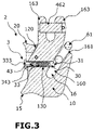
- the attachment system 1 comprises a main body 10 which has a groove 16 capable of receiving a link 61 of the chain 6.
- the stud 30 makes it possible to trap the link 61 to prevent it from coming out of the groove 16, when the link 61 is in the state introduced into the groove 16 in a position where the opening of the link is located opposite the stud. 30.
- the stud 30 In the active position of the stud 30, the stud 30 extends into the groove 16 and into the opening of the link 61 thus forming a barrier preventing the exit of the link relative to the groove 16 of the main body 10.
- the stud 30 protrudes inside the groove 16 of the main body 10 intended to receive the chain link 61, so as to at least partially close the passage 160 inside the groove. 16.
- the peak 30 prevents the exit of the chain link relative to the main body.
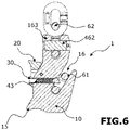
- the stud 30 frees the passage in the groove 16, which allows the link to be taken out of the groove or introduced into the groove.
- the peak 30 extends flush with or set back from the groove 16 of the main body intended to receive a chain link to allow said chain link to be freely introduced and removed. relative to the groove 16 of the main body.
- the end 31 of the locking stud 30 located on the side of the groove 16 has a face inclined with respect to the axis of movement of the stud 30.
- the normal to the inclined face 31 of the stud is oriented towards the opening zone 161 throat 16.
- the inclined face of the end of the piston thus forms a ramp, so that when the operator introduces the link into the groove 16 and the link presses against the inclined face of the peak 30, in a bearing direction oriented from the opening 161 of the groove 16 towards the bottom of the groove 16, the eyebolt 30 is moved, preferably by sliding, into the inactive position.
- the peak 30 is moved inside a through passage 130 made in the main body 10, to free the passage of the link 61 towards the bottom of the groove 16.
- a slot 343 is provided in the eyebolt 30.
- the light has a passage from an axis orthogonal to the axis of movement of the eyebolt 30.
- the system comprises a pin 43 which extends in the main body 10 and in or through said slot 343, and therefore through the through passage 130 in which the eyebolt 30 extends, to form an abutment of piton displacement limitation.
- pin 43 makes it possible to prevent any axial rotation of peak 30 on itself.
- a return spring 33 is configured to return the stud 30 to the active position. In the inactive position, the spring is compressed until the eyebolt 30 comes into abutment on the pin 43 by contact with the inner wall of its slot 343.
- the return spring 33 is located in a hollow part 333, preferably blind, of eyebolt 30 between pin 43 and the bottom of hollow part 333.
- the main body 10 is also provided with a trigger system 2.
- the 2 trigger system includes a trigger 20.
- the trigger 20 is manually operable to drive the peak 30 into the inactive position.
- the trigger 20 is intended to be acted upon by the operator's hand, for example the operator's index finger.
- the upper part of the trigger 20 has a curved shape, preferably concave, adapted to the positioning of a finger of the operator.
- the trigger 20 is coupled to the locking stud 30.
- a through passage 23 is provided in the trigger for the passage of the locking stud 30.
- the locking stud 30 has a head 32 of dimension greater than the width of the through passage to allow the trigger to press on this head when the trigger is moved by pressing the operator on the trigger.
- a movement of the trigger 20 causes a movement of the locking stud 30.
- the trigger 20 is movable from a first position in which the stud 30 is in the active position, to a second position to drive the stud 30 into the inactive position. Actuation of the trigger moves it from the first position to the second position, so that during this movement the trigger drives the peak from its active position to its inactive position.
- the second position of the trigger 20 corresponds to a position in which the operator presses (presses) the trigger so that the peak 30 is brought into the inactive position.
- the trigger 20 is movable, preferably sliding, in a direction inclined relative to the direction of movement of the peak 30. According to an embodiment illustrated in the figures, the direction in which the trigger 20 is movable is substantially parallel to the entry/exit axis of the link with respect to the groove.
- the trigger 20 is returned by a spring to the first position which corresponds to a high position of the trigger 20.
- the high position is considered in a configuration where the main body 10 is oriented so that its throat 16 is open upwards (as visible for example on the Figure 3 ).
- the peak 30 thus finds itself in the inactive position after having been driven by the trigger 20 when the trigger reaches the second position and as long as the trigger is maintained in this second position.
- this second position of the trigger corresponds to a pressed position of the trigger by the operator.
- the slope 120 along which the trigger 20 is moved makes it possible to transmit a force to the eyebolt 30 which has a component parallel to the axis of the eyebolt and directed towards the outside of the attachment system 1, which causes the eyebolt 30 to move opening of the groove (in the inactive position), which frees the passage inside the groove 16.
- the first position is a high position separated from the lug 15 presented below.
- the trigger system also preferably comprises an abutment 42 for limiting movement of the trigger 20.
- the abutment limits the movement of the trigger in the direction going from the first position to the second position.
- Said limit stop is for example formed by a pin 42.
- the trigger 20 has a slot 24 through which the pin 42 extends. The limit stop is formed by cooperation of the pin 42 and one end of the slot 24.
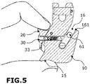
- the main body 10 comprises a part, called lug 15, the shape of which is adapted to allow the operator to, with one hand, press on the trigger 20 to push the stud 30 back into the inactive position, by positioning a finger, for example the thumb, under the lug 15, and another finger, for example the middle finger, on the trigger 20.
- the trigger 20 is moved by pressing the operator in the direction of this lug 15 when it is moved from the first position to the second position.
- Such a design of the lug 15 and the trigger 20, which allows the operator to position a thumb of one hand under the main body 10, in contact with the lug 15, and another finger of this same hand , such as the index finger, on the trigger 20 thus allows the operator to keep his other hand free to grasp the chain.
- the main body 10 also comprises a fixing yoke which includes an additional groove 162 defined between two lugs 163 of the main body 10.
- a through hole is made in each lug 163 to allow the passage of a pin 462 allowing to reduce or close the passage inside the groove 162 to imprison another link 62 of the chain or of another chain with respect to the main body 10.
- the pin 462 is removable to allow said link 62 to be released.
- the system comprises a locking system, which can be deactivated, making it possible to lock the pin 462 in the reduction or closing position of the passage inside the additional groove 162.
- the hooking system can comprise a hooking ring or eye making it possible to hook another link of the same chain or of another chain.
- the fixing yoke can be replaced by such a ring or hooking eye.
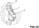
- the figure 10 which is a detail view of the X area of the figure 9 , shows the link of the chain trapped in the attachment system, the link of the other chain being trapped in the yoke of the attachment system.
- the attachment system presented above makes it possible to implement a method for attaching at least one link 61 of a chain using said attachment system.
- the peak 30 is moved to the inactive position.
- the link enters the groove in a position where the opening of the link 61 is located opposite the peak 30.
- the movement of the peak 30 in the inactive position can be controlled by pressing the trigger 20.
- the displacement of the peak in the inactive position is obtained by pressing the link 61 on the end 31 of the peak 30, so that the bearing force transmitted to the peak has a component which makes it possible to push the peak 30 in the direction of a release of the passage inside the groove (that is to say a displacement of the peak 30 towards its inactive position).
- the effort of inserting the link by the operator makes it possible both to move the stud 30 and to introduce the link 61 into the groove.
- the eyebolt is returned to the active position, preferably by the return force of the spring 33, inside the opening of the link so that the link 61 is imprisoned relative to the groove 16.
- the piton is repositioned in the opening of the link behind the part of the link which has just passed the piton.
- the hooking system thus makes it possible to obtain a simple and automatic locking of the chain during its insertion thanks to the configuration of the locking system which allows the link to push the locking stud back towards its inactive position, during insertion of the link in the throat.
- the trigger is located, in the inactive position, in the middle or upper part of the main body and the lug is located in the lower part of the main body.
- the trigger and the lug both have a support area of concave shape for better gripping, which makes it possible to actuate the unlocking by a clamp-type movement.
- the hooking system also allows quick and easy unlocking by pressing the trigger.
- the attachment system presented above makes it possible to implement a method for releasing at least one link 61 of a chain, trapped in a groove 16 of said attachment system.
- the or each chain used can be a lifting or supply chain.
- the or each chain may be of the short link type, for example grade 80,100 or 120.
- the attachment system can be used for a securing application, for example for securing a load 8 on a trailer 7, as illustrated in Figure 7 and 8 , or lifting a load 9 as illustrated in Figure 9 and 10 .
Landscapes
- Engineering & Computer Science (AREA)
- General Engineering & Computer Science (AREA)
- Mechanical Engineering (AREA)
- Transportation (AREA)
- Agricultural Machines (AREA)
- Hooks, Suction Cups, And Attachment By Adhesive Means (AREA)
- Vehicle Body Suspensions (AREA)
- Intermediate Stations On Conveyors (AREA)
- Transmissions By Endless Flexible Members (AREA)
Applications Claiming Priority (1)
| Application Number | Priority Date | Filing Date | Title |
|---|---|---|---|
| FR2102414A FR3120557B1 (fr) | 2021-03-11 | 2021-03-11 | Systeme d’accrochage pour chaine a maillons et procedes correspondants |
Publications (3)
| Publication Number | Publication Date |
|---|---|
| EP4056420A1 true EP4056420A1 (de) | 2022-09-14 |
| EP4056420B1 EP4056420B1 (de) | 2023-11-22 |
| EP4056420C0 EP4056420C0 (de) | 2023-11-22 |
Family
ID=75690510
Family Applications (1)
| Application Number | Title | Priority Date | Filing Date |
|---|---|---|---|
| EP22161609.7A Active EP4056420B1 (de) | 2021-03-11 | 2022-03-11 | Einhängesystem für gliederketten und entsprechende verfahren |
Country Status (3)
| Country | Link |
|---|---|
| EP (1) | EP4056420B1 (de) |
| ES (1) | ES2966754T3 (de) |
| FR (1) | FR3120557B1 (de) |
Citations (3)
| Publication number | Priority date | Publication date | Assignee | Title |
|---|---|---|---|---|
| GB1405513A (en) | 1973-06-05 | 1975-09-10 | Evans Martin Ltd | Shackles |
| GB2485639A (en) * | 2010-11-17 | 2012-05-23 | Balfour Beatty Plc | Remotely operable lifting shackle and actuation tool |
| US10458460B1 (en) * | 2017-08-22 | 2019-10-29 | Allan A. Fox | Spring-loaded safety latch release for power line hook |
-
2021
- 2021-03-11 FR FR2102414A patent/FR3120557B1/fr active Active
-
2022
- 2022-03-11 EP EP22161609.7A patent/EP4056420B1/de active Active
- 2022-03-11 ES ES22161609T patent/ES2966754T3/es active Active
Patent Citations (3)
| Publication number | Priority date | Publication date | Assignee | Title |
|---|---|---|---|---|
| GB1405513A (en) | 1973-06-05 | 1975-09-10 | Evans Martin Ltd | Shackles |
| GB2485639A (en) * | 2010-11-17 | 2012-05-23 | Balfour Beatty Plc | Remotely operable lifting shackle and actuation tool |
| US10458460B1 (en) * | 2017-08-22 | 2019-10-29 | Allan A. Fox | Spring-loaded safety latch release for power line hook |
Also Published As
| Publication number | Publication date |
|---|---|
| ES2966754T3 (es) | 2024-04-24 |
| EP4056420B1 (de) | 2023-11-22 |
| FR3120557B1 (fr) | 2023-03-17 |
| EP4056420C0 (de) | 2023-11-22 |
| FR3120557A1 (fr) | 2022-09-16 |
Similar Documents
| Publication | Publication Date | Title |
|---|---|---|
| EP0779951B1 (de) | Fernbedienbarer karabinerhaken, zum festmachen eines taues | |
| EP0826890B1 (de) | Karabinerhaken mit Verriegelungsvorrichtung | |
| FR2883938A1 (fr) | Mousqueton a verrouillage automatique | |
| FR2883344A1 (fr) | Mousqueton a bague de verrouillage | |
| EP2243972A1 (de) | Verbindungsglied mit verriegelbarem Drehring | |
| FR2585610A1 (fr) | Pince de traction et de coupe pour laniere, en particulier pour collier de serrage | |
| EP1985417B1 (de) | Sicherheitsmesser mit automatischem Rückzugsmechanismus der Schneide nach Beenden des Schneidevorgangs | |
| FR2474432A1 (fr) | Dispositif d'ancrage pour tige d'ancrage marine | |
| EP0644340A2 (de) | Karabinerhaken-Vorrichtung, besonders für Boote | |
| EP4056420B1 (de) | Einhängesystem für gliederketten und entsprechende verfahren | |
| EP4137706B1 (de) | Vorrichtung und verfahren zum montieren von rohren | |
| FR2478969A1 (fr) | Dispositif d'accouplement pour accrocher un porte-cles | |
| EP0626494B1 (de) | Betätigungseinrichtung für die automatische Verriegelung eines Fensterflügels oder dergleichen | |
| EP0047697A1 (de) | Vorrichtung zum unverletzlichen Zusammenfügen von Einzelteilen, wie Erkennungsplaketten von Vieh | |
| FR3047759A1 (fr) | Bequille de porte pour montage et demontage rapide | |
| EP3276094B1 (de) | Wasserspülungsmechanismus, der einen druckknopf umfasst, der in der lage ist, eine wasserspülung beim übergang von der gedrückten position in die ruheposition auszulösen | |
| EP3885592B1 (de) | Blindmontageanordnung eines bremsseils an einem betätigungshebel einer kraftfahrzeug-trommelbremse und montageverfahren | |
| FR2907522A1 (fr) | Dispositif de fixation d'un premier sous-ensemble sur un second sous-ensemble de vehicule automobile. | |
| FR3075847A1 (fr) | Verrou et trappe comprenant un tel verrou | |
| CH687774A5 (fr) | Fixation d'un outil à l'extrémité d'un bras de machine de chantier. | |
| EP3512742B1 (de) | Vorrichtung zur befestigung einer leiter am fahrzeugdach | |
| EP1049847B1 (de) | Diebstahlsicherungsdose | |
| FR3008444A1 (fr) | Dispositif d'accouplement entre un axe d'actionnement et une cavite interne d'une bequille de manipulation de serrure et ensemble axe et bequille de serrure comprenant un tel dispositif | |
| WO1989008413A1 (fr) | Fermoir de securite | |
| FR2849146A1 (fr) | Collier de serrage debrayable |
Legal Events
| Date | Code | Title | Description |
|---|---|---|---|
| PUAI | Public reference made under article 153(3) epc to a published international application that has entered the european phase |
Free format text: ORIGINAL CODE: 0009012 |
|
| STAA | Information on the status of an ep patent application or granted ep patent |
Free format text: STATUS: THE APPLICATION HAS BEEN PUBLISHED |
|
| AK | Designated contracting states |
Kind code of ref document: A1 Designated state(s): AL AT BE BG CH CY CZ DE DK EE ES FI FR GB GR HR HU IE IS IT LI LT LU LV MC MK MT NL NO PL PT RO RS SE SI SK SM TR |
|
| STAA | Information on the status of an ep patent application or granted ep patent |
Free format text: STATUS: REQUEST FOR EXAMINATION WAS MADE |
|
| 17P | Request for examination filed |
Effective date: 20230131 |
|
| RAV | Requested validation state of the european patent: fee paid |
Extension state: TN Effective date: 20230131 Extension state: MA Effective date: 20230131 |
|
| RBV | Designated contracting states (corrected) |
Designated state(s): AL AT BE BG CH CY CZ DE DK EE ES FI FR GB GR HR HU IE IS IT LI LT LU LV MC MK MT NL NO PL PT RO RS SE SI SK SM TR |
|
| RIC1 | Information provided on ipc code assigned before grant |
Ipc: F16G 15/06 20060101ALI20230704BHEP Ipc: B60P 7/08 20060101AFI20230704BHEP |
|
| GRAP | Despatch of communication of intention to grant a patent |
Free format text: ORIGINAL CODE: EPIDOSNIGR1 |
|
| STAA | Information on the status of an ep patent application or granted ep patent |
Free format text: STATUS: GRANT OF PATENT IS INTENDED |
|
| INTG | Intention to grant announced |
Effective date: 20230824 |
|
| GRAS | Grant fee paid |
Free format text: ORIGINAL CODE: EPIDOSNIGR3 |
|
| GRAA | (expected) grant |
Free format text: ORIGINAL CODE: 0009210 |
|
| STAA | Information on the status of an ep patent application or granted ep patent |
Free format text: STATUS: THE PATENT HAS BEEN GRANTED |
|
| AK | Designated contracting states |
Kind code of ref document: B1 Designated state(s): AL AT BE BG CH CY CZ DE DK EE ES FI FR GB GR HR HU IE IS IT LI LT LU LV MC MK MT NL NO PL PT RO RS SE SI SK SM TR |
|
| REG | Reference to a national code |
Ref country code: GB Ref legal event code: FG4D Free format text: NOT ENGLISH |
|
| REG | Reference to a national code |
Ref country code: CH Ref legal event code: EP |
|
| REG | Reference to a national code |
Ref country code: DE Ref legal event code: R096 Ref document number: 602022001051 Country of ref document: DE |
|
| REG | Reference to a national code |
Ref country code: IE Ref legal event code: FG4D Free format text: LANGUAGE OF EP DOCUMENT: FRENCH |
|
| U01 | Request for unitary effect filed |
Effective date: 20231218 |
|
| U07 | Unitary effect registered |
Designated state(s): AT BE BG DE DK EE FI FR IT LT LU LV MT NL PT SE SI Effective date: 20240102 |
|
| PG25 | Lapsed in a contracting state [announced via postgrant information from national office to epo] |
Ref country code: GR Free format text: LAPSE BECAUSE OF FAILURE TO SUBMIT A TRANSLATION OF THE DESCRIPTION OR TO PAY THE FEE WITHIN THE PRESCRIBED TIME-LIMIT Effective date: 20240223 |
|
| PG25 | Lapsed in a contracting state [announced via postgrant information from national office to epo] |
Ref country code: IS Free format text: LAPSE BECAUSE OF FAILURE TO SUBMIT A TRANSLATION OF THE DESCRIPTION OR TO PAY THE FEE WITHIN THE PRESCRIBED TIME-LIMIT Effective date: 20240322 |
|
| REG | Reference to a national code |
Ref country code: ES Ref legal event code: FG2A Ref document number: 2966754 Country of ref document: ES Kind code of ref document: T3 Effective date: 20240424 |
|
| PG25 | Lapsed in a contracting state [announced via postgrant information from national office to epo] |
Ref country code: IS Free format text: LAPSE BECAUSE OF FAILURE TO SUBMIT A TRANSLATION OF THE DESCRIPTION OR TO PAY THE FEE WITHIN THE PRESCRIBED TIME-LIMIT Effective date: 20240322 Ref country code: GR Free format text: LAPSE BECAUSE OF FAILURE TO SUBMIT A TRANSLATION OF THE DESCRIPTION OR TO PAY THE FEE WITHIN THE PRESCRIBED TIME-LIMIT Effective date: 20240223 |
|
| PG25 | Lapsed in a contracting state [announced via postgrant information from national office to epo] |
Ref country code: RS Free format text: LAPSE BECAUSE OF FAILURE TO SUBMIT A TRANSLATION OF THE DESCRIPTION OR TO PAY THE FEE WITHIN THE PRESCRIBED TIME-LIMIT Effective date: 20231122 Ref country code: PL Free format text: LAPSE BECAUSE OF FAILURE TO SUBMIT A TRANSLATION OF THE DESCRIPTION OR TO PAY THE FEE WITHIN THE PRESCRIBED TIME-LIMIT Effective date: 20231122 Ref country code: NO Free format text: LAPSE BECAUSE OF FAILURE TO SUBMIT A TRANSLATION OF THE DESCRIPTION OR TO PAY THE FEE WITHIN THE PRESCRIBED TIME-LIMIT Effective date: 20240222 Ref country code: HR Free format text: LAPSE BECAUSE OF FAILURE TO SUBMIT A TRANSLATION OF THE DESCRIPTION OR TO PAY THE FEE WITHIN THE PRESCRIBED TIME-LIMIT Effective date: 20231122 |
|
| PG25 | Lapsed in a contracting state [announced via postgrant information from national office to epo] |
Ref country code: CZ Free format text: LAPSE BECAUSE OF FAILURE TO SUBMIT A TRANSLATION OF THE DESCRIPTION OR TO PAY THE FEE WITHIN THE PRESCRIBED TIME-LIMIT Effective date: 20231122 |
|
| PG25 | Lapsed in a contracting state [announced via postgrant information from national office to epo] |
Ref country code: SK Free format text: LAPSE BECAUSE OF FAILURE TO SUBMIT A TRANSLATION OF THE DESCRIPTION OR TO PAY THE FEE WITHIN THE PRESCRIBED TIME-LIMIT Effective date: 20231122 |
|
| PG25 | Lapsed in a contracting state [announced via postgrant information from national office to epo] |
Ref country code: SM Free format text: LAPSE BECAUSE OF FAILURE TO SUBMIT A TRANSLATION OF THE DESCRIPTION OR TO PAY THE FEE WITHIN THE PRESCRIBED TIME-LIMIT Effective date: 20231122 Ref country code: SK Free format text: LAPSE BECAUSE OF FAILURE TO SUBMIT A TRANSLATION OF THE DESCRIPTION OR TO PAY THE FEE WITHIN THE PRESCRIBED TIME-LIMIT Effective date: 20231122 Ref country code: RO Free format text: LAPSE BECAUSE OF FAILURE TO SUBMIT A TRANSLATION OF THE DESCRIPTION OR TO PAY THE FEE WITHIN THE PRESCRIBED TIME-LIMIT Effective date: 20231122 Ref country code: CZ Free format text: LAPSE BECAUSE OF FAILURE TO SUBMIT A TRANSLATION OF THE DESCRIPTION OR TO PAY THE FEE WITHIN THE PRESCRIBED TIME-LIMIT Effective date: 20231122 |
|
| REG | Reference to a national code |
Ref country code: DE Ref legal event code: R097 Ref document number: 602022001051 Country of ref document: DE |
|
| U21 | Renewal fee for the european patent with unitary effect paid with additional fee |
Year of fee payment: 3 Effective date: 20240724 |
|
| PLBE | No opposition filed within time limit |
Free format text: ORIGINAL CODE: 0009261 |
|
| STAA | Information on the status of an ep patent application or granted ep patent |
Free format text: STATUS: NO OPPOSITION FILED WITHIN TIME LIMIT |
|
| 26N | No opposition filed |
Effective date: 20240823 |
|
| PG25 | Lapsed in a contracting state [announced via postgrant information from national office to epo] |
Ref country code: MC Free format text: LAPSE BECAUSE OF FAILURE TO SUBMIT A TRANSLATION OF THE DESCRIPTION OR TO PAY THE FEE WITHIN THE PRESCRIBED TIME-LIMIT Effective date: 20231122 |
|
| PG25 | Lapsed in a contracting state [announced via postgrant information from national office to epo] |
Ref country code: MC Free format text: LAPSE BECAUSE OF FAILURE TO SUBMIT A TRANSLATION OF THE DESCRIPTION OR TO PAY THE FEE WITHIN THE PRESCRIBED TIME-LIMIT Effective date: 20231122 |
|
| PG25 | Lapsed in a contracting state [announced via postgrant information from national office to epo] |
Ref country code: IE Free format text: LAPSE BECAUSE OF NON-PAYMENT OF DUE FEES Effective date: 20240311 |
|
| PG25 | Lapsed in a contracting state [announced via postgrant information from national office to epo] |
Ref country code: IE Free format text: LAPSE BECAUSE OF NON-PAYMENT OF DUE FEES Effective date: 20240311 |
|
| U20 | Renewal fee for the european patent with unitary effect paid |
Year of fee payment: 4 Effective date: 20250325 |
|
| PGFP | Annual fee paid to national office [announced via postgrant information from national office to epo] |
Ref country code: ES Payment date: 20250404 Year of fee payment: 4 |
|
| PG25 | Lapsed in a contracting state [announced via postgrant information from national office to epo] |
Ref country code: CY Free format text: LAPSE BECAUSE OF FAILURE TO SUBMIT A TRANSLATION OF THE DESCRIPTION OR TO PAY THE FEE WITHIN THE PRESCRIBED TIME-LIMIT; INVALID AB INITIO Effective date: 20220311 |
|
| REG | Reference to a national code |
Ref country code: CH Ref legal event code: H13 Free format text: ST27 STATUS EVENT CODE: U-0-0-H10-H13 (AS PROVIDED BY THE NATIONAL OFFICE) Effective date: 20251023 |
|
| VS25 | Lapsed in a validation state [announced via postgrant information from nat. office to epo] |
Ref country code: MA Free format text: FAILURE TO ELECT DOMICILE IN THE NATIONAL COUNTRY Effective date: 20240223 |
|
| PG25 | Lapsed in a contracting state [announced via postgrant information from national office to epo] |
Ref country code: TR Free format text: LAPSE BECAUSE OF FAILURE TO SUBMIT A TRANSLATION OF THE DESCRIPTION OR TO PAY THE FEE WITHIN THE PRESCRIBED TIME-LIMIT Effective date: 20231122 |
|
| PG25 | Lapsed in a contracting state [announced via postgrant information from national office to epo] |
Ref country code: CH Free format text: LAPSE BECAUSE OF NON-PAYMENT OF DUE FEES Effective date: 20250331 |
|
| U20 | Renewal fee for the european patent with unitary effect paid |
Year of fee payment: 5 Effective date: 20260326 |