EP4056445B1 - Eisenbahnwagen zum transport von aufliegern und dergleichen - Google Patents
Eisenbahnwagen zum transport von aufliegern und dergleichen Download PDFInfo
- Publication number
- EP4056445B1 EP4056445B1 EP22171408.2A EP22171408A EP4056445B1 EP 4056445 B1 EP4056445 B1 EP 4056445B1 EP 22171408 A EP22171408 A EP 22171408A EP 4056445 B1 EP4056445 B1 EP 4056445B1
- Authority
- EP
- European Patent Office
- Prior art keywords
- leg
- railway wagon
- beam assembly
- foot
- carrying section
- Prior art date
- Legal status (The legal status is an assumption and is not a legal conclusion. Google has not performed a legal analysis and makes no representation as to the accuracy of the status listed.)
- Active
Links
Images
Classifications
-
- B—PERFORMING OPERATIONS; TRANSPORTING
- B61—RAILWAYS
- B61D—BODY DETAILS OR KINDS OF RAILWAY VEHICLES
- B61D47/00—Loading or unloading devices combined with vehicles, e.g. loading platforms, doors convertible into loading and unloading ramps
- B61D47/005—Loading or unloading devices combined with road vehicles carrying wagons, e.g. ramps, turntables, lifting means
-
- B—PERFORMING OPERATIONS; TRANSPORTING
- B61—RAILWAYS
- B61D—BODY DETAILS OR KINDS OF RAILWAY VEHICLES
- B61D3/00—Wagons or vans
- B61D3/16—Wagons or vans adapted for carrying special loads
- B61D3/18—Wagons or vans adapted for carrying special loads for vehicles
- B61D3/182—Wagons or vans adapted for carrying special loads for vehicles specially adapted for heavy vehicles, e.g. public work vehicles, trucks, trailers
- B61D3/184—Wagons or vans adapted for carrying special loads for vehicles specially adapted for heavy vehicles, e.g. public work vehicles, trucks, trailers the heavy vehicles being of the trailer or semi-trailer type
-
- B—PERFORMING OPERATIONS; TRANSPORTING
- B61—RAILWAYS
- B61D—BODY DETAILS OR KINDS OF RAILWAY VEHICLES
- B61D15/00—Other railway vehicles, e.g. scaffold cars; Adaptations of vehicles for use on railways
-
- B—PERFORMING OPERATIONS; TRANSPORTING
- B61—RAILWAYS
- B61D—BODY DETAILS OR KINDS OF RAILWAY VEHICLES
- B61D17/00—Construction details of vehicle bodies
- B61D17/04—Construction details of vehicle bodies with bodies of metal; with composite, e.g. metal and wood body structures
-
- B—PERFORMING OPERATIONS; TRANSPORTING
- B61—RAILWAYS
- B61D—BODY DETAILS OR KINDS OF RAILWAY VEHICLES
- B61D3/00—Wagons or vans
- B61D3/04—Wagons or vans with movable floors, e.g. rotatable or floors which can be raised or lowered
-
- B—PERFORMING OPERATIONS; TRANSPORTING
- B61—RAILWAYS
- B61D—BODY DETAILS OR KINDS OF RAILWAY VEHICLES
- B61D45/00—Means or devices for securing or supporting the cargo, including protection against shocks
-
- B—PERFORMING OPERATIONS; TRANSPORTING
- B61—RAILWAYS
- B61D—BODY DETAILS OR KINDS OF RAILWAY VEHICLES
- B61D47/00—Loading or unloading devices combined with vehicles, e.g. loading platforms, doors convertible into loading and unloading ramps
Definitions
- the present invention relates to a railway wagon for transportation of semitrailers and the like.
- a load-carrying section of the railway wagon is turned out from and back to the railway wagon.
- a beam which can be moved out from the railway wagon.
- a ground support which often-times has the shape of a telescopic supporting member.
- the support is moved by means of a vertically operated jack which is configured to lower the support until it rests on the ground in order to support the beam as the load-carrying section is turned out from or back to the railway wagon.
- An object of the present invention is to solve or at least mitigate the problems related to prior-art structures. This object has now been achieved by a railway wagon having the features set forth in appended claim 1 which defines the invention. Preferred embodiments are recited in the related dependent claims.
- a railway wagon configured to carry a semitrailer or the like.
- the railway wagon comprises a first bogie, a second bogie and a carrying section therebetween.
- the carrying section is movable between a first position in which it extends between the two bogies, and a second position in which the carrying section is turned out from the railway wagon for loading and unloading of a semitrailer.
- the railway wagon comprises a beam assembly configured to be moved out from and back to the railway wagon and to support a front portion of the carrying section.
- the beam assembly comprises a leg which is arranged at an outer end of the beam assembly, and which is configured to support against the ground.
- the beam assembly comprises an actuator configured to lower and raise the leg which has a foot at its free end configured to abut the ground.
- the actuator is arranged substantially in parallel with a main extension of the beam assembly.
- a force or pressure sensing device is arranged in connection with the foot of the beam assembly leg.
- the force or pressure sensing device comprises a sensor configured to send signals to control systems ensuring that correct pressure or load is put on the foot and thereby on the leg and the entire beam assembly.
- the sensing device is configured to sense when the foot gets into contact with the ground and to send signals to the actuator which controls the movements of the foot.
- the beam assembly Thanks to the beam assembly, loads that are not entirely vertical can be taken. Furthermore, the risk of breaking the actuator, which may be a hydraulic cylinder, is reduced.
- the beam assembly When a semitrailer is to be loaded onto the railway wagon, the beam assembly is moved out from the wagon to an active position in which it guides the front portion of the carrying section being turned out to its loading position. The beam assembly is moved back to the wagon and the semitrailer is driven onto the lowered, sloping carrying section which is raised after loading. Then the beam assembly is moved out again and guides the front portion of the raised carrying section (with the semitrailer thereon) back to the wagon position. Finally, the beam assembly is moved back to the wagon which is now ready for railway transportation.
- the beam assembly may be provided with pivots and links which serve to achieve secure ground support of the beam in its active position moved out from the wagon.
- This system of pivots and links is arranged at the free end of the beam assembly and it is connected to and configured to move the leg of the beam.
- the railway wagon may have a slide of a king pin locking system arranged moveable by means of two cylinders.
- the two cylinders are connected to a reservoir via a spring-loaded valve to act as dampers.
- the railway wagon may further comprise a channel for conduits extending between the first bogie and the second bogie.
- the channel is configured to be automatically lowered in a mechanical way when the carrying section is turned out to the second position.
- This railway wagon structure is advantageous since the different kinds of conduits - such as air supply pipes, hydraulic oil supply tubes, and power supply cables - can be kept safely together in the channel which is also referred to as a media channel.
- the conduits are received in the media channel and protected therein during railway transportation and during loading and unloading of semitrailers, when the carrying section is turned out and turned back in relation to the railway wagon.
- the channel is arranged beneath the carrying section which means that the turning movement of the same can be performed in a safe manner.
- One end portion of the channel may be received moveable on a bar having a sloping part.
- the channel has a roller received on the bar.
- a railway wagon 1 which is adapted for receiving a semitrailer 2.
- the railway wagon 1 comprises a first bogie 3 and a second bogie 4, placed at opposite ends of a load-carrying section 5.
- the carrying section 5 may be turned outwards and lowered to make it possible to drive the semitrailer 2 onto the section 5.
- the carrying section 5 is pivotally connected to the second bogie 4 by means of pivot means (not shown) which make it possible to turn or "swing" the section 5 to the position shown in Fig. 1 .
- pivot means not shown
- a beam 6 is moved out from the first bogie 3 of the railway wagon 1.
- the beam 6 is supported by a telescopic leg 7, in the form of a hydraulic cylinder, at an outer end.
- the hydraulic cylinder is placed and works in a vertical direction.
- the beam 6 is moved back to the first bogie 3, in order for allowing a semitrailer 2 to be brought onto the carrying section 5.
- the beam 6 is moved back out again, to turn the load-carrying section 5 back in line with the first and second bogies 3, 4.
- the railway wagon 1 is provided with means (not shown) for lowering and raising the front portion 1a of the carrying section 5.
- the position shown in Fig. 2 is also referred to as the first or transportation position whereas the position shown in Fig. 1 is referred to as the second position for loading or unloading of a semitrailer 2 or the like.
- the carrying section 5 serves as a ramp for the semitrailer 2 to be driven onto the carrying section 5 to perform transportation by the railway wagon 1, or driven down from the carrying section 5 when the destination has been reached.
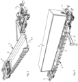
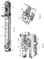
- a railway wagon 1' which has the same basic structure as the railway wagon 1 of Figs 1-2 but which is provided with a modified beam assembly 8 arranged to be moved out from and in to the first bogie 3 when the load-carrying section 5 is to be turned out or back.
- the improved beam assembly 8 is mounted to the railway wagon 1' and it comprises an actuator, preferably a hydraulic cylinder 9, which extends substantially in parallel to the axis of the beam. By this placement of the hydraulic cylinder 9, this cylinder is in parallel with the main extension of the beam assembly 8.
- an outer end of a piston of the hydraulic cylinder 9 is connected to a first end of a leg 10.
- a foot 11 is placed at a second end of the leg 10.
- the hydraulic cylinder 9 is connected to the leg 10 by means of a first pivot 12, and the foot 11 is connected to the leg 10 by means of a second pivot 13.
- a link 14 is placed between the beam body and the leg 10.
- the link 14 is connected to an outer end of the beam assembly 8 by means of a third pivot 15 and to the leg 10 by means of a fourth pivot 16.
- the link 14 is connected to the leg 10 in a position between the first and second ends of the leg 10.
- the end of the leg 10 at the hydraulic cylinder 9 is placed on a sliding member 8A which is connected to a rail 8B mounted to the beam assembly 8.
- the sliding member 8A is free to move along the rail 8B and thereby along the beam assembly 8.
- the sliding member 8A is not free to move in a vertical direction and, thus, the hydraulic cylinder 9 is kept in parallel with a main extension of the beam assembly 8.
- the leg 10 is formed of two parallel plates. However, a person skilled in the art realizes that the leg 10 can have different designs.
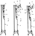
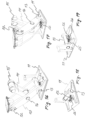
- the leg 10 When the piston of the hydraulic cylinder 9 is fully retracted, the leg 10 has a horizontal position at the beam assembly 8, as shown in Fig. 5 .
- the beam assembly 8 represents a compact unit without any parts protruding downwards from the beam body. This is an advantage when the beam assembly 8 is moved between the idle position at the wagon 1' and the active position transverse to the wagon 1'.
- the piston of the hydraulic cylinder 9 is pushed out. Due to the link 14 placed between the beam body and the leg 10, this leg will be turned downwardly. The leg 10 will be lowered until the foot 11 hits the ground G, as shown in Fig. 6 (see also Figs 3-4 ). As the foot 11 is connected to the leg 10 by means of the second pivot 13, the foot 11 can be securely placed also on a sloping ground.
- the leg 10 and link 14 form a kind of scissor linkage which can take up forces in several directions.
- the hydraulic cylinder 9 As the hydraulic cylinder 9 is horizontally placed at the beam assembly 8, it has a well defined position and working area, and it will not be exposed to any skewed forces irrespectively of the direction of forces on the foot 11 from the ground G.
- the railway wagon 1' provided with the improved beam assembly 8 operates in the following manner.
- the beam assembly 8 is moved out from the wagon 1' to an active position, in which it guides the front portion 1a of the carrying section 5 being turned out to its loading position.
- the beam assembly 8 is moved back to the wagon 1' and the semitrailer 2 is driven onto the lowered, sloping carrying section 5 which is raised after loading.
- the beam assembly 8 is moved out again to the position transverse to the longitudinal axis of the wagon 1' and guides the front portion 1a of the raised load-carrying section 5 (with the semitrailer thereon) back to wagon position.
- the beam assembly 8 is moved back to the wagon 1' which is ready for railway transportation.
- the railway wagon 1' is provided with means (not shown) for lowering and raising the front portion 1a of the carrying section 5.
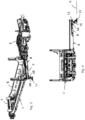
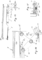
- the railway wagon 1' of Figs 8-9 includes conduits for hydraulic, air and electronics (not shown) extending from the first bogie 3 to the second bogie 4 at opposite ends of the railway wagon 1'.
- An elongated channel 17 is provided for these conduits. Hence, the conduits are safely kept together in the channel 17.
- the channel 17 extends between the first bogie 3 and the second bogie 4.
- One end portion of the channel 17 is pivotally connected to the second bogie 4 by means of pivot means (not shown).
- the channel 17 - which is also referred to as a media channel for receiving conduits - is supported on a bar 18 at the second bogie 4.
- the channel 17 has a roller 17A adapted to follow the bar 18.
- the bar 18 has a sloping part 19 being at the highest point in the position when the carrying section 5 is turned back onto the railway wagon 1'.
- the roller 17A of the channel 17 will go downwards along the sloping rail part 19, thereby lowering the channel 17.
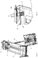
- the railway wagon 1' of Figs 10-12 includes a system for locking a king pin of the semitrailer 2 when the semitrailer 2 is in position on the railway wagon 1'.
- This system comprises a slide 20 which is moveable to catch the king pin (not shown).
- the slide 20 is moved back and forth in a longitudinal direction along the center axis of the wagon by means of two hydraulic cylinders 20A.
- the cylinders 20A act as dampers in case the railway wagon 1' would experience any bumps, for instance if railway wagons run in to each other.
- This dampening effect is achieved in that a reservoir (not shown) is provided for the oil of the cylinders 21 and that a spring-loaded valve is provided (not shown), which valve at a certain predetermined pressure will let oil through from the cylinders 21 to the reservoir.
- a reservoir (not shown) is provided for the oil of the cylinders 21 and that a spring-loaded valve is provided (not shown), which valve at a certain predetermined pressure will let oil through from the cylinders 21 to the reservoir.
- a force or pressure sensing device is arranged in connection with the foot 11.
- This sensing device includes an actuating member 22, 23 having an upper portion 22 in engagement with the pivot 13 of the foot 11, and a lower portion 23 projecting downwardly from the upper portion 22.
- a number of annular cup springs 25 surround the lower portion 22 of actuating member 22, 23.
- the cup springs 25 can be of the type referred to as Belleville washers.
- the downwardly projecting portion 23 is placed just above an opening 24 in the bottom plate of the foot 11.
- the pivot 13 presses against the upper portion 22 of the actuating member 22, 23 which means that the downwardly projecting portion 23 is inserted in the opening 24 against the action of the cup springs 25.
- This movement is detected by the sensor 26 which is configured to send signals to control systems (not shown) ensuring that the correct pressure or load is put on the foot 11, and thereby on the leg 10 as well as the entire beam assembly 8.
- the sensing device 22-26 senses when the foot 11 gets into contact with the ground G and can send signals to the actuating cylinder 9 which controls the movements of the foot 11 via the assembly of links, legs and pivots 10-16.
- actuating cylinder 9 which controls the movements of the foot 11 via the assembly of links, legs and pivots 10-16.
- the improved railway wagon can be used for transportation not only of semitrailers, but also tractors, haulers and the like.
- the movement of the beam assembly out from the wagon body to its active position can be performed in different ways.
- One option is to mount the beam assembly turnable or pivotable about a vertical pivot provided on the wagon.
- Another option is to arrange the beam assembly slideable in a direction substantially transverse the longitudinal axis of the wagon (the beam is slided out to its active position).
- the actuator of the beam assembly can be of different design.
- the actuator can also be pneumatically or electro-mechanically operated.
Landscapes
- Engineering & Computer Science (AREA)
- Mechanical Engineering (AREA)
- Transportation (AREA)
- Life Sciences & Earth Sciences (AREA)
- Wood Science & Technology (AREA)
- Vehicle Cleaning, Maintenance, Repair, Refitting, And Outriggers (AREA)
- Machines For Laying And Maintaining Railways (AREA)
- Handcart (AREA)
- Vehicle Body Suspensions (AREA)
- Railway Tracks (AREA)
- Vehicle Waterproofing, Decoration, And Sanitation Devices (AREA)
- Loading Or Unloading Of Vehicles (AREA)
- Steering-Linkage Mechanisms And Four-Wheel Steering (AREA)
Claims (11)
- Eisenbahnwaggon, der dafür ausgelegt ist, einen Sattelauflieger (2) oder dergleichen zu tragen, wobei der Eisenbahnwaggon ein erstes Drehgestell (3), ein zweites Drehgestell (4) und einen Tragabschnitt (5) umfasst; wobei der Tragabschnitt (5) bewegbar ist zwischen einer ersten Position, in der er sich zwischen den Drehgestellen (3, 4) erstreckt, und einer zweiten Position, in der der Tragabschnitt (5) zum Beladen und Entladen eines Sattelaufliegers (2) aus dem Eisenbahnwaggon herausgedreht ist;
wobei der Eisenbahnwaggon eine Trägeranordnung (8) umfasst, die dafür ausgelegt ist, aus dem Eisenbahnwaggon heraus und zurück in diesen bewegt zu werden und einen vorderen Abschnitt (1a) des Tragabschnitts (5) zu stützen; wobei die Trägeranordnung (8) einen Schenkel (10) umfasst, der an einem äußeren Ende der Trägeranordnung (8) angeordnet ist und zum Abstützen gegen den Boden (G) ausgelegt ist; wobei die Trägeranordnung (8) ferner einen Stellmotor (9) umfasst, der dafür ausgelegt ist, den Schenkel (10) abzusenken und anzuheben; und wobei der Trägeranordnungsschenkel (10) einen Fuß (11) an seinem freien Ende aufweist, wobei der Fuß (11) dafür ausgelegt ist, auf dem Boden (G) aufzuliegen; dadurch gekennzeichnet, dass der Stellmotor (9) im Wesentlichen parallel zu einer Haupterstreckung der Trägeranordnung (8) angeordnet ist; dass eine Kraft- oder Druckerfassungsvorrichtung (22-26) in Verbindung mit dem Fuß (11) des Trägeranordnungsschenkels (10) angeordnet ist; dass die Kraft- oder Druckerfassungsvorrichtung (22-26) einen Sensor (26) umfasst, der dafür ausgelegt ist, Signale an Steuersysteme zu senden, um sicherzustellen, dass der richtige Druck oder die richtige Belastung auf den Fuß (11) und damit auf den Schenkel (10) und die gesamte Trägeranordnung (8) ausgeübt wird; und dass die Erfassungsvorrichtung (22-26) dafür ausgelegt ist, zu erfassen, wann der Fuß (11) in Kontakt mit dem Boden (G) kommt, und Signale an den Stellmotor (9), der die Bewegungen des Fußes (11) steuert, zu senden. - Eisenbahnwaggon nach Anspruch 1, wobei der Stellmotor einen Hydraulikzylinder (9) umfasst.
- Eisenbahnwaggon nach Anspruch 1 oder 2, wobei der Stellmotor (9) mit dem Schenkel (10) an einem ersten Drehgelenk (12) an einem ersten Ende des Schenkels (10) verbunden ist.
- Eisenbahnwaggon nach Anspruch 3, wobei der Fuß (11) mit dem Schenkel (10) an einem zweiten Drehgelenk (13) an einem zweiten Ende des Schenkels (10) verbunden ist.
- Eisenbahnwaggon nach Anspruch 4, wobei ein Verbindungsglied (14) zwischen dem äußeren Ende der Trägeranordnung (8) und dem Schenkel (10) verbunden ist, und wobei das Verbindungsglied (14) mit dem Schenkel (10) an einem Punkt in einem Abstand zu dem ersten und dem zweiten Ende des Schenkels (10) verbunden ist.
- Eisenbahnwaggon nach Anspruch 5, wobei das Verbindungsglied (14) mit der Trägeranordnung (8) an einem dritten Drehgelenk (15) und mit dem Schenkel (10) an einem vierten Drehgelenk (16) verbunden ist.
- Eisenbahnwaggon nach Anspruch 6, wobei der Schenkel (10) und das Verbindungsglied (14) ein Scherengestänge bilden, das in der Lage ist, Kräfte in mehreren Richtungen aufzunehmen.
- Eisenbahnwaggon nach einem der Ansprüche 3-7, wobei das erste Ende des Schenkels (10) an einem Schiebeelement (8A) platziert ist, das entlang einer Schiene (8B) beweglich ist, die im Wesentlichen parallel zur Haupterstreckung der Trägeranordnung (8) befestigt ist.
- Eisenbahnwaggon nach Anspruch 2, wobei der Schenkel (10) - wenn ein Kolben des Hydraulikzylinders (9) vollständig eingefahren ist - eine horizontale Position aufweist, in der die Trägeranordnung (8) eine kompakte Einheit darstellt.
- Eisenbahnwaggon nach einem der vorhergehenden Ansprüche, wobei die Trägeranordnung (8) während ihrer Bewegung - von einer Ruheposition parallel zu dem Eisenbahnwaggon zu einer aktiven Position herausgedreht aus dem Eisenbahnwaggon in einer Richtung quer zu diesem - dafür ausgelegt ist, den vorderen Abschnitt (1a) des Tragabschnitts (5) zu führen.
- Eisenbahnwaggon nach einem der vorhergehenden Ansprüche, der ferner Mittel zum Absenken und Anheben des vorderen Abschnitts (1a) des Tragabschnitts (5) umfasst.
Priority Applications (1)
| Application Number | Priority Date | Filing Date | Title |
|---|---|---|---|
| EP23188776.1A EP4257534A3 (de) | 2018-10-24 | 2019-10-24 | Eisenbahnwagen zum transport von aufliegern und dergleichen |
Applications Claiming Priority (3)
| Application Number | Priority Date | Filing Date | Title |
|---|---|---|---|
| EP18202352 | 2018-10-24 | ||
| PCT/EP2019/079091 WO2020084081A1 (en) | 2018-10-24 | 2019-10-24 | Railway wagon for transportation of semitrailers and the like |
| EP19789726.7A EP3870492B8 (de) | 2018-10-24 | 2019-10-24 | Eisenbahnwagen zum transport von aufliegern und dergleichen |
Related Parent Applications (2)
| Application Number | Title | Priority Date | Filing Date |
|---|---|---|---|
| EP19789726.7A Division-Into EP3870492B8 (de) | 2018-10-24 | 2019-10-24 | Eisenbahnwagen zum transport von aufliegern und dergleichen |
| EP19789726.7A Division EP3870492B8 (de) | 2018-10-24 | 2019-10-24 | Eisenbahnwagen zum transport von aufliegern und dergleichen |
Related Child Applications (1)
| Application Number | Title | Priority Date | Filing Date |
|---|---|---|---|
| EP23188776.1A Division EP4257534A3 (de) | 2018-10-24 | 2019-10-24 | Eisenbahnwagen zum transport von aufliegern und dergleichen |
Publications (3)
| Publication Number | Publication Date |
|---|---|
| EP4056445A1 EP4056445A1 (de) | 2022-09-14 |
| EP4056445B1 true EP4056445B1 (de) | 2023-08-09 |
| EP4056445C0 EP4056445C0 (de) | 2023-08-09 |
Family
ID=63965532
Family Applications (3)
| Application Number | Title | Priority Date | Filing Date |
|---|---|---|---|
| EP23188776.1A Pending EP4257534A3 (de) | 2018-10-24 | 2019-10-24 | Eisenbahnwagen zum transport von aufliegern und dergleichen |
| EP19789726.7A Active EP3870492B8 (de) | 2018-10-24 | 2019-10-24 | Eisenbahnwagen zum transport von aufliegern und dergleichen |
| EP22171408.2A Active EP4056445B1 (de) | 2018-10-24 | 2019-10-24 | Eisenbahnwagen zum transport von aufliegern und dergleichen |
Family Applications Before (2)
| Application Number | Title | Priority Date | Filing Date |
|---|---|---|---|
| EP23188776.1A Pending EP4257534A3 (de) | 2018-10-24 | 2019-10-24 | Eisenbahnwagen zum transport von aufliegern und dergleichen |
| EP19789726.7A Active EP3870492B8 (de) | 2018-10-24 | 2019-10-24 | Eisenbahnwagen zum transport von aufliegern und dergleichen |
Country Status (11)
| Country | Link |
|---|---|
| US (2) | US12172682B2 (de) |
| EP (3) | EP4257534A3 (de) |
| KR (2) | KR20230073357A (de) |
| CN (2) | CN112912296B (de) |
| AU (2) | AU2019363715B2 (de) |
| ES (2) | ES2923274T3 (de) |
| HR (1) | HRP20220882T1 (de) |
| HU (1) | HUE059170T2 (de) |
| PL (1) | PL3870492T3 (de) |
| PT (1) | PT3870492T (de) |
| WO (1) | WO2020084081A1 (de) |
Families Citing this family (4)
| Publication number | Priority date | Publication date | Assignee | Title |
|---|---|---|---|---|
| DE102021104173B4 (de) | 2021-02-22 | 2024-03-21 | Hörmann Vehicle Engineering GmbH | Eisenbahnwagen mit einer Schwenkbrücke |
| DE202021100870U1 (de) | 2021-02-22 | 2022-05-30 | Hörmann Vehicle Engineering GmbH | Eisenbahnwagen mit einer Schwenkbrücke |
| EP4371842B1 (de) | 2022-11-15 | 2025-08-20 | Helrom GmbH | Eisenbahnwagen mit verbessertem stützträger |
| EP4371841A1 (de) | 2022-11-15 | 2024-05-22 | Helrom GmbH | Eisenbahnwagen mit verbesserter abschussträgerpositionierung |
Family Cites Families (34)
| Publication number | Priority date | Publication date | Assignee | Title |
|---|---|---|---|---|
| US732055A (en) | 1903-03-12 | 1903-06-30 | Arthur Donavan | Ratchet-wrench. |
| NL38472C (de) * | 1932-11-09 | |||
| GB496549A (en) * | 1937-05-26 | 1938-11-28 | Brockhouse J & Co Ltd | Improvements in or relating to road vehicles to facilitate loading and unloading |
| US3576167A (en) * | 1969-02-27 | 1971-04-27 | A F Kearney & Co | Apparatus for piggyback rail transportation |
| DE1961193C3 (de) | 1969-12-05 | 1973-11-22 | Gebr. Hofmann Maschinenfabrik Und Eisengiesserei, 8701 Eibelstadt | Abstützung für den Unterwagen eines fahrbaren Krans oder Baggers |
| US4202277A (en) * | 1977-06-27 | 1980-05-13 | Bi-Modal Corporation | Convertible rail-highway semi-trailer |
| ES287212Y (es) | 1985-05-21 | 1986-07-16 | Giribets Montal Salvador | Vagon para remolques de camiones y similares |
| SU1689165A1 (ru) | 1989-09-07 | 1991-11-07 | Всесоюзный Научно-Исследовательский Институт Вагоностроения | Железнодорожное транспортное средство дл перевозки колесной и гусеничной техники |
| US5567107A (en) * | 1992-11-16 | 1996-10-22 | Bruno; Michael R. | Extravehicular apparatus for loading and securing cargo |
| FR2810611B1 (fr) * | 2000-06-21 | 2002-10-04 | Lohr Ind | Dispositif de retenue en position relative des plates-formes d'extremite d'un wagon de transport combine rail/route lors des manoeuvres de chargements/dechargements |
| EP1348603A1 (de) | 2002-03-26 | 2003-10-01 | Felipe Bartos Castelo | Eisenbahngüterwagen für den Transport von Strassenfahrzeugen |
| GB2416532B (en) * | 2004-07-26 | 2007-10-24 | Cholerton Ltd | Pop-up mechanism |
| SE0402269L (sv) | 2004-09-17 | 2005-12-27 | Je Utveckling O Foervaltning A | Järnvägsvagn |
| US7320557B1 (en) * | 2004-10-05 | 2008-01-22 | Pro Barrier Engineering, Llc | Anti-terrorism vehicle security barrier |
| CZ296615B6 (cs) | 2005-01-20 | 2006-05-17 | KORSAKOV@Grigorij | Zeleznicní vagón pro prepravu rozmerných nákladu,zejména silnicních vozidel |
| DE202005015694U1 (de) * | 2005-10-06 | 2006-03-23 | Riedl, Reinhold, Dipl.-Ing. | Höhenverstellbare Stütze für Sattelauflieger o.dgl. |
| CN101475103A (zh) | 2009-01-23 | 2009-07-08 | 浙江理工大学 | 液压升降式槽罐运输装卸架 |
| US8505684B1 (en) * | 2009-02-05 | 2013-08-13 | Marc Bogue | Aerial work platform apparatus and method |
| RU2500560C2 (ru) * | 2009-04-16 | 2013-12-10 | К Текнолоджи АБ | Железнодорожный вагон и способ его загрузки |
| US20110280696A1 (en) | 2010-05-11 | 2011-11-17 | David Kun | Railroad Freight Car Loading Or Unloading |
| SE535162C2 (sv) | 2010-05-19 | 2012-05-02 | Sublift Ab | För en båttransportvagn anpassad armstruktur |
| ITPD20100196A1 (it) | 2010-06-23 | 2011-12-24 | Gastaldi Christian | Dispositivo stabilizzatore dell'assetto di lavoro e ripartitore di carico per macchine operatrici agricole e vivaistiche, e macchina operatrice particolarmente per il vivaismo dotata di un tale dispositivo stabilizzatore |
| CN103243918A (zh) | 2013-04-26 | 2013-08-14 | 三一汽车制造有限公司 | 一种臂架系统及具有其的作业设备 |
| CN103359128B (zh) * | 2013-08-06 | 2015-12-16 | 南车长江车辆有限公司 | 铁路冷藏车 |
| CN104527668B (zh) | 2015-01-05 | 2017-11-14 | 中车齐齐哈尔车辆有限公司 | 驮背运输车 |
| CN204341039U (zh) * | 2015-01-05 | 2015-05-20 | 齐齐哈尔轨道交通装备有限责任公司 | 铁路货车以及货运装卸系统 |
| CN204488797U (zh) | 2015-03-27 | 2015-07-22 | 齐齐哈尔轨道交通装备有限责任公司 | 驮背运输车 |
| CN204452455U (zh) * | 2015-03-27 | 2015-07-08 | 齐齐哈尔轨道交通装备有限责任公司 | 驮背运输车 |
| CN105016022B (zh) | 2015-07-09 | 2017-03-22 | 沅江市恒盛机械制造有限公司 | 船用环形皮带输送机 |
| PL3386830T3 (pl) | 2015-12-11 | 2020-05-18 | Flexiwaggon Ab | Urządzenie do zawieszania kabli i przewodów |
| FR3046124B1 (fr) * | 2015-12-24 | 2019-04-05 | Lohr Industrie | Systeme de verrouillage du pivot d'attelage d'une semi-remorque sur une unite ferroviaire |
| CN105584492B (zh) | 2016-03-10 | 2018-03-23 | 北京驮丰高新科技股份有限公司 | 一种驮背式运输用新型铁路货车 |
| CN106394681B (zh) * | 2016-11-10 | 2018-06-29 | 中车长江车辆有限公司 | 公铁两用车 |
| RU2700100C1 (ru) | 2018-07-13 | 2019-09-12 | Андрей Валентинович Жакалов | Контрейлерный вагон |
-
2019
- 2019-10-24 HU HUE19789726A patent/HUE059170T2/hu unknown
- 2019-10-24 EP EP23188776.1A patent/EP4257534A3/de active Pending
- 2019-10-24 AU AU2019363715A patent/AU2019363715B2/en active Active
- 2019-10-24 WO PCT/EP2019/079091 patent/WO2020084081A1/en not_active Ceased
- 2019-10-24 CN CN201980069245.0A patent/CN112912296B/zh active Active
- 2019-10-24 KR KR1020237016735A patent/KR20230073357A/ko active Pending
- 2019-10-24 EP EP19789726.7A patent/EP3870492B8/de active Active
- 2019-10-24 ES ES19789726T patent/ES2923274T3/es active Active
- 2019-10-24 PT PT197897267T patent/PT3870492T/pt unknown
- 2019-10-24 ES ES22171408T patent/ES2955375T3/es active Active
- 2019-10-24 HR HRP20220882TT patent/HRP20220882T1/hr unknown
- 2019-10-24 CN CN202310544838.6A patent/CN116803815A/zh active Pending
- 2019-10-24 PL PL19789726.7T patent/PL3870492T3/pl unknown
- 2019-10-24 EP EP22171408.2A patent/EP4056445B1/de active Active
- 2019-10-24 US US17/285,588 patent/US12172682B2/en active Active
- 2019-10-24 KR KR1020217015241A patent/KR102834088B1/ko active Active
-
2023
- 2023-02-20 AU AU2023200975A patent/AU2023200975B2/en active Active
-
2024
- 2024-10-09 US US18/910,244 patent/US20250026385A1/en active Pending
Also Published As
| Publication number | Publication date |
|---|---|
| HUE059170T2 (hu) | 2022-10-28 |
| AU2019363715A1 (en) | 2021-05-13 |
| AU2023200975B2 (en) | 2024-12-05 |
| EP3870492B8 (de) | 2022-06-22 |
| EP4257534A3 (de) | 2024-04-17 |
| US20250026385A1 (en) | 2025-01-23 |
| PL3870492T3 (pl) | 2022-08-29 |
| EP4257534A2 (de) | 2023-10-11 |
| KR102834088B1 (ko) | 2025-07-16 |
| EP4056445A1 (de) | 2022-09-14 |
| CN116803815A (zh) | 2023-09-26 |
| ES2923274T3 (es) | 2022-09-26 |
| ES2955375T3 (es) | 2023-11-30 |
| EP3870492B1 (de) | 2022-05-04 |
| CN112912296B (zh) | 2024-12-27 |
| HRP20220882T1 (hr) | 2022-10-28 |
| KR20210082199A (ko) | 2021-07-02 |
| CN112912296A (zh) | 2021-06-04 |
| AU2019363715B2 (en) | 2022-11-24 |
| PT3870492T (pt) | 2022-07-14 |
| US12172682B2 (en) | 2024-12-24 |
| BR112021006600A8 (pt) | 2022-10-04 |
| BR112021006600A2 (pt) | 2021-07-06 |
| AU2023200975A1 (en) | 2023-03-23 |
| US20210394804A1 (en) | 2021-12-23 |
| EP4056445C0 (de) | 2023-08-09 |
| WO2020084081A1 (en) | 2020-04-30 |
| EP3870492A1 (de) | 2021-09-01 |
| KR20230073357A (ko) | 2023-05-25 |
Similar Documents
| Publication | Publication Date | Title |
|---|---|---|
| US20250026385A1 (en) | Railway wagon for transportation of semi-trailers and the like | |
| US8667902B2 (en) | Railway wagon and a method of its loading | |
| CN101300184A (zh) | 移动转运装置 | |
| US4061353A (en) | Transport lock for lift bed trailer | |
| EP3548356B1 (de) | Verfahren und anordnung zum laden eines sattelaufliegers auf einen eisenbahnwagen | |
| US5876018A (en) | In-train wheel changing device | |
| US3018496A (en) | Mobile ramp | |
| US10351149B2 (en) | Rail car lifting device | |
| NL2004268C2 (en) | TRAILER FOR THE TRANSPORTATION BY ROAD OF CONTAINERS. | |
| US3075479A (en) | Railway car for freight trucks and the like | |
| KR101085546B1 (ko) | 컨테이너의 이/적재가 가능한 수평이송장치 | |
| RU2790995C2 (ru) | Железнодорожный вагон для транспортировки полуприцепов и транспортного средства, подобного полуприцепу | |
| US20060182567A1 (en) | Glass loading rack | |
| KR20110105600A (ko) | 컨테이너의 이/적재가 가능한 수평이송장치를 가지는 2중 모드 트레일러 및 컨테이너 이/적재 방법 | |
| EP3441277A1 (de) | Mechanismus zum heben von wagentragenden wageneinstiegsplatten | |
| JPS6111818B2 (de) | ||
| BR112021006600B1 (pt) | Vagão ferroviário configurado para conduzir um semirreboque ou elemento do gênero | |
| WO2011089308A1 (en) | Retaining arrangement within handling of load platforms |
Legal Events
| Date | Code | Title | Description |
|---|---|---|---|
| PUAI | Public reference made under article 153(3) epc to a published international application that has entered the european phase |
Free format text: ORIGINAL CODE: 0009012 |
|
| STAA | Information on the status of an ep patent application or granted ep patent |
Free format text: STATUS: THE APPLICATION HAS BEEN PUBLISHED |
|
| AC | Divisional application: reference to earlier application |
Ref document number: 3870492 Country of ref document: EP Kind code of ref document: P |
|
| AK | Designated contracting states |
Kind code of ref document: A1 Designated state(s): AL AT BE BG CH CY CZ DE DK EE ES FI FR GB GR HR HU IE IS IT LI LT LU LV MC MK MT NL NO PL PT RO RS SE SI SK SM TR |
|
| STAA | Information on the status of an ep patent application or granted ep patent |
Free format text: STATUS: REQUEST FOR EXAMINATION WAS MADE |
|
| RAP3 | Party data changed (applicant data changed or rights of an application transferred) |
Owner name: HELROM GMBH |
|
| 17P | Request for examination filed |
Effective date: 20230303 |
|
| RBV | Designated contracting states (corrected) |
Designated state(s): AL AT BE BG CH CY CZ DE DK EE ES FI FR GB GR HR HU IE IS IT LI LT LU LV MC MK MT NL NO PL PT RO RS SE SI SK SM TR |
|
| GRAP | Despatch of communication of intention to grant a patent |
Free format text: ORIGINAL CODE: EPIDOSNIGR1 |
|
| STAA | Information on the status of an ep patent application or granted ep patent |
Free format text: STATUS: GRANT OF PATENT IS INTENDED |
|
| INTG | Intention to grant announced |
Effective date: 20230510 |
|
| GRAS | Grant fee paid |
Free format text: ORIGINAL CODE: EPIDOSNIGR3 |
|
| GRAA | (expected) grant |
Free format text: ORIGINAL CODE: 0009210 |
|
| STAA | Information on the status of an ep patent application or granted ep patent |
Free format text: STATUS: THE PATENT HAS BEEN GRANTED |
|
| AC | Divisional application: reference to earlier application |
Ref document number: 3870492 Country of ref document: EP Kind code of ref document: P |
|
| AK | Designated contracting states |
Kind code of ref document: B1 Designated state(s): AL AT BE BG CH CY CZ DE DK EE ES FI FR GB GR HR HU IE IS IT LI LT LU LV MC MK MT NL NO PL PT RO RS SE SI SK SM TR |
|
| REG | Reference to a national code |
Ref country code: GB Ref legal event code: FG4D |
|
| REG | Reference to a national code |
Ref country code: CH Ref legal event code: EP |
|
| REG | Reference to a national code |
Ref country code: DE Ref legal event code: R096 Ref document number: 602019034912 Country of ref document: DE |
|
| REG | Reference to a national code |
Ref country code: IE Ref legal event code: FG4D |
|
| U01 | Request for unitary effect filed |
Effective date: 20230830 |
|
| U07 | Unitary effect registered |
Designated state(s): AT BE BG DE DK EE FI FR IT LT LU LV MT NL PT SE SI Effective date: 20230906 |
|
| REG | Reference to a national code |
Ref country code: ES Ref legal event code: FG2A Ref document number: 2955375 Country of ref document: ES Kind code of ref document: T3 Effective date: 20231130 |
|
| RAP4 | Party data changed (patent owner data changed or rights of a patent transferred) |
Owner name: HELROM GMBH |
|
| U1H | Name or address of the proprietor changed after the registration of the unitary effect |
Owner name: HELROM GMBH; DE |
|
| U20 | Renewal fee for the european patent with unitary effect paid |
Year of fee payment: 5 Effective date: 20231113 |
|
| PG25 | Lapsed in a contracting state [announced via postgrant information from national office to epo] |
Ref country code: GR Free format text: LAPSE BECAUSE OF FAILURE TO SUBMIT A TRANSLATION OF THE DESCRIPTION OR TO PAY THE FEE WITHIN THE PRESCRIBED TIME-LIMIT Effective date: 20231110 |
|
| PG25 | Lapsed in a contracting state [announced via postgrant information from national office to epo] |
Ref country code: IS Free format text: LAPSE BECAUSE OF FAILURE TO SUBMIT A TRANSLATION OF THE DESCRIPTION OR TO PAY THE FEE WITHIN THE PRESCRIBED TIME-LIMIT Effective date: 20231209 |
|
| PG25 | Lapsed in a contracting state [announced via postgrant information from national office to epo] |
Ref country code: RS Free format text: LAPSE BECAUSE OF FAILURE TO SUBMIT A TRANSLATION OF THE DESCRIPTION OR TO PAY THE FEE WITHIN THE PRESCRIBED TIME-LIMIT Effective date: 20230809 Ref country code: NO Free format text: LAPSE BECAUSE OF FAILURE TO SUBMIT A TRANSLATION OF THE DESCRIPTION OR TO PAY THE FEE WITHIN THE PRESCRIBED TIME-LIMIT Effective date: 20231109 Ref country code: IS Free format text: LAPSE BECAUSE OF FAILURE TO SUBMIT A TRANSLATION OF THE DESCRIPTION OR TO PAY THE FEE WITHIN THE PRESCRIBED TIME-LIMIT Effective date: 20231209 Ref country code: HR Free format text: LAPSE BECAUSE OF FAILURE TO SUBMIT A TRANSLATION OF THE DESCRIPTION OR TO PAY THE FEE WITHIN THE PRESCRIBED TIME-LIMIT Effective date: 20230809 Ref country code: GR Free format text: LAPSE BECAUSE OF FAILURE TO SUBMIT A TRANSLATION OF THE DESCRIPTION OR TO PAY THE FEE WITHIN THE PRESCRIBED TIME-LIMIT Effective date: 20231110 |
|
| PG25 | Lapsed in a contracting state [announced via postgrant information from national office to epo] |
Ref country code: PL Free format text: LAPSE BECAUSE OF FAILURE TO SUBMIT A TRANSLATION OF THE DESCRIPTION OR TO PAY THE FEE WITHIN THE PRESCRIBED TIME-LIMIT Effective date: 20230809 |
|
| PG25 | Lapsed in a contracting state [announced via postgrant information from national office to epo] |
Ref country code: SM Free format text: LAPSE BECAUSE OF FAILURE TO SUBMIT A TRANSLATION OF THE DESCRIPTION OR TO PAY THE FEE WITHIN THE PRESCRIBED TIME-LIMIT Effective date: 20230809 Ref country code: RO Free format text: LAPSE BECAUSE OF FAILURE TO SUBMIT A TRANSLATION OF THE DESCRIPTION OR TO PAY THE FEE WITHIN THE PRESCRIBED TIME-LIMIT Effective date: 20230809 Ref country code: CZ Free format text: LAPSE BECAUSE OF FAILURE TO SUBMIT A TRANSLATION OF THE DESCRIPTION OR TO PAY THE FEE WITHIN THE PRESCRIBED TIME-LIMIT Effective date: 20230809 Ref country code: SK Free format text: LAPSE BECAUSE OF FAILURE TO SUBMIT A TRANSLATION OF THE DESCRIPTION OR TO PAY THE FEE WITHIN THE PRESCRIBED TIME-LIMIT Effective date: 20230809 |
|
| REG | Reference to a national code |
Ref country code: DE Ref legal event code: R097 Ref document number: 602019034912 Country of ref document: DE |
|
| PG25 | Lapsed in a contracting state [announced via postgrant information from national office to epo] |
Ref country code: MC Free format text: LAPSE BECAUSE OF FAILURE TO SUBMIT A TRANSLATION OF THE DESCRIPTION OR TO PAY THE FEE WITHIN THE PRESCRIBED TIME-LIMIT Effective date: 20230809 |
|
| REG | Reference to a national code |
Ref country code: CH Ref legal event code: PL |
|
| PLBE | No opposition filed within time limit |
Free format text: ORIGINAL CODE: 0009261 |
|
| STAA | Information on the status of an ep patent application or granted ep patent |
Free format text: STATUS: NO OPPOSITION FILED WITHIN TIME LIMIT |
|
| 26N | No opposition filed |
Effective date: 20240513 |
|
| PG25 | Lapsed in a contracting state [announced via postgrant information from national office to epo] |
Ref country code: CH Free format text: LAPSE BECAUSE OF NON-PAYMENT OF DUE FEES Effective date: 20231031 |
|
| GBPC | Gb: european patent ceased through non-payment of renewal fee |
Effective date: 20231109 |
|
| PG25 | Lapsed in a contracting state [announced via postgrant information from national office to epo] |
Ref country code: CH Free format text: LAPSE BECAUSE OF NON-PAYMENT OF DUE FEES Effective date: 20231031 |
|
| PG25 | Lapsed in a contracting state [announced via postgrant information from national office to epo] |
Ref country code: IE Free format text: LAPSE BECAUSE OF NON-PAYMENT OF DUE FEES Effective date: 20231024 |
|
| PG25 | Lapsed in a contracting state [announced via postgrant information from national office to epo] |
Ref country code: GB Free format text: LAPSE BECAUSE OF NON-PAYMENT OF DUE FEES Effective date: 20231109 |
|
| PG25 | Lapsed in a contracting state [announced via postgrant information from national office to epo] |
Ref country code: IE Free format text: LAPSE BECAUSE OF NON-PAYMENT OF DUE FEES Effective date: 20231024 Ref country code: GB Free format text: LAPSE BECAUSE OF NON-PAYMENT OF DUE FEES Effective date: 20231109 |
|
| U20 | Renewal fee for the european patent with unitary effect paid |
Year of fee payment: 6 Effective date: 20241016 |
|
| PG25 | Lapsed in a contracting state [announced via postgrant information from national office to epo] |
Ref country code: CY Free format text: LAPSE BECAUSE OF FAILURE TO SUBMIT A TRANSLATION OF THE DESCRIPTION OR TO PAY THE FEE WITHIN THE PRESCRIBED TIME-LIMIT; INVALID AB INITIO Effective date: 20191024 |
|
| PG25 | Lapsed in a contracting state [announced via postgrant information from national office to epo] |
Ref country code: HU Free format text: LAPSE BECAUSE OF FAILURE TO SUBMIT A TRANSLATION OF THE DESCRIPTION OR TO PAY THE FEE WITHIN THE PRESCRIBED TIME-LIMIT; INVALID AB INITIO Effective date: 20191024 |
|
| U20 | Renewal fee for the european patent with unitary effect paid |
Year of fee payment: 7 Effective date: 20251016 |
|
| PG25 | Lapsed in a contracting state [announced via postgrant information from national office to epo] |
Ref country code: TR Free format text: LAPSE BECAUSE OF FAILURE TO SUBMIT A TRANSLATION OF THE DESCRIPTION OR TO PAY THE FEE WITHIN THE PRESCRIBED TIME-LIMIT Effective date: 20230809 |
|
| PGFP | Annual fee paid to national office [announced via postgrant information from national office to epo] |
Ref country code: ES Payment date: 20251105 Year of fee payment: 7 |