EP4056514A1 - Procédé de montage d'un entraînement d'ascenseur - Google Patents
Procédé de montage d'un entraînement d'ascenseur Download PDFInfo
- Publication number
- EP4056514A1 EP4056514A1 EP22160857.3A EP22160857A EP4056514A1 EP 4056514 A1 EP4056514 A1 EP 4056514A1 EP 22160857 A EP22160857 A EP 22160857A EP 4056514 A1 EP4056514 A1 EP 4056514A1
- Authority
- EP
- European Patent Office
- Prior art keywords
- elevator
- mounting
- drive
- elevator drive
- shaft
- Prior art date
- Legal status (The legal status is an assumption and is not a legal conclusion. Google has not performed a legal analysis and makes no representation as to the accuracy of the status listed.)
- Pending
Links
- 238000000034 method Methods 0.000 title claims abstract description 26
- 238000010276 construction Methods 0.000 claims description 5
- 238000009434 installation Methods 0.000 description 18
- 230000000712 assembly Effects 0.000 description 2
- 238000000429 assembly Methods 0.000 description 2
- 239000000463 material Substances 0.000 description 2
- 229910000831 Steel Inorganic materials 0.000 description 1
- 230000006978 adaptation Effects 0.000 description 1
- 238000005452 bending Methods 0.000 description 1
- 238000010586 diagram Methods 0.000 description 1
- 238000006073 displacement reaction Methods 0.000 description 1
- 230000001771 impaired effect Effects 0.000 description 1
- 230000003993 interaction Effects 0.000 description 1
- 238000004519 manufacturing process Methods 0.000 description 1
- 239000002184 metal Substances 0.000 description 1
- 238000002360 preparation method Methods 0.000 description 1
- 125000006850 spacer group Chemical group 0.000 description 1
- 239000010959 steel Substances 0.000 description 1
- 239000000725 suspension Substances 0.000 description 1
Images


Classifications
-
- B—PERFORMING OPERATIONS; TRANSPORTING
- B66—HOISTING; LIFTING; HAULING
- B66B—ELEVATORS; ESCALATORS OR MOVING WALKWAYS
- B66B19/00—Mining-hoist operation
- B66B19/005—Mining-hoist operation installing or exchanging the elevator drive
-
- B—PERFORMING OPERATIONS; TRANSPORTING
- B66—HOISTING; LIFTING; HAULING
- B66B—ELEVATORS; ESCALATORS OR MOVING WALKWAYS
- B66B11/00—Main component parts of lifts in, or associated with, buildings or other structures
- B66B11/0035—Arrangement of driving gear, e.g. location or support
- B66B11/0045—Arrangement of driving gear, e.g. location or support in the hoistway
Definitions
- the invention relates to a method for mounting an elevator drive in the shaft head of an elevator shaft in the manner of the generic term of claim 1, and to a system used for the corresponding mounting in the manner of the generic term of claim 5.
- Modern elevator systems are preferably implemented as "machine roomless elevator” (MRL) systems. This means that no additional machine room is required in the shaft head. On the one hand, this machine room is costly and, on the other, it mainly takes up space above or next to the shaft, which can be used for other purposes.
- MLR machine roomless elevator
- this elevator drive When installing the elevator drive, it has accordingly proved useful to install this elevator drive alone in the shaft head, preferably above and/or on the elevator guide rails of the elevator system. In order to save as much space as possible in the shaft head, this elevator drive is installed as close as possible to the shaft head ceiling.
- a lifting device is usually used which is mounted - preferably temporarily - in the shaft head. Due to its positioning, it is not possible to lift the elevator drive to the desired position by means of the lifting device alone, directly under the shaft head ceiling, above the elevator guide rails.
- patent JP 2000 034072 A proposes a mounting device in which the lifting device used for mounting is placed on the side facing away from the elevator car in the space between the guide rails and the nearest shaft wall. This means that the shaft space provided for the elevator car is not impaired during installation and is available at this installation stage for a corresponding mobile working and transport platform.
- the said patent proposes to install the lifting device used for the installation on the guide rails near the shaft head but below the position in which the elevator drive is to be installed.
- this involves the problem that the maximum lifting height of the lifting device used for the installation is significantly below the position in the shaft head where the elevator drive is to be installed.
- this type of installation is only possible without any problems if the lifting device used for installation is very compact.
- it is usually necessary to temporarily install a bracket that connects the two guide rails and in the middle of which the lifting device used for installation can then be fixed. Otherwise, the lifting device must be operated in an unfavorable inclined lifting, which one tries to avoid because of the dangers involved.
- the patent in question also proposes to set up the lifting device required for the installation in the area of the shaft pit and to divert the lifting rope operated by it in the area of the shaft head via a pulley. This solves the problem of installation space in the shaft head, but does not eliminate the need for a bracket and does not solve the problem of the limited maximum lifting height.
- JP 2000 034072 A cannot be used where there is very little space between the counterweight guide rails and the shaft wall on the side facing away from the elevator car.
- a special method for mounting an elevator drive in the shaft head of an elevator shaft.
- the elevator drive is lifted by means of a lifting device on a mounting slide - consisting of a mounting bracket and a counterweight - to the height of the intended mounting position, which is located above the elevator guide rails and on a drive base frame.
- the elevator drive is then moved from its position on the mounting bracket to its actual intended mounting position manually or fully or at least partially supported again by the lifting device.
- the solution according to the invention is characterized by the use of a lifting device that utilizes the space of the shaft that is intended for the elevator car during operation.
- the lifting device is thus preferably mounted in the center of the shaft and preferably temporarily on the shaft ceiling. This ensures that the elevator guide rails can be mounted as close as desired to the shaft wall. There is no need to provide additional clearance from the shaft wall for a lifting device and/or a component of the lifting device. Thus, the lifting device only uses the space that the elevator car travels in when operating as intended. Because of the small distance between the elevator guide rails and the shaft wall, it is possible to maximize the horizontal dimensions of the elevator car.
- this maximization of the possible space for the car additionally increases both work safety and simplicity during the mounting.
- the space gained by the central lifting device can in fact also be used as space for the mounting work.
- the final - usually purely horizontal - movement of the elevator drive from its intended height to its intended installation position, as well as the attachment of the elevator drive to this final position is usually carried out manually by a worker.
- This worker preferably takes up his working position on a fixed work platform in the shaft head area. Because of the additional space, the worker can move the elevator drive on the mounting bracket to the intended mounting position in a more relaxed and ergonomic position.
- shaft or "elevator shaft” is characterized primarily by the fact that an elevator can travel in it. Thus, in a narrower sense, this term is used to describe a conventional shaft in the sense of an essentially closed, square travel tube. In its broader meaning, however, a “shaft” can also have a differently shaped shaft cross-section or otherwise shaped surrounding shaft walls, for example lattice constructions or the like.
- the lifting device in question is usually a standard construction lifting device of a general type, often without special adaptation to an elevator. It is usually only temporary, until the installation work is completed on site. It can therefore be classified as an assembly tool. It is therefore usually not an additional elevator component that is included in the material costs of the elevator.
- the term "lifting device" within the meaning of the invention preferably includes a rope hoist, belt hoist or chain hoist. It is ideally equipped with a carrying tool. Preferably, this is in the form of a load hook, with the main task of lifting the load.
- the "intended mounting position" within the meaning of the invention is preferably located at the upper end of the elevator guide rails. It is usually defined in such a way that the elevator drive is mounted ready for operation at already prefabricated mounting holes on the elevator guide rails or on the drive base frame, which is itself fixed to the elevator guide rails.
- the said area of the shaft head lying below its intended installation position is, not only but in any case, an area lying less than 1.5 m below the underside of the shaft head ceiling or the end of the shaft head.
- This system thus preferably includes a lifting device, an elevator drive and mounted elevator guide rails, at the upper end of which the elevator drive is to be mounted.
- the system includes a counterweight and a mounting bracket, which together form the mounting slide, and a drive base frame. This mounting slide is loaded with the elevator drive and moved by the lifting device to the height of its intended mounting position.
- the system is characterized by the fact that the lifting device is mounted in the shaft in such a way that it uses the space of the shaft that is intended for the purposefully mounted elevator car in operation.
- the lifting device is mounted centrally in the shaft and on the shaft ceiling.
- system describes a totality of parts with the aid of which a method in the sense of the invention can be carried out.
- a spacer to the lifting device called "lifting aid" without any conceptual restriction, with which primarily a horizontal sometimes also a vertical distance between the position of the usually hook-shaped load suspension means of the lifting device and the position of the mounting bracket is to be compensated and bridged.
- the elevator drive to be mounted can pass the lifting device towards the end of the lifting process, so by passing it, it can reach a position in which the lifting device lies laterally next to the elevator drive to be mounted, although the lifting device is still active in lifting without restriction.
- holes are preferably used which are provided in the parts or bent components which form the mounting bracket.
- This lifting aid also preferably provides means of fixing the lifting device.
- the elevator drive and the drive base frame form a common assembly which is mounted before the lifting movement begins and this assembly is then attached to the mounting bracket before the lifting movement begins.
- this assembly is then attached to the mounting bracket before the lifting movement begins.
- only the drive base frame comes into direct contact with the mounting bracket.
- the method proceeds in such a way that the lifting movement in a purely vertical plane is sufficient to bring the elevator drive to the height of its intended mounting position.
- the interaction of a lifting aid and the lifting device results in the lifting device or its rope or comparable support means not colliding with the elevator drive or the mounting bracket in any position of the lifting motion. In this way, a generally safe lifting operation is possible and it can also be ensured that the intended height of the elevator drive is reached.
- the system according to the invention is designed such that the lifting aid has a substantially rigid design, such as that provided by a rod construction.
- the shape of the lifting aid does not substantially change during the lifting motion. In turn, this can prevent collision of the lifting aid with other components and ensure that the horizontal and/or vertical distance between the lifting aid and the mounting bracket is maintained.
- the lifting aid itself also does not collide with other components and possible entanglement in other components - as may be the case with a rope, for example - is prevented. This in turn leads to increased work safety.
- the lifting aid of the system is designed to allow the movement of the elevator drive on the mounting bracket, substantially horizontally, without substantial interference from the lifting aid. Since the elevator drive will be manually moved to its intended mounting position, substantially purely horizontally, in the course of the movement, it is preferred that the worker performing the movement have easy access to the elevator drive and that the path not be blocked by the lifting aid. On the one hand, this is possible by bringing the lifting aid close together in the area of the connection with the lifting device in such a way that the worker can easily reach past the lifting device on the left and right. On the other hand, this is possible in that the lifting aid in the area of the connection with the lifting device is designed in a projecting U-shape and the worker can reach through this U-shape.
- the mounting bracket of the system is designed in such a way that it consists of at least two parallel opposite bent components attached to the counterweight.
- These bent components are preferably designed in such a way that they are shaped in a diametrically opposed manner - i.e. mirror-inverted.
- these bent components are simple sheet metal bending parts.
- manufacturing from other materials is also conceivable, which is why the parts are then no longer "bent".
- the mounting bracket is designed in such a way that it offers the possibility of fixing the elevator drive and/or the drive base frame on the mounting bracket and also - after reaching the intended height
- the mounting bracket is equipped with oblong holes.
- the "grinding” fixation thus means that significantly increased work safety can be ensured. In addition, it also allows fine alignment movements to be carried out if necessary, thus facilitating mounting.
- rinding in the sense of the invention means that the screw connection is not completely loosened, but only the nuts are loosened slightly. This allows horizontal shifting - often only with increased force compared to when the screw connection is completely loosened.
- FIG. 1 shows a side view of an elevator shaft 1 in which the mounting of an elevator drive 2 is carried out only by means of a lifting device 3 and a schematically depicted worker.
- Fig. 1 visualizes the typical problem: The end of the elevator guide rails on which the elevator drive 2 is to be mounted is so close under the shaft head ceiling that the drive cannot be lifted into its intended mounting position with the aid of the lifting device alone.
- the worker must therefore manually move the elevator drive to the end of the elevator guide rails 4 (shown by arrow) in order to be able to attach it there to the drive base frame 5 at the upper end of the elevator guide rails. This is the intended mounted position (shown by dashed elevator drive).
- the worker is not only confronted with the problem of having to lift the drive the last bit by hand into its mounting position. Relatively often, he even has the additional problem of having to align the elevator drive in a forced position just below the shaft head ceiling in order to align all the mounting holes so that he can screw the drive tight.
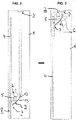
- Fig. 2 and Fig. 3 show in side view of an elevator shaft a schematic execution of the steps to be performed for the mounting of an elevator drive in the shaft head area by means of the mounting method according to the invention and the corresponding system. The sequence is indicated by the thick black arrow.
- Fig. 2 illustrates the preparations made in the method according to the invention.
- an elevator or counterweight guide rail string of elevator guide rails 4, on which the elevator drive 2 is to be mounted is set up.
- the second elevator guide rail for the counterweight or the car (depending on where the drive is to be fixed) has not yet been erected. This can be particularly useful in the case of narrow shafts. It is then possible to work as unhindered as possible in the shaft and, in particular, the elevator drive can then be raised largely freely.
- the mounting slide 7 is then mounted on the elevator guide rails 4.
- the elevator guide rails 4 are used to support the elevator drive 2 in its intended mounting position.
- the mounting slide is composed of two different assemblies.
- the counterweight 8 whereby this represents a complete frame construction (see Fig. 4 and Fig. 5 ).
- the mounting slide also comprises the mounting bracket 9, which preferably consists of two parallel steel or bent components 10 (see Fig. 4 and Fig. 5 ).
- This mounting bracket is attached to the counterweight, which itself has been movably mounted between the elevator guide rails 4. As one can see the mounting bracket protrudes - more than insignificantly, in most cases across the safety distance - into the shaft area in which the elevator car will travel later on.
- Fig. 4 again shows the various assemblies individually and Fig. 5 in the assembled state.
- the elevator drive 2 preferably comprises the motor, a traction sheave and the feet.
- the preparatory steps also include mounting the lifting device 3 in the area of the shaft head or on the shaft head ceiling, as also shown in Fig. 2 .
- the lifting device 3 must then be connected to the mounting slide 9.
- the lifting aid 13, which must be attached to the mounting bracket 9 beforehand, is preferably used for this purpose.
- the lifting aid 13 is then attached to the lifting device 3, usually to the load hook 12. Sometimes a lifting gear not shown in the figure is used for this purpose.
- the elevator drive 2 is then lifted up the shaft 1 until it reaches the position shown in Fig. 3 .
- This is the intended installation height.
- a temporary work platform 6 can be erected, at a height at which the worker can work ergonomically.
- the worker must move the elevator drive 2 or the assembly consisting of the elevator drive 2 and the drive base frame 5 into its intended mounting position (shown dashed in Fig. 3 ) essentially purely horizontally.
- the worker thus preferably carries out the assembly steps already mentioned for fixing to the elevator guide rails 4:
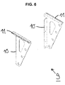
- Fig. 6 also shows the mounting bracket 9 of the system according to the invention. This consists of two bent components 10, each of which has the oblong hole 11 already mentioned.
Landscapes
- Lift-Guide Devices, And Elevator Ropes And Cables (AREA)
Applications Claiming Priority (1)
| Application Number | Priority Date | Filing Date | Title |
|---|---|---|---|
| DE102021105536 | 2021-03-08 |
Publications (1)
| Publication Number | Publication Date |
|---|---|
| EP4056514A1 true EP4056514A1 (fr) | 2022-09-14 |
Family
ID=80683939
Family Applications (1)
| Application Number | Title | Priority Date | Filing Date |
|---|---|---|---|
| EP22160857.3A Pending EP4056514A1 (fr) | 2021-03-08 | 2022-03-08 | Procédé de montage d'un entraînement d'ascenseur |
Country Status (1)
| Country | Link |
|---|---|
| EP (1) | EP4056514A1 (fr) |
Cited By (1)
| Publication number | Priority date | Publication date | Assignee | Title |
|---|---|---|---|---|
| EP4512761A1 (fr) * | 2023-08-22 | 2025-02-26 | TK Elevator Innovation and Operations GmbH | Procédé d'installation d'une unité d'entraînement d'un système d'ascenseur ainsi que système d'ascenseur correspondant et utilisation |
Citations (4)
| Publication number | Priority date | Publication date | Assignee | Title |
|---|---|---|---|---|
| JP2000034072A (ja) | 1998-07-17 | 2000-02-02 | Hitachi Building Systems Co Ltd | エレベータ巻上機の据付装置 |
| JP2012201497A (ja) * | 2011-03-28 | 2012-10-22 | Toshiba Elevator Co Ltd | マシンベッド及び揚重装置 |
| US10252889B2 (en) * | 2012-05-02 | 2019-04-09 | Otis Elevator Company | Method of installing a machine in an elevator system |
| US20200283271A1 (en) * | 2019-03-07 | 2020-09-10 | Thyssenkrupp Elevator Ag | Methods and apparatuses for installing elevator machines |
-
2022
- 2022-03-08 EP EP22160857.3A patent/EP4056514A1/fr active Pending
Patent Citations (4)
| Publication number | Priority date | Publication date | Assignee | Title |
|---|---|---|---|---|
| JP2000034072A (ja) | 1998-07-17 | 2000-02-02 | Hitachi Building Systems Co Ltd | エレベータ巻上機の据付装置 |
| JP2012201497A (ja) * | 2011-03-28 | 2012-10-22 | Toshiba Elevator Co Ltd | マシンベッド及び揚重装置 |
| US10252889B2 (en) * | 2012-05-02 | 2019-04-09 | Otis Elevator Company | Method of installing a machine in an elevator system |
| US20200283271A1 (en) * | 2019-03-07 | 2020-09-10 | Thyssenkrupp Elevator Ag | Methods and apparatuses for installing elevator machines |
Cited By (2)
| Publication number | Priority date | Publication date | Assignee | Title |
|---|---|---|---|---|
| EP4512761A1 (fr) * | 2023-08-22 | 2025-02-26 | TK Elevator Innovation and Operations GmbH | Procédé d'installation d'une unité d'entraînement d'un système d'ascenseur ainsi que système d'ascenseur correspondant et utilisation |
| DE102023122504A1 (de) * | 2023-08-22 | 2025-02-27 | Tk Elevator Innovation And Operations Gmbh | Verfahren zum Installieren einer Antriebseinheit einer Aufzuganlagenanordnung sowie entsprechende Aufzuganlagenanordnung und Verwendung |
Similar Documents
| Publication | Publication Date | Title |
|---|---|---|
| KR101226976B1 (ko) | 엘리베이터 기계 지지체 | |
| US11845638B2 (en) | Method for installing an elevator system | |
| EP2844600B1 (fr) | Procédé d'installation d'une machine dans un système d'ascenseur | |
| CN1962387B (zh) | 建造电梯设备的方法及用于该目的的电梯设备 | |
| KR101225035B1 (ko) | 엘리베이터 기계 지지체에 지지된 제어 전자기기를 포함한 엘리베이터 시스템 | |
| CN110526074A (zh) | 电梯的配重承接夹具以及配重承接夹具的安装方法 | |
| KR20070037995A (ko) | 승강실 및 승강로에 승강실의 지지 수단을 설치하는 방법 | |
| KR101216428B1 (ko) | 엘리베이터 시스템 및 설치 방법 | |
| EP4056514A1 (fr) | Procédé de montage d'un entraînement d'ascenseur | |
| US11834296B2 (en) | Machine room-less elevator construction | |
| US6364067B1 (en) | Method and apparatus for installing elevator components | |
| JPH09151053A (ja) | エレベータの乗かごの固定装置 | |
| JP2007210703A (ja) | マシンルームレスエレベータの巻上機据付装置および据付工法 | |
| US11059701B2 (en) | Methods and apparatuses for lifting elevator cars during installation | |
| JP5806166B2 (ja) | エレベータ改修用機器設置方法 | |
| JP4978218B2 (ja) | エレベータの据付装置及び据付方法 | |
| JP2001335255A (ja) | エレベーターの据付工法及びエレベーターの据付用ユニット | |
| KR20180101486A (ko) | 엘리베이터 장치 | |
| JP7583224B2 (ja) | 巻上機据付ガイド装置及び巻上機の据付方法 | |
| KR102591572B1 (ko) | 승강기 시스템으로 마련되는 균형추 설치용 리프트장치 | |
| HK40062751A (en) | Traction machine unit with mounting jig and mounting method thereof | |
| HK40098147A (zh) | 用於封闭电梯设备的电梯竪井的封顶模块和方法 | |
| CN114074883A (zh) | 具备安装夹具的曳引机单元以及其安装方法 | |
| JP2009155089A (ja) | ライズアップ工法によるエレベータ | |
| JP2008050159A (ja) | エレベータの錘保持装置および主ロープ緩和方法 |
Legal Events
| Date | Code | Title | Description |
|---|---|---|---|
| PUAI | Public reference made under article 153(3) epc to a published international application that has entered the european phase |
Free format text: ORIGINAL CODE: 0009012 |
|
| STAA | Information on the status of an ep patent application or granted ep patent |
Free format text: STATUS: THE APPLICATION HAS BEEN PUBLISHED |
|
| AK | Designated contracting states |
Kind code of ref document: A1 Designated state(s): AL AT BE BG CH CY CZ DE DK EE ES FI FR GB GR HR HU IE IS IT LI LT LU LV MC MK MT NL NO PL PT RO RS SE SI SK SM TR |
|
| STAA | Information on the status of an ep patent application or granted ep patent |
Free format text: STATUS: REQUEST FOR EXAMINATION WAS MADE |
|
| 17P | Request for examination filed |
Effective date: 20230314 |
|
| RBV | Designated contracting states (corrected) |
Designated state(s): AL AT BE BG CH CY CZ DE DK EE ES FI FR GB GR HR HU IE IS IT LI LT LU LV MC MK MT NL NO PL PT RO RS SE SI SK SM TR |