EP4056738A2 - Systèmes et procédés d'élimination de revêtement de diffusion à partir d'aubages - Google Patents
Systèmes et procédés d'élimination de revêtement de diffusion à partir d'aubages Download PDFInfo
- Publication number
- EP4056738A2 EP4056738A2 EP22159930.1A EP22159930A EP4056738A2 EP 4056738 A2 EP4056738 A2 EP 4056738A2 EP 22159930 A EP22159930 A EP 22159930A EP 4056738 A2 EP4056738 A2 EP 4056738A2
- Authority
- EP
- European Patent Office
- Prior art keywords
- gas turbine
- turbine engine
- engine component
- vol
- diffusion coating
- Prior art date
- Legal status (The legal status is an assumption and is not a legal conclusion. Google has not performed a legal analysis and makes no representation as to the accuracy of the status listed.)
- Withdrawn
Links
- 238000000576 coating method Methods 0.000 title claims abstract description 90
- 239000011248 coating agent Substances 0.000 title claims abstract description 86
- 238000009792 diffusion process Methods 0.000 title claims abstract description 75
- 238000000034 method Methods 0.000 title claims abstract description 53
- 239000000463 material Substances 0.000 claims abstract description 42
- 229910000951 Aluminide Inorganic materials 0.000 claims abstract description 39
- OKTJSMMVPCPJKN-UHFFFAOYSA-N Carbon Chemical compound [C] OKTJSMMVPCPJKN-UHFFFAOYSA-N 0.000 claims abstract description 38
- 239000002253 acid Substances 0.000 claims abstract description 38
- 239000010439 graphite Substances 0.000 claims abstract description 38
- 229910002804 graphite Inorganic materials 0.000 claims abstract description 38
- 230000004044 response Effects 0.000 claims abstract description 19
- XLYOFNOQVPJJNP-UHFFFAOYSA-N water Substances O XLYOFNOQVPJJNP-UHFFFAOYSA-N 0.000 claims abstract description 12
- 229910000990 Ni alloy Inorganic materials 0.000 claims abstract description 9
- GRYLNZFGIOXLOG-UHFFFAOYSA-N Nitric acid Chemical compound O[N+]([O-])=O GRYLNZFGIOXLOG-UHFFFAOYSA-N 0.000 claims description 29
- 229910017604 nitric acid Inorganic materials 0.000 claims description 29
- 238000006243 chemical reaction Methods 0.000 claims description 24
- PXHVJJICTQNCMI-UHFFFAOYSA-N Nickel Chemical compound [Ni] PXHVJJICTQNCMI-UHFFFAOYSA-N 0.000 claims description 8
- 238000006479 redox reaction Methods 0.000 claims description 6
- 229910000601 superalloy Inorganic materials 0.000 claims description 6
- 230000008878 coupling Effects 0.000 claims description 5
- 238000010168 coupling process Methods 0.000 claims description 5
- 238000005859 coupling reaction Methods 0.000 claims description 5
- 230000001965 increasing effect Effects 0.000 claims description 5
- 230000002708 enhancing effect Effects 0.000 claims description 4
- 229910052759 nickel Inorganic materials 0.000 claims description 4
- 238000010438 heat treatment Methods 0.000 claims description 3
- 230000003247 decreasing effect Effects 0.000 claims description 2
- 239000000243 solution Substances 0.000 description 52
- 239000007789 gas Substances 0.000 description 48
- 230000008569 process Effects 0.000 description 8
- 150000007513 acids Chemical class 0.000 description 7
- 230000008901 benefit Effects 0.000 description 6
- 239000011253 protective coating Substances 0.000 description 5
- 239000003929 acidic solution Substances 0.000 description 4
- 230000008439 repair process Effects 0.000 description 4
- 238000005070 sampling Methods 0.000 description 4
- QTBSBXVTEAMEQO-UHFFFAOYSA-N Acetic acid Chemical compound CC(O)=O QTBSBXVTEAMEQO-UHFFFAOYSA-N 0.000 description 3
- OFOBLEOULBTSOW-UHFFFAOYSA-N Malonic acid Chemical compound OC(=O)CC(O)=O OFOBLEOULBTSOW-UHFFFAOYSA-N 0.000 description 3
- MUBZPKHOEPUJKR-UHFFFAOYSA-N Oxalic acid Chemical compound OC(=O)C(O)=O MUBZPKHOEPUJKR-UHFFFAOYSA-N 0.000 description 3
- KRKNYBCHXYNGOX-UHFFFAOYSA-N citric acid Chemical compound OC(=O)CC(O)(C(O)=O)CC(O)=O KRKNYBCHXYNGOX-UHFFFAOYSA-N 0.000 description 3
- 150000007524 organic acids Chemical class 0.000 description 3
- 235000005985 organic acids Nutrition 0.000 description 3
- 230000002829 reductive effect Effects 0.000 description 3
- FERIUCNNQQJTOY-UHFFFAOYSA-N Butyric acid Chemical compound CCCC(O)=O FERIUCNNQQJTOY-UHFFFAOYSA-N 0.000 description 2
- VZCYOOQTPOCHFL-OWOJBTEDSA-N Fumaric acid Chemical compound OC(=O)\C=C\C(O)=O VZCYOOQTPOCHFL-OWOJBTEDSA-N 0.000 description 2
- VEXZGXHMUGYJMC-UHFFFAOYSA-N Hydrochloric acid Chemical compound Cl VEXZGXHMUGYJMC-UHFFFAOYSA-N 0.000 description 2
- NBIIXXVUZAFLBC-UHFFFAOYSA-N Phosphoric acid Chemical compound OP(O)(O)=O NBIIXXVUZAFLBC-UHFFFAOYSA-N 0.000 description 2
- LCTONWCANYUPML-UHFFFAOYSA-N Pyruvic acid Chemical compound CC(=O)C(O)=O LCTONWCANYUPML-UHFFFAOYSA-N 0.000 description 2
- NINIDFKCEFEMDL-UHFFFAOYSA-N Sulfur Chemical compound [S] NINIDFKCEFEMDL-UHFFFAOYSA-N 0.000 description 2
- QAOWNCQODCNURD-UHFFFAOYSA-N Sulfuric acid Chemical compound OS(O)(=O)=O QAOWNCQODCNURD-UHFFFAOYSA-N 0.000 description 2
- 239000005864 Sulphur Substances 0.000 description 2
- KKEYFWRCBNTPAC-UHFFFAOYSA-N Terephthalic acid Chemical compound OC(=O)C1=CC=C(C(O)=O)C=C1 KKEYFWRCBNTPAC-UHFFFAOYSA-N 0.000 description 2
- WNLRTRBMVRJNCN-UHFFFAOYSA-N adipic acid Chemical compound OC(=O)CCCCC(O)=O WNLRTRBMVRJNCN-UHFFFAOYSA-N 0.000 description 2
- MBMBGCFOFBJSGT-KUBAVDMBSA-N all-cis-docosa-4,7,10,13,16,19-hexaenoic acid Chemical compound CC\C=C/C\C=C/C\C=C/C\C=C/C\C=C/C\C=C/CCC(O)=O MBMBGCFOFBJSGT-KUBAVDMBSA-N 0.000 description 2
- 229910052782 aluminium Inorganic materials 0.000 description 2
- XAGFODPZIPBFFR-UHFFFAOYSA-N aluminium Chemical compound [Al] XAGFODPZIPBFFR-UHFFFAOYSA-N 0.000 description 2
- WPYMKLBDIGXBTP-UHFFFAOYSA-N benzoic acid Chemical compound OC(=O)C1=CC=CC=C1 WPYMKLBDIGXBTP-UHFFFAOYSA-N 0.000 description 2
- 238000002485 combustion reaction Methods 0.000 description 2
- XBDQKXXYIPTUBI-UHFFFAOYSA-N dimethylselenoniopropionate Natural products CCC(O)=O XBDQKXXYIPTUBI-UHFFFAOYSA-N 0.000 description 2
- POULHZVOKOAJMA-UHFFFAOYSA-N dodecanoic acid Chemical compound CCCCCCCCCCCC(O)=O POULHZVOKOAJMA-UHFFFAOYSA-N 0.000 description 2
- MNWFXJYAOYHMED-UHFFFAOYSA-N heptanoic acid Chemical compound CCCCCCC(O)=O MNWFXJYAOYHMED-UHFFFAOYSA-N 0.000 description 2
- 229910052500 inorganic mineral Inorganic materials 0.000 description 2
- QQVIHTHCMHWDBS-UHFFFAOYSA-N isophthalic acid Chemical compound OC(=O)C1=CC=CC(C(O)=O)=C1 QQVIHTHCMHWDBS-UHFFFAOYSA-N 0.000 description 2
- JVTAAEKCZFNVCJ-UHFFFAOYSA-N lactic acid Chemical compound CC(O)C(O)=O JVTAAEKCZFNVCJ-UHFFFAOYSA-N 0.000 description 2
- 238000004519 manufacturing process Methods 0.000 description 2
- BDAGIHXWWSANSR-UHFFFAOYSA-N methanoic acid Natural products OC=O BDAGIHXWWSANSR-UHFFFAOYSA-N 0.000 description 2
- 239000011707 mineral Substances 0.000 description 2
- 239000000203 mixture Substances 0.000 description 2
- TXXHDPDFNKHHGW-UHFFFAOYSA-N muconic acid Chemical compound OC(=O)C=CC=CC(O)=O TXXHDPDFNKHHGW-UHFFFAOYSA-N 0.000 description 2
- BDJRBEYXGGNYIS-UHFFFAOYSA-N nonanedioic acid Chemical compound OC(=O)CCCCCCCC(O)=O BDJRBEYXGGNYIS-UHFFFAOYSA-N 0.000 description 2
- FBUKVWPVBMHYJY-UHFFFAOYSA-N nonanoic acid Chemical compound CCCCCCCCC(O)=O FBUKVWPVBMHYJY-UHFFFAOYSA-N 0.000 description 2
- XNGIFLGASWRNHJ-UHFFFAOYSA-N phthalic acid Chemical compound OC(=O)C1=CC=CC=C1C(O)=O XNGIFLGASWRNHJ-UHFFFAOYSA-N 0.000 description 2
- WLJVNTCWHIRURA-UHFFFAOYSA-N pimelic acid Chemical compound OC(=O)CCCCCC(O)=O WLJVNTCWHIRURA-UHFFFAOYSA-N 0.000 description 2
- YGSDEFSMJLZEOE-UHFFFAOYSA-N salicylic acid Chemical compound OC(=O)C1=CC=CC=C1O YGSDEFSMJLZEOE-UHFFFAOYSA-N 0.000 description 2
- CXMXRPHRNRROMY-UHFFFAOYSA-N sebacic acid Chemical compound OC(=O)CCCCCCCCC(O)=O CXMXRPHRNRROMY-UHFFFAOYSA-N 0.000 description 2
- TYFQFVWCELRYAO-UHFFFAOYSA-N suberic acid Chemical compound OC(=O)CCCCCCC(O)=O TYFQFVWCELRYAO-UHFFFAOYSA-N 0.000 description 2
- 239000000126 substance Substances 0.000 description 2
- VZCYOOQTPOCHFL-UHFFFAOYSA-N trans-butenedioic acid Natural products OC(=O)C=CC(O)=O VZCYOOQTPOCHFL-UHFFFAOYSA-N 0.000 description 2
- NQPDZGIKBAWPEJ-UHFFFAOYSA-N valeric acid Chemical compound CCCCC(O)=O NQPDZGIKBAWPEJ-UHFFFAOYSA-N 0.000 description 2
- MHVJRKBZMUDEEV-APQLOABGSA-N (+)-Pimaric acid Chemical compound [C@H]1([C@](CCC2)(C)C(O)=O)[C@@]2(C)[C@H]2CC[C@](C=C)(C)C=C2CC1 MHVJRKBZMUDEEV-APQLOABGSA-N 0.000 description 1
- MHVJRKBZMUDEEV-UHFFFAOYSA-N (-)-ent-pimara-8(14),15-dien-19-oic acid Natural products C1CCC(C(O)=O)(C)C2C1(C)C1CCC(C=C)(C)C=C1CC2 MHVJRKBZMUDEEV-UHFFFAOYSA-N 0.000 description 1
- XVOUMQNXTGKGMA-OWOJBTEDSA-N (E)-glutaconic acid Chemical compound OC(=O)C\C=C\C(O)=O XVOUMQNXTGKGMA-OWOJBTEDSA-N 0.000 description 1
- BJEPYKJPYRNKOW-REOHCLBHSA-N (S)-malic acid Chemical compound OC(=O)[C@@H](O)CC(O)=O BJEPYKJPYRNKOW-REOHCLBHSA-N 0.000 description 1
- RTBFRGCFXZNCOE-UHFFFAOYSA-N 1-methylsulfonylpiperidin-4-one Chemical compound CS(=O)(=O)N1CCC(=O)CC1 RTBFRGCFXZNCOE-UHFFFAOYSA-N 0.000 description 1
- BTXXTMOWISPQSJ-UHFFFAOYSA-N 4,4,4-trifluorobutan-2-one Chemical compound CC(=O)CC(F)(F)F BTXXTMOWISPQSJ-UHFFFAOYSA-N 0.000 description 1
- OSWFIVFLDKOXQC-UHFFFAOYSA-N 4-(3-methoxyphenyl)aniline Chemical compound COC1=CC=CC(C=2C=CC(N)=CC=2)=C1 OSWFIVFLDKOXQC-UHFFFAOYSA-N 0.000 description 1
- 241000218642 Abies Species 0.000 description 1
- BQACOLQNOUYJCE-FYZZASKESA-N Abietic acid Natural products CC(C)C1=CC2=CC[C@]3(C)[C@](C)(CCC[C@@]3(C)C(=O)O)[C@H]2CC1 BQACOLQNOUYJCE-FYZZASKESA-N 0.000 description 1
- RSWGJHLUYNHPMX-UHFFFAOYSA-N Abietic-Saeure Natural products C12CCC(C(C)C)=CC2=CCC2C1(C)CCCC2(C)C(O)=O RSWGJHLUYNHPMX-UHFFFAOYSA-N 0.000 description 1
- WDJHALXBUFZDSR-UHFFFAOYSA-N Acetoacetic acid Natural products CC(=O)CC(O)=O WDJHALXBUFZDSR-UHFFFAOYSA-N 0.000 description 1
- 239000005711 Benzoic acid Substances 0.000 description 1
- 239000005639 Lauric acid Substances 0.000 description 1
- TXXHDPDFNKHHGW-CCAGOZQPSA-N Muconic acid Natural products OC(=O)\C=C/C=C\C(O)=O TXXHDPDFNKHHGW-CCAGOZQPSA-N 0.000 description 1
- 229910018487 Ni—Cr Inorganic materials 0.000 description 1
- 239000005643 Pelargonic acid Substances 0.000 description 1
- KDYFGRWQOYBRFD-UHFFFAOYSA-N Succinic acid Natural products OC(=O)CCC(O)=O KDYFGRWQOYBRFD-UHFFFAOYSA-N 0.000 description 1
- 235000011054 acetic acid Nutrition 0.000 description 1
- 239000000654 additive Substances 0.000 description 1
- 230000000996 additive effect Effects 0.000 description 1
- 239000001361 adipic acid Substances 0.000 description 1
- 235000011037 adipic acid Nutrition 0.000 description 1
- JAZBEHYOTPTENJ-JLNKQSITSA-N all-cis-5,8,11,14,17-icosapentaenoic acid Chemical compound CC\C=C/C\C=C/C\C=C/C\C=C/C\C=C/CCCC(O)=O JAZBEHYOTPTENJ-JLNKQSITSA-N 0.000 description 1
- 229910045601 alloy Inorganic materials 0.000 description 1
- 239000000956 alloy Substances 0.000 description 1
- BJEPYKJPYRNKOW-UHFFFAOYSA-N alpha-hydroxysuccinic acid Natural products OC(=O)C(O)CC(O)=O BJEPYKJPYRNKOW-UHFFFAOYSA-N 0.000 description 1
- 229910000147 aluminium phosphate Inorganic materials 0.000 description 1
- JFCQEDHGNNZCLN-UHFFFAOYSA-N anhydrous glutaric acid Natural products OC(=O)CCCC(O)=O JFCQEDHGNNZCLN-UHFFFAOYSA-N 0.000 description 1
- 235000010233 benzoic acid Nutrition 0.000 description 1
- KDYFGRWQOYBRFD-NUQCWPJISA-N butanedioic acid Chemical compound O[14C](=O)CC[14C](O)=O KDYFGRWQOYBRFD-NUQCWPJISA-N 0.000 description 1
- BVKZGUZCCUSVTD-UHFFFAOYSA-N carbonic acid Chemical compound OC(O)=O BVKZGUZCCUSVTD-UHFFFAOYSA-N 0.000 description 1
- VNNRSPGTAMTISX-UHFFFAOYSA-N chromium nickel Chemical compound [Cr].[Ni] VNNRSPGTAMTISX-UHFFFAOYSA-N 0.000 description 1
- 229910017052 cobalt Inorganic materials 0.000 description 1
- 239000010941 cobalt Substances 0.000 description 1
- GUTLYIVDDKVIGB-UHFFFAOYSA-N cobalt atom Chemical compound [Co] GUTLYIVDDKVIGB-UHFFFAOYSA-N 0.000 description 1
- 239000000567 combustion gas Substances 0.000 description 1
- 238000001816 cooling Methods 0.000 description 1
- 239000012809 cooling fluid Substances 0.000 description 1
- 238000005260 corrosion Methods 0.000 description 1
- 230000007797 corrosion Effects 0.000 description 1
- -1 di-carboxylic acids Chemical class 0.000 description 1
- WOWBFOBYOAGEEA-UHFFFAOYSA-N diafenthiuron Chemical compound CC(C)C1=C(NC(=S)NC(C)(C)C)C(C(C)C)=CC(OC=2C=CC=CC=2)=C1 WOWBFOBYOAGEEA-UHFFFAOYSA-N 0.000 description 1
- 239000012895 dilution Substances 0.000 description 1
- 238000010790 dilution Methods 0.000 description 1
- 235000020669 docosahexaenoic acid Nutrition 0.000 description 1
- 229940090949 docosahexaenoic acid Drugs 0.000 description 1
- 230000000694 effects Effects 0.000 description 1
- JAZBEHYOTPTENJ-UHFFFAOYSA-N eicosapentaenoic acid Natural products CCC=CCC=CCC=CCC=CCC=CCCCC(O)=O JAZBEHYOTPTENJ-UHFFFAOYSA-N 0.000 description 1
- 235000020673 eicosapentaenoic acid Nutrition 0.000 description 1
- 229960005135 eicosapentaenoic acid Drugs 0.000 description 1
- 230000003628 erosive effect Effects 0.000 description 1
- 235000019253 formic acid Nutrition 0.000 description 1
- 239000000446 fuel Substances 0.000 description 1
- 239000001530 fumaric acid Substances 0.000 description 1
- 229910001026 inconel Inorganic materials 0.000 description 1
- 239000004310 lactic acid Substances 0.000 description 1
- 235000014655 lactic acid Nutrition 0.000 description 1
- 229940033355 lauric acid Drugs 0.000 description 1
- VZCYOOQTPOCHFL-UPHRSURJSA-N maleic acid Chemical compound OC(=O)\C=C/C(O)=O VZCYOOQTPOCHFL-UPHRSURJSA-N 0.000 description 1
- 239000011976 maleic acid Substances 0.000 description 1
- 239000001630 malic acid Substances 0.000 description 1
- 235000011090 malic acid Nutrition 0.000 description 1
- 229910052751 metal Inorganic materials 0.000 description 1
- 239000002184 metal Substances 0.000 description 1
- 150000002739 metals Chemical class 0.000 description 1
- 150000007522 mineralic acids Chemical class 0.000 description 1
- 150000002763 monocarboxylic acids Chemical class 0.000 description 1
- 235000006408 oxalic acid Nutrition 0.000 description 1
- 230000003647 oxidation Effects 0.000 description 1
- 238000007254 oxidation reaction Methods 0.000 description 1
- FJKROLUGYXJWQN-UHFFFAOYSA-N papa-hydroxy-benzoic acid Natural products OC(=O)C1=CC=C(O)C=C1 FJKROLUGYXJWQN-UHFFFAOYSA-N 0.000 description 1
- 230000036961 partial effect Effects 0.000 description 1
- 235000019260 propionic acid Nutrition 0.000 description 1
- 229940107700 pyruvic acid Drugs 0.000 description 1
- IUVKMZGDUIUOCP-BTNSXGMBSA-N quinbolone Chemical compound O([C@H]1CC[C@H]2[C@H]3[C@@H]([C@]4(C=CC(=O)C=C4CC3)C)CC[C@@]21C)C1=CCCC1 IUVKMZGDUIUOCP-BTNSXGMBSA-N 0.000 description 1
- 229960004889 salicylic acid Drugs 0.000 description 1
- 229920006395 saturated elastomer Polymers 0.000 description 1
- 230000003068 static effect Effects 0.000 description 1
- MAZWDMBCPDUFDJ-UHFFFAOYSA-N trans-Traumatinsaeure Natural products OC(=O)CCCCCCCCC=CC(O)=O MAZWDMBCPDUFDJ-UHFFFAOYSA-N 0.000 description 1
- MAZWDMBCPDUFDJ-VQHVLOKHSA-N traumatic acid Chemical compound OC(=O)CCCCCCCC\C=C\C(O)=O MAZWDMBCPDUFDJ-VQHVLOKHSA-N 0.000 description 1
- 150000003628 tricarboxylic acids Chemical class 0.000 description 1
- 229940005605 valeric acid Drugs 0.000 description 1
Images

Classifications
-
- C—CHEMISTRY; METALLURGY
- C25—ELECTROLYTIC OR ELECTROPHORETIC PROCESSES; APPARATUS THEREFOR
- C25F—PROCESSES FOR THE ELECTROLYTIC REMOVAL OF MATERIALS FROM OBJECTS; APPARATUS THEREFOR
- C25F5/00—Electrolytic stripping of metallic layers or coatings
-
- C—CHEMISTRY; METALLURGY
- C25—ELECTROLYTIC OR ELECTROPHORETIC PROCESSES; APPARATUS THEREFOR
- C25F—PROCESSES FOR THE ELECTROLYTIC REMOVAL OF MATERIALS FROM OBJECTS; APPARATUS THEREFOR
- C25F3/00—Electrolytic etching or polishing
- C25F3/02—Etching
-
- C—CHEMISTRY; METALLURGY
- C23—COATING METALLIC MATERIAL; COATING MATERIAL WITH METALLIC MATERIAL; CHEMICAL SURFACE TREATMENT; DIFFUSION TREATMENT OF METALLIC MATERIAL; COATING BY VACUUM EVAPORATION, BY SPUTTERING, BY ION IMPLANTATION OR BY CHEMICAL VAPOUR DEPOSITION, IN GENERAL; INHIBITING CORROSION OF METALLIC MATERIAL OR INCRUSTATION IN GENERAL
- C23C—COATING METALLIC MATERIAL; COATING MATERIAL WITH METALLIC MATERIAL; SURFACE TREATMENT OF METALLIC MATERIAL BY DIFFUSION INTO THE SURFACE, BY CHEMICAL CONVERSION OR SUBSTITUTION; COATING BY VACUUM EVAPORATION, BY SPUTTERING, BY ION IMPLANTATION OR BY CHEMICAL VAPOUR DEPOSITION, IN GENERAL
- C23C10/00—Solid state diffusion of only metal elements or silicon into metallic material surfaces
- C23C10/60—After-treatment
-
- C—CHEMISTRY; METALLURGY
- C25—ELECTROLYTIC OR ELECTROPHORETIC PROCESSES; APPARATUS THEREFOR
- C25F—PROCESSES FOR THE ELECTROLYTIC REMOVAL OF MATERIALS FROM OBJECTS; APPARATUS THEREFOR
- C25F7/00—Constructional parts, or assemblies thereof, of cells for electrolytic removal of material from objects; Servicing or operating
-
- C—CHEMISTRY; METALLURGY
- C23—COATING METALLIC MATERIAL; COATING MATERIAL WITH METALLIC MATERIAL; CHEMICAL SURFACE TREATMENT; DIFFUSION TREATMENT OF METALLIC MATERIAL; COATING BY VACUUM EVAPORATION, BY SPUTTERING, BY ION IMPLANTATION OR BY CHEMICAL VAPOUR DEPOSITION, IN GENERAL; INHIBITING CORROSION OF METALLIC MATERIAL OR INCRUSTATION IN GENERAL
- C23F—NON-MECHANICAL REMOVAL OF METALLIC MATERIAL FROM SURFACE; INHIBITING CORROSION OF METALLIC MATERIAL OR INCRUSTATION IN GENERAL; MULTI-STEP PROCESSES FOR SURFACE TREATMENT OF METALLIC MATERIAL INVOLVING AT LEAST ONE PROCESS PROVIDED FOR IN CLASS C23 AND AT LEAST ONE PROCESS COVERED BY SUBCLASS C21D OR C22F OR CLASS C25
- C23F1/00—Etching metallic material by chemical means
- C23F1/44—Compositions for etching metallic material from a metallic material substrate of different composition
Definitions
- the disclosure relates generally to airfoils in gas turbine engines and systems and methods for removing diffusion coatings from airfoils of gas turbine engines.
- Removal of diffusion coatings from gas turbine engine airfoils may be performed during a repair process or during a manufacturing process for various reasons.
- an airfoil may not meet a desired geometric dimension(s) and tolerancing for a respective application with an original diffusion coating, so the diffusion coating may be removed and re-applied to meet the desired specification of the airfoil.
- an airfoil may be removed from service after a specified time on wing of an aircraft.
- a diffusion coating may be removed, the airfoil restored, and a new diffusion coating re-applied prior to returning the airfoil to service.
- Typical systems and methods for removing a diffusion coating from an airfoil include a high-temperature concentrated acid solution with heavy capital equipment investments. Additionally, typical systems and methods are susceptible to damaging the airfoil resulting in significant costs when an airfoil is scrapped due to excess removal of the component's base material.
- a method of removing an aluminide diffusion coating from a gas turbine engine component having a nickel alloy base material is disclosed herein.
- the method may comprise: disposing the gas turbine engine component in a solution, the solution including an acid between 5% and 15% vol./vol. and water between 85% and 95% vol./vol.; placing the gas turbine engine component in electrical contact with a graphite plate; and removing the aluminide diffusion coating from the gas turbine engine component in response to placing the gas turbine engine component in electrical contact with the graphite plate and disposing the gas turbine engine component in the solution.
- the method may further comprise increasing a reaction rate of the solution in response to generating a voltage differential between the solution and the aluminide diffusion coating.
- the method may further comprise reducing the reaction rate in response to the aluminide diffusion coating being removed and the solution contacting the nickel alloy base material.
- the method may further comprise heating the solution between 80 °F (27 °C) and 140 °F (60 °C).
- the gas turbine engine component may include an airfoil.
- the method may further comprise placing the gas turbine engine component in direct contact with the graphite plate.
- the method may further comprise electrically coupling the gas turbine engine component is electrically coupled to the graphite plate.
- the acid may be a nitric acid.
- a method of removing an aluminide diffusion coating from a gas turbine engine component having a nickel alloy base material via a coating removal system is disclosed herein.
- the method may comprise: enhancing, via the coating removal system, a reaction rate of a diluted acid solution in response to generating a localized redox reaction between the aluminide diffusion coating and the diluted acid solution; removing, via the coating removal system, the aluminide diffusion coating from the nickel alloy base material in response to generating the localized redox reaction; and reducing, via the coating removal system, the reaction rate of the diluted acid solution in response to the aluminide diffusion coating being removed.
- a first electromotive force produced during the enhancing the reaction rate of the diluted acid solution is greater than a second electromotive force produce during reducing the reaction rate of the diluted acid solution.
- the diluted acid solution may be an acid between 5% and 15% vol./vol. and water between 85% and 95% vol./vol.
- the diluted acid may be a solution with a temperature between 80 °F (27 °C) and 140 °F (60 °C).
- the acid may be nitric acid.
- the coating removal system may include a graphite plate in electrical communication with the gas turbine engine component. The graphite plate may be disposed in the diluted acid solution.
- a system for removing an aluminide diffusion coating may comprise: a diluted nitric acid solution comprising nitric acid between 5% and 15% vol./vol. and water between 85% and 95% vol./vol; and a graphite plate disposed in the diluted nitric acid solution, the graphite plate configured to be in electrical communication with a gas turbine engine component during removal of the aluminide diffusion coating.
- the system may further comprise a heater, wherein the heater is configured to heat the diluted nitric acid solution to a temperature between 80 °F (27 °C) and 140 °F (60 °C).
- the system may further comprise the gas turbine engine component disposed in the diluted nitric acid solution, the gas turbine engine component comprising a base material and the aluminide diffusion coating, the base material comprising a nickel-based superalloy.
- a reaction rate of the diluted nitric acid solution may be increased in response to an electromotive force generated from a voltage differential between the diluted nitric acid solution and the aluminide diffusion coating.
- the reaction rate of the diluted nitric acid solution may be decreased in response to the aluminide diffusion coating being removed.
- aluminide diffusion coating removal systems and methods are disclosed herein.
- the systems and methods correspond to removal of an aluminide diffusion coating from a nickel-base, or cobalt-base, superalloy.
- the methods and systems disclosed herein may reduce capital intensive equipment for diffusion coating removal, mitigate air permits, water sampling, outfall samplings, emissions, and discharge exposure to concentrated acids for diffusion coating removal, reduce an amount of base material removed from a gas turbine engine component during diffusion coating removal, enhance a life of a restored gas turbine engine component, and/or reduce a cost of the removal methods and system.
- Gas turbine engine 100 (such as a turbofan gas turbine engine) is illustrated according to various embodiments.
- Gas turbine engine 100 is disposed about axial centerline axis 120, which may also be referred to as axis of rotation 120.
- Gas turbine engine 100 may comprise a fan 140, compressor sections 150 and 160, a combustion section 180, and a turbine section 190. Air compressed in the compressor sections 150, 160 may be mixed with fuel and burned in combustion section 180 and expanded across turbine section 190.
- Turbine section 190 may include high pressure rotors 192 and low pressure rotors 194, which rotate in response to the expansion.
- Turbine section 190 may comprise alternating rows of rotary airfoils or blades 196 and static airfoils or vanes 198.
- a plurality of bearings 115 may support spools in the gas turbine engine 100.
- Any parts in gas turbine engine 100 may comprise a metallic diffusion or overlay coating to improve high temperature performance.
- high pressure rotors 192, low pressure rotors 194, blades 196, or vanes 198 may be coated with an aluminum-based overlay or diffusion coating.
- FIG. 1 provides a general understanding of the sections in a gas turbine engine and is not intended to limit the disclosure. The present disclosure may extend to all types of turbine engines, including turbofan gas turbine engines and turbojet engines, for all types of applications
- Gas turbine engine components such as high pressure rotors 192, low pressure rotors 194, blades 196, or vanes 198 may be manufactured with a protective coating disposed thereon.
- the protective coating is an aluminized diffusion coating. After an extended time on wing, a protective coating as disclosed herein may degrade to a point where the protective coating provides reduced protection to an airfoil of the gas turbine engine component. Thus, during a repair process, any remainder of the protective coating may be removed, and the gas turbine engine component may be re-coated.
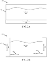
- the system includes a tank 202, a graphite plate 204, and a solution 206.
- the graphite plate 204 and the solution 206 are both disposed in the tank 202.
- the graphite plate 204 is a low Sulphur graphite plate (e.g., container Sulphur of less than 550 ppm).
- the graphite plate 204 may be configured to be electrically coupled (i.e., either directly, or indirectly through a conductive path as discussed further herein) to a base material of a gas turbine engine component (e.g., high pressure rotors 192, low pressure rotors 194, blades 196, or vanes 198 from FIG. 1 ) having an aluminide diffusion coating disposed thereon.
- a graphite plate 204 may be disposed proximate a bottom of tank 202 and be configured to receive a base material of a gas turbine engine component placed directly thereon.
- system 250 for removing a diffusion coating may comprise graphite plates 208, 210 placed on sides of a tank 202 with electrical wires 212, 214 configured to electrically couple the graphite plates 208, 210 to a respective base material of a gas turbine engine component, in accordance with various embodiments.
- An aluminide diffusion coating removal system may comprise solution 206 which is a highly diluted acidic solution comprising an acid diluted in water (e.g., between 5-15 % vol./vol. total acid), in accordance with various embodiments.
- the acid base may include, but are not limited to, one or more organic acids of any molecular weight, one or more mineral acids (inorganic acids), and mixtures thereof.
- Organic acids may include mono-carboxylic acids, di-carboxylic acids, or tri-carboxylic acids, and may be saturated or may have any degree of unsaturation.
- organic acids for use in various embodiments of the composition in accordance to the present disclosure may include, but are not limited to, formic acid, carbonic acid, acetic acid, lactic acid, oxalic acid, propionic acid, valeric acid, enanthic acid, pelargonic acid, butyric acid, lauric acid, docosahexaenoic acid, eicosapentaenoic acid, pyruvic acid, acetoacetic acid, benzoic acid, salicylic acid, aldaric acid, fumaric acid, glutaconic acid, traumatic acid, muconic acid, malonic acid, malic acid, succinic acid, glutaric acid, adipic acid, pimelic acid, suberic acid, azelaic acid, abietic acid, pimaric acid, sebacic acid, phthalic acid, isophthalic acid, terephthalic acid, maleic acid, citric acid, and combinations thereof.
- mineral acids for use in various embodiments of the solution in accordance to the present disclosure may include, but are not limited to hydrochloric acid, phosphoric acid, sulfuric acid, nitric acid, and combinations thereof.
- nitric acid is used as the only acid for the solution disclosed herein for base material (e.g., for high pressure rotors 192, low pressure rotors 194, blades 196, or vanes 198 from FIG. 1 ) having a nickel-base or cobalt-base superalloy.
- the solution 206 comprises between 5 % and 15 % vol./vol. nitric acid with a remainder vol./vol. being water.
- the total acidity may be significantly less than typical aluminide diffusion coating removal systems.
- total acidity of typical systems may typically range from around 30% vol./vol. to 50 % vol./vol.
- typical concentrated acids are used in the 30% vol./vol. to 50% vol./vol. range, after the diffusion coating is stripped off, the solution may begin to attack the base material.
- typical concentrated acids are susceptible to removal of too much base material, especially for a thin walled gas turbine component, or the like, which may result in a gas turbine component having to be scrapped.
- a reaction rate for removing a diffusion coating may be maintained or increased resulting in more consistent removal at a reduced cost.
- the solution 206 of system 200 may be a heated solution.
- the solution 206 may be heated to a temperature between 80 °F (27 °C) and 140 °F (60 °C), or between 95 °F (35 °C) and 140 °F (60 °C), or between 110 °F (43 °C) and 140 °F (60 °C).
- a lowering of an acidic solution by 10 ° F (6 °C) may result in a doubling of a reaction rate (i.e., removal of the diffusion coating would be substantially longer for every 10 °F (6 °C) the temperature is lowered relative to a typical removal solution).
- typical heated solutions for removal of aluminide diffusion coatings are in excess of 160 °F (71 °C) to main a sufficient reaction rate.
- a reaction rate at or above typical reaction rates of acidic solutions heated above 160 °F (71 °C) for removal of aluminide diffusion coatings may be maintained, and/or exceeded.
- the methods disclosed herein may reduce removal of the base material during the removal process, reduce a cost of the removal process, mitigate air permits, water sampling, outfall sampling, emissions, and/or discharge exposures to concentrated acids, or the like, in accordance with various embodiments.
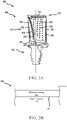
- an airfoil element 300 is illustrated schematically in the form of a rotor blade 306 from a turbine section, such as, for example, one of high pressure rotors 192 or low pressure rotors 194 from FIG. 1 .
- the rotor blade 306 includes an airfoil section 310, a root section 312 ( e.g ., a firtree root) and a blade tip 314.
- a platform 316 may be disposed between the airfoil section 310 and the root section 312.
- the airfoil section 310 typically extends in a spanwise direction between the platform 316 and the blade tip 314 and in a chordwise direction between a leading edge 318 and a trailing edge 320.
- the airfoil section 310 typically defines a pressure side surface 322 and a suction side surface 324.
- the rotor blade 306 includes an internal cooling passage system that includes a plurality of leading edge outlets 326, a plurality of trailing edge outlets 328, a plurality of pressure side surface outlets 330, a plurality of suction side surface outlets 332 and a plurality of blade tip outlets 334.
- the various pluralities of outlets provide openings for a cooling fluid circulating through various internal passageways within the rotor blade 306 to exit.
- airfoil element 300 includes a base material 350 and a diffusion coating 360.
- the base material 350 may comprise a nickel-based superalloy (e.g., an austenitic nickel-chromium-based alloy such as that sold under the trademark Inconel ® which is available from Special Metals Corporation of New Hartford, New York, USA), a cobalt-based superalloy, or the like.
- the diffusion coating 360 may comprise an aluminide diffusion coating. In various embodiments, the diffusion coating 360 may include a diffusion layer and an additive layer.
- the diffusion coating 360 is disposed on an external surface 352 of the base material 350.
- the diffusion coating 360 is configured to protect the base material 350 from the environment of the base material 350 during gas turbine engine operation. For example, during operation of the gas turbine engine 100 from FIG. 1 , hot combustion gases may be directed by the airfoil element 300 and subjected to severe attack by oxidation corrosion and erosion. In various embodiments, the diffusion coating 360 protects against these events and may erode overtime.
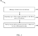
- the method 400 comprises heating a diluted nitric acid solution to a predetermined temperature (step 402).
- the diluted nitric acid solution may be in accordance with the solution 206 from FIGs. 2A-2B .
- the diluted nitric acid solution may contain between 5% and 15 % vol./vol. nitric acid and between 85% and 95% vol./vol. water.
- the diluted nitric acid solution may be significantly more diluted relative to typical diffusion coating removal processes.
- the predetermined temperature is between 80 °F (27 °C) and 140 °F (60 °C), or between 95 °F (35 °C) and 140 °F (60 °C), or between 110 °F (43 °C) and 140 °F (60 °C).
- the method 400 further comprises disposing a gas turbine engine component in the diluted nitric acid solution (step 404) and placing the gas turbine engine component in electrical contact with a graphite plate (step 406).
- the gas turbine engine component may be in accordance with airfoil element 300 from FIGs. 3A and 3B .
- the graphite plate is disposed in a tank in accordance with system 200 or system 250 from FIGs. 2A and 2B .
- the graphite plate is placed in electrical contact with the base material of the gas turbine engine component.
- the graphite plate is place in electrical contact.
- a localized redox reaction occurs allowing for the chemical stripping of the aluminide diffusion coating in the heated solution from step 402.
- the combination of the graphite plate 204 from FIGs. 2A-B , the base material (e.g., base material 350 from FIG. 3B ), the diffusion coating (e.g., diffusion coating 360 from FIG. 3B ), and the heated solution (e.g., solution 206 from FIGs. 2A-B ) essentially create an electrical circuit.
- a voltage differential may be generated between the graphite plate and the coating that is significantly greater than a voltage created between the graphite plate and the base material.
- the voltage created by electrically coupling the graphite plate to the gas turbine engine component essentially increases the reaction rate of the solution with respect to the coating and returns to a negligible, or nearly negligible effect once the coating is removed.
- the graphite plate may act as an electrical contact point for the system that allows the redox reaction to take place.
- a reaction rate of the solution towards the diffusion coating may be enhanced based on a voltage created due to the differential material (namely the aluminum in the coating and the nickel in the base material). Additionally, once the coating is removed, the voltage may become negligible and return the solution to a significantly lower reaction rate without the voltage differential.
- the systems and methods disclosed herein may be configured to prevent additional base material from being removed during a diffusion coating removal process, in accordance with various embodiments. This may allow for gas turbine engine components with thinner walls to utilize the removal process without a high risk of creating a component that has to be scrapped due to not meeting specifications.
- references to “one embodiment”, “an embodiment”, “an example embodiment”, etc. indicate that the embodiment described may include a particular feature, structure, or characteristic, but every embodiment may not necessarily include the particular feature, structure, or characteristic. Moreover, such phrases are not necessarily referring to the same embodiment. Further, when a particular feature, structure, or characteristic is described in connection with an embodiment, it is submitted that it is within the knowledge of one skilled in the art to affect such feature, structure, or characteristic in connection with other embodiments whether or not explicitly described. After reading the description, it will be apparent to one skilled in the relevant art(s) how to implement the disclosure in alternative embodiment
Landscapes
- Chemical & Material Sciences (AREA)
- Chemical Kinetics & Catalysis (AREA)
- Engineering & Computer Science (AREA)
- Materials Engineering (AREA)
- Metallurgy (AREA)
- Organic Chemistry (AREA)
- Electrochemistry (AREA)
- Mechanical Engineering (AREA)
- Turbine Rotor Nozzle Sealing (AREA)
Applications Claiming Priority (1)
| Application Number | Priority Date | Filing Date | Title |
|---|---|---|---|
| US17/200,429 US20220290322A1 (en) | 2021-03-12 | 2021-03-12 | Systems, formulations, and methods for removal of diffusion coating from airfoils |
Publications (2)
| Publication Number | Publication Date |
|---|---|
| EP4056738A2 true EP4056738A2 (fr) | 2022-09-14 |
| EP4056738A3 EP4056738A3 (fr) | 2022-12-21 |
Family
ID=80625271
Family Applications (1)
| Application Number | Title | Priority Date | Filing Date |
|---|---|---|---|
| EP22159930.1A Withdrawn EP4056738A3 (fr) | 2021-03-12 | 2022-03-03 | Systèmes et procédés d'élimination de revêtement de diffusion à partir d'aubages |
Country Status (2)
| Country | Link |
|---|---|
| US (1) | US20220290322A1 (fr) |
| EP (1) | EP4056738A3 (fr) |
Family Cites Families (6)
| Publication number | Priority date | Publication date | Assignee | Title |
|---|---|---|---|---|
| US4886552A (en) * | 1988-09-09 | 1989-12-12 | United Technologies Corporation | Method for monitoring the removal of a metallic contaminant from the surface of a metallic article |
| US6176999B1 (en) * | 1998-12-18 | 2001-01-23 | United Technologies Corporation | Feedback controlled stripping of airfoils |
| US6355116B1 (en) * | 2000-03-24 | 2002-03-12 | General Electric Company | Method for renewing diffusion coatings on superalloy substrates |
| US8377324B2 (en) * | 2005-06-10 | 2013-02-19 | Acromet Technologies Inc. | Methods for removing coatings from a metal component |
| EP2166125A1 (fr) * | 2008-09-19 | 2010-03-24 | ALSTOM Technology Ltd | Procédé pour la configuration des services d'un réseau personnel |
| CN103088399B (zh) * | 2011-10-31 | 2016-01-06 | 通用电气公司 | 多步骤电化学去金属涂层方法 |
-
2021
- 2021-03-12 US US17/200,429 patent/US20220290322A1/en not_active Abandoned
-
2022
- 2022-03-03 EP EP22159930.1A patent/EP4056738A3/fr not_active Withdrawn
Also Published As
| Publication number | Publication date |
|---|---|
| EP4056738A3 (fr) | 2022-12-21 |
| US20220290322A1 (en) | 2022-09-15 |
Similar Documents
| Publication | Publication Date | Title |
|---|---|---|
| US7824510B2 (en) | Methods of repairing engine components | |
| EP1880793A2 (fr) | Réparation de l'extrémité d'une aube de turbine à haute pression simple avec placage laser | |
| US8047771B2 (en) | Turbine nozzles and methods of manufacturing the same | |
| US7731809B2 (en) | Activated diffusion brazing alloys and repair process | |
| CA2647767C (fr) | Methode de reparation d'un segment de distributeur de turbine | |
| JP2006177363A (ja) | 補修翼端の再コーティングを行わないガスタービン翼端の補修方法 | |
| JP2010126812A (ja) | Tbc被覆タービン構成部品のための補修方法 | |
| CN110462170B (zh) | 具有涂层的法兰螺栓孔及其形成方法 | |
| JP2017020501A (ja) | タービンブレード補修のためのシステム及び方法 | |
| BR0101152B1 (pt) | método para remoção controlada de pelo menos uma parte de uma espessura de um revestimento de alumineto aditivo a partir de um substrato de superliga revestido. | |
| US20100008816A1 (en) | Nickel-based superalloys, repaired turbine engine components, and methods for repairing turbine components | |
| CN103382544A (zh) | 用于移除涂层的方法和用于修复涂层超合金构件的方法 | |
| US7699944B2 (en) | Intermetallic braze alloys and methods of repairing engine components | |
| EP2159371B1 (fr) | Ensemble aubes de turbine à gaz et procédés de réparation | |
| US20120084980A1 (en) | Extending Useful Life of a Cobalt-Based Gas Turbine Component | |
| JP4236919B2 (ja) | アルミニウム化合物拡散コーティングを修復するための方法 | |
| US20100279148A1 (en) | Nickel-based alloys and turbine components | |
| EP4056738A2 (fr) | Systèmes et procédés d'élimination de revêtement de diffusion à partir d'aubages | |
| Brauny et al. | Repair of air–cooled turbine vanes of high–performance aircraft engines–problems and experience | |
| JP2012112290A (ja) | ガスタービンの高温部品の損傷補修方法およびガスタービンの高温部品 | |
| NL2002340C2 (en) | Method for repairing a cooled turbine nozzle segment. | |
| EP3054028A1 (fr) | Réparation à chaud d'une section de revêtements métalliques | |
| EP3563967A1 (fr) | Décapage laser liquide amélioré | |
| CN117004845A (zh) | 镍基超级合金和部件 | |
| BRPI0405191B1 (pt) | Method of repair of an original received component of a gas turbine engine |
Legal Events
| Date | Code | Title | Description |
|---|---|---|---|
| PUAI | Public reference made under article 153(3) epc to a published international application that has entered the european phase |
Free format text: ORIGINAL CODE: 0009012 |
|
| STAA | Information on the status of an ep patent application or granted ep patent |
Free format text: STATUS: THE APPLICATION HAS BEEN PUBLISHED |
|
| AK | Designated contracting states |
Kind code of ref document: A2 Designated state(s): AL AT BE BG CH CY CZ DE DK EE ES FI FR GB GR HR HU IE IS IT LI LT LU LV MC MK MT NL NO PL PT RO RS SE SI SK SM TR |
|
| PUAL | Search report despatched |
Free format text: ORIGINAL CODE: 0009013 |
|
| AK | Designated contracting states |
Kind code of ref document: A3 Designated state(s): AL AT BE BG CH CY CZ DE DK EE ES FI FR GB GR HR HU IE IS IT LI LT LU LV MC MK MT NL NO PL PT RO RS SE SI SK SM TR |
|
| RIC1 | Information provided on ipc code assigned before grant |
Ipc: C23F 1/44 20060101ALI20221115BHEP Ipc: C23F 1/08 20060101ALI20221115BHEP Ipc: C23C 10/60 20060101ALI20221115BHEP Ipc: C25F 5/00 20060101AFI20221115BHEP |
|
| STAA | Information on the status of an ep patent application or granted ep patent |
Free format text: STATUS: THE APPLICATION IS DEEMED TO BE WITHDRAWN |
|
| 18D | Application deemed to be withdrawn |
Effective date: 20230622 |