EP4056744A1 - Système de broderie et agencement de métier à broder - Google Patents
Système de broderie et agencement de métier à broder Download PDFInfo
- Publication number
- EP4056744A1 EP4056744A1 EP21175926.1A EP21175926A EP4056744A1 EP 4056744 A1 EP4056744 A1 EP 4056744A1 EP 21175926 A EP21175926 A EP 21175926A EP 4056744 A1 EP4056744 A1 EP 4056744A1
- Authority
- EP
- European Patent Office
- Prior art keywords
- frame
- embroidery
- bridge
- connecting means
- fabric
- Prior art date
- Legal status (The legal status is an assumption and is not a legal conclusion. Google has not performed a legal analysis and makes no representation as to the accuracy of the status listed.)
- Granted
Links
Images

Classifications
-
- D—TEXTILES; PAPER
- D05—SEWING; EMBROIDERING; TUFTING
- D05C—EMBROIDERING; TUFTING
- D05C9/00—Appliances for holding or feeding the base fabric in embroidering machines
- D05C9/02—Appliances for holding or feeding the base fabric in embroidering machines in machines with vertical needles
- D05C9/04—Work holders, e.g. frames
-
- D—TEXTILES; PAPER
- D05—SEWING; EMBROIDERING; TUFTING
- D05B—SEWING
- D05B21/00—Sewing machines with devices for automatically controlling movement of work-carrier relative to stitch-forming mechanism in order to obtain particular configuration of seam, e.g. program-controlled for sewing collars or for attaching pockets
-
- D—TEXTILES; PAPER
- D05—SEWING; EMBROIDERING; TUFTING
- D05B—SEWING
- D05B73/00—Casings
- D05B73/04—Lower casings
- D05B73/06—Lower casings for free-arm sewing machines
Definitions
- the invention relates to an embroidery system comprising a free-arm sewing machine, an embroidery module and an embroidery frame according to the preamble of patent claim 1 and an embroidery frame arrangement according to the preamble of patent claim 10.
- Free-arm sewing machines include a machine stand, which is usually anchored to a base plate and on which a forearm protrudes laterally. If such free-arm sewing machines are standing on a work surface such as a table, the forearm is free or spaced apart from the work surface and, if necessary, from the base plate. With such free-arm sewing machines, henceforth also called sewing machines for short, single-layer or multi-layer fabrics can be processed even if they are tubular or bag-like. To do this, the tube or bag is slipped over the free end area of the forearm. In this end area of the forearm, below a needle plate, there is a space for receiving a bobbin case with a bobbin on which the lower thread is wound.
- a machine head with a needle bar that can be moved up and down is arranged above and at a distance from the needle plate in the end area of an upper arm.
- the needle bar is designed to receive the shank of a sewing needle or generally to hold a tool with which the fabric is to be processed.
- an embroidery module that can preferably be releasably attached to the sewing machine.
- Embroidery modules include a primary connection means for releasably attaching a secondary connection means arranged on an embroidery frame. When the embroidery module is connected to the sewing machine, the primary connection means can be moved in two different directions parallel to the needle plate.
- the primary connecting means is, for example, mounted on a first carrier so as to be displaceable transversely to the longitudinal direction of the forearm, and the first carrier is generally mounted on a second carrier so as to be displaceable orthogonally thereto in the longitudinal direction of the forearm.
- the second carrier is preferably releasably connected to the sewing machine.
- the primary connecting means could be slidably mounted on the first carrier in the longitudinal direction of the forearm and the first carrier could be slidably mounted orthogonally thereto transversely to the longitudinal direction of the forearm on the second carrier.
- the embroidery module includes, for example, electric motors as drive means for moving and positioning the primary connecting means and the first carrier.
- the control of the sewing machine controls the actuation of the drive means.
- the drives of the needle bar and the embroidery module are coordinated controlled together according to stored specifications for the respective embroidery pattern.
- a section of a fabric to be processed is clamped, e.g. by means of a clamping device, between a first frame of an embroidery frame resting on the upper side of the fabric and a second frame of an embroidery frame resting on the underside of the fabric.
- the perimeter of the first frame is slightly less than that of the second frame.
- An embroidery system which comprises an embroidery module that can be fastened on the free end of the forearm or opposite the stand on a free-arm sewing machine.
- a first carrier is mounted on a second carrier so that it can be displaced in the direction of the forearm.
- the second carrier is connected to the sewing machine at the front. It includes a recess in the area of the free end of the forearm. A free space between the forearm and the second support also enables a tubular fabric to be slipped over the forearm when the embroidery module is docked on the sewing machine.
- a primary embroidery hoop adapter is mounted on the first carrier so that it can be displaced transversely to the longitudinal direction of the forearm.
- the primary embroidery frame adapter comprises, as the primary connecting means, a plate which protrudes in the direction of the forearm and has bores for releasably attaching an embroidery frame.
- the embroidery frame includes a closed inner frame and a divided outer frame with a clamping device for clamping the sewing material.
- the outer frame includes a section with a secondary connection means for releasably attaching the embroidery frame to the primary embroidery frame adapter. If a section of a tubular material is to be embroidered, the unclamped part of this material must be slipped over the lower arm of the sewing machine in the direction of the machine stand.
- the tube-like sewing material must have a sufficiently large opening at the end opposite the forearm for the secondary connection means to pass through.
- the tubular fabric may not or only slightly overlap the embroidery hoop on the side with the secondary connecting element, because between the embroidery hoop and the adjacent carrier of the primary connecting element almost no storage space for receiving an over the Embroidery hoop protruding fabric section is made.
- the possibilities for embroidering tubular sewing material are therefore severely limited. This applies in particular if the tubular material to be sewn is long and/or narrow with a comparatively small circumference and/or only has a small opening on one side. Bag-like fabrics with only one opening on one side cannot be processed with such an embroidery system.
- the inner frame of the embroidery frame is connected to the embroidery module.
- the secondary connecting means is arranged radially on the outside of the inner frame and is connected to the inner frame by means of a bridge.
- the bridge bridges the outer frame, which rests against the inner surface of a clamped tubular or bag-like sheetlike structure. Since the bridge is arranged above or on the outside of the fabric, the fabric does not have to have an opening for connecting the embroidery hoop to the primary connection means of the embroidery module.
- the first carrier of the embroidery module on which the primary connecting means is slidably mounted, can have a recess that can be used as storage space for receiving a section of the fabric that protrudes beyond the embroidery frame.
- the first carrier can be designed like a frame.
- the frame can have a C-shaped cross-section, for example, with the primary connecting means being guided and displaceable along a longitudinal limb arranged at the top, and with two limb ends arranged at the bottom being movably mounted on the second carrier.
- the maximum possible width of the bridge for connecting an embroidery frame to the embroidery module is essentially determined by the type of embroidery frame or by its width, independently of the fabric to be processed. A greater width of the bridge and/or the connecting areas of the bridge to the inner frame and to the primary connecting means of the embroidery module can reduce undesirable elastic deformations and vibrations when the embroidery frame is accelerated.
- the bridge can be made of plastic or a plastic composite material with increased flexural strength, for example, or of metal.
- the bridge and the inner frame can, for example, be designed in one piece or connected to one another by suitable connection techniques such as gluing, welding or screws.
- the bridge can include structures such as ribs, honeycombs or grids.
- the secondary connection means is preferably designed in such a way that the bridge can be attached to a corresponding primary embroidery frame adapter or primary connection means of an embroidery module as an alternative to a conventional embroidery frame.
- the secondary connection means can be fixed to the bridge or connected to the bridge.
- the bridge may include an attachment area for interchangeably attaching different secondary connectors. This makes it possible to configure bridges or inner frames with bridges according to the requirements of different embroidery modules.
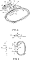
- FIG 1 shows a conventional embroidery system comprising a free-arm sewing machine, hereinafter also referred to as sewing machine 10 for short, an embroidery module 30 connected to the front of this sewing machine 10, and an embroidery frame 50 that can be moved in two directions of a sewing plane by embroidery module 30.
- the sewing machine 10 comprises a base plate 12, which serves as a standing surface, and a stand 11 on which an upper arm 13 with a machine head 15 and underneath a lower arm 17 protrude laterally.
- the upper side of the lower arm 17 or a needle plate arranged at its free end define the sewing plane.
- the embroidery module 30 comprises a first carrier 31, which is mounted on a second carrier 33 by a drive means so that it can be displaced in a first displacement direction P1.
- the direction of displacement P1 corresponds to the longitudinal direction of the lower arm 17 created a space. This also makes it possible to slip over a hose-like one Sheet of material over the lower arm 17 when the second carrier 33 is connected to the sewing machine 10.
- the first carrier 31 is an elongate beam on which a primary embroidery hoop adapter or, in general, a primary connecting means 37 is mounted so as to be displaceable in a second displacement direction P2 orthogonally to the first displacement direction P1 by a further drive means.
- figure 2 shows a conventional embroidery frame 50 with an inner first frame 51 and an outer second frame 53, between which a fabric 1 is held taut.
- the second frame 53 includes a tightening screw 55 for increasing and decreasing the frame circumference. By tightening the clamping screw 55, the second frame 53 can be pressed against the inner first frame 51.
- the fabric 1 is clamped between the first frame 51 and the second frame 53 .
- a secondary connection means 57 which can be releasably connected to the primary connection means 37 embroidery systems can only be processed to a limited extent.
- a hose opening 3 ( figure 3 ) must be at least large enough for the respective hose end to be able to accommodate the section with the secondary connecting means 57. Only sections of the fabric 1 be clamped, which are located close to one of the hose ends.
- FIG. 3 shows an example of a section of a conventional embroidery system in the area of the free end of the forearm 17.
- a section of a tubular fabric 1, for example a sleeve, is clamped in the embroidery frame 50.
- the inner first frame 51 rests on the outside of the fabric 1, the outer second frame 53 on the inside.
- the sleeve is partially slipped over the forearm 17 such that the underside of the first frame 51 holds the clamped portion of the fabric 1 in the sewing plane defined by the top of the forearm 17 .
- the secondary connecting means 57 is arranged directly on the outside of the second frame 53 and is latched to the corresponding primary connecting means 37 which is slidably mounted on the first carrier 31 of the embroidery module 30 .
- the connecting means 37, 57 there is only a narrow storage space between the outer frame 53 and the first carrier 31 with a width L1 of, for example one to two centimeters to slip over the end area of the sleeve there.
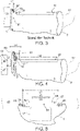
- figure 4 shows analogous to figure 3 a section of an embroidery system according to the invention in the area of the free end of the forearm 17.
- the inner first frame 51 rests on the outside of the fabric 1, the outer second frame 53 on the inside.
- the sleeve is partially slipped over the forearm 17 such that the underside of the first frame 51 holds the clamped portion of the fabric 1 in the sewing plane defined by the top of the forearm 17 .
- the secondary connecting means 57 is arranged at a radial distance on the outside of the first frame 51 and is rigidly connected to this first frame 51 by a bridge 61 .
- the bridge 61 comprises at least one connecting section 63, which connects the first frame 51 to the secondary connecting means 57 and bridges the second frame 53 and, if applicable, a section of a clamped sheet material 1 that projects beyond the second frame 53 when the second frame 53 is connected to the first frame 51 is connected.
- the distance L4 between the connecting section 63 and the second frame 53 is then at least as large as the maximum thickness of a sheet-like structure 1 to be clamped
- the minimum value of this distance L4 can be, for example, in the range from about 1 mm to about 5 mm and can be, for example, about 2 mm or about 3 mm.
- the distance L4 or the height of the free space below the connecting section 63 is preferably of the order of about 1 cm to about 10 cm, for example about 3 cm to about 5 cm.
- the bridge 61 is formed like a tunnel with a substantially rectangular cross-sectional shape.
- the height of the clearance between the first frame 51 and the secondary connecting means 57 essentially corresponds to the distance L4.
- bridge 61 may include one or more connecting portions 63, for example. These can, for example, as in figure 4 shown limit a cross-sectionally rectangular free space or include arc-like bulges with the same or different heights.
- the bridge 61 defines the underlying clearance at a level that is about 1 cm to about 5 cm above the upper level of the first frame 51.
- the upper limit of the free space can also be arranged at a higher level.
- the free space can be used as storage space for accommodating a section of the fabric 1 that protrudes beyond the embroidery frame 50 .
- Below and next to the first frame 51 is the free space that can be used as storage space is limited by the first carrier 31 and the second carrier 33 . By designing these supports 31, 33 appropriately, the usable storage space can be increased.
- the first beam 31 can be constructed like a bridge, a cross beam with a guide for the primary connecting means 37 being arranged at a distance above the second beam 33 by two lateral supports that are displaceably mounted on the second beam 33 .
- the storage space for the fabric 1 to be processed is expanded by the free space below the crossbeam.
- the second carrier 33 can include a recess 35, as shown in figure 1 is shown.
- the bridge 61 can include rib-like structures to increase the stability, in particular the flexural rigidity. Areas between such ribs can be material-free or can only be formed with comparatively thin layers of material. Such bridges 61 have a comparatively small mass and yet high rigidity and dimensional stability. Even in the event of large accelerations or rapid changes in the position of the primary connecting means 37, inertial forces acting on the bridge 61 and the elastic deformations of the bridge 61 caused thereby can be limited to a minimum. The puncture points of the sewing needle in the Flat structures 1 can therefore be precisely positioned even at high embroidery speeds.
- the bridge 61 can be made of plastic, metal or a light, dimensionally stable composite material, for example.
- bridges 61 can be made of metal, for example by forming a metal sheet or a grid. Bridges 61 may be integrally formed as a portion of secondary connector 57 and/or first frame 51, for example. Due to the smaller number of parts required, production and storage costs can be kept low.
- figure 5 schematically shows a cross section of an embroidery system in the area of the embroidery frame 50 looking in the direction of the bridge 61 which connects the inner first frame 51 to the secondary connecting means 57.
- the secondary connecting means 57 is designed like a beam and comprises spring-loaded latching elements which can be moved from a locking position into a release position by means of a respective handle 59 counter to the spring force.
- the latching elements When the embroidery hoop 50 is connected to the embroidery module 30, the latching elements are latched in their latching position with corresponding structures on the primary connecting means 37 in a form-fitting manner. To decouple the embroidery hoop 50 from the embroidery module 30, the locking elements are moved into the release position by exerting a compressive force on the handles 59 against the spring force.
- the connecting means 37, 57 for releasably coupling the Embroidery frame 50 with the embroidery module 30 could also be designed in a suitable other way.
- the width L6 of the bridge 61 is less than or equal to the length L5 of the beam-shaped secondary connecting means 57. This length L5 in turn is usually less than or equal to the length L7 of the first frame 51 in this direction.
- the secondary connecting means 57 preferably bears against the primary connecting means 37 at least in sections along its entire length L5 when it is connected thereto. As the length L5 increases, the stability of the connection is improved, and torques acting on the secondary connection means 57 when the primary connection means 37 is accelerated are smaller.
- Embroidery frames 50 can be optimized for specific purposes. Embroidery frames 50 for embroidering tubular material with a comparatively small circumference, such as sleeves, preferably have first frames 51 whose length L7 in the transverse direction of forearm 17 is of the order of magnitude of the width of forearm 17 and is, for example, about 6 cm to about 10 cm. The length L8 of the first frame 51 can be greater, the same size or smaller than its length L7.
- the maximum dimensions of the first frame 51 in the transverse direction or in the longitudinal direction of the bridge 61 are referred to as lengths L7 and L8, regardless of its shape, which can be, for example, rectangular, square, elliptical, oval, circular or in any other way.
- the bridge 61 can have an adapter 65 on the embroidery frame side and/or on the side of the secondary connecting means 57, with which the bridge 61 can be permanently or detachably attached to the inner frame 51 of an embroidery frame 50 and/or to the secondary fastening means 57.
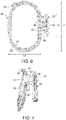
- figure 6 shows an example of an embroidery frame 50 in which the connecting portion 63 of the bridge 61 is arcuate. In each of the two end regions, a fastening arm of the respective adapter 65 protrudes on both sides of the bridge 61 . These mounting arms are screwed to the top of the first frame 51 by means of screws. If necessary, this connection can be released again using a tool.
- connections of an adapter 65 to an adjacent part can be fixed or detachable.
- Possible connection techniques are, for example, screws, welding, gluing, locking of locking elements or clamping, for example by means of clamping elements.
- figure 7 shows details of the arrangement figure 6 in the area of the bridge 61 in a side perspective view.
- the connecting section 63 comprises a plurality of reinforcing ribs 67 on its underside, of which figure 6 the foremost is visible.
- the width L6 of the connecting section 63 can also be greater and, for example, correspond approximately to the width L5 of a secondary connecting means 57. This improves the torsional rigidity.
- adapters 65 may include differently configured contact areas for attachment to secondary fasteners 57 and inner frame 51, rather than attachment arms.
- An example of such an embroidery hoop arrangement is shown in figure 8 as an exploded view and in figure 9 shown in three basic views.
- the adapter 65 on the embroidery frame includes a contact plate as the contact area, the shape of which is adapted to that of a corresponding depression 69 on the upper side of the inner frame 51 . This facilitates the assembly of these parts in a defined mutual position, with the positions of recesses 71 in the contact plate and bores 73 on the inner frame 51 matching.
- the bridge 61 is preferably releasably attached, for example by means of two quick-action clamping elements 75.
- Each of these quick-action clamping elements 75 comprises a bolt 77 which is guided through one of the recesses 71 and the bores 73 and is fastened to a plate 79 held on the inner frame 51 at the bottom.
- the bridge 61 can again releasably clamped to the inner frame 51 or connected to it.
- the second adapter 65 On the opposite side of the bridge 61, the second adapter 65 includes a contact surface for attaching the secondary connection means 57. If necessary, an intermediate plate 81 can be arranged between the contact surface and the secondary connection means 57, which serves, for example, as a spacer.
- Secondary connecting means 57 can be connected to different inner frames 51 in connection with such bridges 61 in a simple and detachable manner. Alternatively or additionally, in further embodiments, the secondary connection means 57 could be connected to the bridge 61 by means of an easily detachable quick connection (not shown).
- the embroidery hoop assembly as a whole or parts thereof such as the secondary connector 57, the bridge 61 or the inner hoop 51 may be uniquely identified by a code.
- This code is preferably an identification code with which the respective embroidery frame arrangement or the respective part can be clearly identified.
- This code is designed in such a way that it can be detected by a corresponding sensor device, for example mechanically, optically or electromagnetically.
- the sensor device comprises at least one sensor element, eg a sensing device, a camera, a pressure sensor, or a capacitive or inductive sensor (not shown).
- the code is preferably arranged at the secondary connection means 57 or at the bridge 61, ie close to the connection point with the primary connection means 37 of the embroidery module 30.
- Such codes can be easily detected by a sensor device arranged on the embroidery module 30, for example.
- the sensor device or parts thereof, such as evaluation electronics for processing sensor signals can also be arranged on the sewing machine 10, for example as part of the sewing machine controller.
- Corresponding reference values for each code are stored in the sewing machine control.
- the sewing machine controller identifies this embroidery hoop assembly or part of this embroidery hoop assembly based on the code detected in each case.
- the sewing machine control includes a memory in which further information relevant to controlling the sewing machine and the embroidery module in connection with the respective embroidery hoop arrangement is stored in association with each code.
- Such stored information can be, for example, reference values include, which define the position of a predetermined reference point of the embroidery frame assembly relative to a predetermined reference point of the sewing machine 10 when the embroidery frame 50 is connected to the embroidery module 30 and the embroidery module 30 to the sewing machine 10.
- properties can be stored which define the surface area that can be embroidered within the embroidery frame 50 .
- the sewing machine controller recognizes from a code arranged on this bridge 61 that the embroidery frame arrangement connected has not yet been clearly characterized. Information that is still missing can be specified, for example, by an operator via a user interface with input means.
- the sewing machine control can include, for example, stored data from a number of embroidery frames and can request the operator to select one of these embroidery frames.
Landscapes
- Engineering & Computer Science (AREA)
- Textile Engineering (AREA)
- Sewing Machines And Sewing (AREA)
Applications Claiming Priority (1)
| Application Number | Priority Date | Filing Date | Title |
|---|---|---|---|
| CH00267/21A CH718422A2 (de) | 2021-03-11 | 2021-03-11 | Sticksystem und Stickrahmenanordnung. |
Publications (2)
| Publication Number | Publication Date |
|---|---|
| EP4056744A1 true EP4056744A1 (fr) | 2022-09-14 |
| EP4056744B1 EP4056744B1 (fr) | 2023-03-15 |
Family
ID=76137963
Family Applications (1)
| Application Number | Title | Priority Date | Filing Date |
|---|---|---|---|
| EP21175926.1A Active EP4056744B1 (fr) | 2021-03-11 | 2021-05-26 | Système de broderie et agencement de métier à broder |
Country Status (3)
| Country | Link |
|---|---|
| US (1) | US11718940B2 (fr) |
| EP (1) | EP4056744B1 (fr) |
| CH (1) | CH718422A2 (fr) |
Cited By (1)
| Publication number | Priority date | Publication date | Assignee | Title |
|---|---|---|---|---|
| EP4497862A1 (fr) * | 2023-07-22 | 2025-01-29 | BERNINA International AG | Ensemble cadre de broderie |
Families Citing this family (1)
| Publication number | Priority date | Publication date | Assignee | Title |
|---|---|---|---|---|
| SE546956C2 (en) | 2023-08-18 | 2025-03-18 | Singer Sourcing Ltd Llc | Embroidery module and method |
Citations (5)
| Publication number | Priority date | Publication date | Assignee | Title |
|---|---|---|---|---|
| JPH10195751A (ja) * | 1996-12-27 | 1998-07-28 | Barudan Co Ltd | 刺繍枠 |
| EP0877112A2 (fr) * | 1997-04-28 | 1998-11-11 | Fritz Gegauf Ag Bernina-Nähmaschinenfabrik | Procédé et dispositif pour broder des ouvrages tubulaires |
| US6298800B1 (en) * | 1998-12-08 | 2001-10-09 | Mansukhlal K. Gala | Embroidery apparatus |
| US20050072346A1 (en) * | 2001-02-09 | 2005-04-07 | Yoshihisa Shoji | Embroidery frame transfer device and attachment |
| EP1783258A1 (fr) | 2005-11-07 | 2007-05-09 | BERNINA International AG | Module de broderie pour une machine à coudre à bras libre |
Family Cites Families (3)
| Publication number | Priority date | Publication date | Assignee | Title |
|---|---|---|---|---|
| US6679190B1 (en) * | 2001-06-01 | 2004-01-20 | Nick L. French | Fabric holder for embroidery frames |
| DE50208111D1 (de) * | 2001-06-25 | 2006-10-26 | Gegauf Fritz Ag | Vorrichtung zum lösbaren Befestigen eines Stickrahmens an einem Stickrahmenträger |
| JP2006087576A (ja) * | 2004-09-22 | 2006-04-06 | Aisin Seiki Co Ltd | 刺繍機 |
-
2021
- 2021-03-11 CH CH00267/21A patent/CH718422A2/de not_active Application Discontinuation
- 2021-05-26 EP EP21175926.1A patent/EP4056744B1/fr active Active
- 2021-07-08 US US17/370,073 patent/US11718940B2/en active Active
Patent Citations (5)
| Publication number | Priority date | Publication date | Assignee | Title |
|---|---|---|---|---|
| JPH10195751A (ja) * | 1996-12-27 | 1998-07-28 | Barudan Co Ltd | 刺繍枠 |
| EP0877112A2 (fr) * | 1997-04-28 | 1998-11-11 | Fritz Gegauf Ag Bernina-Nähmaschinenfabrik | Procédé et dispositif pour broder des ouvrages tubulaires |
| US6298800B1 (en) * | 1998-12-08 | 2001-10-09 | Mansukhlal K. Gala | Embroidery apparatus |
| US20050072346A1 (en) * | 2001-02-09 | 2005-04-07 | Yoshihisa Shoji | Embroidery frame transfer device and attachment |
| EP1783258A1 (fr) | 2005-11-07 | 2007-05-09 | BERNINA International AG | Module de broderie pour une machine à coudre à bras libre |
Cited By (2)
| Publication number | Priority date | Publication date | Assignee | Title |
|---|---|---|---|---|
| EP4497862A1 (fr) * | 2023-07-22 | 2025-01-29 | BERNINA International AG | Ensemble cadre de broderie |
| US12467176B1 (en) * | 2023-07-22 | 2025-11-11 | Bernina International Ag | Embroidery frame arrangement |
Also Published As
| Publication number | Publication date |
|---|---|
| EP4056744B1 (fr) | 2023-03-15 |
| US20220290348A1 (en) | 2022-09-15 |
| CH718422A2 (de) | 2022-09-15 |
| US11718940B2 (en) | 2023-08-08 |
Similar Documents
| Publication | Publication Date | Title |
|---|---|---|
| DE1950759C3 (de) | Chirurgisches Instrument | |
| DE19820646B4 (de) | Drückerfußvorrichtung für eine Nähmaschine | |
| EP4056744B1 (fr) | Système de broderie et agencement de métier à broder | |
| DE4208726C2 (de) | Nähmaschine mit Nähguthalter | |
| EP3290152B1 (fr) | Porte-piece | |
| DE2927142C2 (de) | Mehrkopfstickmaschine | |
| DE10038511A1 (de) | Längs-Bearbeitungs-Maschine für Wellpappe-Bahnen | |
| DE102007018081A1 (de) | Befestigungsgerät und -system | |
| EP2573245B1 (fr) | Machine à broder avec dispositif de tension du matériau | |
| DE2025187A1 (de) | Nahmaschine mit Fadenabschneider | |
| EP1886765A1 (fr) | Procédé de support d'outil et dispositif de traitement de sections plates | |
| EP1974883B1 (fr) | Procédé et dispositif de positionnement d'éléments de coffrage de bordure sur une table de moulage | |
| DE102017102854B3 (de) | Umreifungsvorrichtung zum Umreifen eines Packguts | |
| DE102008045460A1 (de) | Nähmaschine | |
| AT392984B (de) | Nadelmaschine | |
| AT518255B1 (de) | Werkzeugwechselvorrichtung für eine Abkantpresse und Verfahren zum Durchführen eines Werkzeugwechsels | |
| DE8114009U1 (de) | "zusatzvorrichtung fuer eine knopfannaehmaschine" | |
| EP1270788B1 (fr) | Dispositif pour attacher de manière amovible un cadre à broder à un support de cadre à broder | |
| EP1783258B1 (fr) | Module de broderie pour une machine à coudre à bras libre | |
| DE3025156C2 (de) | Presse mit einem Stanz- und/oder Preßwerkzeug | |
| DE69119788T2 (de) | Vorrichtung zum spannen eines werkstücks in einer spannvorrichtung, einem werktisch oder dgl. | |
| WO2018178160A1 (fr) | Dispositif de maintien pour dispositifs de traitement medical | |
| DE102004033886B4 (de) | Halteanordnung für Container | |
| EP1377395B1 (fr) | Machine de pliage, en particulier presse a estamper ou a plier, pourvue d'un outil inferieur reglable | |
| DE4444178C5 (de) | Verfahren zum Verkoppeln eines ersten Beschlags mit einem zweiten Beschlag und Vorrichtung für die automatische Montage von Beschlägen an Fenstern und dergleichen |
Legal Events
| Date | Code | Title | Description |
|---|---|---|---|
| STAA | Information on the status of an ep patent application or granted ep patent |
Free format text: STATUS: EXAMINATION IS IN PROGRESS |
|
| PUAI | Public reference made under article 153(3) epc to a published international application that has entered the european phase |
Free format text: ORIGINAL CODE: 0009012 |
|
| 17P | Request for examination filed |
Effective date: 20220228 |
|
| AK | Designated contracting states |
Kind code of ref document: A1 Designated state(s): AL AT BE BG CH CY CZ DE DK EE ES FI FR GB GR HR HU IE IS IT LI LT LU LV MC MK MT NL NO PL PT RO RS SE SI SK SM TR |
|
| GRAP | Despatch of communication of intention to grant a patent |
Free format text: ORIGINAL CODE: EPIDOSNIGR1 |
|
| STAA | Information on the status of an ep patent application or granted ep patent |
Free format text: STATUS: GRANT OF PATENT IS INTENDED |
|
| INTG | Intention to grant announced |
Effective date: 20221013 |
|
| GRAS | Grant fee paid |
Free format text: ORIGINAL CODE: EPIDOSNIGR3 |
|
| GRAA | (expected) grant |
Free format text: ORIGINAL CODE: 0009210 |
|
| STAA | Information on the status of an ep patent application or granted ep patent |
Free format text: STATUS: THE PATENT HAS BEEN GRANTED |
|
| AK | Designated contracting states |
Kind code of ref document: B1 Designated state(s): AL AT BE BG CH CY CZ DE DK EE ES FI FR GB GR HR HU IE IS IT LI LT LU LV MC MK MT NL NO PL PT RO RS SE SI SK SM TR |
|
| REG | Reference to a national code |
Ref country code: CH Ref legal event code: EP Ref country code: GB Ref legal event code: FG4D Free format text: NOT ENGLISH |
|
| REG | Reference to a national code |
Ref country code: DE Ref legal event code: R096 Ref document number: 502021000492 Country of ref document: DE |
|
| REG | Reference to a national code |
Ref country code: IE Ref legal event code: FG4D Free format text: LANGUAGE OF EP DOCUMENT: GERMAN |
|
| REG | Reference to a national code |
Ref country code: AT Ref legal event code: REF Ref document number: 1554061 Country of ref document: AT Kind code of ref document: T Effective date: 20230415 |
|
| REG | Reference to a national code |
Ref country code: LT Ref legal event code: MG9D |
|
| REG | Reference to a national code |
Ref country code: NL Ref legal event code: MP Effective date: 20230315 |
|
| PG25 | Lapsed in a contracting state [announced via postgrant information from national office to epo] |
Ref country code: RS Free format text: LAPSE BECAUSE OF FAILURE TO SUBMIT A TRANSLATION OF THE DESCRIPTION OR TO PAY THE FEE WITHIN THE PRESCRIBED TIME-LIMIT Effective date: 20230315 Ref country code: NO Free format text: LAPSE BECAUSE OF FAILURE TO SUBMIT A TRANSLATION OF THE DESCRIPTION OR TO PAY THE FEE WITHIN THE PRESCRIBED TIME-LIMIT Effective date: 20230615 Ref country code: LV Free format text: LAPSE BECAUSE OF FAILURE TO SUBMIT A TRANSLATION OF THE DESCRIPTION OR TO PAY THE FEE WITHIN THE PRESCRIBED TIME-LIMIT Effective date: 20230315 Ref country code: LT Free format text: LAPSE BECAUSE OF FAILURE TO SUBMIT A TRANSLATION OF THE DESCRIPTION OR TO PAY THE FEE WITHIN THE PRESCRIBED TIME-LIMIT Effective date: 20230315 Ref country code: HR Free format text: LAPSE BECAUSE OF FAILURE TO SUBMIT A TRANSLATION OF THE DESCRIPTION OR TO PAY THE FEE WITHIN THE PRESCRIBED TIME-LIMIT Effective date: 20230315 |
|
| PG25 | Lapsed in a contracting state [announced via postgrant information from national office to epo] |
Ref country code: SE Free format text: LAPSE BECAUSE OF FAILURE TO SUBMIT A TRANSLATION OF THE DESCRIPTION OR TO PAY THE FEE WITHIN THE PRESCRIBED TIME-LIMIT Effective date: 20230315 Ref country code: NL Free format text: LAPSE BECAUSE OF FAILURE TO SUBMIT A TRANSLATION OF THE DESCRIPTION OR TO PAY THE FEE WITHIN THE PRESCRIBED TIME-LIMIT Effective date: 20230315 Ref country code: GR Free format text: LAPSE BECAUSE OF FAILURE TO SUBMIT A TRANSLATION OF THE DESCRIPTION OR TO PAY THE FEE WITHIN THE PRESCRIBED TIME-LIMIT Effective date: 20230616 Ref country code: FI Free format text: LAPSE BECAUSE OF FAILURE TO SUBMIT A TRANSLATION OF THE DESCRIPTION OR TO PAY THE FEE WITHIN THE PRESCRIBED TIME-LIMIT Effective date: 20230315 |
|
| PG25 | Lapsed in a contracting state [announced via postgrant information from national office to epo] |
Ref country code: SM Free format text: LAPSE BECAUSE OF FAILURE TO SUBMIT A TRANSLATION OF THE DESCRIPTION OR TO PAY THE FEE WITHIN THE PRESCRIBED TIME-LIMIT Effective date: 20230315 Ref country code: RO Free format text: LAPSE BECAUSE OF FAILURE TO SUBMIT A TRANSLATION OF THE DESCRIPTION OR TO PAY THE FEE WITHIN THE PRESCRIBED TIME-LIMIT Effective date: 20230315 Ref country code: PT Free format text: LAPSE BECAUSE OF FAILURE TO SUBMIT A TRANSLATION OF THE DESCRIPTION OR TO PAY THE FEE WITHIN THE PRESCRIBED TIME-LIMIT Effective date: 20230717 Ref country code: ES Free format text: LAPSE BECAUSE OF FAILURE TO SUBMIT A TRANSLATION OF THE DESCRIPTION OR TO PAY THE FEE WITHIN THE PRESCRIBED TIME-LIMIT Effective date: 20230315 Ref country code: EE Free format text: LAPSE BECAUSE OF FAILURE TO SUBMIT A TRANSLATION OF THE DESCRIPTION OR TO PAY THE FEE WITHIN THE PRESCRIBED TIME-LIMIT Effective date: 20230315 Ref country code: CZ Free format text: LAPSE BECAUSE OF FAILURE TO SUBMIT A TRANSLATION OF THE DESCRIPTION OR TO PAY THE FEE WITHIN THE PRESCRIBED TIME-LIMIT Effective date: 20230315 |
|
| PG25 | Lapsed in a contracting state [announced via postgrant information from national office to epo] |
Ref country code: SK Free format text: LAPSE BECAUSE OF FAILURE TO SUBMIT A TRANSLATION OF THE DESCRIPTION OR TO PAY THE FEE WITHIN THE PRESCRIBED TIME-LIMIT Effective date: 20230315 Ref country code: PL Free format text: LAPSE BECAUSE OF FAILURE TO SUBMIT A TRANSLATION OF THE DESCRIPTION OR TO PAY THE FEE WITHIN THE PRESCRIBED TIME-LIMIT Effective date: 20230315 Ref country code: IS Free format text: LAPSE BECAUSE OF FAILURE TO SUBMIT A TRANSLATION OF THE DESCRIPTION OR TO PAY THE FEE WITHIN THE PRESCRIBED TIME-LIMIT Effective date: 20230715 |
|
| REG | Reference to a national code |
Ref country code: DE Ref legal event code: R097 Ref document number: 502021000492 Country of ref document: DE |
|
| PG25 | Lapsed in a contracting state [announced via postgrant information from national office to epo] |
Ref country code: MC Free format text: LAPSE BECAUSE OF FAILURE TO SUBMIT A TRANSLATION OF THE DESCRIPTION OR TO PAY THE FEE WITHIN THE PRESCRIBED TIME-LIMIT Effective date: 20230315 |
|
| PLBE | No opposition filed within time limit |
Free format text: ORIGINAL CODE: 0009261 |
|
| STAA | Information on the status of an ep patent application or granted ep patent |
Free format text: STATUS: NO OPPOSITION FILED WITHIN TIME LIMIT |
|
| REG | Reference to a national code |
Ref country code: BE Ref legal event code: MM Effective date: 20230531 |
|
| PG25 | Lapsed in a contracting state [announced via postgrant information from national office to epo] |
Ref country code: SI Free format text: LAPSE BECAUSE OF FAILURE TO SUBMIT A TRANSLATION OF THE DESCRIPTION OR TO PAY THE FEE WITHIN THE PRESCRIBED TIME-LIMIT Effective date: 20230315 Ref country code: MC Free format text: LAPSE BECAUSE OF FAILURE TO SUBMIT A TRANSLATION OF THE DESCRIPTION OR TO PAY THE FEE WITHIN THE PRESCRIBED TIME-LIMIT Effective date: 20230315 Ref country code: LU Free format text: LAPSE BECAUSE OF NON-PAYMENT OF DUE FEES Effective date: 20230526 Ref country code: DK Free format text: LAPSE BECAUSE OF FAILURE TO SUBMIT A TRANSLATION OF THE DESCRIPTION OR TO PAY THE FEE WITHIN THE PRESCRIBED TIME-LIMIT Effective date: 20230315 |
|
| 26N | No opposition filed |
Effective date: 20231218 |
|
| REG | Reference to a national code |
Ref country code: IE Ref legal event code: MM4A |
|
| PG25 | Lapsed in a contracting state [announced via postgrant information from national office to epo] |
Ref country code: IE Free format text: LAPSE BECAUSE OF NON-PAYMENT OF DUE FEES Effective date: 20230526 |
|
| PG25 | Lapsed in a contracting state [announced via postgrant information from national office to epo] |
Ref country code: IE Free format text: LAPSE BECAUSE OF NON-PAYMENT OF DUE FEES Effective date: 20230526 |
|
| PG25 | Lapsed in a contracting state [announced via postgrant information from national office to epo] |
Ref country code: IT Free format text: LAPSE BECAUSE OF FAILURE TO SUBMIT A TRANSLATION OF THE DESCRIPTION OR TO PAY THE FEE WITHIN THE PRESCRIBED TIME-LIMIT Effective date: 20230315 Ref country code: FR Free format text: LAPSE BECAUSE OF NON-PAYMENT OF DUE FEES Effective date: 20230531 Ref country code: BE Free format text: LAPSE BECAUSE OF NON-PAYMENT OF DUE FEES Effective date: 20230531 |
|
| PG25 | Lapsed in a contracting state [announced via postgrant information from national office to epo] |
Ref country code: BG Free format text: LAPSE BECAUSE OF FAILURE TO SUBMIT A TRANSLATION OF THE DESCRIPTION OR TO PAY THE FEE WITHIN THE PRESCRIBED TIME-LIMIT Effective date: 20230315 |
|
| PG25 | Lapsed in a contracting state [announced via postgrant information from national office to epo] |
Ref country code: BG Free format text: LAPSE BECAUSE OF FAILURE TO SUBMIT A TRANSLATION OF THE DESCRIPTION OR TO PAY THE FEE WITHIN THE PRESCRIBED TIME-LIMIT Effective date: 20230315 |
|
| PGFP | Annual fee paid to national office [announced via postgrant information from national office to epo] |
Ref country code: DE Payment date: 20250528 Year of fee payment: 5 |
|
| PGFP | Annual fee paid to national office [announced via postgrant information from national office to epo] |
Ref country code: GB Payment date: 20250520 Year of fee payment: 5 |
|
| PGFP | Annual fee paid to national office [announced via postgrant information from national office to epo] |
Ref country code: CH Payment date: 20250601 Year of fee payment: 5 |
|
| PGFP | Annual fee paid to national office [announced via postgrant information from national office to epo] |
Ref country code: AT Payment date: 20250721 Year of fee payment: 5 |
|
| PG25 | Lapsed in a contracting state [announced via postgrant information from national office to epo] |
Ref country code: CY Free format text: LAPSE BECAUSE OF FAILURE TO SUBMIT A TRANSLATION OF THE DESCRIPTION OR TO PAY THE FEE WITHIN THE PRESCRIBED TIME-LIMIT; INVALID AB INITIO Effective date: 20210526 |
|
| PG25 | Lapsed in a contracting state [announced via postgrant information from national office to epo] |
Ref country code: HU Free format text: LAPSE BECAUSE OF FAILURE TO SUBMIT A TRANSLATION OF THE DESCRIPTION OR TO PAY THE FEE WITHIN THE PRESCRIBED TIME-LIMIT; INVALID AB INITIO Effective date: 20210526 |
|
| PG25 | Lapsed in a contracting state [announced via postgrant information from national office to epo] |
Ref country code: TR Free format text: LAPSE BECAUSE OF FAILURE TO SUBMIT A TRANSLATION OF THE DESCRIPTION OR TO PAY THE FEE WITHIN THE PRESCRIBED TIME-LIMIT Effective date: 20230315 |