EP4056767A2 - Station de rinçage - Google Patents
Station de rinçage Download PDFInfo
- Publication number
- EP4056767A2 EP4056767A2 EP22158258.8A EP22158258A EP4056767A2 EP 4056767 A2 EP4056767 A2 EP 4056767A2 EP 22158258 A EP22158258 A EP 22158258A EP 4056767 A2 EP4056767 A2 EP 4056767A2
- Authority
- EP
- European Patent Office
- Prior art keywords
- station
- lines
- flushing
- flow
- rinsing
- Prior art date
- Legal status (The legal status is an assumption and is not a legal conclusion. Google has not performed a legal analysis and makes no representation as to the accuracy of the status listed.)
- Granted
Links
Images



Classifications
-
- E—FIXED CONSTRUCTIONS
- E03—WATER SUPPLY; SEWERAGE
- E03B—INSTALLATIONS OR METHODS FOR OBTAINING, COLLECTING, OR DISTRIBUTING WATER
- E03B7/00—Water main or service pipe systems
- E03B7/006—Arrangements or methods for cleaning or refurbishing water conduits
-
- E—FIXED CONSTRUCTIONS
- E03—WATER SUPPLY; SEWERAGE
- E03B—INSTALLATIONS OR METHODS FOR OBTAINING, COLLECTING, OR DISTRIBUTING WATER
- E03B7/00—Water main or service pipe systems
- E03B7/07—Arrangement of devices, e.g. filters, flow controls, measuring devices, siphons or valves, in the pipe systems
- E03B7/08—Arrangement of draining devices, e.g. manual shut-off valves
-
- E—FIXED CONSTRUCTIONS
- E03—WATER SUPPLY; SEWERAGE
- E03C—DOMESTIC PLUMBING INSTALLATIONS FOR FRESH WATER OR WASTE WATER; SINKS
- E03C1/00—Domestic plumbing installations for fresh water or waste water; Sinks
- E03C1/02—Plumbing installations for fresh water
- E03C1/05—Arrangements of devices on wash-basins, baths, sinks, or the like for remote control of taps
- E03C1/055—Electrical control devices, e.g. with push buttons, control panels or the like
- E03C1/057—Electrical control devices, e.g. with push buttons, control panels or the like touchless, i.e. using sensors
-
- E—FIXED CONSTRUCTIONS
- E03—WATER SUPPLY; SEWERAGE
- E03C—DOMESTIC PLUMBING INSTALLATIONS FOR FRESH WATER OR WASTE WATER; SINKS
- E03C1/00—Domestic plumbing installations for fresh water or waste water; Sinks
- E03C1/02—Plumbing installations for fresh water
- E03C1/10—Devices for preventing contamination of drinking-water pipes, e.g. means for aerating self-closing flushing valves
-
- E—FIXED CONSTRUCTIONS
- E03—WATER SUPPLY; SEWERAGE
- E03C—DOMESTIC PLUMBING INSTALLATIONS FOR FRESH WATER OR WASTE WATER; SINKS
- E03C1/00—Domestic plumbing installations for fresh water or waste water; Sinks
- E03C1/12—Plumbing installations for waste water; Basins or fountains connected thereto; Sinks
- E03C1/24—Overflow devices for basins or baths
-
- F—MECHANICAL ENGINEERING; LIGHTING; HEATING; WEAPONS; BLASTING
- F24—HEATING; RANGES; VENTILATING
- F24D—DOMESTIC- OR SPACE-HEATING SYSTEMS, e.g. CENTRAL HEATING SYSTEMS; DOMESTIC HOT-WATER SUPPLY SYSTEMS; ELEMENTS OR COMPONENTS THEREFOR
- F24D17/00—Domestic hot-water supply systems
- F24D17/0073—Arrangements for preventing the occurrence or proliferation of microorganisms in the water
-
- E—FIXED CONSTRUCTIONS
- E03—WATER SUPPLY; SEWERAGE
- E03C—DOMESTIC PLUMBING INSTALLATIONS FOR FRESH WATER OR WASTE WATER; SINKS
- E03C1/00—Domestic plumbing installations for fresh water or waste water; Sinks
- E03C1/12—Plumbing installations for waste water; Basins or fountains connected thereto; Sinks
- E03C1/24—Overflow devices for basins or baths
- E03C2001/2406—Overflow alarm devices
-
- E—FIXED CONSTRUCTIONS
- E03—WATER SUPPLY; SEWERAGE
- E03C—DOMESTIC PLUMBING INSTALLATIONS FOR FRESH WATER OR WASTE WATER; SINKS
- E03C2201/00—Details, devices or methods not otherwise provided for
- E03C2201/60—Reducing noise in plumbing systems
Definitions
- the invention relates to a rinsing station with a connection piece for a hot water line, a connection piece for a cold water line, a receptacle with a siphon for draining the water, lines on the connection pieces which direct the water from the connection pieces into the receptacle, at least one sensor, one with the Sensor-connected controller, a valve operable in the lines, wherein the controller is coupled to the operable valve and the operable valve can be opened by the controller for flushing the hot water line and the cold water line, respectively.
- Rinsing stations are necessary to avoid the formation of legionella or germs in water that has been standing for a long time. Legionella are a serious health risk, especially for older or immunocompromised people. All operators or landlords of commercial buildings have the obligation to ensure hygienically safe water. For this reason, flushing stations are usually installed in new commercial buildings.
- a disadvantage of the previously known rinsing stations is the relatively high level of noise emitted during the rinsing process.
- the invention is therefore based on the object of demonstrating a solution by which the noise emission is reduced.
- the object is achieved in that a flow limiter and a flow straightener are integrated in each of the lines.
- the flow limiter limits the amount of water and the flow straightener creates a laminar flow.
- the flow restrictor reduces the flow rate to 16 liters per minute and the flow straightener to 15 liters per minute and also causes a laminar flow in the line.
- the flow limiter is arranged in front of the flow straightener in the direction of flow, so that the water to be flushed is guided into the receptacle with a laminar flow.
- the valve is designed as a ball valve.
- Ball valves do not tend to "water hammer", i.e. pressure surge or water hammer effect, which would lead to vibration and high noise emissions.
- the rinsing station has a housing made of expanded polypropylene, from which only the connecting pieces are guided.
- a further noise reduction is achieved by completely encapsulating the rinsing station.
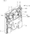
- figure 1 shows an open rinsing station SS in an oblique view, which has a connection piece AS1 for a hot water line and a further connection piece AS2 for a cold water line.
- the connecting pieces are formed on lines L1 or L2 within the rinsing station, which direct the water down into a collecting container AB.
- connection pieces AS1 and AS2 refer purely functionally to the connections to the hot or cold water pipe.
- the connecting pieces are realized by a union nut and an adapter piece. Any other implementation would also be possible, such as an internal thread or a quick connection technique.
- the water is drained downwards via a siphon SP out of the rinsing station into a drain pipe.
- the lines L1 and L2 also have connection pieces AS3 and AS4 for connecting the hot water connection or cold water connection of a washbasin.
- a waste water pipe AWR with a connecting piece AS5 is provided in the rinsing station SS, to which the drain of a washbasin can be connected.
- the waste water pipe also opens into the collecting tank AB.
- the rinsing station SS also has a controller ST, which can open the lines L1 and L2 via electronically actuated valves V for rinsing the hot or cold water lines.
- Sensors S are attached to the lines L1 and L2, which are connected to the controller ST and which can measure whether or not water is flowing in the lines L1 or L2. After a preset period of time in which the sensors S measure that no water is flowing, the control ST, which in turn is connected to the electronically actuated valves V, opens the valves V to flush the lines L1 and L2 and thus the lines thereon connected hot and cold water pipes.
- the rinsing station SS has a housing G which is made of expanded polypropylene. Only the rear part of the housing G is in figure 1 shown.
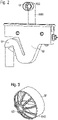
- figure 2 shows isolated the collection container AB of the rinsing station SS and the siphon SB which is designed in one piece with the collection container AB. Also shown is the waste water pipe AWR with a connection piece AS5, in which a dirt trap SF is integrated.
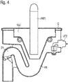
- the mud flap SF is in figure 3 shown in oblique view.
- the dirt trap SF has a pipe section RAS and a lattice structure GS and can thus be easily pushed into the connection piece AS5 of the waste water pipe AWR.
- the mud flap is made using 3D printing.
- the dirt trap ensures that heavy soiling does not get into the rinsing station SS or into the collection container AB of the rinsing station SS and could possibly clog the siphon SP there.
- cleaning the dirt trap SF either with chemicals or by dismantling and cleaning, the blockage can be easily removed and there is no risk of the siphon SP becoming blocked and water penetrating from the collection container AB.
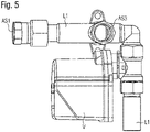
- FIG figure 4 shows a section through the parts according to FIG figure 2 the rinsing station SS.
- the collection container AB is funnel-shaped in the direction of the drain.
- a splash guard SSZ is arranged, which is also funnel-shaped downwards and is mounted at a distance from the collection container AB.
- the AWR discharge pipe at a distance from the SSZ splash guard as well as the lines L1 and L2 for hot water and cold water flushing, which however in figure 4 are not shown.
- An overflow sensor UES is arranged in the collection container AB, which can detect water accumulating in the collection container AB.
- the overflow sensor UES is coupled to the controller ST, which closes the electronically actuated valves V when the overflow sensor UES is triggered and also a further flushing via the sensors S stops until the cause of the water backing up in the collecting tank AB has been remedied and the ST control has been reset accordingly.
- the collection container is closed by a cover D through which the waste water pipe AWR and the lines L1 and L2 open.
- figure 5 shows the line L1 with the connection piece AS1 for connecting to a hot water line and the connection piece AS3 for connecting the hot water connection of a washbasin. Furthermore, the electronically operable valve V is integrated in the line L1, with which the line L1 can be opened and also closed again for flushing.
- the line L1 for the rinsing station SS is L-shaped with a horizontal and a vertical section, whereby both the horizontal section and the vertical section can be rotated about their longitudinal axis, so that the identical component as in figure 5 shown can be used.
- FIG figure 6 shows a section through the line L1 according to FIG figure 5 the electronically operable valve V is not shown.
- a flow limiter DB and a flow straightener SG are integrated in the line L1 in the direction of flow from the connection piece AS1 in the direction of the collection container AB.
- the Figure 7A shows the flow restrictor in an oblique view, the Figure 7B in the top view and the Figure 7C the in Figure 7B drawn cut.
- the flow limiter reduces the flow to 16 liters per minute.
- the flow limiter DB is a standard component that can be obtained from Neoperl.
- the flow limiter DB is used when installing line L1 upstream of valve V.
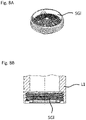
- Figure 8A shows the flow straightener SG in an oblique view and in Figure 8B a sectional view through the lower area of the line L1 in which the flow straightener SG is used.
- the flow straightener is also a component from the Neoperl company and can be screwed into a corresponding internal thread in the outlet of line L1 from below using an assembly wrench.
- the flow straightener allows a flow of 15 liters per minute and creates a laminar flow.
- the flow rate is reduced and the water flows in a laminar manner into the splash guard SSZ and then into the collecting tank AB.
- greater noise emissions are avoided during the rinsing process, and a rinsing station with very low noise emissions is thus created.
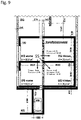
- the figure 9 shows a measurement setup for the flushing station SS according to the invention, in order to measure the noise emissions in the adjacent rooms as well as those lying below or diagonally below.
- the measurements were carried out by the Fraunhofer Institute in accordance with DIN standard 4109.
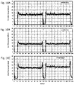
- the Figure 10A shows the noise emission during the flushing process in the basement room at the front.
- Figure 10B shows the noise emission in the room UG behind and Figure 10C the noise emission in the ground floor room at the back.
- the noise emission is around 20 and 15 decibels, respectively, and in the room on the ground floor at the back, i.e. adjacent to the room with the SS rinsing station, it is 20 and just over 20 decibels, respectively.
- DIN 4109-5 which requires noise emissions of less than 25 decibels
- VDE 4100 SSt III which require emissions of less than 22 decibels
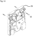
- figure 11 shows the SS flushing station mounted on the wall using two screws S1 and S2.
- figure 12 shows a mounting frame MR, in which the rinsing station can also be mounted.
- the rinsing station is completely surrounded by the housing G, which also contributes to noise reduction to a certain extent. Only the connection pieces AS3 and AS4 for the cold and hot water connection of the washbasin and AS5 for the waste water connection of the washbasin protrude from the housing. Laterally also the connection pieces AS1 and AS2 (in figure 12 not visible) for the hot and cold water pipe.
- Both installation variants allow the SS flushing station to be installed in a very space-saving manner, since the intended connection space is used for a washbasin.
Landscapes
- Engineering & Computer Science (AREA)
- Water Supply & Treatment (AREA)
- Health & Medical Sciences (AREA)
- Life Sciences & Earth Sciences (AREA)
- Hydrology & Water Resources (AREA)
- Public Health (AREA)
- Thermal Sciences (AREA)
- Physics & Mathematics (AREA)
- Environmental & Geological Engineering (AREA)
- Chemical & Material Sciences (AREA)
- Combustion & Propulsion (AREA)
- Mechanical Engineering (AREA)
- General Engineering & Computer Science (AREA)
- Sink And Installation For Waste Water (AREA)
- Cleaning By Liquid Or Steam (AREA)
- Domestic Plumbing Installations (AREA)
- Cleaning In General (AREA)
Applications Claiming Priority (1)
| Application Number | Priority Date | Filing Date | Title |
|---|---|---|---|
| DE102021105677.2A DE102021105677A1 (de) | 2021-03-09 | 2021-03-09 | Spülstation |
Publications (3)
| Publication Number | Publication Date |
|---|---|
| EP4056767A2 true EP4056767A2 (fr) | 2022-09-14 |
| EP4056767A3 EP4056767A3 (fr) | 2022-12-07 |
| EP4056767B1 EP4056767B1 (fr) | 2025-08-27 |
Family
ID=80780705
Family Applications (1)
| Application Number | Title | Priority Date | Filing Date |
|---|---|---|---|
| EP22158258.8A Active EP4056767B1 (fr) | 2021-03-09 | 2022-02-23 | Station de rinçage |
Country Status (4)
| Country | Link |
|---|---|
| US (1) | US11913199B2 (fr) |
| EP (1) | EP4056767B1 (fr) |
| CA (1) | CA3150988A1 (fr) |
| DE (1) | DE102021105677A1 (fr) |
Family Cites Families (13)
| Publication number | Priority date | Publication date | Assignee | Title |
|---|---|---|---|---|
| US2045479A (en) * | 1935-11-11 | 1936-06-23 | Mary A M Luff | Vacuum breaker |
| DE3446842A1 (de) * | 1984-03-27 | 1985-10-31 | Amcor Ltd., Tel Aviv | Fluessigkeitsfiltervorrichtung |
| GB2264051A (en) | 1992-02-04 | 1993-08-18 | Robert Miles Walter Willis | A trap for a basin waste pipe plug hole |
| AT507052B1 (de) | 2008-06-17 | 2010-07-15 | Baumgartner Johannes | Wandeinbaublock für installationen |
| DE102011013955B4 (de) * | 2011-03-14 | 2018-12-27 | Viega Technology Gmbh & Co. Kg | Verfahren zum selbsttätigen Spülen |
| DE202013102154U1 (de) | 2013-05-16 | 2014-08-18 | Hans Sasserath Gmbh & Co. Kg | Anordnung zur Durchführung einer Hygienespülung in einer Wasserinstallation |
| DE202014007233U1 (de) * | 2014-09-04 | 2015-12-09 | Gebr. Kemper Gmbh + Co. Kg Metallwerke | Steuervorrichtung und Trink- und/oder Brauchwassersystem mit einer solchen Steuervorrichtung |
| DE102015113886A1 (de) | 2015-08-21 | 2017-02-23 | Viega Gmbh & Co. Kg | Vorrichtung, System und Verfahren zum selbsttätigen Spülen mit Mehrfachventil |
| DE202016100854U1 (de) * | 2016-02-18 | 2017-05-23 | Uponor Innovation Ab | Sicherungseinrichtung |
| DE202016100853U1 (de) * | 2016-02-18 | 2017-05-23 | Uponor Innovation Ab | Spülstation für ein Ring- oder Reihenleitungssystem, Ringleitungssystem sowie Reihenleitungssystem |
| DE202017100660U1 (de) * | 2017-02-08 | 2018-05-11 | Viega Technology Gmbh & Co. Kg | Spülvorrichtung für eine Sanitäreinrichtung sowie Toiletten- oder Urinalspülung |
| DE102017111074A1 (de) | 2017-05-22 | 2018-11-22 | Schell Gmbh & Co. Kg | Vorrichtung zur Ableitung von bei der Spülung und/oder thermischen Desinfektion von Rohrleitungen in Sanitärinstallationen anfallenden Spülwassers |
| DE102019105614A1 (de) * | 2019-03-06 | 2020-09-10 | Viega Technology Gmbh & Co. Kg | Spülkasten, insbesondere Unterputzspülkasten, für ein WC oder Urinal, sowie Trinkwasserleitungssystem mit einem Spülkasten |
-
2021
- 2021-03-09 DE DE102021105677.2A patent/DE102021105677A1/de active Pending
-
2022
- 2022-02-23 EP EP22158258.8A patent/EP4056767B1/fr active Active
- 2022-02-24 CA CA3150988A patent/CA3150988A1/fr active Pending
- 2022-03-04 US US17/687,509 patent/US11913199B2/en active Active
Also Published As
| Publication number | Publication date |
|---|---|
| EP4056767B1 (fr) | 2025-08-27 |
| DE102021105677A1 (de) | 2022-09-15 |
| US11913199B2 (en) | 2024-02-27 |
| US20220290415A1 (en) | 2022-09-15 |
| EP4056767A3 (fr) | 2022-12-07 |
| CA3150988A1 (fr) | 2022-09-09 |
Similar Documents
| Publication | Publication Date | Title |
|---|---|---|
| EP2159336B1 (fr) | Utilisation d'une bouche d'égout | |
| EP1964983A1 (fr) | Dispositif destiné au lavage automatique de conduites d'eau | |
| EP2895659B1 (fr) | Dispositif pour réaliser un rinçage hygiénique dans une installation hydraulique | |
| DE202008011010U1 (de) | Ablauf | |
| EP4056767B1 (fr) | Station de rinçage | |
| EP1936045A1 (fr) | Dispositif d'installation pour un dispositif sanitaire et dispositif sanitaire avec un tel dispositif d'installation | |
| EP4089240A2 (fr) | Module de chasse d'eau de toilettes et toilettes | |
| EP0185109B1 (fr) | Siphon | |
| DE19536771C2 (de) | Regenwassernutzungsanlage | |
| EP4069910B1 (fr) | Dispositif de drainage | |
| EP3564664B1 (fr) | Robinetterie d'eau pourvu de système automatique de rinçage | |
| DE19749779A1 (de) | Geruchsverschluß für ein Abflußrohr, insbesondere für das Abflußrohr eines Waschbeckens, einer Duschwanne oder dergleichen | |
| DE20105187U1 (de) | Bodenablauf mit herausnehmbarem Geruchsverschlusselement | |
| DE8906228U1 (de) | Einbaugeruchsverschluß | |
| EP4105393B1 (fr) | Dispositif de rinçage d'hygiène | |
| DE10114358B4 (de) | Sanitärarmatur | |
| EP4015717B1 (fr) | Boîte d'installation | |
| DE8913735U1 (de) | Klosett mit Wasserspülung | |
| DE202021103206U1 (de) | Hygienespülvorrichtung | |
| EP0757135A1 (fr) | Réservoir de chasse d'eau | |
| DE202017007227U1 (de) | Hygienestation | |
| EP3363956A1 (fr) | Dispositif de rincage automatique | |
| DE202007019551U1 (de) | Wandablauf 3 | |
| DE202010000210U1 (de) | Rohrförmiger Ablauf und rohrförmiges Ablaufsystem für Wasserbecken | |
| DE102021119456A1 (de) | Anschlussanordnung zum Anschließen einer Spülarmatur an eine Zirkulationsleitung |
Legal Events
| Date | Code | Title | Description |
|---|---|---|---|
| PUAI | Public reference made under article 153(3) epc to a published international application that has entered the european phase |
Free format text: ORIGINAL CODE: 0009012 |
|
| STAA | Information on the status of an ep patent application or granted ep patent |
Free format text: STATUS: THE APPLICATION HAS BEEN PUBLISHED |
|
| AK | Designated contracting states |
Kind code of ref document: A2 Designated state(s): AL AT BE BG CH CY CZ DE DK EE ES FI FR GB GR HR HU IE IS IT LI LT LU LV MC MK MT NL NO PL PT RO RS SE SI SK SM TR |
|
| PUAL | Search report despatched |
Free format text: ORIGINAL CODE: 0009013 |
|
| AK | Designated contracting states |
Kind code of ref document: A3 Designated state(s): AL AT BE BG CH CY CZ DE DK EE ES FI FR GB GR HR HU IE IS IT LI LT LU LV MC MK MT NL NO PL PT RO RS SE SI SK SM TR |
|
| RIC1 | Information provided on ipc code assigned before grant |
Ipc: E03B 7/08 20060101ALI20221028BHEP Ipc: E03B 7/00 20060101AFI20221028BHEP |
|
| STAA | Information on the status of an ep patent application or granted ep patent |
Free format text: STATUS: REQUEST FOR EXAMINATION WAS MADE |
|
| 17P | Request for examination filed |
Effective date: 20230118 |
|
| RBV | Designated contracting states (corrected) |
Designated state(s): AL AT BE BG CH CY CZ DE DK EE ES FI FR GB GR HR HU IE IS IT LI LT LU LV MC MK MT NL NO PL PT RO RS SE SI SK SM TR |
|
| STAA | Information on the status of an ep patent application or granted ep patent |
Free format text: STATUS: EXAMINATION IS IN PROGRESS |
|
| 17Q | First examination report despatched |
Effective date: 20240122 |
|
| GRAP | Despatch of communication of intention to grant a patent |
Free format text: ORIGINAL CODE: EPIDOSNIGR1 |
|
| STAA | Information on the status of an ep patent application or granted ep patent |
Free format text: STATUS: GRANT OF PATENT IS INTENDED |
|
| INTG | Intention to grant announced |
Effective date: 20250324 |
|
| GRAS | Grant fee paid |
Free format text: ORIGINAL CODE: EPIDOSNIGR3 |
|
| GRAA | (expected) grant |
Free format text: ORIGINAL CODE: 0009210 |
|
| STAA | Information on the status of an ep patent application or granted ep patent |
Free format text: STATUS: THE PATENT HAS BEEN GRANTED |
|
| P01 | Opt-out of the competence of the unified patent court (upc) registered |
Free format text: CASE NUMBER: APP_29262/2025 Effective date: 20250619 |
|
| AK | Designated contracting states |
Kind code of ref document: B1 Designated state(s): AL AT BE BG CH CY CZ DE DK EE ES FI FR GB GR HR HU IE IS IT LI LT LU LV MC MK MT NL NO PL PT RO RS SE SI SK SM TR |
|
| REG | Reference to a national code |
Ref country code: CH Ref legal event code: EP |
|
| REG | Reference to a national code |
Ref country code: DE Ref legal event code: R096 Ref document number: 502022005167 Country of ref document: DE |
|
| REG | Reference to a national code |
Ref country code: IE Ref legal event code: FG4D Free format text: LANGUAGE OF EP DOCUMENT: GERMAN |
|
| REG | Reference to a national code |
Ref country code: NL Ref legal event code: FP |
|
| PG25 | Lapsed in a contracting state [announced via postgrant information from national office to epo] |
Ref country code: IS Free format text: LAPSE BECAUSE OF FAILURE TO SUBMIT A TRANSLATION OF THE DESCRIPTION OR TO PAY THE FEE WITHIN THE PRESCRIBED TIME-LIMIT Effective date: 20251227 |
|
| PG25 | Lapsed in a contracting state [announced via postgrant information from national office to epo] |
Ref country code: NO Free format text: LAPSE BECAUSE OF FAILURE TO SUBMIT A TRANSLATION OF THE DESCRIPTION OR TO PAY THE FEE WITHIN THE PRESCRIBED TIME-LIMIT Effective date: 20251127 |
|
| REG | Reference to a national code |
Ref country code: LT Ref legal event code: MG9D |
|
| PG25 | Lapsed in a contracting state [announced via postgrant information from national office to epo] |
Ref country code: PT Free format text: LAPSE BECAUSE OF FAILURE TO SUBMIT A TRANSLATION OF THE DESCRIPTION OR TO PAY THE FEE WITHIN THE PRESCRIBED TIME-LIMIT Effective date: 20251229 |
|
| PG25 | Lapsed in a contracting state [announced via postgrant information from national office to epo] |
Ref country code: FI Free format text: LAPSE BECAUSE OF FAILURE TO SUBMIT A TRANSLATION OF THE DESCRIPTION OR TO PAY THE FEE WITHIN THE PRESCRIBED TIME-LIMIT Effective date: 20250827 |
|
| PG25 | Lapsed in a contracting state [announced via postgrant information from national office to epo] |
Ref country code: HR Free format text: LAPSE BECAUSE OF FAILURE TO SUBMIT A TRANSLATION OF THE DESCRIPTION OR TO PAY THE FEE WITHIN THE PRESCRIBED TIME-LIMIT Effective date: 20250827 |
|
| PG25 | Lapsed in a contracting state [announced via postgrant information from national office to epo] |
Ref country code: GR Free format text: LAPSE BECAUSE OF FAILURE TO SUBMIT A TRANSLATION OF THE DESCRIPTION OR TO PAY THE FEE WITHIN THE PRESCRIBED TIME-LIMIT Effective date: 20251128 |
|
| PG25 | Lapsed in a contracting state [announced via postgrant information from national office to epo] |
Ref country code: SE Free format text: LAPSE BECAUSE OF FAILURE TO SUBMIT A TRANSLATION OF THE DESCRIPTION OR TO PAY THE FEE WITHIN THE PRESCRIBED TIME-LIMIT Effective date: 20250827 |
|
| PG25 | Lapsed in a contracting state [announced via postgrant information from national office to epo] |
Ref country code: LV Free format text: LAPSE BECAUSE OF FAILURE TO SUBMIT A TRANSLATION OF THE DESCRIPTION OR TO PAY THE FEE WITHIN THE PRESCRIBED TIME-LIMIT Effective date: 20250827 |
|
| PG25 | Lapsed in a contracting state [announced via postgrant information from national office to epo] |
Ref country code: PL Free format text: LAPSE BECAUSE OF FAILURE TO SUBMIT A TRANSLATION OF THE DESCRIPTION OR TO PAY THE FEE WITHIN THE PRESCRIBED TIME-LIMIT Effective date: 20250827 Ref country code: BG Free format text: LAPSE BECAUSE OF FAILURE TO SUBMIT A TRANSLATION OF THE DESCRIPTION OR TO PAY THE FEE WITHIN THE PRESCRIBED TIME-LIMIT Effective date: 20250827 |
|
| PG25 | Lapsed in a contracting state [announced via postgrant information from national office to epo] |
Ref country code: RS Free format text: LAPSE BECAUSE OF FAILURE TO SUBMIT A TRANSLATION OF THE DESCRIPTION OR TO PAY THE FEE WITHIN THE PRESCRIBED TIME-LIMIT Effective date: 20251127 |
|
| PG25 | Lapsed in a contracting state [announced via postgrant information from national office to epo] |
Ref country code: ES Free format text: LAPSE BECAUSE OF FAILURE TO SUBMIT A TRANSLATION OF THE DESCRIPTION OR TO PAY THE FEE WITHIN THE PRESCRIBED TIME-LIMIT Effective date: 20250827 |
|
| REG | Reference to a national code |
Ref country code: CH Ref legal event code: U11 Free format text: ST27 STATUS EVENT CODE: U-0-0-U10-U11 (AS PROVIDED BY THE NATIONAL OFFICE) Effective date: 20260301 |
|
| PGFP | Annual fee paid to national office [announced via postgrant information from national office to epo] |
Ref country code: NL Payment date: 20260218 Year of fee payment: 5 |
|
| PG25 | Lapsed in a contracting state [announced via postgrant information from national office to epo] |
Ref country code: SM Free format text: LAPSE BECAUSE OF FAILURE TO SUBMIT A TRANSLATION OF THE DESCRIPTION OR TO PAY THE FEE WITHIN THE PRESCRIBED TIME-LIMIT Effective date: 20250827 |
|
| PGFP | Annual fee paid to national office [announced via postgrant information from national office to epo] |
Ref country code: GB Payment date: 20260220 Year of fee payment: 5 |
|
| PG25 | Lapsed in a contracting state [announced via postgrant information from national office to epo] |
Ref country code: DK Free format text: LAPSE BECAUSE OF FAILURE TO SUBMIT A TRANSLATION OF THE DESCRIPTION OR TO PAY THE FEE WITHIN THE PRESCRIBED TIME-LIMIT Effective date: 20250827 |
|
| PGFP | Annual fee paid to national office [announced via postgrant information from national office to epo] |
Ref country code: DE Payment date: 20260218 Year of fee payment: 5 |
|
| PGFP | Annual fee paid to national office [announced via postgrant information from national office to epo] |
Ref country code: AT Payment date: 20260301 Year of fee payment: 5 |
|
| PGFP | Annual fee paid to national office [announced via postgrant information from national office to epo] |
Ref country code: IT Payment date: 20260224 Year of fee payment: 5 |
|
| PGFP | Annual fee paid to national office [announced via postgrant information from national office to epo] |
Ref country code: FR Payment date: 20260219 Year of fee payment: 5 |
|
| PG25 | Lapsed in a contracting state [announced via postgrant information from national office to epo] |
Ref country code: CZ Free format text: LAPSE BECAUSE OF FAILURE TO SUBMIT A TRANSLATION OF THE DESCRIPTION OR TO PAY THE FEE WITHIN THE PRESCRIBED TIME-LIMIT Effective date: 20250827 |
|
| PGFP | Annual fee paid to national office [announced via postgrant information from national office to epo] |
Ref country code: CH Payment date: 20260301 Year of fee payment: 5 |
|
| PG25 | Lapsed in a contracting state [announced via postgrant information from national office to epo] |
Ref country code: SK Free format text: LAPSE BECAUSE OF FAILURE TO SUBMIT A TRANSLATION OF THE DESCRIPTION OR TO PAY THE FEE WITHIN THE PRESCRIBED TIME-LIMIT Effective date: 20250827 Ref country code: EE Free format text: LAPSE BECAUSE OF FAILURE TO SUBMIT A TRANSLATION OF THE DESCRIPTION OR TO PAY THE FEE WITHIN THE PRESCRIBED TIME-LIMIT Effective date: 20250827 |