EP4056777A2 - Verkettungssystem mit thermischer trennung - Google Patents
Verkettungssystem mit thermischer trennung Download PDFInfo
- Publication number
- EP4056777A2 EP4056777A2 EP22161718.6A EP22161718A EP4056777A2 EP 4056777 A2 EP4056777 A2 EP 4056777A2 EP 22161718 A EP22161718 A EP 22161718A EP 4056777 A2 EP4056777 A2 EP 4056777A2
- Authority
- EP
- European Patent Office
- Prior art keywords
- rod
- reinforcement
- chaining system
- given
- rods
- Prior art date
- Legal status (The legal status is an assumption and is not a legal conclusion. Google has not performed a legal analysis and makes no representation as to the accuracy of the status listed.)
- Granted
Links
Images


Classifications
-
- E—FIXED CONSTRUCTIONS
- E04—BUILDING
- E04B—GENERAL BUILDING CONSTRUCTIONS; WALLS, e.g. PARTITIONS; ROOFS; FLOORS; CEILINGS; INSULATION OR OTHER PROTECTION OF BUILDINGS
- E04B1/00—Constructions in general; Structures which are not restricted either to walls, e.g. partitions, or floors or ceilings or roofs
- E04B1/003—Balconies; Decks
- E04B1/0038—Anchoring devices specially adapted therefor with means for preventing cold bridging
-
- E—FIXED CONSTRUCTIONS
- E04—BUILDING
- E04B—GENERAL BUILDING CONSTRUCTIONS; WALLS, e.g. PARTITIONS; ROOFS; FLOORS; CEILINGS; INSULATION OR OTHER PROTECTION OF BUILDINGS
- E04B5/00—Floors; Floor construction with regard to insulation; Connections specially adapted therefor
- E04B5/16—Load-carrying floor structures wholly or partly cast or similarly formed in situ
- E04B5/32—Floor structures wholly cast in situ with or without form units or reinforcements
-
- E—FIXED CONSTRUCTIONS
- E04—BUILDING
- E04B—GENERAL BUILDING CONSTRUCTIONS; WALLS, e.g. PARTITIONS; ROOFS; FLOORS; CEILINGS; INSULATION OR OTHER PROTECTION OF BUILDINGS
- E04B1/00—Constructions in general; Structures which are not restricted either to walls, e.g. partitions, or floors or ceilings or roofs
- E04B1/62—Insulation or other protection; Elements or use of specified material therefor
- E04B1/74—Heat, sound or noise insulation, absorption, or reflection; Other building methods affording favourable thermal or acoustical conditions, e.g. accumulating of heat within walls
- E04B1/76—Heat, sound or noise insulation, absorption, or reflection; Other building methods affording favourable thermal or acoustical conditions, e.g. accumulating of heat within walls specifically with respect to heat only
- E04B2001/7679—Means preventing cold bridging at the junction of an exterior wall with an interior wall or a floor
-
- E—FIXED CONSTRUCTIONS
- E04—BUILDING
- E04B—GENERAL BUILDING CONSTRUCTIONS; WALLS, e.g. PARTITIONS; ROOFS; FLOORS; CEILINGS; INSULATION OR OTHER PROTECTION OF BUILDINGS
- E04B5/00—Floors; Floor construction with regard to insulation; Connections specially adapted therefor
- E04B5/16—Load-carrying floor structures wholly or partly cast or similarly formed in situ
- E04B5/32—Floor structures wholly cast in situ with or without form units or reinforcements
- E04B2005/324—Floor structures wholly cast in situ with or without form units or reinforcements with peripheral anchors or supports
-
- E—FIXED CONSTRUCTIONS
- E04—BUILDING
- E04C—STRUCTURAL ELEMENTS; BUILDING MATERIALS
- E04C5/00—Reinforcing elements, e.g. for concrete; Auxiliary elements therefor
- E04C5/07—Reinforcing elements of material other than metal, e.g. of glass, of plastics, or not exclusively made of metal
Definitions
- the present invention relates to the field of the manufacture of structures comprising first and second molded elements.
- Such a chaining system comprises a plurality of reinforcing rods each intended to connect these first and second molded concrete work elements to one another.
- a chaining system has the main purpose of providing a means of mechanical connection between the first and second molded elements of the work.
- the object of the invention is in particular to provide a chaining system intended to allow a connection between first and second molded work elements and limiting the thermal conduction between these first and second work elements.
- the invention relates to a chaining system intended to allow a connection between first and second molded work elements, the chaining system comprising a plurality of reinforcement rods each intended to connect between them these first and second molded work elements.
- the chaining system according to the invention is particularly advantageous because it provides thermal insulation between the first and second work elements, which limits the thermal bridges between these elements while guaranteeing a mechanical connection between these elements via each of the rods. armature of the plurality of rods.
- Each second given portion of rod is arranged so that the second molded element can be molded against this second given portion.
- this chaining system comprises a plurality of sleeves, each of these sleeves extending inside said layer of thermal insulating material and on either side of said layer of thermally insulating material, each given reinforcing rod of said plurality of reinforcing rods passing through one of the sleeves of the plurality of sleeves which corresponds to it, each of the reinforcing rods being at least partially protected from corrosion by the corresponding sleeve.
- the sleeves are preferably made of a polymer material and the reinforcement rods are preferably made of metal.
- Each metal reinforcement rod is preferably made of steel. It is however possible, when this is compatible with the thermal and/or mechanical stresses that the chaining system must withstand, for the reinforcing rods to be made of a composite material having a thermal conductivity lower than the thermal conductivity of steel. Such a composite material could be formed from fibers such as glass or carbon or boron fibers bound together by a binder of these fibers, the binder being for example epoxy resin or vinyl ester (VE).
- VE vinyl ester
- each reinforcement rod is protected at its periphery, against corrosion, by a polymer sleeve, preferably molded onto the reinforcement rod.
- the polymer can be a thermoset or a thermoplastic.
- the corrosion phenomena are favored by the humidity which tends to accumulate along the surface of the layer of thermally insulating material and along the molded work element opposite which this layer of insulation extends. .
- the reinforcing rods are at least partially protected against corrosion over an entire length portion of these rods which extends between the first and second work elements.
- each sleeve achieves a protection of the upper which corresponds to it over the entire length portion of the upper formed between the first and second work elements.
- This embodiment is particularly advantageous because it makes it possible to use reinforcement rods formed in a material sensitive to corrosion, such as an inexpensive metal, while minimizing the risk of this corrosion.
- Each sleeve has a length less than the length of the rod it protects to limit the protection to the zone of exposure to corrosion between the first and second work elements.
- the volume of polymer used for the manufacture of the sleeves is minimized by limiting the length of these sleeves to a maximum of 110% of the length portion of rod extending between the first and second elements of the work.
- the latter relates to a work comprising first and second molded work elements and at least one chaining system according to any one of the embodiments described in the present patent application, this at least one system mechanically connecting these first and second molded work elements together.
- the structure thus obtained has the advantages conferred on it by the chaining system according to the invention, in this case a limitation of thermal bridges, ease of construction and, depending on the case, increased resistance to corrosion of the reinforcing rods of the chaining.
- the work is preferably a building comprising the first and second elements which must be thermally insulated from each other to limit the thermal bridges between these elements.
- the first work element is a wall and the second work element is a floor or a wall which is at least partially supported by the first work element.
- the latter relates to a method of manufacturing a work comprising first and second work elements and a chaining system according to any one of the embodiments of the chaining system described in this patent application.
- the first work element is molded around a first part of the chaining system, then the layer of thermal insulation material of the chaining system is positioned facing the first element thus molded before carrying out the molding of the second work element around the second portions of the reinforcement rods of the plurality of reinforcement rods.
- This method is economical to implement and makes it possible to obtain a structure having the aforementioned advantages of the chaining system according to the invention.
- the invention relates, according to a first aspect, to a chaining system 1 intended to allow a connection between first and second molded work elements 10, 20 made of concrete so as to manufacture a work 0.
- the work 0 is a building
- the first work element 10 being a load-bearing wall
- the second work element 20 is a floor at least partially carried by the first work element 10.
- the chaining system 1 comprises a plurality of reinforcing rods 11a, 11b each intended to connect together these first and second molded work elements 10, 20 made of concrete.
- the chaining system is prefabricated and forms a module to achieve a predefined chaining length of the work 0.
- the length of a chaining system module is intended to be carried and set up manually by a single operator.
- each module has 8 reinforcement rods, but the number of these rods as well as their diameters or the shape of their sections can be chosen according to the type of chaining to be carried out (examples will be given later ).
- the chaining system according to the invention also comprises a layer of thermal insulating material 12 intended to extend between said first and second work elements 10, 20 (ideally this layer 12 extends against the first and against the second element of work 12).
- Each of said reinforcing rods 11a, 11b passes through said layer of insulating material 10, 20 and has a first rod portion P1 arranged facing a first side C1 of the layer of insulating material 12 to be able to engage mechanism with said first work element 10 and a second rod portion P2 arranged facing a second side C2 of the layer of insulating material 12 to be able to come into mechanical engagement with said second work element 20.
- first and second elements 10 and 20 of the structure 0 are interconnected via the plurality of rods 11a, 11b which pass through the layer of insulating material 12.
- This chaining system 1 is simple to implement and makes it possible to limit the thermal bridges between the work elements 10, 20 while ensuring a good mechanical connection between these elements 10, 20.
- layer of insulating material 12 designates any block formed from one or more thermally insulating materials and having a thermal conductivity ⁇ through the block of less than 0.2 W m-1 K-1, preferably less at 0.04 W m-1 K-1.
- the chaining system can also comprise a plurality of sleeves 13a, 13b, each of these sleeves 13a, 13b extending inside said layer of thermally insulating material 12 and on either side of said layer of insulating material thermal.
- Each given reinforcement rod 11a, 11b passes through one of the sleeves 13a, 13b of the plurality of sleeves which corresponds to it.
- Each of the reinforcement rods is thus at least partially protected from corrosion by the sleeve which corresponds to it.
- the protection conferred by a given sleeve is located around a rod surrounded by this given sleeve and at the level of an interface zone between the inside and the outside of the layer of insulating material 12, that is to say i.e. where the most severe corrosion conditions for the rebar are concentrated.
- reinforcement rods 11a, 11b made of a material sensitive to corrosion can be used, the sleeves providing protection against corrosion at a lower cost.
- the volume of polymer used for manufacturing the sleeve is reduced, which is particularly economical.
- each given reinforcement rod of said plurality of reinforcement rods 11a, 11b passing through one of the sleeves 13a of the plurality of sleeves which corresponds to it passes through this sleeve in a fluid-tight manner.
- each sleeve 13a, 13b is molded, in this case overmoulded, against and around the reinforcing rod 11a, 11b which corresponds to it.
- a sleeve molded around a rod is particularly easy to manufacture while reinforcing the fluid seal between the sleeve and the rod.
- the anchoring system comprises compressible interfaces formed of an elastically deformable watertight material which are arranged to oppose the passage of water between each of the sleeves of the plurality of sleeves and the rods of armature which extend into these sleeves.
- These compressible interfaces can be produced by using an elastic polymer sleeve arranged to tighten the rod and prevent the passage of water between the rod and the sleeve and/or arranged to come against the sleeve and produce, between the sleeve and the sleeve, peripheral sealing to the rod.
- This sealing could also be achieved by arranging around each reinforcing rod, a washer forming a seal, each washer being clamped between a sleeve and a sleeve to oppose the passage of water towards the rod surrounded by the washer.
- the fixing piece 151 (this fixing piece is here in the form of a plate but it could take other shapes) could be in an elastically deformable material at least at the periphery of the reinforcement rods to produce a seal between each of these reinforcement rods and the fixing piece 151 by tightening the sleeves against the fixing piece.
- the fixing piece 151 could have a rubber or foam surface that can be compressed by the support of the sleeves.
- annular chamfers 13a1 facilitate the introduction and the guiding of the sleeves 13a, 13b through the layer of insulating material 12 and once the shoulders 13a2 of the sleeves are opposite the second side C2 of the layer of insulating material, these shoulders then prevent the removal of the layer of insulating material 12.
- the reinforcement rods 11a, 11b can be prepositioned in the layer of insulating material 12 so that said portions of lengths P2 are in the layer of insulating material, these reinforcement rods then being substantially parallel to each other with the possibility of their threaded ends being moved apart/displaced relative to each other.
- the fitter can screw each given reinforcement rod 11a, 11b into the corresponding sleeve 14a, 14b by adjusting the relative spacing between rods to facilitate this screwing.
- the fitter can then push the layer of prefabricated insulating material until the sleeves 13a, 13b are all placed in this layer 12 and that this layer is wedged between the shoulders 13a2 of the sleeves and the first work element 10.
- the reinforcement rods are then firmly fixed on the first work element 10 with their portions P2 parallel to each other and ready to be covered with the material cast in a mold M2 to form the second work element 20 therein.
- the chaining system 1 comprises at least one support 15 for the reinforcement rod 11a, 11b intended to be placed in mechanical engagement in the first work element 10 by overmolding of the first work element 10 around and against each at least one support 15 of reinforcing rod.
- Said at least one reinforcement rod support 15 being here assembled with at least one of said reinforcement rods 11a, 11b of the plurality of reinforcement rods by a mechanical connection of the reversible recessed connection type to allow assembly after molding of the work element 10.
- each at least one reinforcement rod fixing support 15 supports at least one reinforcement rod 11a, 11b of the plurality of rods via the mechanical connection of the recessed connection type, preferably reversible, and this at least one support rod attachment forms a fastening interface for this at least one reinforcing rod vis-à-vis the first work element 10 molded in concrete when this at least one fastening support 15 is mechanically engaged in the first building element 10.
- the overall quality of the anchoring of the reinforcing rods in the first work element 10 is thus improved because the anchoring is better distributed there via a support 15 common to at least some of the armature rods 11a, 11b and sleeves 152a, 152b.
- the reinforcing rods 11a, 11b of the plurality of reinforcing rods are all fixed to said at least a reinforcement rod support 15 via a plurality of mechanical connections of the embedding type connections.
- each mechanical connection of the recessed connection type between a given reinforcement rod 11a, 11b of the plurality of reinforcement rods and said at least one reinforcement rod support 15 is formed by screwing a threaded end 11a1 of this given armature rod 11a, 11b in a threaded bore 15a corresponding to this given armature rod which is formed in said at least one armature rod support 15.
- each reinforcement rod 11a, 11b comprises an externally threaded end 11a1 and said at least one reinforcement rod support 15 comprises a plurality of threaded bores 15a which are oriented to emerge in the direction of the first side C1 of the layer of insulating material 12.
- Each mechanical connection of the recessed connection type between a given reinforcement rod and said at least one reinforcement rod support 15 is made by screwing a threaded end of this given reinforcement rod into one of the threaded bores of the support 15 of armature rod.
- each sleeve 13a, 13b through which an armature rod 11a, 11b passes extends until it comes into contact against said at least one support 15 of reinforcing rod with which this reinforcing rod is assembled.
- the reinforcement support 15 comprises on the one hand a fixing part 151 intended to extend against an internal face F1 of a mold M1 intended for the molding of the first work element 10 and on the other hand a plurality sockets 152a, 152b assembled on this fixing piece 151.
- Each mechanical connection of the recessed connection type is formed inside one of the sockets 152a, 152b of the plurality of sockets.
- each mechanical connection of the recessed connection type which is formed inside one of the sockets 152a, 152b of the plurality of sockets is a reversible mechanical connection.
- the reversible mechanical connection is a screw-nut connection formed between a threaded end of the reinforcing rod and the reinforcing rod support.
- sockets 152a, 152b can be assembled on the fixing piece 151 by screwing or by gluing or clipping, or welding, or by magnetization between the socket and the fixing piece 151, these assemblies possibly being reversible or irreversible.
- the fixing piece 151 and the sockets could belong to a single molded one-piece assembly.
- a reversible assembly is, for example, useful in embodiments in which the bushings and/or rods and/or fastener 151 must be removed or repositioned.
- the reversible assembly can be useful for, initially, positioning the sleeves 152a, 152b in the mold M1, the fixing part 151 being used to position the sleeves vis-à-vis an internal surface of the mold M1, and to, in a second step, allow the removal of the fastening part 151 while the sleeves 152a, 152b remain in engagement inside the first work element 10.
- the fixing piece 151 can be made of sheet metal or of polymer material or of composite material (a composite material could for example contain glass or carbon fibers and a binder for these fibers).
- This fixing piece 151 has a flat face to extend against an internal surface of the mold M1.
- This piece 151 can be in the form of a flat plate or in the form of a trellis.
- This piece 151 can be metallic or made of polymer material and be obtained by cutting or molding.
- the fixing part 151 can be overmoulded around the sockets to facilitate the assembly of these sockets and guarantee positioning precision.
- the sockets carried by the fixing part 151 are preferably arranged in an orthonormal manner, that is to say with a regular pitch between the sockets in a bearing plane of the sockets common to all these sockets.
- the fastener 151 may also have localized recesses formed between the sockets to limit the amount of material used in the part 151.
- the armature support 15 may comprise a socket support bar 15b passing through several sockets of said plurality of sockets (preferably the sockets of the upper row), this bar 15b being set back from a support plane common to all the sockets.
- This support plane common to all the sockets is either a support plane against the fixing part 151 or a support plane intended to come against an internal face of the mold M1 for the molding of the first work element 10.
- the first work element can be molded against and around the bar 15b and against the fixing part 151.
- the fixing part 151 in the form of a plate can comprise several perforations 151a and each sleeve 152a, 152b can comprise a shoulder 152a1 of complementary shape to any one of these perforations 151a in order to be able to center/adjust there.
- Each perforation 151a of the fixing plate 151 may also have a complementary thread to the threads formed on the sockets 152a, 152b to allow the sockets to be screwed into the perforations 151a of the fixing plate 151.
- each socket 152a, 152b is used to locate one of the mechanical connections of the recessed connection type between an armature rod 11a, 11b and the frame support 15.
- the fastener 151 and the sleeves 152a, 152b are preferably arranged so that the threaded bores of the sleeves 152a, 152b open out facing the internal face F1 of the mold M1 when the fastener is positioned against this face F1.
- the layer of insulating material through which the reinforcement rods pass is thus precisely positioned since it can bear against all the sockets and/or against the fixing part 151 of the sockets and/or against a support plane of this fastener on the first work element 10.
- the second work element 20 can be molded against the layer of insulating material 12 and around the second portions P2 of the rods 11a, 11b so as to anchor them solidly in the second concrete work element 20 (see the figures 3g, 3h, 3i ).
- a mold M2 of the second structure element 20 is formed around the second portions P2 of the reinforcement rods 11a, 11b and concrete is poured into this mold M2 all around these second portions P2 (See the figure 3h ) .
- the molds M1, M2 can be removed (See the figure 3i ).
- the first work element 10 comprises a reinforcement 17 of its own, this reinforcement 17 comprising metal reinforcing bars and optionally a metal mesh.
- the reinforcements 17 of the first element 10 essentially consist of straight reinforcing bars which extend longitudinally in planes parallel to a main plane of extension of the fastening part of the reinforcement support. This main extension plane is the main plane of plate 151.
- the reinforcement rods 11a, 11b of the chaining system 1 extend in length in planes which are perpendicular to said main plane of extension of the fixing part 151 of the reinforcement rod support 15.
- the second work element 20 comprises a reinforcement of its own, this reinforcement comprising metal reinforcing bars and/or a metal mesh. For the sake of simplifying the figures, these reinforcements of the second element 20 are not shown.
- the reinforcements of the second work element 20 essentially consist of straight reinforcing bars which extend longitudinally in planes perpendicular to the plane of extension of the attachment piece 151 of the support 15 of the reinforcing rod 11a, 11b.
- the fixing part 151 can be provided with magnetization fixing elements intended to be fixed against an internal surface of the mold M1 intended for the molding of the first work element 10.
- the fixing piece 151 can be provided with adhesive fixing elements intended to be fixed against an internal surface F1 of the mold M1 intended for the molding of the first work element 10.
- this fixing piece 151 has a pre-glued zone intended to come into contact against the internal surface F1 of the mold M1 in which it is desired to mold the first concrete work element 10.
- This pre-glued zone is preferably preserved by a removable film until the moment when this fixing part 151 is glued against the internal surface F1 of the mold M1 via the glued zone.
- each sleeve 152a, 152b of the plurality of sleeves has a shape that widens away from said fixing piece 151 on which these sleeves 152a, 152b are assembled.
- the flared shape makes it possible to obtain an improved quality of mechanical anchoring between each sleeve and the first molded structural element.
- each sleeve 152a, 152b is a form of revolution with an axis of revolution coincident with an axis for screwing an armature rod into the sleeve and its cross section is flared in a V or in a T to form said flared shape of the sleeve.
- some of the sockets 152a of the plurality of sockets are aligned with each other to form an upper row of sockets and in which sockets 152b of the plurality of sockets are aligned with each other to form a lower row of sockets distinct from said upper row of sockets , these upper and lower rows being parallel to each other.
- the sleeves 152a of the upper row have respective lengths which are preferably greater than the respective lengths of the sleeves 152b of the lower row.
- the anchoring depth of the sockets of the upper row is greater than the anchoring depth of the sockets of the lower row.
- the chaining system 1 may comprise a plurality of curved reinforcing bars 16, each curved reinforcing bar 16 passing around at least one given socket 152a, 152b of the plurality of sockets and forming an abutment opposing a displacement of this given sleeve in a direction of movement going from this given sleeve towards the fixing part 151.
- Each bent reinforcing bar 16 is thus taken with the sleeves 152a, 152b in the concrete of the first work element 10 to form an obstacle to tearing.
- each reinforcement bar 16 can be fixed on a metal reinforcement 17 belonging to the first work element 10 so as to increase the resistance to tearing of the bars 16 and of the sockets.
- the reinforcement rods of the plurality of rods are made of stainless steel and are in the form of solid cylindrical bars, for example with a diameter of 12 mm or more.
- Reinforcing rods can be, as on figure 5b , 5d to 5f essentially made of a composite material having a thermal conductivity lower than that of steel and be solid or hollow.
- reinforcement rods may be hollow and tubular.
- each hollow and tubular reinforcement rod is preferably of annular cross-section having a cylindrical internal surface of diameter d and a cylindrical external surface of diameter D.
- This annular section is of particular interest because it exhibits a large and uniform quadratic moment in all directions of the cross-sectional plane.
- This armature rod of annular section always has a threaded end 11a1 to be fixed by screwing on the socket 152a or 152b which corresponds to it.
- the threaded ends of the tubular reinforcement rods can be formed outside the reinforcement rods and in this case the sockets have complementary internal threads, as is the case in the examples illustrated by the figures.
- the threaded ends of the tubular reinforcing rods can be formed inside the rods and in this case, the sockets can have external complementary threads.
- At least some of said hollow and tubular reinforcement rods contain a thermally insulating core, each thermally insulating core being disposed in a hollow zone of a hollow and tubular rod.
- each hollow and tubular reinforcing rod is provided with a thermally insulating core placed in the hollow zone of the rod in order to thus limit thermal bridges via the rod.
- the thermally insulating core can be formed by expanding a polymer foam in the hollow area of the rod or by inserting a pre-cut insulating block.
- reinforcement rods are solid or hollow and preferably have an outer surface with roughness or relief in order to improve adhesion with the concrete.
- these asperities or relief have a depth or height greater than 1 mm.
- the rod comprises a core formed of longitudinal fibers 11r and a polymer matrix
- the threaded end 11a1 of the rod 11a, 11b be formed on an anchoring tube 11m of the given rod, this anchoring tube being molded around the core 11n of the rod.
- the threaded end 11a1 is obtained by the thread 11f formed on the anchor tube 11m, this thread 11f is preferably made during the molding of the tube around the core 11n of the rod 11a, 11b thanks to shapes at the inside the anchor tube injection mold.
- this thread is possible for this thread to be produced by machining the anchoring tube 11m when it is already fixedly anchored on the rod which corresponds to it.
- the core 11n of the given reinforcement rod 11a, 11b extends substantially over the entire length of the rod and comprises longitudinal fibers 11r linked together by a matrix of connection 11s of these longitudinal fibers, these longitudinal fibers extending the entire length of the core of the given rod.
- the core of the connecting rod made up of the longitudinal fibers and the connecting matrix of these polymer fibers has all the advantages of composite materials with in particular a thermal conductivity lower than the thermal conductivity of steel and a high mechanical resistance. .
- the chaining system according to the invention forms a particularly effective and robust thermal break between the work elements 10, 20.
- this composite material has the advantage over steel of not corroding over time, which increases the longevity of the structure.
- the longitudinal fibers are preferably chosen from glass or carbon or boron fibers.
- the bonding matrix 11s is preferably selected from a polymer based on epoxy resin or phenolic resin, or polyester resin, or vinyl ester (VE) resin, or urethane resin, or polyimide resin.
- the connecting matrix 11s is made of thermoplastic polymer material, for example a material based on polyamide resin (PA).
- PA polyamide resin
- the anchor tube 11m is essentially made of polymer.
- the anchor tube 11m is made of thermoplastic polymer containing for example polyamide resin (PA) or a thermosetting polymer such as a polymer based on epoxy resin or phenolic resin, or polyester resin, or vinyl ester resin (VE ), or urethane resin, or polyimide resin.
- PA polyamide resin
- VE vinyl ester resin
- urethane resin or polyimide resin.
- the anchoring tube 11m is preferably made of a material identical to the connecting matrix material 11s connecting the longitudinal fibers 11r to one another.
- the anchoring tube 11m is made of a thermoplastic material while the matrix connecting the longitudinal fibers 11r to each other is a thermosetting material.
- the matrix of the core here being made of thermosetting material.
- the constituent material of the anchor tube 11m is loaded with short fibers.
- These short fibers are preferably glass fibers, but they could also be carbon or boron fibers or any mixture of these short fibers.
- the core 11n of the given reinforcing rod 11a, 11b comprises anchoring reliefs 11x against which said anchoring tube 11m of the given rod (11a, 11b) is molded.
- These reliefs preferably have an average height of between 0.1 and 2mm, that is to say that the material constituting the overmolded anchor tube can be in contact with these reliefs over, on average, 0.1 to 2mm in height, which allows to obtain very good anchoring of the core of the rod in the overmolded tube.
- These reliefs 11x are preferably formed of grains of sand attached to the core of the given rod.
- This mode is particularly economical to implement while being particularly mechanically resistant.
- said reliefs 11x are formed by annular grooves in the core 11n or by grooves which extend around the core.
- the rods 11a, 11b are structurally identical to each other.
- the core of the rods can be obtained by cutting longitudinal portions of a pultruded composite bar of constant section and containing longitudinal fibers prestressed in tension in the material serving as a matrix for connecting these fibers.
- the reliefs 11x on the core of the rods 11a, 11b which make it possible to ensure a recessed connection between the anchor tube 11m and the core 11n of the given rod can be formed, for example, by machining the bar or of the given rod (as in the embodiments illustrated in figure 5b , 5d or 5e ) or by depositing sand on the surface of the bar or rod, before crosslinking the matrix, or by bonding the sand using an adhesive against the already crosslinked matrix (as in the embodiment illustrated in figure 5f ).
- the anchoring tube 11m comprises a shoulder 11m1 resting against a complementary bearing surface of said at least one reinforcement rod support 15 so as to define a fixed longitudinal position of support of the given rod relative to said at least one reinforcing rod holder 15.
- the shoulder 11m1 of the anchor tube 11m has a thickness which is equal to the thickness of the plate 151 which makes it possible to create a visual witness of correct assembly, here a witness of correct screwing, of the screw rod -à- vis the sleeve 152a, 152b which matches.
- the position of said shoulder 11m1 could also be used to attest to the correct assembly of a rod/socket assembly by bayonets which will be discussed later.
- the shoulder 11m1 has a visual quality control function making it possible to certify, before carrying out the molding of the second work element 20, that a reinforcement rod has been correctly fixed in the sleeve which corresponds to it and that it is thus correctly anchored in the first structural element 10.
- the shoulder 11m1 can be in a bright color (for example red) easily identifiable on the gray background of the concrete of the work element 10.
- each mechanical connection of the recessed connection type between a given reinforcement rod 11a, 11b of the plurality of reinforcement rods and said at least one reinforcement rod support 15 is formed by the intermediary of a bayonet fitting disposed at one end 11a1 of this given armature rod 11a, 11b in a bore 15a corresponding to this given armature rod which is formed in said at least one armature rod support 15.
- the bayonet fitting is here formed at least partly on an anchoring tube 11m of the given rod 11a, 11b which is molded around a core 11n of the given rod 11a, 11b.
- the bayonets are preferably formed on the anchor tube 11m molded around a core 11n of the given rod 11a, 11b.
- the layer of insulating material may consist of one or more materials forming a thermally insulating block.
- An insulating material can be selected from the list of materials consisting of mineral fibers such as rock wool, polymers such as polyurethane foam, plant fibers, such as wood, miscanthus, hemp, chènevotte, linen, bamboo and a mixture of at least some of these materials.
- the layer of insulating material 12 is integrated into a shell 125.
- This shell 125 limits the migration of moisture to a moisture-sensitive insulation that is placed in the shell.
- This hull also limits the risk of settling of the insulating material located in the hull.
- This shell 125 can be formed of two half-shells 121, 122 arranged to be assembled one against the other and to define a zone for receiving insulating material in the shell 125.
- the assembly of the half-shells 121, 122 is preferably carried out via complementary sockets 123 formed on the half-shells.
- the sockets 123 consist of male and female tongues which extend along the edge of each of the half-shells 121, 122 and are complementary to fit together.
- the shell 125 is made up of a simple film stretched around the layer of insulating material, which makes it possible, at a lower cost, to protect it from humidity throughout its storage and also during the molding of the work elements.
- the layer of insulating material 12 can be essentially parallelepipedic in shape with four longitudinal sides perpendicular to each other, two of these sides opposite and parallel to each other form said first and second sides C1, C2 of the layer of insulating material 12 and two others of these sides parallel to each other forming upper and lower sides of the layer 12.
- Side C1 is intended to come opposite the first element of the structure 10 and side C2 is intended to come opposite the second element of the structure 20.
- a thermal insulation plate 124 is placed in the shell 125.
- This plate 124 is preferably made of a heat insulating material selected to have a thermal conductivity ⁇ of less than 0.04 W m-1 K-1.
- the layer of insulating material 12 is preferably made of at least one thermally insulating material selected to be fireproof, such as rock wool. .
- the shell 125 When the plate 124 is fireproof, it is possible for the shell 125 to be made of another insulating material which is not necessarily fireproof.
- the shell 125 could be made of fireproof insulating material and in this case the plate 124 could be made of an expanded insulating material, not necessarily fireproof, such as polyurethane or polystyrene foam.
- the plate 124 can be prefabricated to form a rigid block placed in the shell 125 or alternatively the plate 124 can be formed by injection of foam made of expansive insulating material inside the shell 125, this injection can be done either upstream of the site, or directly on the site after having inserted the reinforcing rods through the shell 125.
- the plate 124 may have upper and lower sides having respectively upper and lower longitudinal grooves 124a, 124b parallel to each other.
- the half-shells 121, 122 can also have internal bosses oriented towards an internal space of the shell 125 to come into said upper and lower longitudinal grooves 124a, 124b of the plate 124 in order to wedge it into the shell while eliminating any space void between plate 124 and shell 125.
- the half-shells 121, 122 are extruded profiles.
- Perforations are preferably provided through these half-shells 121, 122 and the plate 124 to allow the passage/guiding of the reinforcement rods 11a, 11c through the shell.
- these perforations 120 may have radial slots to obtain a radial elastic wedging effect around the reinforcement rods which pass through these perforations 120.
- These radial slots are preferably formed on the side C2 of the layer 12 intended to be next to the second work element 20.
- the plate 124 it is also possible for the plate 124 to be extruded directly inside the shell 125, this shell 125 possibly being a hollow one-piece section to contain the plate 124.
- the plate 124 preformed, for example a preformed plate of rock wool, the shell 125 being directly extruded around the plate 124, this shell 125 then being in one piece.
- the fixing part 151 which supports the sockets 152a, 152b and the sleeves 13a are preferably shaped so that each given sleeve 13a can penetrate into the part 151, here in the form of a plate, until it comes to bear against a limit stop the advancement of the given sleeve through part 151.
- said fixing piece 151 intended to extend against an internal face F1 of the mold M1 intended for the molding of the first work element 10 is shaped to be removable from the first work element 10 thus molded.
- the fixing part 151 in this case in the form of a plate, is used to locate the sockets 152a, 152b of the plurality of sockets with respect to each other and with respect to the internal face F1 of the mold M1.
- the fixing part 151 that is to say the plate 151, is removed to allow its reuse for molding another work element.
- This solution for reusing the fixing piece 151 makes it possible to minimize the average price of the chaining system according to the invention.
- Said fixing piece 151 is here essentially made of a flexible polymer material to be deformable.
- the flexible polymer material of the fixing piece 151 is preferably a foam plate, such as a polyurethane foam, or a rubber plate, this plate possibly containing permanent magnets, for example in the form of a magnetic layer making it possible to exert on sockets a magnetic holding force.
- a foam plate such as a polyurethane foam, or a rubber plate, this plate possibly containing permanent magnets, for example in the form of a magnetic layer making it possible to exert on sockets a magnetic holding force.
- the assembly formed by the sockets and the part fixing 151 can be moved in one piece to be positioned against the inner face F1 of the mold M1.
- the magnetic fixing piece 151 can simply be removed to reuse it.
- the magnetization can be useful for positioning the part 151 against the face of the mold M1 if this face is made of ferromagnetic metal.
- each given sleeve rests against the bottom of a countersink which corresponds to it and which is formed in the plate 151.
- the fixing piece 151 and the sockets of the plurality of sockets 152a, 152b are preferably shaped so that each given socket can penetrate the plate 151 until it comes to bear against a stop 152a1 limiting the advance of the given socket at the across the plate.
- each given sleeve bears against the bottom of a counterbore which corresponds to it and which is formed in the thickness of the plate 151.
- Each given socket can, for example, be screwed into the plate 151, via an external thread of this given socket and a corresponding internal thread formed in the plate.
- the part 151 supporting the sockets can also comprise an essentially planar shape having protrusions oriented in the direction of the sockets and the bores receiving the sockets are created in these protrusions.
- protrusions make it possible to limit the overall thickness of the plate (to minimize the quantity of material necessary for the manufacture of the plate) while providing a large screw-in area for the sockets and increasing the contact surface against the first molded work element 10.
- the abutments of part 151 against which the sockets come to rest extend in a first plane formed in the thickness of the part 151 and the abutments of part 151 against which the sleeves 13a come to rest extend in a second plane formed in the thickness of the part 151, these first and second planes being distant from each other to prevent the sleeves from coming to bear against the sleeves and to promote tightening of the part 151 between the sleeves and the sleeves carried by the reinforcing rods.
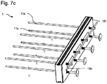
- the chaining system according to the invention may also include reinforcements 18 opposing the bending of at least some of said reinforcement rods.
- reinforcements 18 are for example illustrated on the figures 7a and 7b .
- Each of these reinforcements 18 passes through said layer of insulating material 12 to oppose the bending of at least one given reinforcement rod.
- this reinforcement 18 bears against the fixing piece 151 of the socket support while surrounding, via a tubular part of the reinforcement 18, a length portion of the reinforcement rod to be reinforced.
- this tubular reinforcing part 18 bears against the sleeve surrounding this reinforcement rod, but it is also possible that it bears directly against the reinforcement rod.
- These reinforcements 18 are preferably made of steel.
- Each of these reinforcements comprises two tubular parts interconnected by a veil, these reinforcements having an S shape.
- Each reinforcement 18 is a one-piece piece which can be made of metal, here steel or a composite material containing glass or carbon fibers and a binder for these fibers.
- Each of these reinforcements has an upper tubular part intended to surround a portion of one of the reinforcing rods of the upper row and a lower tubular part intended to surround a portion of one of the reinforcing rods of the lower row , the veil connecting these tubular parts rests flat against part 151 and passes through the thermal insulation.
- Each of these reinforcements 18 makes it possible to maintain parallelism between reinforcing rods of the upper and lower rows.
- the invention relates to a method of manufacturing a work 0 comprising first and second work elements 10, 20 and a chaining system 1 according to the invention, in which the first work element 10 is molded around a first part of the chaining system 1, then the layer of thermal insulating material 12 of the chaining system 1 is positioned facing the first element 10 thus molded before carrying out the molding of the second work element around the second portions P2 of the reinforcing rods 11a, 11b of the plurality of reinforcing rods.
- said first part of the chaining system around which said first work element 10 is molded comprises said at least one reinforcement rod support 15.
- the reinforcing rods 11a, 11b of the plurality of rods are assembled with said at least one reinforcing rod support 15 after molding said first work element 10 around said at least one reinforcing rod support 15.
- This method according to the invention is particularly advantageous because it makes it possible to mold the first work element 10 while the reinforcement rods 11a, 11b are not yet fixed to the reinforcement rod support 15, which makes it possible to simplify the molding operation.
- the mold M1 in which the first work element 10 is molded does not need to have special passages for the exit of the reinforcement rods 11a, 11b from the mold, these rods being put in place after molding of the work element 10 and removal of this mold M1.
- the reinforcement rods put in place according to the method of the invention are fixed, after hardening and demoulding of the first work element 10, by assembly on the reinforcement rod support 15 which is mechanically engaged in the first element of work 10.
- the method according to the invention also saves time during molding operations and a gain in positioning accuracy of the reinforcement rods 11a, 11b in the structure.
- said first part of the chaining system 1 around which said first work element 10 is molded comprises said plurality of sockets 152a, 152b assembled on the fixing part 151.
- this part 151 can be provided to be removed after molding of the first work element in order to be reused for the manufacture of another chaining (however this requires a management of the parts 151 and a need for cleaning and application of mold release grease).
- this fixing piece 151 is provided to remain in the structure 0 and it confers a sealing function around the reinforcement rods so as to limit the risk of corrosion of the rods.
- the layer of thermal insulating material 12 which is positioned facing the first element 10 is formed by at least one block of prefabricated insulating material comprising perforations 120 for the passage of reinforcement rods 11a, 11b through this layer 12.
- These perforations 120 are preferably spaced apart by a spacing pitch equal to a spacing pitch between the reinforcement rods of the plurality of reinforcement rods, this pitch being constant over the length of the chaining system.
- this system could not include a part 151 to support the sockets of the plurality of sockets.
- each sleeve of the plurality of sleeves could be fixed directly against the internal surface of the mold via an assembly element specific to each sleeve such as an element for bonding or magnetizing the sleeve. This embodiment is not preferred because it can generate positioning errors of the sockets with respect to each other.
- the reinforcement rods 11a, 11b are preferably transported with the layer of insulating material 12 but being outside this layer, against one of its longitudinal faces.
- the shell 125 of the layer of insulating material 12 may have wedging tabs adapted to wedge and carry the reinforcing rods 11a, 11b against the shell parallel to a longitudinal direction of the layer 12.
Landscapes
- Engineering & Computer Science (AREA)
- Architecture (AREA)
- Physics & Mathematics (AREA)
- Electromagnetism (AREA)
- Civil Engineering (AREA)
- Structural Engineering (AREA)
- Chain Conveyers (AREA)
- Organic Low-Molecular-Weight Compounds And Preparation Thereof (AREA)
- Wing Frames And Configurations (AREA)
Applications Claiming Priority (1)
| Application Number | Priority Date | Filing Date | Title |
|---|---|---|---|
| FR2102395A FR3120640B1 (fr) | 2021-03-11 | 2021-03-11 | Système de chaînage avec rupteur thermique |
Publications (4)
| Publication Number | Publication Date |
|---|---|
| EP4056777A2 true EP4056777A2 (de) | 2022-09-14 |
| EP4056777A3 EP4056777A3 (de) | 2023-01-04 |
| EP4056777B1 EP4056777B1 (de) | 2024-05-01 |
| EP4056777C0 EP4056777C0 (de) | 2024-05-01 |
Family
ID=75746864
Family Applications (1)
| Application Number | Title | Priority Date | Filing Date |
|---|---|---|---|
| EP22161718.6A Active EP4056777B1 (de) | 2021-03-11 | 2022-03-11 | Verkettungssystem mit thermischer trennung |
Country Status (2)
| Country | Link |
|---|---|
| EP (1) | EP4056777B1 (de) |
| FR (2) | FR3120640B1 (de) |
Family Cites Families (6)
| Publication number | Priority date | Publication date | Assignee | Title |
|---|---|---|---|---|
| CH676615A5 (de) * | 1988-04-22 | 1991-02-15 | Bau Box Ewiag | |
| CH691606A5 (de) * | 1996-11-08 | 2001-08-31 | Pecon Ag | Kragplattenanschlusselement. |
| DE29903589U1 (de) * | 1999-02-26 | 1999-05-20 | Schöck Bauteile GmbH, 76534 Baden-Baden | Bauelement zur Wärmedämmung |
| WO2001051730A1 (en) * | 2000-01-13 | 2001-07-19 | Dow Global Technologies Inc. | Reinforcing bars for concrete structures |
| FR2873727B1 (fr) * | 2004-07-29 | 2008-06-27 | Armatures Assemblees Mure S N | Procede pour limiter les ponts thermiques lors de l'edification de parois de construction mettant en oeuvre des armatures de reprise vissees |
| US8973317B2 (en) * | 2013-05-13 | 2015-03-10 | James Larkin | Thermal break for concrete slab edges and balconies |
-
2021
- 2021-03-11 FR FR2102395A patent/FR3120640B1/fr active Active
-
2022
- 2022-03-11 EP EP22161718.6A patent/EP4056777B1/de active Active
-
2023
- 2023-10-04 FR FR2310594A patent/FR3140388B1/fr active Active
Also Published As
| Publication number | Publication date |
|---|---|
| EP4056777B1 (de) | 2024-05-01 |
| FR3120640A1 (fr) | 2022-09-16 |
| EP4056777A3 (de) | 2023-01-04 |
| FR3140388A1 (fr) | 2024-04-05 |
| EP4056777C0 (de) | 2024-05-01 |
| FR3120640B1 (fr) | 2023-11-03 |
| FR3140388B1 (fr) | 2026-02-06 |
Similar Documents
| Publication | Publication Date | Title |
|---|---|---|
| WO2015015103A1 (fr) | Procede d'edification d'un ouvrage en elements prefabriques en beton et ouvrage associe | |
| EP4056777B1 (de) | Verkettungssystem mit thermischer trennung | |
| EP3205788A1 (de) | Isolierter konstruktionsblock mit dämmung zwischen zwei platten und haltestruktur für die platten | |
| WO2017017357A1 (fr) | Procede de fabrication d'un element de paroi d'un reservoir etanche et thermiquement isolant | |
| EP2868829B1 (de) | Verstärkungsverfahren eines Bauelements aus Holz durch den Zusammenbau eines nachgespannten Verstärkungsmoduls | |
| CH677250A5 (de) | ||
| EP1956156B1 (de) | Anschluss zur Verbindung von zwei Platten einer Mauer mit verlorener Verschalung | |
| EP3867140B1 (de) | Schwimmmodul einer schwimmenden struktur und verfahren zur verbindung solcher schwimmenden module | |
| FR3008116A1 (fr) | Procede, kit et bloc de construction | |
| FR2943701A1 (fr) | Procede de fabrication d'un panneau prefabrique destine a former une paroi isolante de batiment | |
| EP3992476A1 (de) | Abstandshalter und befestigungskit für aussenverkleidungen | |
| FR2539782A1 (fr) | Poutre sollicitee en flexion en beton precontraint ou en beton arme | |
| FR2912440A1 (fr) | Panneau prefabrique destine a former une paroi isolante d'un batiment,et procede de fabrication de ce panneau | |
| WO2015136194A1 (fr) | Barrette de renfort pour element de structure | |
| EP2837749A1 (de) | Herstellungsverfahren einer Verbundwand | |
| EP4276243B1 (de) | Verfahren zur lokalen übernahme der spannung eines vorspannkabels und system zur überbrückung eines vorspannkabels mit diesem verfahren | |
| FR3096699A1 (fr) | Procédé de construction à base de prédalle d’un plancher à rupture de pont thermique | |
| EP3763897A1 (de) | Hubanker für eine mauer mit integrierter schalung, und mauer mit integrierter schalung, die einen solchen hubanker umfasst | |
| FR2811002A1 (fr) | Procede et systeme de mise en traction d'un dispositif de renforcement de structure | |
| FR2739118A1 (fr) | Construction en bois munie d'une ame d'encastrement | |
| FR3107910A1 (fr) | Connecteurs pour relier entre elles des première et seconde parois d’un élément préfabriqué. | |
| WO2022074146A1 (fr) | Système de pont modulaire et son procédé de fabrication | |
| EP4301941A1 (de) | Strukturelle anordnung mit mehreren aneinander verbundenen und gespannten benachbarten blöcken | |
| FR3115844A3 (fr) | Cheville de maintien et kit de fixation pour parement extérieur | |
| FR3131591A1 (fr) | Procédé de fabrication d’un mur. |
Legal Events
| Date | Code | Title | Description |
|---|---|---|---|
| PUAI | Public reference made under article 153(3) epc to a published international application that has entered the european phase |
Free format text: ORIGINAL CODE: 0009012 |
|
| STAA | Information on the status of an ep patent application or granted ep patent |
Free format text: STATUS: THE APPLICATION HAS BEEN PUBLISHED |
|
| AK | Designated contracting states |
Kind code of ref document: A2 Designated state(s): AL AT BE BG CH CY CZ DE DK EE ES FI FR GB GR HR HU IE IS IT LI LT LU LV MC MK MT NL NO PL PT RO RS SE SI SK SM TR |
|
| PUAL | Search report despatched |
Free format text: ORIGINAL CODE: 0009013 |
|
| AK | Designated contracting states |
Kind code of ref document: A3 Designated state(s): AL AT BE BG CH CY CZ DE DK EE ES FI FR GB GR HR HU IE IS IT LI LT LU LV MC MK MT NL NO PL PT RO RS SE SI SK SM TR |
|
| RIC1 | Information provided on ipc code assigned before grant |
Ipc: E04C 5/07 20060101ALN20221129BHEP Ipc: E04B 5/32 20060101ALN20221129BHEP Ipc: E04B 1/76 20060101ALN20221129BHEP Ipc: E04B 1/00 20060101AFI20221129BHEP |
|
| STAA | Information on the status of an ep patent application or granted ep patent |
Free format text: STATUS: REQUEST FOR EXAMINATION WAS MADE |
|
| 17P | Request for examination filed |
Effective date: 20230703 |
|
| RAV | Requested validation state of the european patent: fee paid |
Extension state: TN Effective date: 20230703 Extension state: MA Effective date: 20230703 |
|
| RBV | Designated contracting states (corrected) |
Designated state(s): AL AT BE BG CH CY CZ DE DK EE ES FI FR GB GR HR HU IE IS IT LI LT LU LV MC MK MT NL NO PL PT RO RS SE SI SK SM TR |
|
| RIN1 | Information on inventor provided before grant (corrected) |
Inventor name: GUICHERD, JOSSELIN |
|
| GRAP | Despatch of communication of intention to grant a patent |
Free format text: ORIGINAL CODE: EPIDOSNIGR1 |
|
| STAA | Information on the status of an ep patent application or granted ep patent |
Free format text: STATUS: GRANT OF PATENT IS INTENDED |
|
| RIC1 | Information provided on ipc code assigned before grant |
Ipc: E04C 5/07 20060101ALN20231018BHEP Ipc: E04B 1/76 20060101ALN20231018BHEP Ipc: E04B 5/32 20060101ALI20231018BHEP Ipc: E04B 1/00 20060101AFI20231018BHEP |
|
| INTG | Intention to grant announced |
Effective date: 20231108 |
|
| GRAS | Grant fee paid |
Free format text: ORIGINAL CODE: EPIDOSNIGR3 |
|
| GRAA | (expected) grant |
Free format text: ORIGINAL CODE: 0009210 |
|
| STAA | Information on the status of an ep patent application or granted ep patent |
Free format text: STATUS: THE PATENT HAS BEEN GRANTED |
|
| AK | Designated contracting states |
Kind code of ref document: B1 Designated state(s): AL AT BE BG CH CY CZ DE DK EE ES FI FR GB GR HR HU IE IS IT LI LT LU LV MC MK MT NL NO PL PT RO RS SE SI SK SM TR |
|
| REG | Reference to a national code |
Ref country code: GB Ref legal event code: FG4D Free format text: NOT ENGLISH |
|
| REG | Reference to a national code |
Ref country code: CH Ref legal event code: EP |
|
| REG | Reference to a national code |
Ref country code: IE Ref legal event code: FG4D Free format text: LANGUAGE OF EP DOCUMENT: FRENCH |
|
| REG | Reference to a national code |
Ref country code: DE Ref legal event code: R096 Ref document number: 602022003116 Country of ref document: DE |
|
| U01 | Request for unitary effect filed |
Effective date: 20240531 |
|
| U07 | Unitary effect registered |
Designated state(s): AT BE BG DE DK EE FI FR IT LT LU LV MT NL PT SE SI Effective date: 20240611 |
|
| PG25 | Lapsed in a contracting state [announced via postgrant information from national office to epo] |
Ref country code: IS Free format text: LAPSE BECAUSE OF FAILURE TO SUBMIT A TRANSLATION OF THE DESCRIPTION OR TO PAY THE FEE WITHIN THE PRESCRIBED TIME-LIMIT Effective date: 20240901 |
|
| PG25 | Lapsed in a contracting state [announced via postgrant information from national office to epo] |
Ref country code: HR Free format text: LAPSE BECAUSE OF FAILURE TO SUBMIT A TRANSLATION OF THE DESCRIPTION OR TO PAY THE FEE WITHIN THE PRESCRIBED TIME-LIMIT Effective date: 20240501 |
|
| PG25 | Lapsed in a contracting state [announced via postgrant information from national office to epo] |
Ref country code: GR Free format text: LAPSE BECAUSE OF FAILURE TO SUBMIT A TRANSLATION OF THE DESCRIPTION OR TO PAY THE FEE WITHIN THE PRESCRIBED TIME-LIMIT Effective date: 20240802 |
|
| PG25 | Lapsed in a contracting state [announced via postgrant information from national office to epo] |
Ref country code: ES Free format text: LAPSE BECAUSE OF FAILURE TO SUBMIT A TRANSLATION OF THE DESCRIPTION OR TO PAY THE FEE WITHIN THE PRESCRIBED TIME-LIMIT Effective date: 20240501 |
|
| PG25 | Lapsed in a contracting state [announced via postgrant information from national office to epo] |
Ref country code: PL Free format text: LAPSE BECAUSE OF FAILURE TO SUBMIT A TRANSLATION OF THE DESCRIPTION OR TO PAY THE FEE WITHIN THE PRESCRIBED TIME-LIMIT Effective date: 20240501 |
|
| PG25 | Lapsed in a contracting state [announced via postgrant information from national office to epo] |
Ref country code: PL Free format text: LAPSE BECAUSE OF FAILURE TO SUBMIT A TRANSLATION OF THE DESCRIPTION OR TO PAY THE FEE WITHIN THE PRESCRIBED TIME-LIMIT Effective date: 20240501 Ref country code: NO Free format text: LAPSE BECAUSE OF FAILURE TO SUBMIT A TRANSLATION OF THE DESCRIPTION OR TO PAY THE FEE WITHIN THE PRESCRIBED TIME-LIMIT Effective date: 20240801 Ref country code: IS Free format text: LAPSE BECAUSE OF FAILURE TO SUBMIT A TRANSLATION OF THE DESCRIPTION OR TO PAY THE FEE WITHIN THE PRESCRIBED TIME-LIMIT Effective date: 20240901 Ref country code: HR Free format text: LAPSE BECAUSE OF FAILURE TO SUBMIT A TRANSLATION OF THE DESCRIPTION OR TO PAY THE FEE WITHIN THE PRESCRIBED TIME-LIMIT Effective date: 20240501 Ref country code: GR Free format text: LAPSE BECAUSE OF FAILURE TO SUBMIT A TRANSLATION OF THE DESCRIPTION OR TO PAY THE FEE WITHIN THE PRESCRIBED TIME-LIMIT Effective date: 20240802 Ref country code: ES Free format text: LAPSE BECAUSE OF FAILURE TO SUBMIT A TRANSLATION OF THE DESCRIPTION OR TO PAY THE FEE WITHIN THE PRESCRIBED TIME-LIMIT Effective date: 20240501 Ref country code: RS Free format text: LAPSE BECAUSE OF FAILURE TO SUBMIT A TRANSLATION OF THE DESCRIPTION OR TO PAY THE FEE WITHIN THE PRESCRIBED TIME-LIMIT Effective date: 20240801 |
|
| PG25 | Lapsed in a contracting state [announced via postgrant information from national office to epo] |
Ref country code: CZ Free format text: LAPSE BECAUSE OF FAILURE TO SUBMIT A TRANSLATION OF THE DESCRIPTION OR TO PAY THE FEE WITHIN THE PRESCRIBED TIME-LIMIT Effective date: 20240501 |
|
| PG25 | Lapsed in a contracting state [announced via postgrant information from national office to epo] |
Ref country code: RO Free format text: LAPSE BECAUSE OF FAILURE TO SUBMIT A TRANSLATION OF THE DESCRIPTION OR TO PAY THE FEE WITHIN THE PRESCRIBED TIME-LIMIT Effective date: 20240501 Ref country code: SK Free format text: LAPSE BECAUSE OF FAILURE TO SUBMIT A TRANSLATION OF THE DESCRIPTION OR TO PAY THE FEE WITHIN THE PRESCRIBED TIME-LIMIT Effective date: 20240501 |
|
| PG25 | Lapsed in a contracting state [announced via postgrant information from national office to epo] |
Ref country code: SM Free format text: LAPSE BECAUSE OF FAILURE TO SUBMIT A TRANSLATION OF THE DESCRIPTION OR TO PAY THE FEE WITHIN THE PRESCRIBED TIME-LIMIT Effective date: 20240501 |
|
| PG25 | Lapsed in a contracting state [announced via postgrant information from national office to epo] |
Ref country code: SM Free format text: LAPSE BECAUSE OF FAILURE TO SUBMIT A TRANSLATION OF THE DESCRIPTION OR TO PAY THE FEE WITHIN THE PRESCRIBED TIME-LIMIT Effective date: 20240501 Ref country code: SK Free format text: LAPSE BECAUSE OF FAILURE TO SUBMIT A TRANSLATION OF THE DESCRIPTION OR TO PAY THE FEE WITHIN THE PRESCRIBED TIME-LIMIT Effective date: 20240501 Ref country code: RO Free format text: LAPSE BECAUSE OF FAILURE TO SUBMIT A TRANSLATION OF THE DESCRIPTION OR TO PAY THE FEE WITHIN THE PRESCRIBED TIME-LIMIT Effective date: 20240501 Ref country code: CZ Free format text: LAPSE BECAUSE OF FAILURE TO SUBMIT A TRANSLATION OF THE DESCRIPTION OR TO PAY THE FEE WITHIN THE PRESCRIBED TIME-LIMIT Effective date: 20240501 |
|
| REG | Reference to a national code |
Ref country code: DE Ref legal event code: R097 Ref document number: 602022003116 Country of ref document: DE |
|
| PLBE | No opposition filed within time limit |
Free format text: ORIGINAL CODE: 0009261 |
|
| STAA | Information on the status of an ep patent application or granted ep patent |
Free format text: STATUS: NO OPPOSITION FILED WITHIN TIME LIMIT |
|
| 26N | No opposition filed |
Effective date: 20250204 |
|
| U20 | Renewal fee for the european patent with unitary effect paid |
Year of fee payment: 4 Effective date: 20250325 |
|
| PG25 | Lapsed in a contracting state [announced via postgrant information from national office to epo] |
Ref country code: MC Free format text: LAPSE BECAUSE OF FAILURE TO SUBMIT A TRANSLATION OF THE DESCRIPTION OR TO PAY THE FEE WITHIN THE PRESCRIBED TIME-LIMIT Effective date: 20240501 |
|
| REG | Reference to a national code |
Ref country code: CH Ref legal event code: H13 Free format text: ST27 STATUS EVENT CODE: U-0-0-H10-H13 (AS PROVIDED BY THE NATIONAL OFFICE) Effective date: 20251023 |
|
| PG25 | Lapsed in a contracting state [announced via postgrant information from national office to epo] |
Ref country code: CH Free format text: LAPSE BECAUSE OF NON-PAYMENT OF DUE FEES Effective date: 20250331 |
|
| PG25 | Lapsed in a contracting state [announced via postgrant information from national office to epo] |
Ref country code: IE Free format text: LAPSE BECAUSE OF NON-PAYMENT OF DUE FEES Effective date: 20250311 |
|
| VS25 | Lapsed in a validation state [announced via postgrant information from nat. office to epo] |
Ref country code: MA Free format text: FAILURE TO ELECT DOMICILE IN THE NATIONAL COUNTRY Effective date: 20240802 |
|
| VS25 | Lapsed in a validation state [announced via postgrant information from nat. office to epo] |
Ref country code: MA Free format text: LAPSE BECAUSE OF FAILURE TO SUBMIT A TRANSLATION OF THE DESCRIPTION OR TO PAY THE FEE WITHIN THE PRESCRIBED TIME-LIMIT Effective date: 20240501 |
|
| U20 | Renewal fee for the european patent with unitary effect paid |
Year of fee payment: 5 Effective date: 20260326 |