EP4056796B1 - System zur verwendung in einem fenster - Google Patents
System zur verwendung in einem fenster Download PDFInfo
- Publication number
- EP4056796B1 EP4056796B1 EP22159792.5A EP22159792A EP4056796B1 EP 4056796 B1 EP4056796 B1 EP 4056796B1 EP 22159792 A EP22159792 A EP 22159792A EP 4056796 B1 EP4056796 B1 EP 4056796B1
- Authority
- EP
- European Patent Office
- Prior art keywords
- cylinder
- knob
- cam control
- corner
- engagement
- Prior art date
- Legal status (The legal status is an assumption and is not a legal conclusion. Google has not performed a legal analysis and makes no representation as to the accuracy of the status listed.)
- Active
Links
Images

Classifications
-
- E—FIXED CONSTRUCTIONS
- E05—LOCKS; KEYS; WINDOW OR DOOR FITTINGS; SAFES
- E05C—BOLTS OR FASTENING DEVICES FOR WINGS, SPECIALLY FOR DOORS OR WINDOWS
- E05C9/00—Arrangements of simultaneously actuated bolts or other securing devices at well-separated positions on the same wing
- E05C9/24—Means for transmitting movements between vertical and horizontal sliding bars, rods or cables for the fastening of wings, e.g. corner guides
-
- E—FIXED CONSTRUCTIONS
- E05—LOCKS; KEYS; WINDOW OR DOOR FITTINGS; SAFES
- E05C—BOLTS OR FASTENING DEVICES FOR WINGS, SPECIALLY FOR DOORS OR WINDOWS
- E05C17/00—Devices for holding wings open; Devices for limiting opening of wings or for holding wings open by a movable member extending between frame and wing; Braking devices, stops or buffers, combined therewith
- E05C17/02—Devices for holding wings open; Devices for limiting opening of wings or for holding wings open by a movable member extending between frame and wing; Braking devices, stops or buffers, combined therewith by mechanical means
- E05C17/46—Devices for holding wings open; Devices for limiting opening of wings or for holding wings open by a movable member extending between frame and wing; Braking devices, stops or buffers, combined therewith by mechanical means in which the wing or a member fixed thereon is engaged by a movable fastening member in a fixed position; in which a movable fastening member mounted on the wing engages a stationary member
-
- E—FIXED CONSTRUCTIONS
- E05—LOCKS; KEYS; WINDOW OR DOOR FITTINGS; SAFES
- E05C—BOLTS OR FASTENING DEVICES FOR WINGS, SPECIALLY FOR DOORS OR WINDOWS
- E05C9/00—Arrangements of simultaneously actuated bolts or other securing devices at well-separated positions on the same wing
- E05C9/02—Arrangements of simultaneously actuated bolts or other securing devices at well-separated positions on the same wing with one sliding bar for fastening when moved in one direction and unfastening when moved in opposite direction; with two sliding bars moved in the same direction when fastening or unfastening
-
- E—FIXED CONSTRUCTIONS
- E05—LOCKS; KEYS; WINDOW OR DOOR FITTINGS; SAFES
- E05C—BOLTS OR FASTENING DEVICES FOR WINGS, SPECIALLY FOR DOORS OR WINDOWS
- E05C9/00—Arrangements of simultaneously actuated bolts or other securing devices at well-separated positions on the same wing
- E05C9/08—Arrangements of simultaneously actuated bolts or other securing devices at well-separated positions on the same wing with a rotary bar for actuating the fastening means
Definitions
- the invention relates to a system for use in a window which can be opened and comprises a corner and a brake which is activated upon rotation of a rod in the brake, the system comprising: a corner section having a first surface portion and a second surface portion positioned substantially perpendicular to each other and intended for embedding in a track in the window corner; a rotatable cylinder for engagement with the rod so as to enable it to activate the brake, which cylinder comprises a longitudinal center axis; at least one activation means which can push or pull a connection portion transferring a rotational movement to the cylinder, the connection portion comprises a knob adapted to a sliding engagement with a cam control of the cylinder adapted thereto which cam control and knob are mutually adapted in such a way that the cylinder rotates around its center axis when the knob is pulled in the longitudinal direction of the cylinder while the knob is engaged with the cam control and moved in same.
- An openable window is often made in a way that it can be locked in optional positions between its completely opened position and its closed position. This may be achieved with a hooklike engagement portion which is insertable in various holes depending on the user's desired opening degree of the window.
- the window can be locked in different positions by the user simply turning the handle also used to unlock the window.
- the handle activates a locking mechanism, and usually this is done in such a way that a movement of the handle causes a rod to rotate which is engaged in a brake mechanism activated by this rotation.
- the handle itself is normally positioned on (i) the lower horizontal strip of the window while the mechanism for activating the locking mechanism is positioned on (i) one of the vertical strips of the window.
- a fitting for a window has connecting rods guided behind sleeves that are fastened to a leaf e.g. window leaf, in a displaceable manner.
- a clamping device provided for fixing the leaf has a pivoting lever connected to a guiding carriage in a pivotable manner. The carriage is secured against displacement through rotation of a locking bar. The bar is attached to one of the rods over a deflection coupling. The coupling converts linear movement of the rod into a rotation movement of bar, where the coupling is held in a guide rail.
- a rotary output part of the espagnolette is connected to an angular motion transmission device via a rotary transmission shaft.
- said activation means (2) is flexible and can be displaced over the corner under elastic deformation and thereby push or pull the connection portion (3) transferring a rotational movement to the cylinder (4); that the cylinder (4) is held in a cylinder housing (8); • that the cylinder housing comprises one or more engagement means (9) for engagement with complementary engagement means (10) on one surface portion (20) of the corner section.
- knob and cam control is a simple and strong mechanical connection.
- the cylinder with cam control is mutually adapted to the connection portion and the knob in such a way that the knob engages with the cam control of the cylinder from the outer side of the cylinder and towards its central center axis.
- the cylinder is held in a cylinder housing and the connection portion comprises an elongated body held between cylinder housing and cylinder in such a way that the knob engages with the cam control of the cylinder from the outer side of the cylinder and towards its central center axis.
- the elongated body is consequently "locked” between these parts and therefore this construction/embodiment can withstand a greater load than constructions in which the elongated body is not locked and at the same time - in this embodiment - the torque applied to the cylinder is optimized as the knob is in engagement as far away as possible from the center axis of the cylinder.
- the cylinder housing is configured to comprise one or more engagement means for engagement with complementary engagement means on one surface portion of the corner section.
- the flexible activation means comprises a leaf spring which can be displaced over the corner under elastic deformation.
- a leaf spring allows large compressive/tractive forces and it can easily be bent around a corner.
- the leaf spring is therefore a simple and strong solution and as leaf springs are configured as an elongated "leaf” the "leaf” does not occupy much space when the system is to be installed in a window frame.
- the corner section comprises a guiding portion which holds the flexible activation means in a sliding engagement
- guiding portion comprises two flange like portions extending along the sides of the guiding portion and simultaneously configured in such a way that the flexible activation means is held behind these.
- the flange like portions holds the leaf spring in such a way that it is secured against deflection.
- the guide portion consequently ensures that the leaf spring can be manufactured slightly thinner than would be possible if it was not held by flange like portions.
- the thinner configuration furthermore has the advantage that the leaf spring is more easily deformed and therefore it is more easily bendable over the corner, resulting in an easy operation - on the part of users of the system.
- figure 1 a system 1 for a corner in a door, a window or another object which can be opened and held in a position between completely opened and completely closed.
- the system is to be inserted in a corner and for this it comprises a corner section with a first surface portion 20 and a second surface portion 30. These portions are positioned substantially perpendicular to each other and normally they are placed in a milled out track in the corner of the window or the door.
- the purpose of the system is to activate a brake in such a way that the window or the door can be held in positions between completely opened and completely closed.
- Systems of this type are normally coupled to the handle used by a user when a window is to be unlocked because thereby the user may with this handle also lock the window in optional positions.
- the coupling itself between the handle and the system takes place indirectly with the surface portion 30 shown to the left in figure 1 as it takes place through a coupling portion 31.
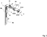
- the system is consequently to be used in a well-known construction of a window or a door in which a movement of the handle pushes or pulls the coupling portion 31 as indicated by the arrow m in figure 2 .
- the coupling portion 31 is connected to one end of a leaf spring 2 and in the embodiment shown this connection has been made by a riveted bolt 32, it may however naturally be made in other ways.
- the leaf spring 2 is mounted in a bent guide portion 7 behind two flanges 7a and 7b of the guide portion 7. The other end of the leaf spring 2 is through a track 22 in the first surface portion 20 connected to a connection portion 3 via a peg 21.
- the connection portion 3 comprises an elongated body 3a which at its outer end is provided with a knob 5 as shown to the right in the figure.
- the knob 5 is in engagement with a cam control 6 of a cylinder 4 mounted rotatably in a cylinder housing 8 which is fastened to the first surface portion 20.
- the cylinder 4 is mounted in the cylinder housing 8 so as to be able to rotate around its longitudinal axis c.
- the cam control may be configured as a track made in the side of the cylinder, however provided that the cylinder at least partially forms an annular elongated body the cam control may also be made in a way that the track - in the annular part of the cylinder - forms an opening extending from the outer side of the cylinder to its inner side.
- the cylinder housing 8 is provided with engagement means 9 insertable in openings 10 in the first surface portion 20 complementary hereto.
- these engagement means are made as flexible pieces of plate and in practice the fastening of the cylinder housing takes place by inserting the pieces of plate through the openings 10 and thereafter bending these towards the flange portion (as can be seen in figure 2 ).
- FIG 2 an assembled system according to the invention is shown and it is indicated by arrows that a movement m of the coupling portion 31 will propagate to the leaf spring 2 which moves through the corner and on to the connection portion 3 (not shown in figure 2 ) and its peg connection 21 which will move correspondingly m as shown at the top of figure 2 .
- this rotation is normally used to activate a brake in such a way that the window can be kept in a particular position.
- a brake can consequently be coupled to the cylinder and activated via the window handle.
- the knob 5 and the elongated body 3a may also be made in a way that the knob 5 engages with the cam control from the outer side of the cylinder or from the inner side of the cylinder.
- the knob engages with the cam control from the outer side of the cylinder. I.e. in such a way that the free end of the knob is located within the cylinder while the elongated body 3a is located on the outer side of the cylinder 4.
- the elongated body 3a is consequently "locked” between these parts and therefore this construction/embodiment can withstand a larger load than constructions in which the elongated body 3a is not locked and at the same time - in this embodiment - the torque applied to the cylinder 4 is optimized as the knob 5 grips as far away as possible from the center axis of the cylinder.
- the cylinder 4 activates a brake via a rod which is inserted in the cylinder and the two parts are normally designed mutually adapted in such a way that the rod cannot be rotated in the cylinder without the latter rotating as well.
- Such mechanisms are well-known and they may be made by configuring the parts with edges, such as square or hexagonal edges (such as e.g. umbraco or torx).
Landscapes
- Engineering & Computer Science (AREA)
- Mechanical Engineering (AREA)
- Window Of Vehicle (AREA)
Claims (5)
- System (1) zur Verwendung in einem Fenster, das geöffnet werden kann und eine Ecke und eine Bremse umfasst, die durch Drehung einer Stange in der Bremse aktiviert wird, wobei das System Folgendes umfasst:• einen Eckabschnitt mit einem ersten Oberflächenabschnitt (20) und einem zweiten Oberflächenabschnitt (30), die im Wesentlichen senkrecht zueinander angeordnet sind und zum Einbetten in eine Schiene in der Fensterecke vorgesehen sind;• einen drehbaren Zylinder (4) zum Eingreifen in die Stange, um es dieser zu ermöglichen, die Bremse zu betätigen, wobei der Zylinder (4) eine Längsmittelachse (c) umfasst;• mindestens ein Aktivierungsmittel (2), das einen Verbindungsabschnitt (3) drücken oder ziehen kann, der eine Drehbewegung auf den Zylinder (4) überträgt, wobei der Verbindungsabschnitt (3) einen Knopf (5) umfasst, der zu einem gleitenden Eingriff mit einer daran angepassten Nockensteuerung (6) des Zylinders (4) angepasst ist, wobei die Nockensteuerung (6) und der Knopf (5) so aneinander angepasst sind, dass sich der Zylinder (4) um seine Mittelachse (c) dreht, wenn der Knopf (5) in Längsrichtung des Zylinders (4) gezogen wird, während der Knopf (5) mit der Nockensteuerung (6) in Eingriff steht und in dieser bewegt wird, dadurch gekennzeichnet,• dass das Aktivierungsmittel (2) flexibel ist und unter elastischer Verformung über die Ecke verschoben werden kann und dadurch den Verbindungsabschnitt (3) drückt oder zieht und eine Drehbewegung auf den Zylinder (4) überträgt;• dass der Zylinder (4) in einem Zylindergehäuse (8) gehalten wird;• dass das Zylindergehäuse (8) ein oder mehrere Eingriffsmittel (9) zum Eingriff mit komplementären Eingriffsmitteln (10) an einem Oberflächenabschnitt (20) des Eckabschnitts umfasst.
- System nach Anspruch 1, dadurch gekennzeichnet, dass der Zylinder (4) mit Nockensteuerung (6) so an den Verbindungsabschnitt und den Knopf (5) angepasst ist, dass der Knopf (5) von der Außenseite des Zylinders (4) her und zu seiner zentralen Mittelachse hin mit der Nockensteuerung (6) des Zylinders (4) in Eingriff tritt.
- System nach einem der Ansprüche 1-2, dadurch gekennzeichnet, dass das flexible Aktivierungsmittel (2) mindestens eine Blattfeder umfasst, die unter elastischer Verformung über die Ecke verschoben werden kann.
- System nach Anspruch 3, dadurch gekennzeichnet, dass der Eckabschnitt einen Führungsabschnitt (7) umfasst, der das flexible Aktivierungsmittel (2) in einem Gleiteingriff hält, wobei der Führungsabschnitt (7) zwei flanschartige Abschnitte (7a, 7b) umfasst, die sich entlang der Seiten des Führungsabschnitts (7) erstrecken und gleichzeitig so konfiguriert sind, dass das flexible Aktivierungsmittel (2) hinter diesen gehalten wird.
- System nach den Ansprüchen 1-4, dadurch gekennzeichnet, dass der Zylinder (4) in einem Zylindergehäuse (8) gehalten wird und dass der Verbindungsabschnitt (3) einen länglichen Körper (3a) umfasst, der so zwischen Zylindergehäuse (8) und Zylinder (4) gehalten wird, dass der Knopf (5) von der Außenseite des Zylinders (4) her und zu seiner zentralen Mittelachse hin mit der Nockensteuerung (6) des Zylinders (4) in Eingriff tritt.
Applications Claiming Priority (2)
| Application Number | Priority Date | Filing Date | Title |
|---|---|---|---|
| DKPA202100240 | 2021-03-08 | ||
| DKPA202100285 | 2021-03-22 |
Publications (2)
| Publication Number | Publication Date |
|---|---|
| EP4056796A1 EP4056796A1 (de) | 2022-09-14 |
| EP4056796B1 true EP4056796B1 (de) | 2024-08-14 |
Family
ID=80785017
Family Applications (1)
| Application Number | Title | Priority Date | Filing Date |
|---|---|---|---|
| EP22159792.5A Active EP4056796B1 (de) | 2021-03-08 | 2022-03-02 | System zur verwendung in einem fenster |
Country Status (1)
| Country | Link |
|---|---|
| EP (1) | EP4056796B1 (de) |
Family Cites Families (4)
| Publication number | Priority date | Publication date | Assignee | Title |
|---|---|---|---|---|
| DE2941631C2 (de) * | 1979-10-13 | 1985-06-20 | Siegenia-Frank Kg, 5900 Siegen | Eckumlenkung für Treibstangenbeschläge |
| DE19834038C2 (de) * | 1998-07-29 | 2002-09-19 | Siegenia Frank Kg | Treibstangenbeschlag mit Eckumlenkung |
| EE200700018A (et) * | 2006-05-05 | 2007-12-17 | Scanfinn Oy | lekandemehhanism |
| DE102008049319B4 (de) * | 2008-09-29 | 2010-09-02 | Carl Fuhr Gmbh & Co. Kg | Beschlag für Fenster, Türen oder dergleichen |
-
2022
- 2022-03-02 EP EP22159792.5A patent/EP4056796B1/de active Active
Also Published As
| Publication number | Publication date |
|---|---|
| EP4056796A1 (de) | 2022-09-14 |
Similar Documents
| Publication | Publication Date | Title |
|---|---|---|
| CA2306427C (en) | Inner door handle for automobiles | |
| FI82287B (fi) | Doerrlaos. | |
| US20070051143A1 (en) | Door lock with controllable handle operation | |
| US11846122B2 (en) | Lift handle arrangement | |
| US4902057A (en) | Adjustable deadlatch | |
| JPH0545752B2 (de) | ||
| US20100045052A1 (en) | Near and remote controlled vehicle door lock | |
| KR101916103B1 (ko) | 잠금장치를 포함한 창호용 그립 손잡이 | |
| EP1153184A1 (de) | Griffkontrolle für ein einsteckschloss | |
| EP3219886B1 (de) | Anti-panikdruckstange mit antriebseinrichtung | |
| EP2224081A2 (de) | Verschluss für Schiebetür oder -tor | |
| KR101977369B1 (ko) | 도어 안전 잠금장치 | |
| EP3702560A1 (de) | Mechanismus zum betätigen eines autoschlüssels | |
| EP1383978B1 (de) | Verriegelungsanordnung | |
| US20200115937A1 (en) | Handle set engagement cartridge | |
| EP0731871B1 (de) | Treibstangenverschluss für ein fenster oder eine tuer | |
| KR102452891B1 (ko) | 창호용 잠금장치 | |
| EP4056796A1 (de) | System zur verwendung in einem fenster | |
| EP1819893B1 (de) | Kraftstellglied | |
| GB2185059A (en) | Multiple latch mechanism | |
| EP2985399B1 (de) | Griff für eine tür oder ein fenster mit zwei- oder drei-punkt-verriegelung | |
| KR102408051B1 (ko) | 미닫이 창호용 잠금시스템 | |
| CZ300655B6 (cs) | Blokovací úchyt, zejména pro motorová vozidla | |
| WO1996001356A1 (en) | Espagnolette fastening for windows or doors | |
| EP4491836B1 (de) | Griffrückführungsanordnung und griff für eine tür oder ein fenster |
Legal Events
| Date | Code | Title | Description |
|---|---|---|---|
| PUAI | Public reference made under article 153(3) epc to a published international application that has entered the european phase |
Free format text: ORIGINAL CODE: 0009012 |
|
| STAA | Information on the status of an ep patent application or granted ep patent |
Free format text: STATUS: THE APPLICATION HAS BEEN PUBLISHED |
|
| AK | Designated contracting states |
Kind code of ref document: A1 Designated state(s): AL AT BE BG CH CY CZ DE DK EE ES FI FR GB GR HR HU IE IS IT LI LT LU LV MC MK MT NL NO PL PT RO RS SE SI SK SM TR |
|
| STAA | Information on the status of an ep patent application or granted ep patent |
Free format text: STATUS: REQUEST FOR EXAMINATION WAS MADE |
|
| 17P | Request for examination filed |
Effective date: 20230314 |
|
| RBV | Designated contracting states (corrected) |
Designated state(s): AL AT BE BG CH CY CZ DE DK EE ES FI FR GB GR HR HU IE IS IT LI LT LU LV MC MK MT NL NO PL PT RO RS SE SI SK SM TR |
|
| STAA | Information on the status of an ep patent application or granted ep patent |
Free format text: STATUS: EXAMINATION IS IN PROGRESS |
|
| 17Q | First examination report despatched |
Effective date: 20230915 |
|
| GRAP | Despatch of communication of intention to grant a patent |
Free format text: ORIGINAL CODE: EPIDOSNIGR1 |
|
| STAA | Information on the status of an ep patent application or granted ep patent |
Free format text: STATUS: GRANT OF PATENT IS INTENDED |
|
| RIC1 | Information provided on ipc code assigned before grant |
Ipc: E05C 9/08 20060101ALN20240301BHEP Ipc: E05C 17/46 20060101ALI20240301BHEP Ipc: E05C 9/02 20060101ALI20240301BHEP Ipc: E05C 9/24 20060101AFI20240301BHEP |
|
| INTG | Intention to grant announced |
Effective date: 20240322 |
|
| GRAS | Grant fee paid |
Free format text: ORIGINAL CODE: EPIDOSNIGR3 |
|
| GRAA | (expected) grant |
Free format text: ORIGINAL CODE: 0009210 |
|
| STAA | Information on the status of an ep patent application or granted ep patent |
Free format text: STATUS: THE PATENT HAS BEEN GRANTED |
|
| AK | Designated contracting states |
Kind code of ref document: B1 Designated state(s): AL AT BE BG CH CY CZ DE DK EE ES FI FR GB GR HR HU IE IS IT LI LT LU LV MC MK MT NL NO PL PT RO RS SE SI SK SM TR |
|
| REG | Reference to a national code |
Ref country code: GB Ref legal event code: FG4D |
|
| REG | Reference to a national code |
Ref country code: CH Ref legal event code: EP |
|
| REG | Reference to a national code |
Ref country code: DE Ref legal event code: R096 Ref document number: 602022005245 Country of ref document: DE |
|
| REG | Reference to a national code |
Ref country code: IE Ref legal event code: FG4D |
|
| REG | Reference to a national code |
Ref country code: LT Ref legal event code: MG9D |
|
| REG | Reference to a national code |
Ref country code: NL Ref legal event code: MP Effective date: 20240814 |
|
| PG25 | Lapsed in a contracting state [announced via postgrant information from national office to epo] |
Ref country code: NO Free format text: LAPSE BECAUSE OF FAILURE TO SUBMIT A TRANSLATION OF THE DESCRIPTION OR TO PAY THE FEE WITHIN THE PRESCRIBED TIME-LIMIT Effective date: 20241114 |
|
| REG | Reference to a national code |
Ref country code: AT Ref legal event code: MK05 Ref document number: 1713445 Country of ref document: AT Kind code of ref document: T Effective date: 20240814 |
|
| PG25 | Lapsed in a contracting state [announced via postgrant information from national office to epo] |
Ref country code: NL Free format text: LAPSE BECAUSE OF FAILURE TO SUBMIT A TRANSLATION OF THE DESCRIPTION OR TO PAY THE FEE WITHIN THE PRESCRIBED TIME-LIMIT Effective date: 20240814 Ref country code: GR Free format text: LAPSE BECAUSE OF FAILURE TO SUBMIT A TRANSLATION OF THE DESCRIPTION OR TO PAY THE FEE WITHIN THE PRESCRIBED TIME-LIMIT Effective date: 20241115 Ref country code: PL Free format text: LAPSE BECAUSE OF FAILURE TO SUBMIT A TRANSLATION OF THE DESCRIPTION OR TO PAY THE FEE WITHIN THE PRESCRIBED TIME-LIMIT Effective date: 20240814 Ref country code: PT Free format text: LAPSE BECAUSE OF FAILURE TO SUBMIT A TRANSLATION OF THE DESCRIPTION OR TO PAY THE FEE WITHIN THE PRESCRIBED TIME-LIMIT Effective date: 20241216 Ref country code: FI Free format text: LAPSE BECAUSE OF FAILURE TO SUBMIT A TRANSLATION OF THE DESCRIPTION OR TO PAY THE FEE WITHIN THE PRESCRIBED TIME-LIMIT Effective date: 20240814 |
|
| PG25 | Lapsed in a contracting state [announced via postgrant information from national office to epo] |
Ref country code: BG Free format text: LAPSE BECAUSE OF FAILURE TO SUBMIT A TRANSLATION OF THE DESCRIPTION OR TO PAY THE FEE WITHIN THE PRESCRIBED TIME-LIMIT Effective date: 20240814 |
|
| PG25 | Lapsed in a contracting state [announced via postgrant information from national office to epo] |
Ref country code: LV Free format text: LAPSE BECAUSE OF FAILURE TO SUBMIT A TRANSLATION OF THE DESCRIPTION OR TO PAY THE FEE WITHIN THE PRESCRIBED TIME-LIMIT Effective date: 20240814 |
|
| PG25 | Lapsed in a contracting state [announced via postgrant information from national office to epo] |
Ref country code: AT Free format text: LAPSE BECAUSE OF FAILURE TO SUBMIT A TRANSLATION OF THE DESCRIPTION OR TO PAY THE FEE WITHIN THE PRESCRIBED TIME-LIMIT Effective date: 20240814 Ref country code: IS Free format text: LAPSE BECAUSE OF FAILURE TO SUBMIT A TRANSLATION OF THE DESCRIPTION OR TO PAY THE FEE WITHIN THE PRESCRIBED TIME-LIMIT Effective date: 20241214 |
|
| PG25 | Lapsed in a contracting state [announced via postgrant information from national office to epo] |
Ref country code: HR Free format text: LAPSE BECAUSE OF FAILURE TO SUBMIT A TRANSLATION OF THE DESCRIPTION OR TO PAY THE FEE WITHIN THE PRESCRIBED TIME-LIMIT Effective date: 20240814 |
|
| PG25 | Lapsed in a contracting state [announced via postgrant information from national office to epo] |
Ref country code: RS Free format text: LAPSE BECAUSE OF FAILURE TO SUBMIT A TRANSLATION OF THE DESCRIPTION OR TO PAY THE FEE WITHIN THE PRESCRIBED TIME-LIMIT Effective date: 20241114 Ref country code: ES Free format text: LAPSE BECAUSE OF FAILURE TO SUBMIT A TRANSLATION OF THE DESCRIPTION OR TO PAY THE FEE WITHIN THE PRESCRIBED TIME-LIMIT Effective date: 20240814 |
|
| PG25 | Lapsed in a contracting state [announced via postgrant information from national office to epo] |
Ref country code: RS Free format text: LAPSE BECAUSE OF FAILURE TO SUBMIT A TRANSLATION OF THE DESCRIPTION OR TO PAY THE FEE WITHIN THE PRESCRIBED TIME-LIMIT Effective date: 20241114 Ref country code: PT Free format text: LAPSE BECAUSE OF FAILURE TO SUBMIT A TRANSLATION OF THE DESCRIPTION OR TO PAY THE FEE WITHIN THE PRESCRIBED TIME-LIMIT Effective date: 20241216 Ref country code: PL Free format text: LAPSE BECAUSE OF FAILURE TO SUBMIT A TRANSLATION OF THE DESCRIPTION OR TO PAY THE FEE WITHIN THE PRESCRIBED TIME-LIMIT Effective date: 20240814 Ref country code: NO Free format text: LAPSE BECAUSE OF FAILURE TO SUBMIT A TRANSLATION OF THE DESCRIPTION OR TO PAY THE FEE WITHIN THE PRESCRIBED TIME-LIMIT Effective date: 20241114 Ref country code: NL Free format text: LAPSE BECAUSE OF FAILURE TO SUBMIT A TRANSLATION OF THE DESCRIPTION OR TO PAY THE FEE WITHIN THE PRESCRIBED TIME-LIMIT Effective date: 20240814 Ref country code: LV Free format text: LAPSE BECAUSE OF FAILURE TO SUBMIT A TRANSLATION OF THE DESCRIPTION OR TO PAY THE FEE WITHIN THE PRESCRIBED TIME-LIMIT Effective date: 20240814 Ref country code: IS Free format text: LAPSE BECAUSE OF FAILURE TO SUBMIT A TRANSLATION OF THE DESCRIPTION OR TO PAY THE FEE WITHIN THE PRESCRIBED TIME-LIMIT Effective date: 20241214 Ref country code: HR Free format text: LAPSE BECAUSE OF FAILURE TO SUBMIT A TRANSLATION OF THE DESCRIPTION OR TO PAY THE FEE WITHIN THE PRESCRIBED TIME-LIMIT Effective date: 20240814 Ref country code: GR Free format text: LAPSE BECAUSE OF FAILURE TO SUBMIT A TRANSLATION OF THE DESCRIPTION OR TO PAY THE FEE WITHIN THE PRESCRIBED TIME-LIMIT Effective date: 20241115 Ref country code: FI Free format text: LAPSE BECAUSE OF FAILURE TO SUBMIT A TRANSLATION OF THE DESCRIPTION OR TO PAY THE FEE WITHIN THE PRESCRIBED TIME-LIMIT Effective date: 20240814 Ref country code: ES Free format text: LAPSE BECAUSE OF FAILURE TO SUBMIT A TRANSLATION OF THE DESCRIPTION OR TO PAY THE FEE WITHIN THE PRESCRIBED TIME-LIMIT Effective date: 20240814 Ref country code: BG Free format text: LAPSE BECAUSE OF FAILURE TO SUBMIT A TRANSLATION OF THE DESCRIPTION OR TO PAY THE FEE WITHIN THE PRESCRIBED TIME-LIMIT Effective date: 20240814 Ref country code: AT Free format text: LAPSE BECAUSE OF FAILURE TO SUBMIT A TRANSLATION OF THE DESCRIPTION OR TO PAY THE FEE WITHIN THE PRESCRIBED TIME-LIMIT Effective date: 20240814 |
|
| PG25 | Lapsed in a contracting state [announced via postgrant information from national office to epo] |
Ref country code: DK Free format text: LAPSE BECAUSE OF FAILURE TO SUBMIT A TRANSLATION OF THE DESCRIPTION OR TO PAY THE FEE WITHIN THE PRESCRIBED TIME-LIMIT Effective date: 20240814 Ref country code: RO Free format text: LAPSE BECAUSE OF FAILURE TO SUBMIT A TRANSLATION OF THE DESCRIPTION OR TO PAY THE FEE WITHIN THE PRESCRIBED TIME-LIMIT Effective date: 20240814 Ref country code: SM Free format text: LAPSE BECAUSE OF FAILURE TO SUBMIT A TRANSLATION OF THE DESCRIPTION OR TO PAY THE FEE WITHIN THE PRESCRIBED TIME-LIMIT Effective date: 20240814 |
|
| PG25 | Lapsed in a contracting state [announced via postgrant information from national office to epo] |
Ref country code: EE Free format text: LAPSE BECAUSE OF FAILURE TO SUBMIT A TRANSLATION OF THE DESCRIPTION OR TO PAY THE FEE WITHIN THE PRESCRIBED TIME-LIMIT Effective date: 20240814 |
|
| PG25 | Lapsed in a contracting state [announced via postgrant information from national office to epo] |
Ref country code: CZ Free format text: LAPSE BECAUSE OF FAILURE TO SUBMIT A TRANSLATION OF THE DESCRIPTION OR TO PAY THE FEE WITHIN THE PRESCRIBED TIME-LIMIT Effective date: 20240814 |
|
| PG25 | Lapsed in a contracting state [announced via postgrant information from national office to epo] |
Ref country code: IT Free format text: LAPSE BECAUSE OF FAILURE TO SUBMIT A TRANSLATION OF THE DESCRIPTION OR TO PAY THE FEE WITHIN THE PRESCRIBED TIME-LIMIT Effective date: 20240814 Ref country code: SK Free format text: LAPSE BECAUSE OF FAILURE TO SUBMIT A TRANSLATION OF THE DESCRIPTION OR TO PAY THE FEE WITHIN THE PRESCRIBED TIME-LIMIT Effective date: 20240814 |
|
| REG | Reference to a national code |
Ref country code: DE Ref legal event code: R097 Ref document number: 602022005245 Country of ref document: DE |
|
| PLBE | No opposition filed within time limit |
Free format text: ORIGINAL CODE: 0009261 |
|
| STAA | Information on the status of an ep patent application or granted ep patent |
Free format text: STATUS: NO OPPOSITION FILED WITHIN TIME LIMIT |
|
| 26N | No opposition filed |
Effective date: 20250515 |
|
| PG25 | Lapsed in a contracting state [announced via postgrant information from national office to epo] |
Ref country code: SE Free format text: LAPSE BECAUSE OF FAILURE TO SUBMIT A TRANSLATION OF THE DESCRIPTION OR TO PAY THE FEE WITHIN THE PRESCRIBED TIME-LIMIT Effective date: 20240814 |
|
| REG | Reference to a national code |
Ref country code: DE Ref legal event code: R119 Ref document number: 602022005245 Country of ref document: DE |
|
| PG25 | Lapsed in a contracting state [announced via postgrant information from national office to epo] |
Ref country code: MC Free format text: LAPSE BECAUSE OF FAILURE TO SUBMIT A TRANSLATION OF THE DESCRIPTION OR TO PAY THE FEE WITHIN THE PRESCRIBED TIME-LIMIT Effective date: 20240814 |
|
| REG | Reference to a national code |
Ref country code: CH Ref legal event code: H13 Free format text: ST27 STATUS EVENT CODE: U-0-0-H10-H13 (AS PROVIDED BY THE NATIONAL OFFICE) Effective date: 20251023 |
|
| PG25 | Lapsed in a contracting state [announced via postgrant information from national office to epo] |
Ref country code: LU Free format text: LAPSE BECAUSE OF NON-PAYMENT OF DUE FEES Effective date: 20250302 |
|
| REG | Reference to a national code |
Ref country code: BE Ref legal event code: MM Effective date: 20250331 |
|
| PG25 | Lapsed in a contracting state [announced via postgrant information from national office to epo] |
Ref country code: DE Free format text: LAPSE BECAUSE OF NON-PAYMENT OF DUE FEES Effective date: 20251001 |
|
| PG25 | Lapsed in a contracting state [announced via postgrant information from national office to epo] |
Ref country code: FR Free format text: LAPSE BECAUSE OF NON-PAYMENT OF DUE FEES Effective date: 20250331 |
|
| PG25 | Lapsed in a contracting state [announced via postgrant information from national office to epo] |
Ref country code: BE Free format text: LAPSE BECAUSE OF NON-PAYMENT OF DUE FEES Effective date: 20250331 |
|
| PG25 | Lapsed in a contracting state [announced via postgrant information from national office to epo] |
Ref country code: CH Free format text: LAPSE BECAUSE OF NON-PAYMENT OF DUE FEES Effective date: 20250331 |
|
| PG25 | Lapsed in a contracting state [announced via postgrant information from national office to epo] |
Ref country code: IE Free format text: LAPSE BECAUSE OF NON-PAYMENT OF DUE FEES Effective date: 20250302 |
|
| PG25 | Lapsed in a contracting state [announced via postgrant information from national office to epo] |
Ref country code: CY Free format text: LAPSE BECAUSE OF FAILURE TO SUBMIT A TRANSLATION OF THE DESCRIPTION OR TO PAY THE FEE WITHIN THE PRESCRIBED TIME-LIMIT Effective date: 20240814 |
|
| PG25 | Lapsed in a contracting state [announced via postgrant information from national office to epo] |
Ref country code: LT Free format text: LAPSE BECAUSE OF FAILURE TO SUBMIT A TRANSLATION OF THE DESCRIPTION OR TO PAY THE FEE WITHIN THE PRESCRIBED TIME-LIMIT Effective date: 20240814 |
|
| PG25 | Lapsed in a contracting state [announced via postgrant information from national office to epo] |
Ref country code: TR Free format text: LAPSE BECAUSE OF FAILURE TO SUBMIT A TRANSLATION OF THE DESCRIPTION OR TO PAY THE FEE WITHIN THE PRESCRIBED TIME-LIMIT Effective date: 20240814 |