EP4056818A1 - Dispositif de chauffage d'un système d'échappement d'un moteur à combustion interne - Google Patents
Dispositif de chauffage d'un système d'échappement d'un moteur à combustion interne Download PDFInfo
- Publication number
- EP4056818A1 EP4056818A1 EP22159026.8A EP22159026A EP4056818A1 EP 4056818 A1 EP4056818 A1 EP 4056818A1 EP 22159026 A EP22159026 A EP 22159026A EP 4056818 A1 EP4056818 A1 EP 4056818A1
- Authority
- EP
- European Patent Office
- Prior art keywords
- fuel
- heating device
- tubular body
- fuel injector
- injector
- Prior art date
- Legal status (The legal status is an assumption and is not a legal conclusion. Google has not performed a legal analysis and makes no representation as to the accuracy of the status listed.)
- Granted
Links
Images





Classifications
-
- F—MECHANICAL ENGINEERING; LIGHTING; HEATING; WEAPONS; BLASTING
- F01—MACHINES OR ENGINES IN GENERAL; ENGINE PLANTS IN GENERAL; STEAM ENGINES
- F01N—GAS-FLOW SILENCERS OR EXHAUST APPARATUS FOR MACHINES OR ENGINES IN GENERAL; GAS-FLOW SILENCERS OR EXHAUST APPARATUS FOR INTERNAL-COMBUSTION ENGINES
- F01N3/00—Exhaust or silencing apparatus having means for purifying, rendering innocuous, or otherwise treating exhaust
- F01N3/02—Exhaust or silencing apparatus having means for purifying, rendering innocuous, or otherwise treating exhaust for cooling, or for removing solid constituents of, exhaust
- F01N3/021—Exhaust or silencing apparatus having means for purifying, rendering innocuous, or otherwise treating exhaust for cooling, or for removing solid constituents of, exhaust by means of filters
- F01N3/023—Exhaust or silencing apparatus having means for purifying, rendering innocuous, or otherwise treating exhaust for cooling, or for removing solid constituents of, exhaust by means of filters using means for regenerating the filters, e.g. by burning trapped particles
- F01N3/025—Exhaust or silencing apparatus having means for purifying, rendering innocuous, or otherwise treating exhaust for cooling, or for removing solid constituents of, exhaust by means of filters using means for regenerating the filters, e.g. by burning trapped particles using fuel burner or by adding fuel to exhaust
- F01N3/0253—Exhaust or silencing apparatus having means for purifying, rendering innocuous, or otherwise treating exhaust for cooling, or for removing solid constituents of, exhaust by means of filters using means for regenerating the filters, e.g. by burning trapped particles using fuel burner or by adding fuel to exhaust adding fuel to exhaust gases
- F01N3/0256—Exhaust or silencing apparatus having means for purifying, rendering innocuous, or otherwise treating exhaust for cooling, or for removing solid constituents of, exhaust by means of filters using means for regenerating the filters, e.g. by burning trapped particles using fuel burner or by adding fuel to exhaust adding fuel to exhaust gases the fuel being ignited by electrical means
-
- F—MECHANICAL ENGINEERING; LIGHTING; HEATING; WEAPONS; BLASTING
- F01—MACHINES OR ENGINES IN GENERAL; ENGINE PLANTS IN GENERAL; STEAM ENGINES
- F01N—GAS-FLOW SILENCERS OR EXHAUST APPARATUS FOR MACHINES OR ENGINES IN GENERAL; GAS-FLOW SILENCERS OR EXHAUST APPARATUS FOR INTERNAL-COMBUSTION ENGINES
- F01N3/00—Exhaust or silencing apparatus having means for purifying, rendering innocuous, or otherwise treating exhaust
- F01N3/08—Exhaust or silencing apparatus having means for purifying, rendering innocuous, or otherwise treating exhaust for rendering innocuous
- F01N3/10—Exhaust or silencing apparatus having means for purifying, rendering innocuous, or otherwise treating exhaust for rendering innocuous by thermal or catalytic conversion of noxious components of exhaust
- F01N3/18—Exhaust or silencing apparatus having means for purifying, rendering innocuous, or otherwise treating exhaust for rendering innocuous by thermal or catalytic conversion of noxious components of exhaust characterised by methods of operation; Control
- F01N3/20—Exhaust or silencing apparatus having means for purifying, rendering innocuous, or otherwise treating exhaust for rendering innocuous by thermal or catalytic conversion of noxious components of exhaust characterised by methods of operation; Control specially adapted for catalytic conversion
- F01N3/2006—Periodically heating or cooling catalytic reactors, e.g. at cold starting or overheating
- F01N3/2033—Periodically heating or cooling catalytic reactors, e.g. at cold starting or overheating using a fuel burner or introducing fuel into exhaust duct
-
- F—MECHANICAL ENGINEERING; LIGHTING; HEATING; WEAPONS; BLASTING
- F01—MACHINES OR ENGINES IN GENERAL; ENGINE PLANTS IN GENERAL; STEAM ENGINES
- F01N—GAS-FLOW SILENCERS OR EXHAUST APPARATUS FOR MACHINES OR ENGINES IN GENERAL; GAS-FLOW SILENCERS OR EXHAUST APPARATUS FOR INTERNAL-COMBUSTION ENGINES
- F01N2240/00—Combination or association of two or more different exhaust treating devices, or of at least one such device with an auxiliary device, not covered by indexing codes F01N2230/00 or F01N2250/00, one of the devices being
- F01N2240/14—Combination or association of two or more different exhaust treating devices, or of at least one such device with an auxiliary device, not covered by indexing codes F01N2230/00 or F01N2250/00, one of the devices being a fuel burner
-
- F—MECHANICAL ENGINEERING; LIGHTING; HEATING; WEAPONS; BLASTING
- F01—MACHINES OR ENGINES IN GENERAL; ENGINE PLANTS IN GENERAL; STEAM ENGINES
- F01N—GAS-FLOW SILENCERS OR EXHAUST APPARATUS FOR MACHINES OR ENGINES IN GENERAL; GAS-FLOW SILENCERS OR EXHAUST APPARATUS FOR INTERNAL-COMBUSTION ENGINES
- F01N2240/00—Combination or association of two or more different exhaust treating devices, or of at least one such device with an auxiliary device, not covered by indexing codes F01N2230/00 or F01N2250/00, one of the devices being
- F01N2240/20—Combination or association of two or more different exhaust treating devices, or of at least one such device with an auxiliary device, not covered by indexing codes F01N2230/00 or F01N2250/00, one of the devices being a flow director or deflector
-
- F—MECHANICAL ENGINEERING; LIGHTING; HEATING; WEAPONS; BLASTING
- F01—MACHINES OR ENGINES IN GENERAL; ENGINE PLANTS IN GENERAL; STEAM ENGINES
- F01N—GAS-FLOW SILENCERS OR EXHAUST APPARATUS FOR MACHINES OR ENGINES IN GENERAL; GAS-FLOW SILENCERS OR EXHAUST APPARATUS FOR INTERNAL-COMBUSTION ENGINES
- F01N2260/00—Exhaust treating devices having provisions not otherwise provided for
- F01N2260/04—Exhaust treating devices having provisions not otherwise provided for for regeneration or reactivation, e.g. of catalyst
-
- F—MECHANICAL ENGINEERING; LIGHTING; HEATING; WEAPONS; BLASTING
- F01—MACHINES OR ENGINES IN GENERAL; ENGINE PLANTS IN GENERAL; STEAM ENGINES
- F01N—GAS-FLOW SILENCERS OR EXHAUST APPARATUS FOR MACHINES OR ENGINES IN GENERAL; GAS-FLOW SILENCERS OR EXHAUST APPARATUS FOR INTERNAL-COMBUSTION ENGINES
- F01N2470/00—Structure or shape of exhaust gas passages, pipes or tubes
- F01N2470/02—Tubes being perforated
- F01N2470/04—Tubes being perforated characterised by shape, disposition or dimensions of apertures
-
- F—MECHANICAL ENGINEERING; LIGHTING; HEATING; WEAPONS; BLASTING
- F01—MACHINES OR ENGINES IN GENERAL; ENGINE PLANTS IN GENERAL; STEAM ENGINES
- F01N—GAS-FLOW SILENCERS OR EXHAUST APPARATUS FOR MACHINES OR ENGINES IN GENERAL; GAS-FLOW SILENCERS OR EXHAUST APPARATUS FOR INTERNAL-COMBUSTION ENGINES
- F01N2470/00—Structure or shape of exhaust gas passages, pipes or tubes
- F01N2470/08—Exhaust gas passages being formed between the walls of an outer shell and an inner chamber
-
- F—MECHANICAL ENGINEERING; LIGHTING; HEATING; WEAPONS; BLASTING
- F01—MACHINES OR ENGINES IN GENERAL; ENGINE PLANTS IN GENERAL; STEAM ENGINES
- F01N—GAS-FLOW SILENCERS OR EXHAUST APPARATUS FOR MACHINES OR ENGINES IN GENERAL; GAS-FLOW SILENCERS OR EXHAUST APPARATUS FOR INTERNAL-COMBUSTION ENGINES
- F01N2560/00—Exhaust systems with means for detecting or measuring exhaust gas components or characteristics
- F01N2560/06—Exhaust systems with means for detecting or measuring exhaust gas components or characteristics the means being a temperature sensor
-
- F—MECHANICAL ENGINEERING; LIGHTING; HEATING; WEAPONS; BLASTING
- F01—MACHINES OR ENGINES IN GENERAL; ENGINE PLANTS IN GENERAL; STEAM ENGINES
- F01N—GAS-FLOW SILENCERS OR EXHAUST APPARATUS FOR MACHINES OR ENGINES IN GENERAL; GAS-FLOW SILENCERS OR EXHAUST APPARATUS FOR INTERNAL-COMBUSTION ENGINES
- F01N2610/00—Adding substances to exhaust gases
- F01N2610/03—Adding substances to exhaust gases the substance being hydrocarbons, e.g. engine fuel
-
- F—MECHANICAL ENGINEERING; LIGHTING; HEATING; WEAPONS; BLASTING
- F01—MACHINES OR ENGINES IN GENERAL; ENGINE PLANTS IN GENERAL; STEAM ENGINES
- F01N—GAS-FLOW SILENCERS OR EXHAUST APPARATUS FOR MACHINES OR ENGINES IN GENERAL; GAS-FLOW SILENCERS OR EXHAUST APPARATUS FOR INTERNAL-COMBUSTION ENGINES
- F01N2610/00—Adding substances to exhaust gases
- F01N2610/14—Arrangements for the supply of substances, e.g. conduits
- F01N2610/1453—Sprayers or atomisers; Arrangement thereof in the exhaust apparatus
-
- Y—GENERAL TAGGING OF NEW TECHNOLOGICAL DEVELOPMENTS; GENERAL TAGGING OF CROSS-SECTIONAL TECHNOLOGIES SPANNING OVER SEVERAL SECTIONS OF THE IPC; TECHNICAL SUBJECTS COVERED BY FORMER USPC CROSS-REFERENCE ART COLLECTIONS [XRACs] AND DIGESTS
- Y02—TECHNOLOGIES OR APPLICATIONS FOR MITIGATION OR ADAPTATION AGAINST CLIMATE CHANGE
- Y02T—CLIMATE CHANGE MITIGATION TECHNOLOGIES RELATED TO TRANSPORTATION
- Y02T10/00—Road transport of goods or passengers
- Y02T10/10—Internal combustion engine [ICE] based vehicles
- Y02T10/12—Improving ICE efficiencies
Definitions
- This invention relates to a heating device for an exhaust system of an internal combustion engine.
- An exhaust system of an internal combustion engine comprises an exhaust duct along which at least one exhaust gas treatment device, for gases coming from the internal combustion engine, is installed; in particular, it always includes a (oxidation or reduction) catalytic converter to which a particulate filter can be added.
- the catalytic converter In order to operate (i.e., to carry out catalytic conversion), the catalytic converter needs to operate at a relatively high operating temperature (a modern catalytic converter operates at temperatures close to even 800°C) since the chemical conversion reactions of unburned hydrocarbons, nitrogen oxides, and carbon monoxide into carbon dioxide, water, and nitrogen only occur once the operating temperature has been reached.
- the temperature of the catalytic converter remains, for a relatively long time (even some minutes in winter and during a city route along which the internal combustion engine always runs at the minimum, or almost) far below the operating temperature.
- the polluting emissions coming out are high because the purification effect of the catalytic converter is null or it is, at least, very ineffective.
- the patents EP0631039A1 , WO2012139801A1 , and US8006487B2 propose installing a heating device along the exhaust duct, which, by burning fuel, generates a (very) hot air flow flowing through the catalytic converter.
- the heating device comprises a combustion chamber that is connected at the outlet to the exhaust duct (immediately upstream of the catalytic converter) and is connected at the inlet to a fan that generates an air flow flowing through the combustion chamber.
- a fuel injector which injects fuel that is mixed with air
- a spark plug which cyclically strikes sparks to ignite the air-fuel mixture so as to obtain the combustion heating the air, are also arranged.
- the patent US20110289906A1 describes a system for controlling the temperature of an exhaust flow of an internal combustion engine upstream of an exhaust gas post-treatment device.
- the purpose of this invention is to provide a heating device for an exhaust system of an internal combustion engine, which makes it possible to obtain, in all operating conditions, complete combustion of the fuel (i.e., without injecting unburned fuel into the exhaust duct) and, in addition, which is easy and inexpensive to produce.
- a heating device for an exhaust system of an internal combustion engine is provided, according to what is claimed in the attached claims.
- reference number 1 denotes, as a whole, an exhaust system of an internal combustion engine 2.
- the exhaust system 1 comprises an exhaust duct 3, which originates from an exhaust manifold of the internal combustion engine 2 and ends in a silencer 4, from which exhaust gases are released into the atmosphere.
- an exhaust gas treatment device 5 for gases coming from the internal combustion engine, is installed; in particular, it always includes a (oxidation or reduction) catalytic converter to which a particulate filter can be added.
- the catalytic converter In order to operate (i.e., to carry out catalytic conversion), the catalytic converter needs to operate at a relatively high operating temperature (a modern catalytic converter operates at temperatures close to even 800°C) since the chemical conversion reactions of unburned hydrocarbons, nitrogen oxides, and carbon monoxide into carbon dioxide, water, and nitrogen only occur once the operating temperature has been reached.
- the exhaust system 1 comprises a heating device 6 that, by burning fuel, generates a (very) hot air flow passing through the treatment device 5.
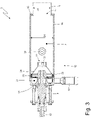
- the heating device 6 comprises a combustion chamber 7 that is connected at the outlet to the exhaust duct 3 (immediately upstream of the treatment device 5) and is connected at the inlet to a fan 8 (i.e. to an air pump) that generates an air flow crossing the combustion chamber 7; in the combustion chamber 7, a fuel injector 9, which injects fuel that is mixed with air, and a spark plug 10, which cyclically strikes sparks to ignite the air-fuel mixture so as to obtain combustion that heats the air, are arranged.
- the combustion chamber 7 of the heating device 6 ends in an outlet duct 11 that is engaged in the exhaust duct 3 (immediately upstream of the treatment device 5).
- the heating device 6 comprises a tubular body 12 (for example, cylindrical in shape and having a circular or elliptical cross-section) having a longitudinal axis 13; the tubular body 12 is delimited, at its two ends, by two base walls 14 and 15, which are opposite to each other, and is delimited, on the side, by a side wall 16 that connects the two base walls 14 and 15 together.
- the base wall 14 has a central hole to house the fuel injector 9 that is mounted coaxially to the tubular body 12 (i.e., coaxially to the longitudinal axis 13); in other words, the fuel injector 9 is mounted through the base wall 14 of the tubular body 12 to inject fuel into the combustion chamber 7.
- the base wall 15 has a central hole to engage with the outlet duct 11 ending in the exhaust duct 3; in other words, the base wall 15 has an outlet opening 17 for hot air from the combustion chamber 7 from which the outlet duct 11 originates.
- one inlet opening 18 is formed that is connected to the fan 8 via an inlet duct 19 (illustrated in Figures 1 and 3 ) to receive an air flow that is directed into the combustion chamber 7 and mixes with the fuel injected by the fuel injector 9.
- the air enters the inlet opening 18 with a flow oriented tangentially (in relation to the tubular body 12), i.e., the inlet duct 19 is oriented tangentially (in relation to the tubular body 12).
- a check valve 20 is arranged only allowing air to flow towards the combustion chamber 7 (i.e., entering the tubular body 12).
- the check valve 20 is preferably passive (i.e., it does not comprise electric, hydraulic, or pneumatic actuators that generate movement), is controlled under pressure, and only opens when pressure upstream of the check valve 20 is greater than the pressure downstream of the check valve 20.
- the check valve 20 functions to prevent exhaust gases from going back up until they leave the inlet opening 18 and, thus, from dispersing into the environment without passing through the treatment device 5.
- the check valve 20 may be assembled upstream along the outlet duct 11, for example, at the outlet opening 17; in this case, the check valve 20 only allows an air flow leaving the combustion chamber 7 (leaving the tubular body 12) towards the exhaust duct 3, i.e., it prevents a flow of exhaust gases from the exhaust duct 3 towards the combustion chamber 7 (entering the tubular body 12).
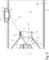
- the heating device 6 comprises a feeding channel 21 that receives air from the inlet opening 18, surrounds an end portion of the fuel injector 9, and ends in a nozzle 22, which is arranged around an injection point of the fuel injector 9 (i.e., around a nose of the fuel injector 9 from which fuel comes out).
- the spark plug 10 is assembled through the side wall 16 of the tubular body 12 to trigger the combustion of a mix of air and fuel that is generated due to the effect of mixing air, which enters the tubular body 12 from the inlet opening 18 and is injected into the combustion chamber 7 by the nozzle 22 of the feeding channel 21, and fuel, which is injected into the combustion chamber 7 by the fuel injector 9.
- the side wall 16 of the tubular body 12 has a through hole oriented radially (i.e., perpendicularly to the longitudinal axis 13) inside of which the spark plug 10 (which is obviously oriented radially) is fixed (i.e., screwed).
- the heating device 6 comprises a static mixer 23 (i.e., without moving parts), which is shaped like an annulus, is arranged along the feeding channel 21, and around the fuel injector 9, and is configured to generate turbulence, in particular a (rotary) swirling motion, in the air flowing towards the nozzle 22.
- the static mixer 23 is configured to generate a (rotary) swirling motion in the air flowing towards the nozzle 22 that has a certain rotation direction around the longitudinal axis 13 (i.e., a clockwise direction or anticlockwise direction around the longitudinal axis 13).
- the static mixer 23 is configured to generate a (rotary) swirling motion in the air flowing towards the nozzle 22 that has an anticlockwise direction looking from the base wall 15 (i.e., a clockwise direction looking from the base wall 14).
- the feeding channel 21 downstream of the static mixer 23, has a cross-section that progressively diminishes so that it determines an increase in the air's speed.
- the feeding channel 21 downstream of the static mixer 23, has an initial portion having a constant cross-section, an intermediate portion having a progressively diminishing cross-section, and a final portion having a constant cross-section up until the nozzle 22.
- the feeding channel 21 is delimited, on the outside, by an outer tubular body 24 (at least partially conical) and is delimited, on the inside, by an inner tubular body 25 (at least partially conical) surrounding the fuel injector 9 and containing, inside, the fuel injector 9 (i.e., it acts as a container for the end part of the fuel injector 9).
- the feeding channel 21 is defined between the inner tubular body 25 and the outer tubular body 24.
- the two tubular bodies 24 and 25 alternate conical portions (i.e., which have a converging form that progressively decreases in size along the longitudinal axis 13) with cylindrical portions (i.e., which have a shape with a constant size along the longitudinal axis 13); preferably, the end part of the inner tubular body 25 converges and tapers (i.e., it progressively reduces its size towards the nozzle 22) while the end part of the outer tubular body 24 has a cylindrical form.
- the air enters the feeding channel 21 with a flow oriented tangentially so as to have a (rotary) swirling progression that is successively increased by the action of the static mixer 23 and encourages its mixing with the fuel that is injected by the fuel injector 9.
- the injection of the comburent air inside the combustion chamber 7 through a duct tangentially directed to the combustion chamber 7 makes it possible to give a circular motion to the comburent air flow (additionally emphasised by the presence of the static mixer 23) so as to optimise the air/fuel mixing inside the combustion chamber 7.
- the fuel injector 9 is configured to spray at least 80% (and preferably at least 90-95%) of the fuel against an inner surface 26 of the feeding channel 21.
- the fuel injector 9 does not direct the fuel directly outside the feeding channel 21, but, instead, directs the fuel against the inner surface 26 of the feeding channel 21 so that the fuel that comes out of the fuel injector 9 first hits the inner surface 26 before exiting the feeding channel 21 through the nozzle 22.
- the impact of the fuel against the inner surface 26 makes it possible to very effectively pulverise the fuel drops emitted by the fuel injector 9 and, in this way, the mixing of fuel with air, which flows along the feeding channel 21, is markedly improved.
- An improvement in the mixing of air and fuel ensures an optimal combustion and, above all, complete combustion of the fuel, avoiding, thus, that part of the unburned fuel could leave the combustion chamber 7.
- the fuel injector 9 is configured to emit a fuel spray (jet) 27 having a conical shape hollow at the centre, i.e., which has a cross-section that is shaped like an annulus wherein the fuel is concentrated around the edges.
- a fuel spray (jet) 27 having a conical shape hollow at the centre, i.e., which has a cross-section that is shaped like an annulus wherein the fuel is concentrated around the edges.
- an outer surface of the fuel spray 27 has an opening angle ⁇ of approximately 70° (for example, ranging between 65° and 75°) and an inner surface of the fuel spray 27 has an opening angle ⁇ of approximately 50° (for example, ranging between 45° and 55°) .
- the fuel injector 9 generates a fuel spray 27 having a conical shape (with the vertex of the cone arranged near the injection nozzle) and having, in the centre, a hole (i.e., an area without fuel), which is also conical (with the vertex of the cone arranged near the injection nozzle).
- the fuel spray 27 generated by the fuel injector 9 has the shape of a conical skirt due to the effect of the central hole, i.e., it has an internally hollow conical shape.
- the fuel spray 27 generated by the fuel injector 9 has the shape of a conical skirt (i.e., it has an internally hollow shape), it is meant that the large majority of the fuel coming out of the fuel injector 9 is distributed in the space inside a conical skirt, but a small (residual) part of the fuel may be distributed differently.
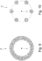
- the fuel spray 27 coming out of the fuel injector 9 may have a more symmetrical distribution around the longitudinal axis 13 (as illustrated in Figure 9 ) i.e., a less symmetrical distribution around the longitudinal axis 13 (as illustrated in Figure 10 ).
- the fuel spray 27 coming out of the fuel injector 9 has the shape illustrated in Figure 9 when the fuel injector 9 is a "swirl" injector, while the fuel spray 27 coming out of the fuel injector 9 has the shape illustrated in Figure 10 when the fuel injector 9 is a "multi hole” injector (in Figure 10 , there is a “multi hole” fuel injector 9 with six outlet holes, but the number of outlet holes could be different).
- the fuel injector 9 is a "swirl" injector, i.e., it gives the injected fuel a rotary swirling motion (i.e., a swirling motion in which the fuel rotates around the longitudinal axis 13 of the tubular body 12); the rotation direction that the fuel injector 9 gives the fuel is of the "swirl” type and concords with (i.e., is equal to) the rotation direction that the static mixer 23 gives.
- the feeding channel 21 is delimited, on the outside, by the outer tubular body 24 (having the inner surface 26 of the feeding channel 21) and is delimited, on the inside, by the inner tubular body 25, which surrounds the fuel injector 9 and contains, on the inside, the fuel injector 9.
- the outer tubular body 24 comprises a conical portion 28 that reduces in size towards the nozzle 22; in addition, according to a preferred embodiment illustrated in the attached figures, the outer tubular body 24 also comprises a cylindrical portion 29 that is arranged downstream of the conical portion 28 and ends in the nozzle 22. According to a different embodiment not illustrated, the outer tubular body 24 does not have a cylindrical portion 29 and, thus, only comprises the conical portion 28. According to an additional embodiment not illustrated, the cylindrical portion 29 could be replaced by an additional conical portion that tapers (converges) less than the tapering (convergence) of the conical portion 28.
- the fuel injector 9 is configured to spray at least part of the fuel against the cylindrical portion 29 (or against the additional conical portion) of the outer tubular body 24; in particular, the fuel injector 9 is configured to spray the majority (almost all) the fuel against the cylindrical portion 29 (or against the additional conical portion) of the outer tubular body 24.
- the fuel injector 9 is configured to spray at least part of the fuel against the cylindrical portion 29 (or against the additional conical portion) of the outer tubular body 24 and at least part of the fuel against the conical portion 28 of the outer tubular body 24; for example, the fuel injector 9 is configured to spray approximately half of the fuel against the conical portion 28 of the outer tubular body 24 and approximately half of the fuel against the cylindrical portion 29 (or against the additional conical portion) of the outer tubular body 24.
- the fuel injector 9 is configured to spray at least part of the fuel against the conical portion 28 of the outer tubular body 24; in particular, the fuel injector 9 is configured to spray the majority (almost all) the fuel against the conical portion 28 of the outer tubular body 24.
- an axial distance X (i.e. measured along the longitudinal axis 13 of the tubular body 12) between the nose of the fuel injector 9 from which the fuel comes out (i.e. the injection point of the fuel injector 9) and a longitudinal axis 30 of the spark plug 10 ranges between 33% and 100% of an inner diameter D1 of the tubular body 12 (i.e. of the diameter D1 of the combustion chamber 7); preferably, the axial distance X ranges between 50% and 100% of the inner diameter D1 of the tubular body 12 and, in particular, the axial distance X ranges between 60% and 90% of the inner diameter D1 of the tubular body 12.
- the tubular body 12 has a circular cross-section and, thus, there are no doubts regarding how the inner diameter D1 of the tubular body 12 is measured in order to evaluate the axial distance X; if, on the other hand, the tubular body 12 has an elliptical cross-section, then the greatest dimension would be considered as the inner diameter D1 of the tubular body 12 in order to evaluate the axial distance X.
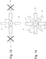
- the spark plug 10 has a single inner electrode 31 and a single outer electrode 32; according to variants illustrated in Figures 13 and 14 , the spark plug 10 has a single inner electrode 31 and two outer electrodes 32 ( Figure 13 ) or a single inner electrode 31 and four outer electrodes 32 ( Figure 14 ); according to an additional variant not illustrated, there could be three outer electrodes 32.
- the outer tubular body 24 has a through opening 33 (i.e., a slit) through which the nose of the fuel injector 9, from which the fuel comes out (i.e., the injection point of the fuel injector 9), "sees” the electrodes 31 and 32 of the spark plug 10. Thanks to the presence of the through opening 33, a limited part 34 of the fuel spray 27 emitted by the fuel injector 9, does not hit the outer tubular body 24, but flows through the outer tubular body 24 in order to directly reach the electrodes 31 and 32 of the spark plug 10.
- a through opening 33 i.e., a slit
- the limited part 34 of the fuel spray 27 directly "wets" the electrodes 31 and 32 of the spark plug 10 to create, around the electrodes 31 and 32 of the spark plug 10, a localised excess of fuel (i.e., a locally richer mix) that encourages flame ignition and, thus, encourages the flame's quick propagation to all the rest of the mix.
- a localised excess of fuel i.e., a locally richer mix
- the fuel injector 9 is configured to spray at least part of the fuel against the outer tubular body 24, and the outer tubular body 24 has a through opening 33 through which a limited part 34 of the fuel spray 27 emitted by the fuel injector 9, instead of hitting the outer tubular body 24, flows through the outer tubular body 24 in order to reach the electrodes 31 and 32 of the spark plug 10.
- the static mixer 23 is configured to generate, in the air flowing towards the nozzle 22, a (rotary) swirling motion that has a certain rotation direction around the longitudinal axis 13 of the tubular body 12.
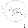
- the through opening 33 is moved circumferentially in the opposite direction to the rotation direction of the air given by the static mixer 23 in relation to an ideal line connecting an injection point of the injector 9 with the electrodes 31 and 32 of the spark plug 10.
- the through opening 33 is arranged spatially "in advance” to compensate for the rotary motion component given by the static mixer 23 (to which one can also add the action of the "swirl" fuel injector 9) so that the limited part 34 of the fuel spray 27, which flows through the outer tubular body 24 passing into the through opening 33, effectively reaches (i.e., a maximum part thereof) the electrodes 31 and 32 of the spark plug 10.
- the through opening 33 is arranged circumferentially "in advance” in relation to the axial alignment between the injection point of the injector 9 and the electrodes 31 and 32 of the spark plug 10 in order to compensate for the fuel's circumferential motion component.
- a middle plane of the through opening 33 forms an advance angle ⁇ other than zero ranging generally between 5° and 30°, and is preferably 15°, with an ideal line that connects the injection point of the injector 9 with the electrodes 31 and 32 of the spark plug 10.
- the through opening 33 is arranged along the ideal line that connects an injection point of the injector 9 with the electrodes 31 and 32 of the spark plug 10 (i.e., the advance angle ⁇ is null).
- the through opening 33 is shaped like a slit (i.e., it has an elongated shape wherein one dimension is greater than the other) and is oriented axially; as a result, the through opening 33 has a circumferential dimension that is smaller than its axial dimension (the circumferential dimension is approximately 50-70% of the axial dimension).
- the through opening 33 is shaped like a slit (i.e., it has an elongated shape wherein one dimension is greater than the other) and is oriented transversely (circumferentially); as a result, the through opening 33 has a circumferential dimension that is greater than its axial dimension (the circumferential dimension is approximately 40-65% of the axial dimension). In this embodiment, preferably, the circumferential dimension of the through opening 33 angularly ranges between 30° and 60°.
- the outlet duct 11 has an initial portion that is directly connected to the outlet opening 17 of the tubular body 12, has the same shape (i.e., the same type of cross-section) as the tubular body 12, is coaxial to the tubular body 12, and has an inner diameter D2 that is smaller than the inner diameter D1 of the tubular body 12.
- the ratio between the inner diameter D1 of the tubular body 12 and the inner diameter D2 of the initial portion of the outlet duct 11 ranges from 1.2 to 2, and is preferably 1.35.
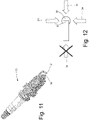
- the outer electrode 32 (or the outer electrodes 32) of the spark plug 10 is oriented so that it does not block (intercept) the limited part 34 of the fuel spray 27 advancing towards the inner electrode 31.
- the outer electrode 32 (or the outer electrodes 32) of the spark plug 10 is oriented so that it does not place the inner electrode 31 in shadow (screen it) in relation to the limited part 34 of the fuel spray 27.
- the spark that is generated between the two electrodes 31 and 32 is not in the shadow of (screened by) the outer electrode 32 in relation to the limited part 34 of the fuel spray 27.
- the fuel spray 27 emitted by the fuel injector 9 is perfectly symmetrical in relation to the longitudinal axis 13 of the tubular body 12 (and of the fuel injector 9); in other words, the longitudinal axis 13 of the tubular body 12 coincides with a central symmetry axis 35 of the fuel spray 27.
- the fuel spray 27 emitted by the fuel injector 9 is asymmetrical in relation to the longitudinal axis 13 of the tubular body 12 (and of the fuel injector 9) and, thus, the fuel spray 27 is tilted towards the electrodes 31 and 32 of the spark plug 10; in other words, the central symmetry axis 35 of the fuel spray 27 forms an angle ⁇ (other than zero) with the longitudinal axis 13 of the tubular body 12.
- the central symmetry axis 35 of the fuel spray 27 is tilted towards the electrodes 31 and 32 of the spark plug 10 to form the angle ⁇ that has a width ranging between 5° and 20°, preferably approximately 13-15°, with the longitudinal axis 13 of the tubular body 12. Tilting the fuel spray 27 towards the electrodes 31 and 32 of the spark plug 10 makes it possible to create, around the electrodes 31 and 32 of the spark plug 10, a localised excess of fuel (i.e., a locally richer mix) that encourages flame ignition and, thus, encourages the flame's quick propagation to all the rest of the mix.
- a localised excess of fuel i.e., a locally richer mix
- the heating device 6 comprises a control unit 36 (schematically illustrated in Figure 1 ), which is configured to control the whole operation of the heating device 6, i.e., to drive the fan 8, the injector 9, and the spark plug 10, in a coordinated fashion to achieve, in the most efficient and effective way possible, the desired goal (i.e., to quickly heat the treatment device 5 without damaging the heating device 5 due to excessive temperatures).
- a control unit 36 (schematically illustrated in Figure 1 ), which is configured to control the whole operation of the heating device 6, i.e., to drive the fan 8, the injector 9, and the spark plug 10, in a coordinated fashion to achieve, in the most efficient and effective way possible, the desired goal (i.e., to quickly heat the treatment device 5 without damaging the heating device 5 due to excessive temperatures).
- the heating device 6 comprises a temperature sensor 37 that is arranged along the outlet duct 11 in order to measure the temperature of the hot air flowing through the outlet duct 11.
- the heating device 6 comprises a temperature sensor 38 that is arranged along the outlet duct 3 downstream of the engagement point of the outlet duct 11 (and upstream of the treatment device 5) in order to measure the temperature of the mix of exhaust gases and hot air flowing through the exhaust duct 3.
- the control unit 36 uses the temperature sensor 37 or 38 readings to control (potentially in feedback) the combustion in the combustion chamber 7 so as to quickly heat the treatment device 5 without damaging the treatment device 5 due to excessive temperatures.
- the heating device 6 described above has numerous advantages.
- the heating device 6 described above makes it possible to obtain, in all operating conditions (particularly when a large quantity of fuel is injected to develop a large amount of heat), complete combustion of the fuel (i.e., without injecting unburned fuel into the exhaust duct 3) thanks to an optimal mixing between comburent air, injected by the nozzle 22 of the feeding channel 21, and fuel, injected by the fuel injector 9.
- the heating device 6 described above has great thermal power in relation to its overall dimensions; i.e., though it is relatively small, the heating device 6 described above makes it possible to generate great thermal power.
- the heating device 6 described above is simple and inexpensive to produce, since it is composed of few parts with simple shapes that are easy to join via welding and standard assembly.
Landscapes
- Engineering & Computer Science (AREA)
- Chemical & Material Sciences (AREA)
- Combustion & Propulsion (AREA)
- Mechanical Engineering (AREA)
- General Engineering & Computer Science (AREA)
- Chemical Kinetics & Catalysis (AREA)
- Health & Medical Sciences (AREA)
- Toxicology (AREA)
- Ignition Installations For Internal Combustion Engines (AREA)
- Fuel-Injection Apparatus (AREA)
Applications Claiming Priority (1)
| Application Number | Priority Date | Filing Date | Title |
|---|---|---|---|
| IT202100004577 | 2021-02-26 |
Publications (2)
| Publication Number | Publication Date |
|---|---|
| EP4056818A1 true EP4056818A1 (fr) | 2022-09-14 |
| EP4056818B1 EP4056818B1 (fr) | 2023-11-22 |
Family
ID=75937001
Family Applications (1)
| Application Number | Title | Priority Date | Filing Date |
|---|---|---|---|
| EP22159026.8A Active EP4056818B1 (fr) | 2021-02-26 | 2022-02-25 | Dispositif de chauffage d'un système d'échappement d'un moteur à combustion interne |
Country Status (1)
| Country | Link |
|---|---|
| EP (1) | EP4056818B1 (fr) |
Cited By (2)
| Publication number | Priority date | Publication date | Assignee | Title |
|---|---|---|---|---|
| EP4019748B1 (fr) * | 2020-12-23 | 2023-12-06 | Marelli Europe S.p.A. | Dispositif de chauffage d'un système d'échappement d'un moteur à combustion interne |
| WO2024104671A1 (fr) * | 2022-11-14 | 2024-05-23 | Robert Bosch Gmbh | Unité de brûleur dans un conduit d'échappement d'un moteur à combustion interne |
Citations (10)
| Publication number | Priority date | Publication date | Assignee | Title |
|---|---|---|---|---|
| US4571938A (en) * | 1982-08-27 | 1986-02-25 | Mazda Motor Corporation | Exhaust gas cleaning device for diesel engines |
| EP0590699A1 (fr) * | 1992-08-28 | 1994-04-06 | General Motors Corporation | Brûleur pour échauffement de gaz d'échappement |
| EP0631039A1 (fr) | 1993-06-09 | 1994-12-28 | Firma J. Eberspächer | Brûleur pour réchauffer rapidement et de façon indépendante du moteur un catalyseur d'échappement |
| JP2005180371A (ja) * | 2003-12-22 | 2005-07-07 | Bosch Automotive Systems Corp | 排気後処理装置用補助装置 |
| US8006487B2 (en) | 2006-12-19 | 2011-08-30 | J. Eberspaecher Gmbh & Co. Kg | Exhaust system for an internal combustion engine |
| EP2387656A1 (fr) * | 2009-01-15 | 2011-11-23 | Toyota Jidosha Kabushiki Kaisha | Dispositif de commande des gaz d'échappement d'un moteur à combustion interne |
| US20110289906A1 (en) | 2009-04-27 | 2011-12-01 | Nicholas Morley | Miniature Regeneration Unit |
| EP2466207A2 (fr) * | 2010-12-17 | 2012-06-20 | General Electric Company | Buse de combustible à double orifice d'atomisation de carburant |
| WO2012139801A1 (fr) | 2011-04-15 | 2012-10-18 | Robert Bosch Gmbh | Dispositif et procédé de chauffage des gaz d'échappement d'un moteur à combustion interne |
| EP4036384A1 (fr) * | 2021-01-29 | 2022-08-03 | Marelli Europe S.p.A. | Dispositif de chauffage d'un système d'échappement d'un moteur à combustion interne |
-
2022
- 2022-02-25 EP EP22159026.8A patent/EP4056818B1/fr active Active
Patent Citations (10)
| Publication number | Priority date | Publication date | Assignee | Title |
|---|---|---|---|---|
| US4571938A (en) * | 1982-08-27 | 1986-02-25 | Mazda Motor Corporation | Exhaust gas cleaning device for diesel engines |
| EP0590699A1 (fr) * | 1992-08-28 | 1994-04-06 | General Motors Corporation | Brûleur pour échauffement de gaz d'échappement |
| EP0631039A1 (fr) | 1993-06-09 | 1994-12-28 | Firma J. Eberspächer | Brûleur pour réchauffer rapidement et de façon indépendante du moteur un catalyseur d'échappement |
| JP2005180371A (ja) * | 2003-12-22 | 2005-07-07 | Bosch Automotive Systems Corp | 排気後処理装置用補助装置 |
| US8006487B2 (en) | 2006-12-19 | 2011-08-30 | J. Eberspaecher Gmbh & Co. Kg | Exhaust system for an internal combustion engine |
| EP2387656A1 (fr) * | 2009-01-15 | 2011-11-23 | Toyota Jidosha Kabushiki Kaisha | Dispositif de commande des gaz d'échappement d'un moteur à combustion interne |
| US20110289906A1 (en) | 2009-04-27 | 2011-12-01 | Nicholas Morley | Miniature Regeneration Unit |
| EP2466207A2 (fr) * | 2010-12-17 | 2012-06-20 | General Electric Company | Buse de combustible à double orifice d'atomisation de carburant |
| WO2012139801A1 (fr) | 2011-04-15 | 2012-10-18 | Robert Bosch Gmbh | Dispositif et procédé de chauffage des gaz d'échappement d'un moteur à combustion interne |
| EP4036384A1 (fr) * | 2021-01-29 | 2022-08-03 | Marelli Europe S.p.A. | Dispositif de chauffage d'un système d'échappement d'un moteur à combustion interne |
Cited By (2)
| Publication number | Priority date | Publication date | Assignee | Title |
|---|---|---|---|---|
| EP4019748B1 (fr) * | 2020-12-23 | 2023-12-06 | Marelli Europe S.p.A. | Dispositif de chauffage d'un système d'échappement d'un moteur à combustion interne |
| WO2024104671A1 (fr) * | 2022-11-14 | 2024-05-23 | Robert Bosch Gmbh | Unité de brûleur dans un conduit d'échappement d'un moteur à combustion interne |
Also Published As
| Publication number | Publication date |
|---|---|
| EP4056818B1 (fr) | 2023-11-22 |
Similar Documents
| Publication | Publication Date | Title |
|---|---|---|
| EP2239506B1 (fr) | Injecteur direct de prémélange | |
| US11674427B2 (en) | Heating device for an exhaust system of an internal combustion engine | |
| JP6196868B2 (ja) | 燃料ノズルとその組立方法 | |
| EP0617779B1 (fr) | Buse de combustion a faible niveau d'emissions s'utilisant sur un moteur de turbine a gaz | |
| CN104685297A (zh) | 火焰片燃烧器穹顶 | |
| EP4056818B1 (fr) | Dispositif de chauffage d'un système d'échappement d'un moteur à combustion interne | |
| JP3878980B2 (ja) | 燃焼装置用の燃料噴射装置 | |
| EP0639255B1 (fr) | Bruleur | |
| EP4036384B1 (fr) | Dispositif de chauffage d'un système d'échappement d'un moteur à combustion interne | |
| EP3339738B1 (fr) | Turbine comprenant une chambre de combustion de recirculation de gaz combustible | |
| EP4036383B1 (fr) | Dispositif de chauffage d'un système d'échappement d'un moteur à combustion interne | |
| EP4148241B1 (fr) | Dispositif de chauffage pour un système d'échappement d'un moteur à combustion interne | |
| CA2154452A1 (fr) | Injecteur de carburant a structure double et a injection d'eau | |
| JP3901663B2 (ja) | 急速混合燃料噴射弁及び低NOx燃焼器 | |
| US12338761B2 (en) | Heating device for an exhaust system of an internal combustion engine | |
| RU2852321C1 (ru) | Камера сгорания газотурбинного двигателя | |
| IT202100023672A1 (it) | Dispositivo riscaldatore per un sistema di scarico di un motore a combustione interna | |
| IT202100001892A1 (it) | Dispositivo riscaldatore per un sistema di scarico di un motore a combustione interna | |
| CN102414514A (zh) | 预混合燃烧器 |
Legal Events
| Date | Code | Title | Description |
|---|---|---|---|
| PUAI | Public reference made under article 153(3) epc to a published international application that has entered the european phase |
Free format text: ORIGINAL CODE: 0009012 |
|
| STAA | Information on the status of an ep patent application or granted ep patent |
Free format text: STATUS: THE APPLICATION HAS BEEN PUBLISHED |
|
| AK | Designated contracting states |
Kind code of ref document: A1 Designated state(s): AL AT BE BG CH CY CZ DE DK EE ES FI FR GB GR HR HU IE IS IT LI LT LU LV MC MK MT NL NO PL PT RO RS SE SI SK SM TR |
|
| STAA | Information on the status of an ep patent application or granted ep patent |
Free format text: STATUS: REQUEST FOR EXAMINATION WAS MADE |
|
| 17P | Request for examination filed |
Effective date: 20230203 |
|
| RBV | Designated contracting states (corrected) |
Designated state(s): AL AT BE BG CH CY CZ DE DK EE ES FI FR GB GR HR HU IE IS IT LI LT LU LV MC MK MT NL NO PL PT RO RS SE SI SK SM TR |
|
| GRAP | Despatch of communication of intention to grant a patent |
Free format text: ORIGINAL CODE: EPIDOSNIGR1 |
|
| STAA | Information on the status of an ep patent application or granted ep patent |
Free format text: STATUS: GRANT OF PATENT IS INTENDED |
|
| INTG | Intention to grant announced |
Effective date: 20230613 |
|
| GRAS | Grant fee paid |
Free format text: ORIGINAL CODE: EPIDOSNIGR3 |
|
| GRAA | (expected) grant |
Free format text: ORIGINAL CODE: 0009210 |
|
| STAA | Information on the status of an ep patent application or granted ep patent |
Free format text: STATUS: THE PATENT HAS BEEN GRANTED |
|
| AK | Designated contracting states |
Kind code of ref document: B1 Designated state(s): AL AT BE BG CH CY CZ DE DK EE ES FI FR GB GR HR HU IE IS IT LI LT LU LV MC MK MT NL NO PL PT RO RS SE SI SK SM TR |
|
| REG | Reference to a national code |
Ref country code: GB Ref legal event code: FG4D |
|
| REG | Reference to a national code |
Ref country code: CH Ref legal event code: EP |
|
| REG | Reference to a national code |
Ref country code: DE Ref legal event code: R096 Ref document number: 602022001044 Country of ref document: DE |
|
| REG | Reference to a national code |
Ref country code: IE Ref legal event code: FG4D |
|
| REG | Reference to a national code |
Ref country code: LT Ref legal event code: MG9D |
|
| REG | Reference to a national code |
Ref country code: NL Ref legal event code: MP Effective date: 20231122 |
|
| PG25 | Lapsed in a contracting state [announced via postgrant information from national office to epo] |
Ref country code: GR Free format text: LAPSE BECAUSE OF FAILURE TO SUBMIT A TRANSLATION OF THE DESCRIPTION OR TO PAY THE FEE WITHIN THE PRESCRIBED TIME-LIMIT Effective date: 20240223 |
|
| PG25 | Lapsed in a contracting state [announced via postgrant information from national office to epo] |
Ref country code: IS Free format text: LAPSE BECAUSE OF FAILURE TO SUBMIT A TRANSLATION OF THE DESCRIPTION OR TO PAY THE FEE WITHIN THE PRESCRIBED TIME-LIMIT Effective date: 20240322 |
|
| PG25 | Lapsed in a contracting state [announced via postgrant information from national office to epo] |
Ref country code: LT Free format text: LAPSE BECAUSE OF FAILURE TO SUBMIT A TRANSLATION OF THE DESCRIPTION OR TO PAY THE FEE WITHIN THE PRESCRIBED TIME-LIMIT Effective date: 20231122 |
|
| REG | Reference to a national code |
Ref country code: AT Ref legal event code: MK05 Ref document number: 1634050 Country of ref document: AT Kind code of ref document: T Effective date: 20231122 |
|
| PG25 | Lapsed in a contracting state [announced via postgrant information from national office to epo] |
Ref country code: NL Free format text: LAPSE BECAUSE OF FAILURE TO SUBMIT A TRANSLATION OF THE DESCRIPTION OR TO PAY THE FEE WITHIN THE PRESCRIBED TIME-LIMIT Effective date: 20231122 |
|
| PG25 | Lapsed in a contracting state [announced via postgrant information from national office to epo] |
Ref country code: AT Free format text: LAPSE BECAUSE OF FAILURE TO SUBMIT A TRANSLATION OF THE DESCRIPTION OR TO PAY THE FEE WITHIN THE PRESCRIBED TIME-LIMIT Effective date: 20231122 |
|
| PG25 | Lapsed in a contracting state [announced via postgrant information from national office to epo] |
Ref country code: ES Free format text: LAPSE BECAUSE OF FAILURE TO SUBMIT A TRANSLATION OF THE DESCRIPTION OR TO PAY THE FEE WITHIN THE PRESCRIBED TIME-LIMIT Effective date: 20231122 |
|
| PG25 | Lapsed in a contracting state [announced via postgrant information from national office to epo] |
Ref country code: NL Free format text: LAPSE BECAUSE OF FAILURE TO SUBMIT A TRANSLATION OF THE DESCRIPTION OR TO PAY THE FEE WITHIN THE PRESCRIBED TIME-LIMIT Effective date: 20231122 Ref country code: LT Free format text: LAPSE BECAUSE OF FAILURE TO SUBMIT A TRANSLATION OF THE DESCRIPTION OR TO PAY THE FEE WITHIN THE PRESCRIBED TIME-LIMIT Effective date: 20231122 Ref country code: IS Free format text: LAPSE BECAUSE OF FAILURE TO SUBMIT A TRANSLATION OF THE DESCRIPTION OR TO PAY THE FEE WITHIN THE PRESCRIBED TIME-LIMIT Effective date: 20240322 Ref country code: GR Free format text: LAPSE BECAUSE OF FAILURE TO SUBMIT A TRANSLATION OF THE DESCRIPTION OR TO PAY THE FEE WITHIN THE PRESCRIBED TIME-LIMIT Effective date: 20240223 Ref country code: ES Free format text: LAPSE BECAUSE OF FAILURE TO SUBMIT A TRANSLATION OF THE DESCRIPTION OR TO PAY THE FEE WITHIN THE PRESCRIBED TIME-LIMIT Effective date: 20231122 Ref country code: BG Free format text: LAPSE BECAUSE OF FAILURE TO SUBMIT A TRANSLATION OF THE DESCRIPTION OR TO PAY THE FEE WITHIN THE PRESCRIBED TIME-LIMIT Effective date: 20240222 Ref country code: AT Free format text: LAPSE BECAUSE OF FAILURE TO SUBMIT A TRANSLATION OF THE DESCRIPTION OR TO PAY THE FEE WITHIN THE PRESCRIBED TIME-LIMIT Effective date: 20231122 Ref country code: PT Free format text: LAPSE BECAUSE OF FAILURE TO SUBMIT A TRANSLATION OF THE DESCRIPTION OR TO PAY THE FEE WITHIN THE PRESCRIBED TIME-LIMIT Effective date: 20240322 |
|
| PG25 | Lapsed in a contracting state [announced via postgrant information from national office to epo] |
Ref country code: SE Free format text: LAPSE BECAUSE OF FAILURE TO SUBMIT A TRANSLATION OF THE DESCRIPTION OR TO PAY THE FEE WITHIN THE PRESCRIBED TIME-LIMIT Effective date: 20231122 Ref country code: RS Free format text: LAPSE BECAUSE OF FAILURE TO SUBMIT A TRANSLATION OF THE DESCRIPTION OR TO PAY THE FEE WITHIN THE PRESCRIBED TIME-LIMIT Effective date: 20231122 Ref country code: PL Free format text: LAPSE BECAUSE OF FAILURE TO SUBMIT A TRANSLATION OF THE DESCRIPTION OR TO PAY THE FEE WITHIN THE PRESCRIBED TIME-LIMIT Effective date: 20231122 Ref country code: NO Free format text: LAPSE BECAUSE OF FAILURE TO SUBMIT A TRANSLATION OF THE DESCRIPTION OR TO PAY THE FEE WITHIN THE PRESCRIBED TIME-LIMIT Effective date: 20240222 Ref country code: LV Free format text: LAPSE BECAUSE OF FAILURE TO SUBMIT A TRANSLATION OF THE DESCRIPTION OR TO PAY THE FEE WITHIN THE PRESCRIBED TIME-LIMIT Effective date: 20231122 Ref country code: HR Free format text: LAPSE BECAUSE OF FAILURE TO SUBMIT A TRANSLATION OF THE DESCRIPTION OR TO PAY THE FEE WITHIN THE PRESCRIBED TIME-LIMIT Effective date: 20231122 |
|
| PG25 | Lapsed in a contracting state [announced via postgrant information from national office to epo] |
Ref country code: DK Free format text: LAPSE BECAUSE OF FAILURE TO SUBMIT A TRANSLATION OF THE DESCRIPTION OR TO PAY THE FEE WITHIN THE PRESCRIBED TIME-LIMIT Effective date: 20231122 |
|
| PG25 | Lapsed in a contracting state [announced via postgrant information from national office to epo] |
Ref country code: CZ Free format text: LAPSE BECAUSE OF FAILURE TO SUBMIT A TRANSLATION OF THE DESCRIPTION OR TO PAY THE FEE WITHIN THE PRESCRIBED TIME-LIMIT Effective date: 20231122 |
|
| PG25 | Lapsed in a contracting state [announced via postgrant information from national office to epo] |
Ref country code: SK Free format text: LAPSE BECAUSE OF FAILURE TO SUBMIT A TRANSLATION OF THE DESCRIPTION OR TO PAY THE FEE WITHIN THE PRESCRIBED TIME-LIMIT Effective date: 20231122 |
|
| PG25 | Lapsed in a contracting state [announced via postgrant information from national office to epo] |
Ref country code: SM Free format text: LAPSE BECAUSE OF FAILURE TO SUBMIT A TRANSLATION OF THE DESCRIPTION OR TO PAY THE FEE WITHIN THE PRESCRIBED TIME-LIMIT Effective date: 20231122 Ref country code: SK Free format text: LAPSE BECAUSE OF FAILURE TO SUBMIT A TRANSLATION OF THE DESCRIPTION OR TO PAY THE FEE WITHIN THE PRESCRIBED TIME-LIMIT Effective date: 20231122 Ref country code: RO Free format text: LAPSE BECAUSE OF FAILURE TO SUBMIT A TRANSLATION OF THE DESCRIPTION OR TO PAY THE FEE WITHIN THE PRESCRIBED TIME-LIMIT Effective date: 20231122 Ref country code: IT Free format text: LAPSE BECAUSE OF FAILURE TO SUBMIT A TRANSLATION OF THE DESCRIPTION OR TO PAY THE FEE WITHIN THE PRESCRIBED TIME-LIMIT Effective date: 20231122 Ref country code: EE Free format text: LAPSE BECAUSE OF FAILURE TO SUBMIT A TRANSLATION OF THE DESCRIPTION OR TO PAY THE FEE WITHIN THE PRESCRIBED TIME-LIMIT Effective date: 20231122 Ref country code: DK Free format text: LAPSE BECAUSE OF FAILURE TO SUBMIT A TRANSLATION OF THE DESCRIPTION OR TO PAY THE FEE WITHIN THE PRESCRIBED TIME-LIMIT Effective date: 20231122 Ref country code: CZ Free format text: LAPSE BECAUSE OF FAILURE TO SUBMIT A TRANSLATION OF THE DESCRIPTION OR TO PAY THE FEE WITHIN THE PRESCRIBED TIME-LIMIT Effective date: 20231122 |
|
| REG | Reference to a national code |
Ref country code: DE Ref legal event code: R097 Ref document number: 602022001044 Country of ref document: DE |
|
| PLBE | No opposition filed within time limit |
Free format text: ORIGINAL CODE: 0009261 |
|
| STAA | Information on the status of an ep patent application or granted ep patent |
Free format text: STATUS: NO OPPOSITION FILED WITHIN TIME LIMIT |
|
| PG25 | Lapsed in a contracting state [announced via postgrant information from national office to epo] |
Ref country code: MC Free format text: LAPSE BECAUSE OF FAILURE TO SUBMIT A TRANSLATION OF THE DESCRIPTION OR TO PAY THE FEE WITHIN THE PRESCRIBED TIME-LIMIT Effective date: 20231122 |
|
| PG25 | Lapsed in a contracting state [announced via postgrant information from national office to epo] |
Ref country code: LU Free format text: LAPSE BECAUSE OF NON-PAYMENT OF DUE FEES Effective date: 20240225 |
|
| PG25 | Lapsed in a contracting state [announced via postgrant information from national office to epo] |
Ref country code: SI Free format text: LAPSE BECAUSE OF FAILURE TO SUBMIT A TRANSLATION OF THE DESCRIPTION OR TO PAY THE FEE WITHIN THE PRESCRIBED TIME-LIMIT Effective date: 20231122 |
|
| 26N | No opposition filed |
Effective date: 20240823 |
|
| PG25 | Lapsed in a contracting state [announced via postgrant information from national office to epo] |
Ref country code: SI Free format text: LAPSE BECAUSE OF FAILURE TO SUBMIT A TRANSLATION OF THE DESCRIPTION OR TO PAY THE FEE WITHIN THE PRESCRIBED TIME-LIMIT Effective date: 20231122 Ref country code: LU Free format text: LAPSE BECAUSE OF NON-PAYMENT OF DUE FEES Effective date: 20240225 |
|
| REG | Reference to a national code |
Ref country code: BE Ref legal event code: MM Effective date: 20240229 |
|
| PG25 | Lapsed in a contracting state [announced via postgrant information from national office to epo] |
Ref country code: BE Free format text: LAPSE BECAUSE OF NON-PAYMENT OF DUE FEES Effective date: 20240229 |
|
| PG25 | Lapsed in a contracting state [announced via postgrant information from national office to epo] |
Ref country code: IE Free format text: LAPSE BECAUSE OF NON-PAYMENT OF DUE FEES Effective date: 20240225 |
|
| PG25 | Lapsed in a contracting state [announced via postgrant information from national office to epo] |
Ref country code: IE Free format text: LAPSE BECAUSE OF NON-PAYMENT OF DUE FEES Effective date: 20240225 Ref country code: BE Free format text: LAPSE BECAUSE OF NON-PAYMENT OF DUE FEES Effective date: 20240229 |
|
| PG25 | Lapsed in a contracting state [announced via postgrant information from national office to epo] |
Ref country code: CY Free format text: LAPSE BECAUSE OF FAILURE TO SUBMIT A TRANSLATION OF THE DESCRIPTION OR TO PAY THE FEE WITHIN THE PRESCRIBED TIME-LIMIT; INVALID AB INITIO Effective date: 20220225 |
|
| REG | Reference to a national code |
Ref country code: CH Ref legal event code: PL |
|
| PG25 | Lapsed in a contracting state [announced via postgrant information from national office to epo] |
Ref country code: FI Free format text: LAPSE BECAUSE OF FAILURE TO SUBMIT A TRANSLATION OF THE DESCRIPTION OR TO PAY THE FEE WITHIN THE PRESCRIBED TIME-LIMIT Effective date: 20231122 |
|
| PG25 | Lapsed in a contracting state [announced via postgrant information from national office to epo] |
Ref country code: CH Free format text: LAPSE BECAUSE OF NON-PAYMENT OF DUE FEES Effective date: 20250228 |
|
| PG25 | Lapsed in a contracting state [announced via postgrant information from national office to epo] |
Ref country code: TR Free format text: LAPSE BECAUSE OF FAILURE TO SUBMIT A TRANSLATION OF THE DESCRIPTION OR TO PAY THE FEE WITHIN THE PRESCRIBED TIME-LIMIT Effective date: 20231122 |
|
| PGFP | Annual fee paid to national office [announced via postgrant information from national office to epo] |
Ref country code: GB Payment date: 20260121 Year of fee payment: 5 |
|
| PGFP | Annual fee paid to national office [announced via postgrant information from national office to epo] |
Ref country code: DE Payment date: 20260121 Year of fee payment: 5 |
|
| PGFP | Annual fee paid to national office [announced via postgrant information from national office to epo] |
Ref country code: FR Payment date: 20260121 Year of fee payment: 5 |