EP4056819B1 - Abgas/reaktionsmittel-mischanordnung - Google Patents
Abgas/reaktionsmittel-mischanordnung Download PDFInfo
- Publication number
- EP4056819B1 EP4056819B1 EP22155518.8A EP22155518A EP4056819B1 EP 4056819 B1 EP4056819 B1 EP 4056819B1 EP 22155518 A EP22155518 A EP 22155518A EP 4056819 B1 EP4056819 B1 EP 4056819B1
- Authority
- EP
- European Patent Office
- Prior art keywords
- reactant
- chamber
- exhaust gas
- end wall
- region
- Prior art date
- Legal status (The legal status is an assumption and is not a legal conclusion. Google has not performed a legal analysis and makes no representation as to the accuracy of the status listed.)
- Active
Links
Images

Classifications
-
- B—PERFORMING OPERATIONS; TRANSPORTING
- B01—PHYSICAL OR CHEMICAL PROCESSES OR APPARATUS IN GENERAL
- B01D—SEPARATION
- B01D53/00—Separation of gases or vapours; Recovering vapours of volatile solvents from gases; Chemical or biological purification of waste gases, e.g. engine exhaust gases, smoke, fumes, flue gases, aerosols
- B01D53/34—Chemical or biological purification of waste gases
- B01D53/92—Chemical or biological purification of waste gases of engine exhaust gases
- B01D53/94—Chemical or biological purification of waste gases of engine exhaust gases by catalytic processes
- B01D53/9404—Removing only nitrogen compounds
- B01D53/9409—Nitrogen oxides
- B01D53/9413—Processes characterised by a specific catalyst
- B01D53/9418—Processes characterised by a specific catalyst for removing nitrogen oxides by selective catalytic reduction [SCR] using a reducing agent in a lean exhaust gas
-
- B—PERFORMING OPERATIONS; TRANSPORTING
- B01—PHYSICAL OR CHEMICAL PROCESSES OR APPARATUS IN GENERAL
- B01D—SEPARATION
- B01D53/00—Separation of gases or vapours; Recovering vapours of volatile solvents from gases; Chemical or biological purification of waste gases, e.g. engine exhaust gases, smoke, fumes, flue gases, aerosols
- B01D53/34—Chemical or biological purification of waste gases
- B01D53/92—Chemical or biological purification of waste gases of engine exhaust gases
- B01D53/94—Chemical or biological purification of waste gases of engine exhaust gases by catalytic processes
- B01D53/9404—Removing only nitrogen compounds
- B01D53/9409—Nitrogen oxides
- B01D53/9431—Processes characterised by a specific device
-
- B—PERFORMING OPERATIONS; TRANSPORTING
- B01—PHYSICAL OR CHEMICAL PROCESSES OR APPARATUS IN GENERAL
- B01F—MIXING, e.g. DISSOLVING, EMULSIFYING OR DISPERSING
- B01F23/00—Mixing according to the phases to be mixed, e.g. dispersing or emulsifying
- B01F23/20—Mixing gases with liquids
- B01F23/21—Mixing gases with liquids by introducing liquids into gaseous media
- B01F23/213—Mixing gases with liquids by introducing liquids into gaseous media by spraying or atomising of the liquids
- B01F23/2132—Mixing gases with liquids by introducing liquids into gaseous media by spraying or atomising of the liquids using nozzles
-
- B—PERFORMING OPERATIONS; TRANSPORTING
- B01—PHYSICAL OR CHEMICAL PROCESSES OR APPARATUS IN GENERAL
- B01F—MIXING, e.g. DISSOLVING, EMULSIFYING OR DISPERSING
- B01F25/00—Flow mixers; Mixers for falling materials, e.g. solid particles
- B01F25/30—Injector mixers
- B01F25/31—Injector mixers in conduits or tubes through which the main component flows
- B01F25/313—Injector mixers in conduits or tubes through which the main component flows wherein additional components are introduced in the centre of the conduit
- B01F25/3131—Injector mixers in conduits or tubes through which the main component flows wherein additional components are introduced in the centre of the conduit with additional mixing means other than injector mixers, e.g. screens, baffles or rotating elements
-
- B—PERFORMING OPERATIONS; TRANSPORTING
- B01—PHYSICAL OR CHEMICAL PROCESSES OR APPARATUS IN GENERAL
- B01F—MIXING, e.g. DISSOLVING, EMULSIFYING OR DISPERSING
- B01F25/00—Flow mixers; Mixers for falling materials, e.g. solid particles
- B01F25/30—Injector mixers
- B01F25/31—Injector mixers in conduits or tubes through which the main component flows
- B01F25/314—Injector mixers in conduits or tubes through which the main component flows wherein additional components are introduced at the circumference of the conduit
- B01F25/3141—Injector mixers in conduits or tubes through which the main component flows wherein additional components are introduced at the circumference of the conduit with additional mixing means other than injector mixers
-
- B—PERFORMING OPERATIONS; TRANSPORTING
- B01—PHYSICAL OR CHEMICAL PROCESSES OR APPARATUS IN GENERAL
- B01F—MIXING, e.g. DISSOLVING, EMULSIFYING OR DISPERSING
- B01F25/00—Flow mixers; Mixers for falling materials, e.g. solid particles
- B01F25/40—Static mixers
- B01F25/42—Static mixers in which the mixing is affected by moving the components jointly in changing directions, e.g. in tubes provided with baffles or obstructions
- B01F25/421—Static mixers in which the mixing is affected by moving the components jointly in changing directions, e.g. in tubes provided with baffles or obstructions by moving the components in a convoluted or labyrinthine path
- B01F25/422—Static mixers in which the mixing is affected by moving the components jointly in changing directions, e.g. in tubes provided with baffles or obstructions by moving the components in a convoluted or labyrinthine path between stacked plates, e.g. grooved or perforated plates
-
- B—PERFORMING OPERATIONS; TRANSPORTING
- B01—PHYSICAL OR CHEMICAL PROCESSES OR APPARATUS IN GENERAL
- B01F—MIXING, e.g. DISSOLVING, EMULSIFYING OR DISPERSING
- B01F25/00—Flow mixers; Mixers for falling materials, e.g. solid particles
- B01F25/40—Static mixers
- B01F25/42—Static mixers in which the mixing is affected by moving the components jointly in changing directions, e.g. in tubes provided with baffles or obstructions
- B01F25/43—Mixing tubes, e.g. wherein the material is moved in a radial or partly reversed direction
- B01F25/431—Straight mixing tubes with baffles or obstructions that do not cause substantial pressure drop; Baffles therefor
-
- F—MECHANICAL ENGINEERING; LIGHTING; HEATING; WEAPONS; BLASTING
- F01—MACHINES OR ENGINES IN GENERAL; ENGINE PLANTS IN GENERAL; STEAM ENGINES
- F01N—GAS-FLOW SILENCERS OR EXHAUST APPARATUS FOR MACHINES OR ENGINES IN GENERAL; GAS-FLOW SILENCERS OR EXHAUST APPARATUS FOR INTERNAL-COMBUSTION ENGINES
- F01N3/00—Exhaust or silencing apparatus having means for purifying, rendering innocuous, or otherwise treating exhaust
- F01N3/08—Exhaust or silencing apparatus having means for purifying, rendering innocuous, or otherwise treating exhaust for rendering innocuous
- F01N3/10—Exhaust or silencing apparatus having means for purifying, rendering innocuous, or otherwise treating exhaust for rendering innocuous by thermal or catalytic conversion of noxious components of exhaust
- F01N3/18—Exhaust or silencing apparatus having means for purifying, rendering innocuous, or otherwise treating exhaust for rendering innocuous by thermal or catalytic conversion of noxious components of exhaust characterised by methods of operation; Control
- F01N3/20—Exhaust or silencing apparatus having means for purifying, rendering innocuous, or otherwise treating exhaust for rendering innocuous by thermal or catalytic conversion of noxious components of exhaust characterised by methods of operation; Control specially adapted for catalytic conversion
- F01N3/206—Adding periodically or continuously substances to exhaust gases for promoting purification, e.g. catalytic material in liquid form, NOx reducing agents
- F01N3/2066—Selective catalytic reduction [SCR]
-
- F—MECHANICAL ENGINEERING; LIGHTING; HEATING; WEAPONS; BLASTING
- F01—MACHINES OR ENGINES IN GENERAL; ENGINE PLANTS IN GENERAL; STEAM ENGINES
- F01N—GAS-FLOW SILENCERS OR EXHAUST APPARATUS FOR MACHINES OR ENGINES IN GENERAL; GAS-FLOW SILENCERS OR EXHAUST APPARATUS FOR INTERNAL-COMBUSTION ENGINES
- F01N3/00—Exhaust or silencing apparatus having means for purifying, rendering innocuous, or otherwise treating exhaust
- F01N3/08—Exhaust or silencing apparatus having means for purifying, rendering innocuous, or otherwise treating exhaust for rendering innocuous
- F01N3/10—Exhaust or silencing apparatus having means for purifying, rendering innocuous, or otherwise treating exhaust for rendering innocuous by thermal or catalytic conversion of noxious components of exhaust
- F01N3/24—Exhaust or silencing apparatus having means for purifying, rendering innocuous, or otherwise treating exhaust for rendering innocuous by thermal or catalytic conversion of noxious components of exhaust characterised by constructional aspects of converting apparatus
- F01N3/28—Construction of catalytic reactors
- F01N3/2892—Exhaust flow directors or the like, e.g. upstream of catalytic device
-
- F—MECHANICAL ENGINEERING; LIGHTING; HEATING; WEAPONS; BLASTING
- F01—MACHINES OR ENGINES IN GENERAL; ENGINE PLANTS IN GENERAL; STEAM ENGINES
- F01N—GAS-FLOW SILENCERS OR EXHAUST APPARATUS FOR MACHINES OR ENGINES IN GENERAL; GAS-FLOW SILENCERS OR EXHAUST APPARATUS FOR INTERNAL-COMBUSTION ENGINES
- F01N13/00—Exhaust or silencing apparatus characterised by constructional features
- F01N13/009—Exhaust or silencing apparatus characterised by constructional features having two or more separate purifying devices arranged in series
- F01N13/0097—Exhaust or silencing apparatus characterised by constructional features having two or more separate purifying devices arranged in series the purifying devices are arranged in a single housing
-
- F—MECHANICAL ENGINEERING; LIGHTING; HEATING; WEAPONS; BLASTING
- F01—MACHINES OR ENGINES IN GENERAL; ENGINE PLANTS IN GENERAL; STEAM ENGINES
- F01N—GAS-FLOW SILENCERS OR EXHAUST APPARATUS FOR MACHINES OR ENGINES IN GENERAL; GAS-FLOW SILENCERS OR EXHAUST APPARATUS FOR INTERNAL-COMBUSTION ENGINES
- F01N2610/00—Adding substances to exhaust gases
- F01N2610/02—Adding substances to exhaust gases the substance being ammonia or urea
-
- F—MECHANICAL ENGINEERING; LIGHTING; HEATING; WEAPONS; BLASTING
- F01—MACHINES OR ENGINES IN GENERAL; ENGINE PLANTS IN GENERAL; STEAM ENGINES
- F01N—GAS-FLOW SILENCERS OR EXHAUST APPARATUS FOR MACHINES OR ENGINES IN GENERAL; GAS-FLOW SILENCERS OR EXHAUST APPARATUS FOR INTERNAL-COMBUSTION ENGINES
- F01N2610/00—Adding substances to exhaust gases
- F01N2610/14—Arrangements for the supply of substances, e.g. conduits
- F01N2610/1453—Sprayers or atomisers; Arrangement thereof in the exhaust apparatus
-
- F—MECHANICAL ENGINEERING; LIGHTING; HEATING; WEAPONS; BLASTING
- F01—MACHINES OR ENGINES IN GENERAL; ENGINE PLANTS IN GENERAL; STEAM ENGINES
- F01N—GAS-FLOW SILENCERS OR EXHAUST APPARATUS FOR MACHINES OR ENGINES IN GENERAL; GAS-FLOW SILENCERS OR EXHAUST APPARATUS FOR INTERNAL-COMBUSTION ENGINES
- F01N3/00—Exhaust or silencing apparatus having means for purifying, rendering innocuous, or otherwise treating exhaust
- F01N3/02—Exhaust or silencing apparatus having means for purifying, rendering innocuous, or otherwise treating exhaust for cooling, or for removing solid constituents of, exhaust
- F01N3/021—Exhaust or silencing apparatus having means for purifying, rendering innocuous, or otherwise treating exhaust for cooling, or for removing solid constituents of, exhaust by means of filters
- F01N3/033—Exhaust or silencing apparatus having means for purifying, rendering innocuous, or otherwise treating exhaust for cooling, or for removing solid constituents of, exhaust by means of filters in combination with other devices
- F01N3/035—Exhaust or silencing apparatus having means for purifying, rendering innocuous, or otherwise treating exhaust for cooling, or for removing solid constituents of, exhaust by means of filters in combination with other devices with catalytic reactors
-
- Y—GENERAL TAGGING OF NEW TECHNOLOGICAL DEVELOPMENTS; GENERAL TAGGING OF CROSS-SECTIONAL TECHNOLOGIES SPANNING OVER SEVERAL SECTIONS OF THE IPC; TECHNICAL SUBJECTS COVERED BY FORMER USPC CROSS-REFERENCE ART COLLECTIONS [XRACs] AND DIGESTS
- Y02—TECHNOLOGIES OR APPLICATIONS FOR MITIGATION OR ADAPTATION AGAINST CLIMATE CHANGE
- Y02A—TECHNOLOGIES FOR ADAPTATION TO CLIMATE CHANGE
- Y02A50/00—TECHNOLOGIES FOR ADAPTATION TO CLIMATE CHANGE in human health protection, e.g. against extreme weather
- Y02A50/20—Air quality improvement or preservation, e.g. vehicle emission control or emission reduction by using catalytic converters
-
- Y—GENERAL TAGGING OF NEW TECHNOLOGICAL DEVELOPMENTS; GENERAL TAGGING OF CROSS-SECTIONAL TECHNOLOGIES SPANNING OVER SEVERAL SECTIONS OF THE IPC; TECHNICAL SUBJECTS COVERED BY FORMER USPC CROSS-REFERENCE ART COLLECTIONS [XRACs] AND DIGESTS
- Y02—TECHNOLOGIES OR APPLICATIONS FOR MITIGATION OR ADAPTATION AGAINST CLIMATE CHANGE
- Y02T—CLIMATE CHANGE MITIGATION TECHNOLOGIES RELATED TO TRANSPORTATION
- Y02T10/00—Road transport of goods or passengers
- Y02T10/10—Internal combustion engine [ICE] based vehicles
- Y02T10/12—Improving ICE efficiencies
Definitions
- the present invention relates to an exhaust gas/reactant mixing arrangement for an exhaust system of an internal combustion engine, for example in a vehicle, with which the exhaust gas emitted by the internal combustion engine can be efficiently mixed with a reactant injected into the exhaust gas, for example a urea/water solution.
- a reactant for example a urea/water solution
- the exhaust gas and reactant must be mixed efficiently.
- the problem here is that, for example due to condensation of the reactant, which is generally injected in liquid form, liquid reactant can collect on an inner surface of a housing that carries the exhaust gas flow and form deposits.
- Insufficient mixing of the exhaust gas and reactant can also lead to part of the liquid reactant entering the SCR catalyst arrangement and thus being essentially unavailable for efficient implementation of a catalytic reaction.
- the risk of insufficient mixing of reactant and exhaust gas is particularly present when, for a compact design of an exhaust system, the distance between the location at which the reactant is injected, for example essentially orthogonal to the exhaust gas flow, and the SCR catalyst arrangement in the flow direction is comparatively small.
- An exhaust gas/reactant mixing arrangement according to the preamble of claim 1 is known from EP 3 757 364 A1 known.
- the geometric arrangement of the two chambers in relation to one another ensures that the chamber into which the reactant is injected, i.e. the first chamber, is shielded from the outside by the second chamber and from the housing wall over large areas. The risk of reactant condensing on a wall surrounding the first chamber can thus be reduced.
- At least two first inflow openings are provided in the upstream end wall, wherein at least one first inflow opening is provided in the circumferential direction on both sides of the reactant discharge line, it is ensured that a web formed between the first inflow openings in the first end wall shields the reactant flow injected into the first chamber against the direct flow of exhaust gas, so that the reactant flow can be introduced into the first chamber in a defined manner.
- the first inflow openings provided in the circumferential direction on both sides of the reactant discharge line form a
- the plane containing the longitudinal axis of the housing is arranged essentially mirror-symmetrically.
- At least two first outflow openings can be provided in the downstream end wall, wherein at least one first outflow opening is provided on both sides of the reactant discharge line in the circumferential direction.
- the first outflow openings provided in the circumferential direction on both sides of the reactant discharge line are arranged substantially mirror-symmetrically to the plane containing the reactant discharge line and the housing longitudinal axis.
- the first inflow openings are arranged closer to the reactant discharge line than the first outflow openings, and/or that in the circumferential direction on at least one, preferably each side of the reactant discharge line, between the first inflow openings and the first outflow openings, a guide wall extending between the upstream end wall and the downstream end wall, preferably adjoining the housing wall, is arranged.
- a first chamber region of the first chamber tapering in the main reactant discharge direction can be formed between the guide walls arranged in the circumferential direction on both sides of the reactant discharge line, wherein the first chamber region is open at a transition opening to a second chamber region of the first chamber, wherein the second chamber region leads from the transition opening between the first chamber region and the second chamber region on both sides of the reactant discharge line to the first outflow openings.
- first chamber region and/or the second chamber region are arranged substantially mirror-symmetrically to the plane containing the reactant discharge line and the housing longitudinal axis, a uniform mixing characteristic over the cross-section of the mixing zone is supported.
- a partition wall can be provided which separates the first chamber from the second chamber and extends between the upstream end wall and the downstream end wall.
- the partition wall delimits the first chamber radially outwards from the second chamber.
- the partition wall can extend between the guide walls essentially in the circumferential direction along the housing wall, so that the two guide walls also support the separation of the two chambers of the mixing zone from one another or limit the second chamber in the circumferential direction.
- the partition wall can also be arranged essentially mirror-symmetrically to the plane containing the reactant discharge line and the housing longitudinal axis.
- a group preferably with a plurality of second outflow openings arranged substantially successively in the circumferential direction, can be provided in the downstream end wall in each chamber end region of the second chamber adjacent to one of the guide walls.
- the second inflow opening can be arranged between the partition wall and the housing wall, and the partition wall can be concavely shaped in the region of the second inflow opening towards the first chamber.
- the second inflow opening is arranged substantially mirror-symmetrically to the plane containing the reactant discharge line and the housing longitudinal axis, and/or if the upstream end wall and/or the downstream end wall are formed substantially mirror-symmetrically to the plane containing the reactant discharge line and the housing longitudinal axis.
- the reactant discharge line can extend substantially orthogonally to the housing longitudinal axis, wherein, for example, in the case of a tubular design of the exhaust gas guide housing, the housing longitudinal axis can be a straight line.
- the invention further relates to an exhaust system for an internal combustion engine, comprising an exhaust gas/reactant mixing arrangement constructed according to the invention and an SCR catalyst arrangement downstream of the exhaust gas/reactant mixing arrangement.
- a section of an exhaust system of an internal combustion engine, generally designated 10, is shown, for example in a vehicle.
- This exhaust system 10 comprises as a central component an exhaust gas/reactant mixing arrangement 12, which can be arranged in the exhaust system 10, for example, downstream of a particle filter arrangement 14 and upstream of an SCR catalyst arrangement 16.
- the exhaust gas/reactant mixing arrangement 12 comprises an exhaust gas guide housing 18, which is elongated in the direction of a housing longitudinal axis G, for example, and has a housing wall 20 which is essentially cylindrical and, for example, has a circular cross-section.
- the particle filter arrangement 14 can be carried in this exhaust gas guide housing 18 upstream of the exhaust gas/reactant mixing arrangement 12.
- the particle filter arrangement 14 can comprise a monolithically constructed particle filter block 22 which is carried in the exhaust gas guide housing 18 wrapped by a fiber mat 24 or the like.
- the SCR catalyst arrangement 16 arranged downstream of the exhaust gas/reactant mixing arrangement 12 can also be carried in the exhaust gas guide housing 18 and can comprise a catalyst block 26, for example, which is monolithically constructed and can be carried in the exhaust gas guide housing 18 by a fiber mat 28 or the like surrounding it.
- the exhaust system 10 or the exhaust guide housing 18 can be divided into a plurality of segments which follow one another in a main exhaust gas flow direction A and are, for example, connected to one another, of which, for example, one of the segments can contain the particle filter arrangement 14, one of the segments can contain or provide the exhaust gas/reactant mixing arrangement 12 described in detail below, and one of the segments can contain the SCR catalyst arrangement 16.
- an exhaust gas channel 30 is formed through which exhaust gas can flow essentially in the main exhaust gas flow direction, wherein the channel 30 has a channel region 32 located upstream of the exhaust gas/reactant mixing arrangement 12 and a channel region 34 located downstream of the exhaust gas/reactant mixing arrangement 12.
- the Fig.2 shows an upstream end wall 38 delimiting a mixing zone 36 in the upstream direction, i.e. towards the channel area 32, viewed in the main exhaust gas flow direction A.
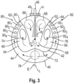
- the Fig.3 a downstream end wall 40 viewed in the main exhaust gas flow direction A and delimiting the mixing zone 36 in the downstream direction, i.e. towards the channel region 34, and arranged offset with respect to the upstream end wall 38 in the downstream direction along the housing longitudinal axis G.
- a reactant delivery arrangement 46 also generally referred to as an injector, is provided, which is supported, for example, by means of a nozzle 48 on the housing wall 20 of the exhaust gas guide housing 18 and is designed to deliver a reactant R, for example in the form of a spray cone, in a reactant main delivery direction H into the mixing zone 36.
- the reactant main delivery direction H can be oriented along a reactant delivery line L, which can be arranged orthogonally with respect to the housing longitudinal axis G and with which, for example, a line parallel to the plane of the drawing of the Fig.1 corresponding plane.
- the reactant main delivery direction H can, for example, correspond to the center line of a spray cone of the reactant R delivered by the reactant delivery arrangement 46.
- the reactant delivery arrangement 46 can be carried on the exhaust gas guide housing 18 in such a way that, for example, the reactant main delivery direction H in the plane of the drawing of the Fig.1 regarding the presented, to the housing longitudinal axis G essentially orthogonal alignment, for example opposite to the main exhaust gas flow direction A or aligned with the main exhaust gas flow direction A.
- An orientation out of the plane of the drawing is also possible in principle.
- the reactant delivery line L can basically be viewed as a line which connects the location at which the reactant R is injected into the mixing zone 36 in the region of the housing wall 20 with the housing longitudinal axis G.
- the two chambers 42, 44 of the mixing zone 36 are separated from one another between the two end walls 38, 40 by two guide walls 50, 52 and a partition wall 54.
- the guide walls 50, 52 and the partition wall 54 extend essentially in the direction of the housing longitudinal axis G between the end walls 38, 40 and can abut against them or be connected to them, for example by welding or soldering.
- the two guide walls 50, 52 extend on both sides of the reactant discharge line L and thus also on both sides of the reactant discharge arrangement 46 relative to one another with respect to a line spanned by the reactant discharge line L and the housing longitudinal axis G and extending to the plane of the drawing of the Fig.3 orthogonal plane E are essentially mirror-symmetrical and, starting from the housing wall 20, run towards one another to form a funnel-like shape of a first chamber region 56 of the first chamber 42 and end in the region of a transition opening 58. In the region of this transition opening 58, the first chamber region 56 merges into a second chamber region 60 of the first chamber 32.
- the second chamber region 60 is also essentially mirror-symmetrical to the plane E and leads in the circumferential direction on both sides of the reactant discharge line L away from the reactant discharge line L along the partition wall 54.
- the partition wall 54 separates the first chamber 42, in particular the second chamber region 60 of the first chamber 42, from the second chamber 40 which surrounds the first chamber 42 radially on the outside in the circumferential direction. This extends, starting from the reactant discharge line L or the Plane E, essentially mirror-symmetrical to this, respectively to chamber end regions 62, 64, where the second chamber 44 is delimited by the partition walls 50, 52 adjoining the housing wall 20 in the circumferential direction and thus also to the first chamber region 56 of the first chamber 42.
- the first chamber 42 is surrounded radially on the outside by the second chamber 44 and is thermally shielded from the outside.
- First inflow openings 66, 68 are arranged in the upstream end wall 38 eccentrically to the housing longitudinal axis G in an area close to the reactant delivery arrangement 46 on both sides of the reactant delivery line L or the plane E also spanned by it.
- the exhaust gas flow which flows essentially in the main exhaust gas flow direction A or also exits the particle filter arrangement 14, enters the first chamber 42, in particular the first chamber area 56 thereof, from the channel area 32 through the first inflow openings 66, 68.
- the two first inflow openings 66, 68 are positioned such that a web 70 of the upstream end wall 38 formed between them covers the flow of the reactant R delivered by the reactant delivery arrangement 46 or shields it from the exhaust gas flow.
- the exhaust gas thus enters the first chamber region 56 on both sides of the reactant flow or the spray cone emitted by the reactant delivery arrangement 46 and mixes there with the reactant R.
- the exhaust gas and the reactant R then flow further through the transition opening 58 into the second channel region 60.
- Opposite the transition opening 58 is a curved region 72 of the partition wall 54 that is concave in the direction of the first chamber region 52. This curved region 72 deflects the flow of exhaust gas and reactant R to both sides with respect to the reactant delivery line L or the plane E into the sections of the second chamber region 60 that extend on both sides of the plane E.
- the downstream end wall 40 has a first outflow opening 74 or 76 on both sides of the reactant discharge line L or the plane E.
- a second inflow opening 78 is also formed eccentrically to the housing longitudinal axis G and, for example, opposite the two first inflow openings 66, 68 with respect to the housing longitudinal axis G. This is located essentially in an area between the housing wall 20 and the curved area 72 of the partition wall 54, so that in this curved area 72 the partition wall 54 partially surrounds the second inflow opening 78. This ensures that the exhaust gas entering the second chamber 44 in the area of the second inflow opening 78 heats the partition wall 54, particularly in the area in which the mixture of exhaust gas and reactant R leaving the first chamber area 56 impinges on the partition wall 54. This supports the evaporation of droplets of reactant R carried in the exhaust gas when they hit the partition wall 54 in the curvature region 72 and thus the improved mixing of exhaust gas and reactant R.
- the second chamber 44 extends, starting from the second inflow opening 78, in both circumferential directions along the housing wall 20 or the partition wall 54 to the chamber end regions 62, 64 and thus assumes the configuration already mentioned, which shields the first chamber 42 in large areas radially outward.
- two groups 80, 82 are formed in the downstream end wall 40, each with a plurality of second outflow openings 80 1 , 80 2 , 80 3 , 80 4 or 82 1 , 82 2 , 82 3 , 82 4 .
- the exhaust gas entering the second chamber 40 through the second inflow opening 78 leaves the second chamber 40 in the direction of the channel region 34 and mixes there with the mixture of exhaust gas and reactant R flowing equally into the channel region 34 through the first outflow openings 74, 76.
- the deflection of the exhaust gas flow in the first chamber 42 when entering through the first inflow openings 66, 68, when flowing through the transition opening 58, when flowing along the second chamber region 60 and when exiting through the first outflow openings 74, 76 and the resulting turbulence forces an efficient mixing of the exhaust gas with the reactant R injected into it.
- This mixing is supported by the fact that the structure of the mixing zone 36 or the two end walls 38, 40 and the guide walls 50, 52 or also the partition wall 54 to the reactant discharge line L or the plane E spanned by this is essentially mirror-symmetrical.
- first inlet opening can be provided on both sides of the reactant discharge line L in association with the first chamber 42, in which case too, an arrangement symmetrical with respect to the reactant discharge line L is preferably selected.
- first outflow openings 74, 76 leading out of the first chamber 42 can be provided.
- second outflow openings in the two groups 80, 82 can deviate from the number shown.
- one or each of these groups could also have only a single second outflow opening.
- the single second inflow opening 78 arranged essentially mirror-symmetrically to the reactant discharge line L
- several second inflow openings arranged mirror-symmetrically to the reactant discharge line L or to the plane E could also be provided.
- the design principles described above can be used in an advantageous manner especially when the mixing zone 36 or the exhaust gas guide housing 18 has the circular outer peripheral contour shown in the figures.
- the mixing zone 36 or the exhaust gas guide housing 18 could also have a different cross-sectional geometry, for example a flattened round one, such as an elliptical cross-sectional geometry, in which case an essentially symmetrical design can be provided with respect to a reactant discharge line corresponding, for example, to the short semi-axis of an elliptical contour.
- Deviations from an exact symmetrical structure are also possible, for example in that the openings arranged on both sides of the reactant input line L but corresponding to one another have different shapes and/or sizes or different distances from the reactant discharge line L or from the plane E.
- the various walls forming the mixing zone 36 i.e. the two end walls 38, 40 and the guide walls 50, 52 as well as the partition wall 54, can be firmly connected to one another where they abut one another, for example by soldering or welding, at certain points or along the entire contact area.
- the guide walls 50, 52 can be connected to the housing wall 20 where they adjoin it, at certain points or along the entire contact area, by soldering or welding, so that the two chambers 42, 44 are essentially separated from one another in terms of flow.
- a completely gas-tight separation of these two chambers 42, 44 is not absolutely necessary, although this can be advantageous to prevent reactant R from entering the second chamber 44.
Landscapes
- Chemical & Material Sciences (AREA)
- Engineering & Computer Science (AREA)
- Chemical Kinetics & Catalysis (AREA)
- Combustion & Propulsion (AREA)
- Health & Medical Sciences (AREA)
- Mechanical Engineering (AREA)
- Toxicology (AREA)
- General Engineering & Computer Science (AREA)
- Biomedical Technology (AREA)
- Environmental & Geological Engineering (AREA)
- Analytical Chemistry (AREA)
- General Chemical & Material Sciences (AREA)
- Oil, Petroleum & Natural Gas (AREA)
- Dispersion Chemistry (AREA)
- Exhaust Gas After Treatment (AREA)
Description
- Die vorliegende Erfindung betrifft eine Abgas/Reaktionsmittel-Mischanordnung für eine Abgasanlage einer Brennkraftmaschine, beispielsweise in einem Fahrzeug, mit welcher das von der Brennkraftmaschine ausgestoßene Abgas effizient mit in das Abgas eingespritztem Reaktionsmittel, beispielsweise einer Harnstoff/WasserLösung, durchmischt werden kann.
- Zur Verringerung des Stickoxidanteils in von einer Diesel-Brennkraftmaschine ausgestoßenem Abgas ist es bekannt, in einer SCR-Katalysatoranordnung eine selektive katalytische Reduktion durchzuführen. Dazu wird stromaufwärts der SCR-Katalysatoranordnung ein Reaktionsmittel, beispielsweise eine Harnstoff/WasserLösung, in das Abgas eingespritzt. Vor dem Einleiten in die SCR-Katalysatoranordnung muss eine effiziente Durchmischung von Abgas und Reaktionsmittel erfolgen. Dabei besteht das Problem, dass beispielsweise bedingt durch eine Kondensation des im Allgemeinen in flüssiger Form eingespritzten Reaktionsmittels an einer Innenoberfläche eines den Abgasstrom führenden Gehäuses flüssiges Reaktionsmittel sich ansammeln und Ablagerungen bilden kann. Eine nicht ausreichende Durchmischung von Abgas und Reaktionsmittel kann weiter dazu führen, dass ein Teil des flüssigen Reaktionsmittels in die SCR-Katalysatoranordnung gelangt und somit für eine effiziente Durchführung einer katalytischen Reaktion im Wesentlichen nicht zur Verfügung steht. Die Gefahr einer nicht ausreichenden Durchmischung von Reaktionsmittel und Abgas ist vor allem dann gegeben, wenn für einen kompakten Aufbau einer Abgasanlage der Abstand zwischen dem Ort, an welchem das Reaktionsmittel beispielsweise im Wesentlichen orthogonal zum Abgasstrom eingespritzt wird, und der SCR-Katalysatoranordnung in Strömungsrichtung vergleichsweise gering ist.
- Eine Abgas/Reaktionsmittel-Mischanordnung gemäß dem Oberbegriff des Anspruchs 1 ist aus der
EP 3 757 364 A1 bekannt. - Es ist die Aufgabe der vorliegenden Erfindung, eine Abgas/Reaktionsmittel-Mischanordnung vorzusehen, welche bei kompaktem Aufbau eine effiziente Durchmischung von Abgas und Reaktionsmittel gewährleistet.
- Erfindungsgemäß wird diese Aufgabe gelöst durch eine Abgas/Reaktionsmittel-Mischanordnung für eine Abgasanlage einer Brennkraftmaschine zur Durchmischung von Abgas und Reaktionsmittel gemäß Anspruch 1. Diese Abgas/Reaktionsmittel-Mischanordnung umfasst:
- ein in Richtung einer Gehäuselängsachse sich erstreckendes Abgasführungsgehäuse mit einer Gehäusewand, wobei in dem Abgasführungsgehäuse ein von der Gehäusewand umgebener und von Abgas durchströmbarer Abgaskanal gebildet ist,
- ein zwischen einer stromaufwärtigen Stirnwand und einer stromabwärts bezüglich der stromaufwärtigen Stirnwand angeordneten stromabwärtigen Stirnwand gebildete Mischzone, wobei die Mischzone eine erste Kammer und eine zweite Kammer umfasst,
- eine an dem Abgasführungsgehäuse getragene Reaktionsmittelabgabeanordnung zur Abgabe von Reaktionsmittel in die erste Kammer in einer im Wesentlichen entlang einer Reaktionsmittelabgabelinie orientierten Reaktionsmittel-Hauptabgaberichtung,
- wobei in der stromaufwärtigen Stirnwand wenigstens eine erste Einströmöffnung vorgesehen ist, wobei über die wenigstens eine erste Einströmöffnung ein stromaufwärts bezüglich der stromaufwärtigen Stirnwand liegender Bereich des Abgaskanals zu der ersten Kammer offen ist,
- wobei in der stromaufwärtigen Stirnwand wenigstens eine zweite Einströmöffnung vorgesehen ist, wobei über die wenigstens eine zweite Einströmöffnung der stromaufwärts bezüglich der stromaufwärtigen Stirnwand liegende Bereich des Abgaskanals zu der zweiten Kammer offen ist,
- wobei in der stromabwärtigen Stirnwand wenigstens eine erste Ausströmöffnung vorgesehen ist, wobei über die wenigstens eine erste Ausströmöffnung die erste Kammer zu einem stromabwärts bezüglich der stromabwärtigen Stirnwand liegenden Bereich des Abgaskanals offen ist,
- wobei in der stromabwärtigen Stirnwand wenigstens eine zweite Ausströmöffnung vorgesehen ist, wobei über die wenigstens eine zweite Ausströmöffnung die zweite Kammer zu dem stromabwärts bezüglich der stromabwärtigen Stirnwand liegenden Bereich des Abgaskanals offen ist.
- Durch die Aufteilung der zwischen den beiden Stirnwänden begrenzten Mischzone in zwei Kammern und das Einspritzen von Reaktionsmittel in eine dieser beiden Kammern werden einerseits die Durchmischung unterstützende Strömungsbedingungen geschaffen. Andererseits kann durch die geometrische Anordnung der beiden Kammern bezüglich einander dafür gesorgt werden, dass diejenige Kammer, in welche das Reaktionsmittel eingespritzt wird, also die erste Kammer, durch die zweite Kammer nach außen bzw. bezüglich der Gehäusewand in weiten Bereichen abgeschirmt ist. Die Gefahr einer Kondensation von Reaktionsmittel an einer die erste Kammer umgrenzenden Wand kann dadurch gemindert werden.
- Um die beiden Kammern der Mischzone funktional voneinander zu trennen, besteht zwischen der ersten Kammer und der zweiten Kammer im Wesentlichen keine Strömungsverbindung. Es ist darauf hinzuweisen, dass die beiden Kammern nicht notwendigerweise vollständig gasdicht voneinander getrennt werden müssen. Gasleckagen beispielsweise dort, wo die Kammern voneinander trennende bzw. begrenzenden Wände aneinander anschließen, beeinträchtigen die Funktionalität der erfindungsgemäßen Abgas/Reaktionsmittel-Mischanordnung nicht.
- Wenn in der stromaufwärtigen Stirnwand wenigstens zwei erste Einströmöffnungen vorgesehen sind, wobei in Umfangsrichtung beidseits der Reaktionsmittelabgabelinie jeweils wenigstens eine erste Einströmöffnung vorgesehen ist, ist dafür gesorgt, dass ein zwischen den ersten Einströmöffnungen gebildeter Steg in der ersten Stirnwand den in die erste Kammer eingespritzten Reaktionsmittelstrom gegen die direkte Anströmung mit Abgas abschirmt, so dass der Reaktionsmittelstrom definiert in die erste Kammer eingeleitet werden kann.
- Für eine über den Querschnitt der Abgas/Reaktionsmittel-Mischanordnung gleichmäßige Durchmischung von Abgas und Reaktionsmittel wird vorgeschlagen, dass die in Umfangsrichtung beidseits der Reaktionsmittelabgabelinie vorgesehenen ersten Einströmöffnungen zu einer die Reaktionsmittelabgabelinie und die Gehäuselängsachse enthaltenden Ebene im Wesentlichen spiegelsymmetrisch angeordnet sind.
- Für die gleichmäßige Abgabe des Gemisches aus Abgas und Reaktionsmittel in den Abgaskanal können in der stromabwärtigen Stirnwand wenigstens zwei erste Ausströmöffnungen vorgesehen sein, wobei in Umfangsrichtung beidseits der Reaktionsmittelabgabelinie jeweils wenigstens eine erste Ausströmöffnung vorgesehen ist.
- Auch hierbei ist es vorteilhaft, wenn die in Umfangsrichtung beidseits der Reaktionsmittelabgabelinie vorgesehenen ersten Ausströmöffnungen zu der die Reaktionsmittelabgabelinie und die Gehäuselängsachse enthaltenden Ebene im Wesentlichen spiegelsymmetrisch angeordnet sind.
- Um einen direkten Hindurchtritt von Abgas durch die Mischzone in Richtung der Gehäuselängsachse zu verhindern, kann vorgesehen sein, dass in Umfangsrichtung an wenigstens einer, vorzugsweise jeder Seite der Reaktionsmittelabgabelinie die ersten Einströmöffnungen näher an der Reaktionsmittelabgabelinie angeordnet sind, als die ersten Ausströmöffnungen, oder/und dass in Umfangsrichtung an wenigstens einer, vorzugsweise jede Seite der Reaktionsmittelabgabelinie zwischen den ersten Einströmöffnungen und den ersten Ausströmöffnungen jeweils eine zwischen der stromaufwärtigen Stirnwand und der stromabwärtigen Stirnwand sich erstreckende, vorzugsweise an die Gehäusewand anschließende Leitwand angeordnet ist.
- Für eine effiziente Vermischung von Abgas und Reaktionsmittel in der ersten Kammer kann zwischen den in Umfangsrichtung beidseits der Reaktionsmittelabgabelinie angeordneten Leitwänden ein in der Reaktionsmittel-Hauptabgaberichtung sich verjüngender erster Kammerbereich der ersten Kammer gebildet sein, wobei der erste Kammerbereich an einer Übergangsöffnung zu einem zweiten Kammerbereich der ersten Kammer offen ist, wobei der zweite Kammerbereich ausgehend von der Übergangsöffnung zwischen dem ersten Kammerbereich und dem zweiten Kammerbereich beidseits der Reaktionsmittelabgabelinie zu den ersten Ausströmöffnungen führt.
- Wenn der erste Kammerbereich oder/und der zweite Kammerbereich zu der die Reaktionsmittelabgabelinie und die Gehäuselängsachse enthaltenden Ebene im Wesentlichen spiegelsymmetrisch angeordnet ist, wird eine über den Querschnitt der Mischzone gleichmäßige Mischcharakteristik unterstützt.
- Um die beiden Kammern der Mischzone voneinander zu trennen, kann eine die erste Kammer von der zweiten Kammer trennende, zwischen der stromaufwärtigen Stirnwand und der stromabwärtigen Stirnwand sich erstreckende Trennwand vorgesehen sein. Um dabei die erste Kammer durch die zweite Kammer nach außen thermisch abzuschirmen, ist es besonders vorteilhaft, wenn die Trennwand die erste Kammer nach radial außen zur zweiten Kammer begrenzt.
- Beispielsweise kann die Trennwand sich zwischen den Leitwänden im Wesentlichen in Umfangsrichtung entlang der Gehäusewand erstrecken, so dass auch die beiden Leitwände die Trennung der beiden Kammern der Mischzone voneinander unterstützen bzw. die zweite Kammer in Umfangsrichtung begrenzen. Dabei kann auch die Trennwand zu der die Reaktionsmittelabgabelinie und die Gehäuselängsachse enthaltenden Ebene im Wesentlichen spiegelsymmetrisch angeordnet sein.
- Zur Abgabe von Abgas aus der zweiten Kammer kann in der stromabwärtigen Stirnwand in jedem an eine der Leitwände angrenzenden Kammerendbereich der zweiten Kammer jeweils eine Gruppe vorzugsweise mit einer Mehrzahl von im Wesentlichen in Umfangsrichtung aufeinanderfolgenden zweiten Ausströmöffnungen vorgesehen sein.
- Auch hier wird eine über den Querschnitt gleichmäßige Mischcharakteristik unterstützt, wenn die in den beiden Kammerendbereichen der zweiten Kammer vorgesehenen Gruppen von zweiten Ausströmöffnungen zu der die Reaktionsmittelabgabelinie und die Gehäuselängsachse enthaltenden Ebene im Wesentlichen spiegelsymmetrisch angeordnet sind.
- Zur Unterstützung der Verdampfung von Reaktionsmittel in der ersten Kammer kann die zweite Einströmöffnung zwischen der Trennwand und der Gehäusewand angeordnet sein, und die Trennwand kann im Bereich der zweiten Einströmöffnung zur ersten Kammer hin konkav geformt sein.
- Auch hierbei ist es vorteilhaft, wenn die zweite Einströmöffnung zu der die Reaktionsmittelabgabelinie und die Gehäuselängsachse enthaltenden Ebene im Wesentlichen spiegelsymmetrisch angeordnet ist, oder/und wenn die stromaufwärtige Stirnwand oder/und die stromabwärtige Stirnwand zu der die Reaktionsmittelabgabelinie und die Gehäuselängsachse enthaltenden Ebene im Wesentlichen spiegelsymmetrisch ausgebildet ist.
- Die Reaktionsmittelabgabelinie kann zu der Gehäuselängsachse im Wesentlichen orthogonal verlaufen, wobei beispielsweise bei rohrartiger Ausgestaltung des Abgasführungsgehäuses die Gehäuselängsachse eine geradlinig sich erstreckenden Linie sein kann.
- Die Erfindung betrifft ferner eine Abgasanlage für eine Brennkraftmaschine, umfassend eine erfindungsgemäß aufgebaute Abgas/Reaktionsmittel-Mischanordnung und stromabwärts der Abgas/Reaktionsmittel-Mischanordnung eine SCR-Katalysatoranordnung.
- Die vorliegende Erfindung wird nachfolgend mit Bezug auf die beiliegenden Figuren detailliert beschrieben es zeigt:
- Fig. 1
- eine prinzipielle Längsschnittansicht einer Abgasanlage mit einer Abgas/Reaktionsm ittel-M ischanordnung;
- Fig. 2
- eine Querschnittansicht der Abgasanlage der
Fig. 1 , geschnitten längs einer Linie II-II inFig. 1 ; - Fig. 3
- eine Querschnittansicht der Abgasanlage der
Fig. 1 , geschnitten längs einer Linie III-III inFig. 1 . - In
Fig. 1 ist ein Abschnitt einer allgemein mit 10 bezeichneten Abgasanlage einer Brennkraftmaschine beispielsweise in einem Fahrzeug dargestellt. Diese Abgasanlage 10 umfasst als zentralen Bestandteil eine Abgas/Reaktionsmittel-Mischanordnung 12, die in der Abgasanlage 10 beispielsweise stromabwärts einer Partikelfilteranordnung 14 und stromaufwärts einer SCR-Katalysatoranordnung 16 angeordnet sein kann. - Die Abgas/Reaktionsmittel-Mischanordnung 12 umfasst ein beispielsweise rohrartiges, in Richtung einer Gehäuselängsachse G langgestrecktes Abgasführungsgehäuse 18 mit einer im Wesentlichen zylindrisch und beispielsweise mit kreisrundem Querschnitt ausgebildeten Gehäusewand 20. In diesem Abgasführungsgehäuse 18 kann stromaufwärts bezüglich der Abgas/Reaktionsmittel-Mischanordnung 12 die Partikelfilteranordnung 14 getragen sein. Beispielsweise kann die Partikelfilteranordnung 14 einen monolithisch aufgebauten Partikelfilterblock 22 umfassen, der von einer Fasermatte 24 oder dergleichen umwickelt in dem Abgasführungsgehäuse 18 getragen ist. Auch die stromabwärts der Abgas/Reaktionsmittel-Mischanordnung 12 angeordnete SCR-Katalysatoranordnung 16 kann in dem Abgasführungsgehäuse 18 getragen sein und kann einen beispielsweise monolithisch aufgebauten Katalysatorblock 26 umfassen, der durch eine diese umgebende Fasermatte 28 oder dergleichen in dem Abgasführungsgehäuse 18 getragen sein kann.
- Es ist darauf hinzuweisen, dass die Abgasanlage 10 bzw. das Abgasführungsgehäuse 18 in mehrere in einer Abgas-Hauptströmungsrichtung A aufeinander folgende und beispielsweise miteinander verbunden Segmente unterteilt sein kann, von welchen beispielsweise eines der Segmente die Partikelfilteranordnung 14 enthalten kann, eines der Segmente die nachfolgend detailliert beschriebene Abgas/Reaktionsmittel-Mischanordnung 12 enthalten bzw. bereitstelen kann, und eines der Segmente die SCR-Katalysatoranordnung 16 enthalten kann.
- In dem Abgasführungsgehäuse 18 ist ein von Abgas im Wesentlichen in der Abgas-Hauptströmungsrichtung durchströmbarer Abgaskanal 30 gebildet, wobei der Kanal 30 einen stromaufwärts bezüglich der Abgas/Reaktionsmittel-Mischanordnung 12 liegenden Kanalbereich 32 und einen stromabwärts bezüglich der Abgas/Reaktionsmittel-Mischanordnung 12 liegenden Kanalbereich 34 aufweist.
- Die
Fig. 2 zeigt eine eine Mischzone 36 in Richtung stromaufwärts, also zum Kanalbereich 32 begrenzende stromaufwärtige Stirnwand 38 betrachtet in der Abgas-Hauptströmungsrichtung A. Gleichermaßen zeigt dieFig. 3 eine in der Abgas-Hauptströmungsrichtung A betrachtete und die Mischzone 36 in Richtung stromabwärts, also zum Kanalbereich 34 begrenzenden und bezüglich der stromaufwärtigen Stirnwand 38 in Richtung stromabwärts entlang der Gehäuselängsachse G versetzt angeordnete stromabwärtige Stirnwand 40. - In Richtung der Gehäuselängsachse G sind zwischen den beiden Stirnwänden 38, 40 zwei Kammern 42, 44 der Mischzone 36 gebildet. Ferner ist in Zuordnung zu der Mischzone 36 eine allgemein auch als Injektor bezeichnete Reaktionsmittelabgabeanordnung 46 vorgesehen, die beispielsweise vermittels eines Stutzens 48 an der Gehäusewand 20 des Abgasführungsgehäuses 18 getragen ist und dazu ausgebildet ist, ein Reaktionsmittel R beispielsweise in Form eines Sprühkegels in einer Reaktionsmittel-Hauptabgaberichtung H in die Mischzone 36 abzugeben. Dabei kann die Reaktionsmittel-Hauptabgaberichtung H entlang einer Reaktionsmittelabgabelinie L orientiert sein, welche bezüglich der Gehäuselängsachse G orthogonal angeordnet sein kann und mit dieser beispielsweise eine der Zeichenebene der
Fig. 1 entsprechende Ebene aufspannen kann. Die Reaktionsmittel-Hauptabgaberichtung H kann beispielsweise der Mittenlinie eines von der Reaktionsmittelabgabeanordnung 46 abgegebenen Sprühkegels des Reaktionsmittels R entsprechen. - Es sei darauf hingewiesen, dass nicht notwendigerweise die verschiedenen vorangehend angesprochenen Richtungen bzw. Linien exakt orthogonal zueinander angeordnet sein müssen bzw. einander entsprechen müssen. So kann beispielsweise die Reaktionsmittelabgabeanordnung 46 so am Abgasführungsgehäuse 18 getragen sein, dass beispielsweise die Reaktionsmittel-Hauptabgaberichtung H in der Zeichenebene der
Fig. 1 bezüglich der dargestellten, zur Geäuselängsachse G im Wesentlichen orthogonalen Ausrichtung beispielsweise entgegen der Abgas-Hauptströmungsrichtung A oder mit der Abgas-Hauptströmungsrichtung A angestellt orientiert ist. Auch eine Orientierung aus der Zeichenebene heraus ist grundsätzlich möglich. Die Reaktionsmittelabgabelinie L kann dabei grundsätzlich als eine Linie betrachtet werden, welche den Ort, an welchem im Bereich der Gehäusewandung 20 das Reaktionsmittel R in die Mischzone 36 eingespritzt wird, mit der Gehäuselängsachse G verbindet. - Die beiden Kammern 42, 44 der Mischzone 36 sind zwischen den beiden Stirnwänden 38, 40 durch zwei Leitwände 50, 52 und eine Trennwand 54 voneinander getrennt. Die Leitwände 50, 52 und die Trennwand 54 erstrecken sich im Wesentlichen in Richtung der Gehäuselängsachse G zwischen den Stirnwänden 38, 40 und können an diese stumpf anstoßen bzw. mit diesen beispielsweise durch Verschweißen oder Verlöten verbunden sein.
- Die beiden Leitwände 50, 52 erstrecken sich beidseits der Reaktionsmittelabgabelinie L und somit auch beidseits der Reaktionsmittelabgabeanordnung 46 zueinander bezüglich einer durch die Reaktionsmittelabgabelinie L und die Gehäuselängsachse G aufgespannten und zur Zeichenebene der
Fig. 3 orthogonalen Ebene E im Wesentlichen spiegelsymmetrisch und verlaufen, ausgehend von der Gehäusewand 20, zum Bilden einer trichterartigen Gestalt eines ersten Kammerbereichs 56 der ersten Kammer 42 aufeinander zu und enden im Bereich einer Übergangsöffnung 58. Im Bereich dieser Übergangsöffnung 58 geht der erste Kammerbereich 56 in einen zweiten Kammerbereich 60 der ersten Kammer 32 über. Ebenso wie der erste Kammerbereich 56 ist auch der zweite Kammerbereich 60 zur Ebene E im Wesentlichen spiegelsymmetrisch ausgestaltet und führt in Umfangsrichtung beidseits der Reaktionsmittelabgabelinie L von der Reaktionsmittelabgabelinie L entlang der Trennwand 54 weg. - Die Trennwand 54 trennt die erste Kammer 42, insbesondere den zweiten Kammerbereich 60 der ersten Kammer 42, von der in weiten Bereichen in Umfangsrichtung die erste Kammer 42 radial außen umgebenden zweiten Kammer 40. Diese erstreckt sich, ausgehend von der Reaktionsmittelabgabelinie L bzw. der Ebene E, im Wesentlichen spiegelsymmetrisch zu dieser jeweils zu Kammerendbereichen 62, 64, wo die zweite Kammer 44 durch die an die Gehäusewand 20 anschließenden Trennwände 50, 52 in Umfangsrichtung und somit auch zum ersten Kammerbereich 56 der ersten Kammer 42 begrenzt ist. Somit ist in weiten Bereichen die erste Kammer 42 radial außen von der zweiten Kammer 44 umgeben und nach außen hin thermisch abgeschirmt.
- In der stromaufwärtigen Stirnwand 38 sind exzentrisch zur Gehäuselängsachse G in einem der Reaktionsmittelabgabeanordnung 46 nahe liegenden Bereich beidseits der Reaktionsmittelabgabelinie L bzw. der durch diese auch aufgespannten Ebene E erste Einströmöffnungen 66, 68 angeordnet. Durch die ersten Einströmöffnungen 66, 68 hindurch tritt der im Wesentlichen in der Abgas-Hauptströmungsrichtung A heranströmende bzw. auch aus der Partikelfilteranordnung 14 austretende Abgasstrom aus dem Kanalbereich 32 in die erste Kammer 42, insbesondere den ersten Kammerbereich 56 derselben ein. Die beiden ersten Einströmöffnungen 66, 68 sind so positioniert, dass ein zwischen diesen gebildeter Steg 70 der stromaufwärtigen Stirnwand 38 den von der Reaktionsmittelabgabeanordnung 46 abgegebenen Strom des Reaktionsmittels R überdeckt bzw. gegen den Abgasstrom abschirmt. Das Abgas tritt somit beidseits des Reaktionsmittelstroms bzw. des von der Reaktionsmittelabgabeanordnung 46 abgegebenen Sprühkegels in den ersten Kammerbereich 56 ein und vermischt sich bereits dort mit dem Reaktionsmittel R. Das Abgas und das Reaktionsmittel R strömen dann weiter durch die Übergangsöffnung 58 in den zweiten Kanalbereich 60. Der Übergangsöffnung 58 liegt ein in Richtung zum ersten Kammerbereich 52 konkav geformter Wölbungsbereich 72 der Trennwand 54 gegenüber. Durch diesen Wölbungsbereich 72 wird der Strom aus Abgas und Reaktionsmittel R zu beiden Seiten bezüglich der Reaktionsmittelabgabelinie L bzw. der Ebene E abgelenkt in die beidseits der Ebene E sich erstreckenden Abschnitte des zweiten Kammerbereichs 60.
- In dem diese Abschnitte überdeckenden Bereichen weist die stromabwärtige Stirnwand 40 beidseits der Reaktionsmittelabgabelinie L bzw. der Ebene E jeweils eine erste Ausströmöffnung 74 bzw. 76 auf. Durch diese ersten Ausströmöffnungen 74, 76 strömt das in der ersten Kammer 42 gebildete Gemisch aus Abgas und Reaktionsmittel R aus der Mischzone 36 in den Kanalbereich 34 des Abgaskanals 30 stromabwärts der Mischzone 36 bzw. stromaufwärts der SCR-Katalysatoranordnung 16.
- In der stromaufwärtigen Stirnwand 38 ist ferner exzentrisch zur Gehäuselängsachse G und beispielsweise bezüglich der Gehäuselängsachse G den beiden ersten Einströmöffnungen 66, 68 gegenüberliegend eine zweite Einströmöffnung 78 gebildet. Diese liegt im Wesentlichen in einem Bereich zwischen der Gehäusewand 20 und dem Wölbungsbereich 72 der Trennwand 54, so dass in diesem Wölbungsbereich 72 die Trennwand 54 die zweite Einströmöffnung 78 bereichsweise umgebend verläuft. Dadurch wird gewährleistet, dass durch in die zweite Kammer 44 im Bereich der zweiten Einströmöffnung 78 eintretendes Abgas die Trennwand 54 insbesondere in demjenigen Bereich, in welchem das den ersten Kammerbereich 56 verlassende Gemisch aus Abgas und Reaktionsmittel R auf die Trennwand 54 auftrifft, erwärmt wird. Dadurch wird die Verdampfung von im Abgas mitgeführten Tröpfchen von Reaktionsmittel R beim Auftreffen auf die Trennwand 54 im Wölbungsbereich 72 und somit die verbesserte Durchmischung von Abgas und Reaktionsmittel R unterstützt.
- Die zweite Kammer 44 erstreckt sich, ausgehend von der zweiten Einströmöffnung 78, in beiden Umfangsrichtungen entlang der Gehäusewand 20 bzw. der Trennwand 54 zu den Kammerendbereichen 62, 64 und nimmt somit die bereits angesprochene, die erste Kammer 42 in weiten Bereichen nach radial außen abschirmende Konfiguration an. Im Bereich der Kammerendbereiche 62, 64 sind in der stromabwärtigen Stirnwand 40 zwei Gruppen 80, 82 jeweils mit einer Mehrzahl zweiter Ausströmöffnungen 801, 802, 803, 804 bzw. 821, 822, 823, 824 ausgebildet. Durch diese näherungsweise in Umfangsrichtung aufeinander folgenden zweiten Ausströmöffnungen 801, 802, 803, 804 bzw. 821, 822, 823, 824 verlässt das durch die zweite Einströmöffnung 78 in die zweite Kammer 40 eintretende Abgas die zweite Kammer 40 in Richtung zum Kanalbereich 34 und vermischt sich dort mit dem durch die ersten Ausströmöffnungen 74, 76 gleichermaßen in den Kanalbereich 34 strömenden Gemisch aus Abgas und Reaktionsmittel R.
- Mit dem vorangehend beschriebenen Aufbau der Mischzone 36 in der Abgas/Reaktionsmittel-Mischanordnung 12 wird bei axial, also in Richtung der Gehäuselängsachse G bzw. der Abgas-Hauptströmungsrichtung A kompakter Bauweise eine effiziente Durchmischung von Abgas und Reaktionsmittel R erreicht, wobei durch die Anordnung der beiden Kammern 42, 44 der Mischzone 36 zueinander derjenige Bereich, in welchen das Reaktionsmittel R eingespritzt wird, durch den die zweite Kammer 44 durchströmenden Teil des im Abgaskanal 30 strömenden Abgases effizient nach außen abgeschirmt wird. Somit ist die Gefahr, dass an der Trennwand 54 bzw. auch den Leitwänden 50, 52 vor allem bei vergleichsweise niedriger Umgebungstemperatur Reaktionsmittel R kondensiert und Ablagerungen bildet, deutlich gemindert. Gleichzeitig wird durch die Umlenkung des Abgasstroms in der ersten Kammer 42 beim Eintreten durch die ersten Einströmöffnungen 66, 68 in diese, beim Durchströmen der Übergangsöffnung 58, beim Strömen entlang des zweiten Kammerbereichs 60 und beim Austritt durch die ersten Ausströmöffnungen 74, 76 und die dabei entstehenden Verwirbelungen eine effiziente Durchmischung des Abgases mit dem in dieses eingespritzten Reaktionsmittel R erzwungen. Diese Durchmischung wird dadurch unterstützt, dass der Aufbau der Mischzone 36 bzw. der beiden Stirnwände 38, 40 und der Leitwände 50, 52 bzw. auch der Trennwand 54 zur Reaktionsmittelabgabelinie L bzw. der von dieser auch aufgespannten Ebene E im Wesentlichen spiegelsymmetrisch ausgebildet ist. Dadurch wird vor allem bei niedrigen Umgebungstemperaturen eine verbesserte Abgasreinigung in der SCR-Katalysatoranordnung 16 im Kaltstart und bei niedrigen Lastpunkten erreicht, in welchen insbesondere am Beginn eines Verbrennungsbetriebs einer Brennkraftmaschine auch der von dieser ausgestoßene Abgasstrom noch eine vergleichsweise niedrige Temperatur aufweist.
- Es sei abschließend darauf hingewiesen, dass die Prinzipien der vorliegenden Erfindung selbstverständlich auch Anwendung finden können, wenn von den vorangehend mit Bezug auf die
Fig. 1 bis 3 dargestellten Prinzipien in verschiedenen Bereichen abgewichen wird. So kann beispielsweise in Zuordnung zur ersten Kammer 42 beidseits der Reaktionsmittelabgabelinie L jeweils mehr als eine erste Eingabeöffnung vorgesehen sein, wobei auch in diesem Falle vorzugsweise eine bezüglich der Reaktionsmittelabgabelinie L symmetrische Anordnung gewählt wird. Entsprechendes gilt auch für die aus der ersten Kammer 42 heraus führenden ersten Ausströmöffnungen 74, 76. Gleichermaßen kann die Anzahl der zweiten Ausströmöffnungen in den beiden Gruppen 80, 82 von der dargestellten Anzahl abweichen. Beispielsweise könnte eine oder jede dieser Gruppen auch nur eine einzige zweite Ausströmöffnung aufweisen. Anstelle der einzigen zur Reaktionsmittelabgabelinie L im Wesentlichen spiegelsymmetrisch angeordneten zweiten Einströmöffnung 78 könnten auch mehrere beispielsweise zur Reaktionsmittelabgabelinie L bzw. zur Ebene E spiegelsymmetrisch angeordnete zweite Einströmöffnungen vorgesehen sein. - Weiter ist darauf hinzuweisen, dass die vorangehend beschriebenen Ausgestaltungsprinzipien vor allem dann in vorteilhafter Weise Anwendung finden können, wenn die Mischzone 36 bzw. das Abgasführungsgehäuse 18 die in den Figuren dargestellte kreisrunde Außenumfangskontur aufweist. Grundsätzlich könnte die Mischzone 36 bzw. das Abgasführungsgehäuse 18 jedoch auch eine andere, beispielsweise eine abgeflacht runde Querschnittsgeometrie, wie z. B. eine elliptische Querschnittsgeometrie, aufweisen, wobei dann gleichermaßen eine im Wesentlichen symmetrische Ausgestaltung zu einer beispielsweise der kurzen Halbachse einer elliptischen Kontur entsprechenden Reaktionsmittelabgabelinie vorgesehen sein kann. Auch Abweichungen von einer exakten symmetrischen Struktur sind möglich, beispielsweise dadurch, dass die beidseits der Reaktionsmitteleingabelinie L angeordneten, einander aber entsprechenden Öffnungen zueinander unterschiedliche Formen oder/und Größen bzw. unterschiedliche Abstände zur Reaktionsmittelabgabelinie L bzw. zur Ebene E aufweisen.
- Die verschiedenen die Mischzone 36 bildenden Wände, also die beiden Stirnwände 38, 40 und die Leitwände 50, 52 sowie auch die Trennwand 54, können dort, wo diese aneinander anstoßen, beispielsweise durch Verlötung oder Verschweißung punktuell oder entlang des gesamten Kontaktbereichs miteinander fest verbunden sein. Gleichermaßen können die Leitwände 50, 52 dort, wo sie an die Gehäusewand 20 anschließen, mit dieser punktuell oder entlang des gesamten Kontaktbereichs durch Verlötung oder Verschweißung verbunden sein, so dass die beiden Kammern 42, 44 strömungstechnisch im Wesentlichen voneinander getrennt sind. Eine vollständig gasdichte Trennung dieser beiden Kammern 42, 44 ist jedoch nicht zwingend erforderlich, wenngleich dies zum Vermeiden, dass Reaktionsmittel R in die zweite Kammer 44 gelangt, vorteilhaft sein kann.
Claims (15)
- Abgas/Reaktionsmittel-Mischanordnung für eine Abgasanlage einer Brennkraftmaschine zur Durchmischung von Abgas und Reaktionsmittel umfassend:- ein in Richtung einer Gehäuselängsachse (G) sich erstreckendes Abgasführungsgehäuse (18) mit einer Gehäusewand (20), wobei in dem Abgasführungsgehäuse (18) ein von der Gehäusewand (20) umgebener und von Abgas durchströmbarer Abgaskanal (30) gebildet ist,- ein zwischen einer stromaufwärtigen Stirnwand (38) und einer stromabwärts bezüglich der stromaufwärtigen Stirnwand (38) angeordneten stromabwärtigen Stirnwand (40) gebildete Mischzone (36), wobei die Mischzone (36) eine erste Kammer (42) und eine zweite Kammer (44) umfasst,- eine an dem Abgasführungsgehäuse (18) getragene Reaktionsmittelabgabeanordnung (46) zur Abgabe von Reaktionsmittel (R) in die erste Kammer (42) in einer im Wesentlichen entlang einer Reaktionsmittelabgabelinie (L) orientierten Reaktionsmittel-Hauptabgaberichtung (H),wobei in der stromaufwärtigen Stirnwand (38) wenigstens eine erste Einströmöffnung (66, 68) vorgesehen ist, wobei über die wenigstens eine erste Einströmöffnung (66, 68) ein stromaufwärts bezüglich der stromaufwärtigen Stirnwand (38) liegender Bereich (32) des Abgaskanals (30) zu der ersten Kammer (42) offen ist,wobei in der stromaufwärtigen Stirnwand (38) wenigstens eine zweite Einströmöffnung (78) vorgesehen ist, wobei über die wenigstens eine zweite Einströmöffnung (78) der stromaufwärts bezüglich der stromaufwärtigen Stirnwand (38) liegende Bereich (32) des Abgaskanals (30) zu der zweiten Kammer (44) offen ist,wobei in der stromabwärtigen Stirnwand (40) wenigstens eine erste Ausströmöffnung (74, 76) vorgesehen ist, wobei über die wenigstens eine erste Ausströmöffnung (74, 76) die erste Kammer (42) zu einem stromabwärts bezüglich der stromabwärtigen Stirnwand (40) liegenden Bereich (34) des Abgaskanals (30) offen ist,wobei in der stromabwärtigen Stirnwand (40) wenigstens eine zweite Ausströmöffnung (801, 802, 803, 804, 821, 822, 823, 824) vorgesehen ist, wobei über die wenigstens eine zweite Ausströmöffnung (801, 802, 803, 804, 821, 822, 823, 824) die zweite Kammer (44) zu dem stromabwärts bezüglich der stromabwärtigen Stirnwand (40) liegenden Bereich (34) des Abgaskanals (30) offen ist,dadurch gekennzeichnet, dass zwischen der ersten Kammer (42) und der zweiten Kammer (44) im Wesentlichen keine Strömungsverbindung besteht.
- Abgas/Reaktionsmittel-Mischanordnung nach Anspruch 1, dadurch gekennzeichnet, dass in der stromaufwärtigen Stirnwand (38) wenigstens zwei erste Einströmöffnungen (66, 68) vorgesehen sind, wobei in Umfangsrichtung beidseits der Reaktionsmittelabgabelinie (L) jeweils wenigstens eine erste Einströmöffnung (66, 68) vorgesehen ist.
- Abgas/Reaktionsmittel-Mischanordnung nach Anspruch 2, dadurch gekennzeichnet, dass die in Umfangsrichtung beidseits der Reaktionsmittelabgabelinie (L) vorgesehenen ersten Einströmöffnungen (66, 68) zu einer die Reaktionsmittelabgabelinie (L) und die Gehäuselängsachse (G) enthaltenden Ebene (E) im Wesentlichen spiegelsymmetrisch angeordnet sind.
- Abgas/Reaktionsmittel-Mischanordnung nach einem der vorangehenden Ansprüche, dadurch gekennzeichnet, dass in der stromabwärtigen Stirnwand (40) wenigstens zwei erste Ausströmöffnungen (74, 76) vorgesehen sind, wobei in Umfangsrichtung beidseits der Reaktionsmittelabgabelinie (L) jeweils wenigstens eine erste Ausströmöffnung (74, 76) vorgesehen ist.
- Abgas/Reaktionsmittel-Mischanordnung nach Anspruch 4, dadurch gekennzeichnet, dass die in Umfangsrichtung beidseits der Reaktionsmittelabgabelinie (L) vorgesehenen ersten Ausströmöffnungen (74, 76) zu der die Reaktionsmittelabgabelinie (L) und die Gehäuselängsachse (G) enthaltenden Ebene (E) im Wesentlichen spiegelsymmetrisch angeordnet sind.
- Abgas/Reaktionsmittel-Mischanordnung nach Anspruch 2 und Anspruch 4 oder 5, dadurch gekennzeichnet, dass in Umfangsrichtung an wenigstens einer, vorzugsweise jeder Seite der Reaktionsmittelabgabelinie (L) die ersten Einströmöffnungen (66, 68) näher an der Reaktionsmittelabgabelinie (L) angeordnet sind, als die ersten Ausströmöffnungen (74, 76), oder/und dass in Umfangsrichtung an wenigstens einer, vorzugsweise jede Seite der Reaktionsmittelabgabelinie (L) zwischen den ersten Einströmöffnungen (66, 68) und den ersten Ausströmöffnungen (74, 76) jeweils eine zwischen der stromaufwärtigen Stirnwand (40) und der stromabwärtigen Stirnwand (38) sich erstreckende, vorzugsweise an die Gehäusewand (20) anschließende Leitwand (50, 52) angeordnet ist.
- Abgas/Reaktionsmittel-Mischanordnung nach Anspruch 6, dadurch gekennzeichnet, dass zwischen den in Umfangsrichtung beidseits der Reaktionsmittelabgabelinie (L) angeordneten Leitwänden (50, 52) ein in der Reaktionsmittel-Hauptabgaberichtung (H) sich verjüngender erster Kammerbereich (56) der ersten Kammer (42) gebildet ist, wobei der erste Kammerbereich (56) an einer Übergangsöffnung (58) zu einem zweiten Kammerbereich (60) der ersten Kammer (42) offen ist, wobei der zweite Kammerbereich (60) ausgehend von der Übergangsöffnung (58) zwischen dem ersten Kammerbereich (56) und dem zweiten Kammerbereich (60) beidseits der Reaktionsmittelabgabelinie (L) zu den ersten Ausströmöffnungen (74, 76) führt.
- Abgas/Reaktionsmittel-Mischanordnung nach Anspruch 7, dadurch gekennzeichnet, dass der erste Kammerbereich (56) oder/und der zweite Kammerbereich (60) zu der die Reaktionsmittelabgabelinie (L) und die Gehäuselängsachse (G) enthaltenden Ebene (E) im Wesentlichen spiegelsymmetrisch angeordnet ist.
- Abgas/Reaktionsmittel-Mischanordnung nach einem der vorangehenden Ansprüche, dadurch gekennzeichnet, dass eine die erste Kammer (42) von der zweiten Kammer (44) trennende, zwischen der stromaufwärtigen Stirnwand (38) und der stromabwärtigen Stirnwand (40) sich erstreckende Trennwand (54) vorgesehen ist, vorzugsweise wobei die Trennwand (54) die erste Kammer (42) nach radial außen zur zweiten Kammer (44) begrenzt.
- Abgas/Reaktionsmittel-Mischanordnung nach Anspruch 6 und Anspruch 9, dadurch gekennzeichnet, dass die Trennwand (54) sich zwischen den Leitwänden (50, 52) im Wesentlichen in Umfangsrichtung entlang der Gehäusewand (20) erstreckt, oder/und dass die Trennwand (54) zu der die Reaktionsmittelabgabelinie (L) und die Gehäuselängsachse (G) enthaltenden Ebene (E) im Wesentlichen spiegelsymmetrisch angeordnet ist.
- Abgas/Reaktionsmittel-Mischanordnung nach Anspruch 10, dadurch gekennzeichnet, dass in der stromabwärtigen Stirnwand (54) in jedem an eine der Leitwände (50, 52) angrenzenden Kammerendbereich (62, 64) der zweiten Kammer (44) jeweils eine Gruppe (80, 82) vorzugsweise mit einer Mehrzahl von im Wesentlichen in Umfangsrichtung aufeinander folgenden zweiten Ausströmöffnungen (801, 802, 803, 804, 821, 822, 823, 824) vorgesehen ist.
- Abgas/Reaktionsmittel-Mischanordnung nach Anspruch 11, dadurch gekennzeichnet, dass die in den beiden Kammerendbereichen (62, 64) der zweiten Kammer vorgesehenen Gruppen (80, 82) von zweiten Ausströmöffnungen (801, 802, 803, 804, 821, 822, 823, 824) zu der die Reaktionsmittelabgabelinie (L) und die Gehäuselängsachse (G) enthaltenden Ebene (E) im Wesentlichen spiegelsymmetrisch angeordnet sind.
- Abgas/Reaktionsmittel-Mischanordnung nach einem der Ansprüche 9-12, dadurch gekennzeichnet, dass die zweite Einströmöffnung (78) zwischen der Trennwand (54) und der Gehäusewand (20) angeordnet ist, und dass die Trennwand (54) im Bereich der zweiten Einströmöffnung (78) zur ersten Kammer (42) hin konkav geformt ist.
- Abgas/Reaktionsmittel-Mischanordnung einem der vorangehenden Ansprüche, dadurch gekennzeichnet, dass die zweite Einströmöffnung (78) zu der die Reaktionsmittelabgabelinie (L) und die Gehäuselängsachse (G) enthaltenden Ebene (E) im Wesentlichen spiegelsymmetrisch angeordnet ist, oder/und dass die stromaufwärtige Stirnwand (38) oder/und die stromabwärtige Stirnwand (40) zu der die Reaktionsmittelabgabelinie (L) und die Gehäuselängsachse (G) enthaltenden Ebene (E) im Wesentlichen spiegelsymmetrisch ausgebildet ist, oder/und dass die Reaktionsmittelabgabelinie (L) zu der Gehäuselängsachse (G) im Wesentlichen orthogonal verläuft.
- Abgasanlage für eine Brennkraftmaschine, umfassend eine Abgas/Reaktionsmittel-Mischanordnung (12) nach einem der vorangehenden Ansprüche und stromabwärts der Abgas/Reaktionsmittel-Mischanordnung (12) eine SCR-Katalysatoranordnung (16).
Applications Claiming Priority (1)
| Application Number | Priority Date | Filing Date | Title |
|---|---|---|---|
| DE102021105724.8A DE102021105724A1 (de) | 2021-03-10 | 2021-03-10 | Abgas/Reaktionsmittel-Mischanordnung |
Publications (2)
| Publication Number | Publication Date |
|---|---|
| EP4056819A1 EP4056819A1 (de) | 2022-09-14 |
| EP4056819B1 true EP4056819B1 (de) | 2024-07-24 |
Family
ID=80445831
Family Applications (1)
| Application Number | Title | Priority Date | Filing Date |
|---|---|---|---|
| EP22155518.8A Active EP4056819B1 (de) | 2021-03-10 | 2022-02-08 | Abgas/reaktionsmittel-mischanordnung |
Country Status (4)
| Country | Link |
|---|---|
| US (1) | US11585256B2 (de) |
| EP (1) | EP4056819B1 (de) |
| CN (1) | CN115075919B (de) |
| DE (1) | DE102021105724A1 (de) |
Families Citing this family (3)
| Publication number | Priority date | Publication date | Assignee | Title |
|---|---|---|---|---|
| DE102021109777A1 (de) * | 2021-04-19 | 2022-10-20 | Purem GmbH | Abgas/Reaktionsmittel-Mischanordnung |
| DE102021126364A1 (de) * | 2021-10-12 | 2023-04-13 | Purem GmbH | Mischer |
| DE102022132126A1 (de) * | 2022-12-05 | 2024-06-06 | Purem GmbH | Abgasbehandlungsanordnung |
Family Cites Families (10)
| Publication number | Priority date | Publication date | Assignee | Title |
|---|---|---|---|---|
| EP2865861B2 (de) * | 2013-10-22 | 2019-05-15 | Eberspächer Exhaust Technology GmbH & Co. KG | Kataylsatoranordnung mit Injektionsabschnitt |
| DE102015103425B3 (de) * | 2015-03-09 | 2016-05-19 | Tenneco Gmbh | Mischvorrichtung |
| DE102016104361A1 (de) * | 2016-03-10 | 2017-09-14 | Eberspächer Exhaust Technology GmbH & Co. KG | Mischer |
| US10337380B2 (en) * | 2017-07-07 | 2019-07-02 | Faurecia Emissions Control Technologies, Usa, Llc | Mixer for a vehicle exhaust system |
| CN109236429B (zh) * | 2017-07-11 | 2024-07-19 | 天纳克(苏州)排放系统有限公司 | 尾气后处理混合装置及其封装 |
| US11098625B2 (en) * | 2017-08-02 | 2021-08-24 | Robert Bosch Gmbh | Multiple def injection concept for reducing risk of solid deposits formation in diesel aftertreatment systems |
| US10287948B1 (en) * | 2018-04-23 | 2019-05-14 | Faurecia Emissions Control Technologies, Usa, Llc | High efficiency mixer for vehicle exhaust system |
| CN208669387U (zh) * | 2018-07-25 | 2019-03-29 | 佛吉亚排气控制技术开发(上海)有限公司 | 混合器以及废气后处理系统 |
| DE102019109983A1 (de) * | 2019-04-16 | 2020-10-22 | Eberspächer Exhaust Technology GmbH & Co. KG | Mischer |
| DE102019117459A1 (de) * | 2019-06-28 | 2020-12-31 | Eberspächer Exhaust Technology GmbH & Co. KG | Mischer |
-
2021
- 2021-03-10 DE DE102021105724.8A patent/DE102021105724A1/de active Pending
-
2022
- 2022-02-08 EP EP22155518.8A patent/EP4056819B1/de active Active
- 2022-03-09 US US17/690,232 patent/US11585256B2/en active Active
- 2022-03-09 CN CN202210221495.5A patent/CN115075919B/zh active Active
Also Published As
| Publication number | Publication date |
|---|---|
| CN115075919A (zh) | 2022-09-20 |
| US20220290601A1 (en) | 2022-09-15 |
| DE102021105724A1 (de) | 2022-09-15 |
| CN115075919B (zh) | 2024-05-28 |
| EP4056819A1 (de) | 2022-09-14 |
| US11585256B2 (en) | 2023-02-21 |
Similar Documents
| Publication | Publication Date | Title |
|---|---|---|
| EP3216992B2 (de) | Mischer | |
| EP4056819B1 (de) | Abgas/reaktionsmittel-mischanordnung | |
| EP2687286B1 (de) | Mischvorrichtung zur Nachbehandlung von Abgasen | |
| WO2015018849A1 (de) | Mischkammer | |
| EP3757364B1 (de) | Mischer für eine scr-abgasbehandlungsanlage | |
| EP3299598A1 (de) | Reaktionsmitteleingabeanordnung zur eingabe von reaktionsmittel in den abgasstrom einer brennkraftmaschine | |
| EP4123134B1 (de) | Abgasanlage | |
| WO2016062395A1 (de) | Abgasnachbehandlungseinrichtung für eine verbrennungskraftmaschine, insbesondere eines kraftwagens | |
| DE102017105093A1 (de) | Mischereinrichtung | |
| EP3726017B1 (de) | Mischer | |
| WO2015022187A1 (de) | Abgasbehandlungseinheit mit strömungsteilenden und -mischenden leitelementen | |
| EP3851646B1 (de) | Gas/gas-mischer zum einleiten von gas in den abgasstrom einer brennkraftmaschine | |
| EP4080025B1 (de) | Abgas/reaktionsmittel-mischanordnung | |
| DE102019104772A1 (de) | Abgasanlage | |
| DE102022132126A1 (de) | Abgasbehandlungsanordnung | |
| EP4166225B1 (de) | Mischer | |
| EP3611355B1 (de) | Abgasbehandlungsanordnung | |
| DE102008040293B4 (de) | Abgasanlage für einen Verbrennungsmotor | |
| EP0451662B1 (de) | Rekuperatorbrenner | |
| EP3520888B1 (de) | Mischer | |
| EP4450783B1 (de) | Modulartig aufgebaute abgasbehandlungsanordnung | |
| EP3680462B1 (de) | Abgasanlage | |
| EP4043706B1 (de) | Abgasbehandlungsanordnung für eine abgasanlage einer brennkraftmaschine | |
| EP3686406B1 (de) | Mischer | |
| DE102022132125A1 (de) | Abgasbehandlungsanordnung |
Legal Events
| Date | Code | Title | Description |
|---|---|---|---|
| PUAI | Public reference made under article 153(3) epc to a published international application that has entered the european phase |
Free format text: ORIGINAL CODE: 0009012 |
|
| STAA | Information on the status of an ep patent application or granted ep patent |
Free format text: STATUS: THE APPLICATION HAS BEEN PUBLISHED |
|
| AK | Designated contracting states |
Kind code of ref document: A1 Designated state(s): AL AT BE BG CH CY CZ DE DK EE ES FI FR GB GR HR HU IE IS IT LI LT LU LV MC MK MT NL NO PL PT RO RS SE SI SK SM TR |
|
| STAA | Information on the status of an ep patent application or granted ep patent |
Free format text: STATUS: REQUEST FOR EXAMINATION WAS MADE |
|
| 17P | Request for examination filed |
Effective date: 20221104 |
|
| RBV | Designated contracting states (corrected) |
Designated state(s): AL AT BE BG CH CY CZ DE DK EE ES FI FR GB GR HR HU IE IS IT LI LT LU LV MC MK MT NL NO PL PT RO RS SE SI SK SM TR |
|
| GRAP | Despatch of communication of intention to grant a patent |
Free format text: ORIGINAL CODE: EPIDOSNIGR1 |
|
| STAA | Information on the status of an ep patent application or granted ep patent |
Free format text: STATUS: GRANT OF PATENT IS INTENDED |
|
| GRAS | Grant fee paid |
Free format text: ORIGINAL CODE: EPIDOSNIGR3 |
|
| INTG | Intention to grant announced |
Effective date: 20240523 |
|
| GRAA | (expected) grant |
Free format text: ORIGINAL CODE: 0009210 |
|
| STAA | Information on the status of an ep patent application or granted ep patent |
Free format text: STATUS: THE PATENT HAS BEEN GRANTED |
|
| AK | Designated contracting states |
Kind code of ref document: B1 Designated state(s): AL AT BE BG CH CY CZ DE DK EE ES FI FR GB GR HR HU IE IS IT LI LT LU LV MC MK MT NL NO PL PT RO RS SE SI SK SM TR |
|
| REG | Reference to a national code |
Ref country code: GB Ref legal event code: FG4D Free format text: NOT ENGLISH |
|
| REG | Reference to a national code |
Ref country code: CH Ref legal event code: EP |
|
| REG | Reference to a national code |
Ref country code: DE Ref legal event code: R096 Ref document number: 502022001266 Country of ref document: DE |
|
| REG | Reference to a national code |
Ref country code: IE Ref legal event code: FG4D Free format text: LANGUAGE OF EP DOCUMENT: GERMAN |
|
| REG | Reference to a national code |
Ref country code: LT Ref legal event code: MG9D |
|
| REG | Reference to a national code |
Ref country code: NL Ref legal event code: MP Effective date: 20240724 |
|
| PG25 | Lapsed in a contracting state [announced via postgrant information from national office to epo] |
Ref country code: PT Free format text: LAPSE BECAUSE OF FAILURE TO SUBMIT A TRANSLATION OF THE DESCRIPTION OR TO PAY THE FEE WITHIN THE PRESCRIBED TIME-LIMIT Effective date: 20241125 |
|
| PG25 | Lapsed in a contracting state [announced via postgrant information from national office to epo] |
Ref country code: NL Free format text: LAPSE BECAUSE OF FAILURE TO SUBMIT A TRANSLATION OF THE DESCRIPTION OR TO PAY THE FEE WITHIN THE PRESCRIBED TIME-LIMIT Effective date: 20240724 |
|
| PG25 | Lapsed in a contracting state [announced via postgrant information from national office to epo] |
Ref country code: PT Free format text: LAPSE BECAUSE OF FAILURE TO SUBMIT A TRANSLATION OF THE DESCRIPTION OR TO PAY THE FEE WITHIN THE PRESCRIBED TIME-LIMIT Effective date: 20241125 Ref country code: NL Free format text: LAPSE BECAUSE OF FAILURE TO SUBMIT A TRANSLATION OF THE DESCRIPTION OR TO PAY THE FEE WITHIN THE PRESCRIBED TIME-LIMIT Effective date: 20240724 |
|
| PG25 | Lapsed in a contracting state [announced via postgrant information from national office to epo] |
Ref country code: NO Free format text: LAPSE BECAUSE OF FAILURE TO SUBMIT A TRANSLATION OF THE DESCRIPTION OR TO PAY THE FEE WITHIN THE PRESCRIBED TIME-LIMIT Effective date: 20241024 |
|
| PG25 | Lapsed in a contracting state [announced via postgrant information from national office to epo] |
Ref country code: PL Free format text: LAPSE BECAUSE OF FAILURE TO SUBMIT A TRANSLATION OF THE DESCRIPTION OR TO PAY THE FEE WITHIN THE PRESCRIBED TIME-LIMIT Effective date: 20240724 Ref country code: GR Free format text: LAPSE BECAUSE OF FAILURE TO SUBMIT A TRANSLATION OF THE DESCRIPTION OR TO PAY THE FEE WITHIN THE PRESCRIBED TIME-LIMIT Effective date: 20241025 Ref country code: FI Free format text: LAPSE BECAUSE OF FAILURE TO SUBMIT A TRANSLATION OF THE DESCRIPTION OR TO PAY THE FEE WITHIN THE PRESCRIBED TIME-LIMIT Effective date: 20240724 |
|
| PG25 | Lapsed in a contracting state [announced via postgrant information from national office to epo] |
Ref country code: BG Free format text: LAPSE BECAUSE OF FAILURE TO SUBMIT A TRANSLATION OF THE DESCRIPTION OR TO PAY THE FEE WITHIN THE PRESCRIBED TIME-LIMIT Effective date: 20240724 |
|
| PG25 | Lapsed in a contracting state [announced via postgrant information from national office to epo] |
Ref country code: LV Free format text: LAPSE BECAUSE OF FAILURE TO SUBMIT A TRANSLATION OF THE DESCRIPTION OR TO PAY THE FEE WITHIN THE PRESCRIBED TIME-LIMIT Effective date: 20240724 |
|
| PG25 | Lapsed in a contracting state [announced via postgrant information from national office to epo] |
Ref country code: IS Free format text: LAPSE BECAUSE OF FAILURE TO SUBMIT A TRANSLATION OF THE DESCRIPTION OR TO PAY THE FEE WITHIN THE PRESCRIBED TIME-LIMIT Effective date: 20241124 |
|
| PG25 | Lapsed in a contracting state [announced via postgrant information from national office to epo] |
Ref country code: HR Free format text: LAPSE BECAUSE OF FAILURE TO SUBMIT A TRANSLATION OF THE DESCRIPTION OR TO PAY THE FEE WITHIN THE PRESCRIBED TIME-LIMIT Effective date: 20240724 |
|
| PG25 | Lapsed in a contracting state [announced via postgrant information from national office to epo] |
Ref country code: ES Free format text: LAPSE BECAUSE OF FAILURE TO SUBMIT A TRANSLATION OF THE DESCRIPTION OR TO PAY THE FEE WITHIN THE PRESCRIBED TIME-LIMIT Effective date: 20240724 Ref country code: RS Free format text: LAPSE BECAUSE OF FAILURE TO SUBMIT A TRANSLATION OF THE DESCRIPTION OR TO PAY THE FEE WITHIN THE PRESCRIBED TIME-LIMIT Effective date: 20241024 |
|
| PG25 | Lapsed in a contracting state [announced via postgrant information from national office to epo] |
Ref country code: RS Free format text: LAPSE BECAUSE OF FAILURE TO SUBMIT A TRANSLATION OF THE DESCRIPTION OR TO PAY THE FEE WITHIN THE PRESCRIBED TIME-LIMIT Effective date: 20241024 Ref country code: PL Free format text: LAPSE BECAUSE OF FAILURE TO SUBMIT A TRANSLATION OF THE DESCRIPTION OR TO PAY THE FEE WITHIN THE PRESCRIBED TIME-LIMIT Effective date: 20240724 Ref country code: NO Free format text: LAPSE BECAUSE OF FAILURE TO SUBMIT A TRANSLATION OF THE DESCRIPTION OR TO PAY THE FEE WITHIN THE PRESCRIBED TIME-LIMIT Effective date: 20241024 Ref country code: LV Free format text: LAPSE BECAUSE OF FAILURE TO SUBMIT A TRANSLATION OF THE DESCRIPTION OR TO PAY THE FEE WITHIN THE PRESCRIBED TIME-LIMIT Effective date: 20240724 Ref country code: IS Free format text: LAPSE BECAUSE OF FAILURE TO SUBMIT A TRANSLATION OF THE DESCRIPTION OR TO PAY THE FEE WITHIN THE PRESCRIBED TIME-LIMIT Effective date: 20241124 Ref country code: HR Free format text: LAPSE BECAUSE OF FAILURE TO SUBMIT A TRANSLATION OF THE DESCRIPTION OR TO PAY THE FEE WITHIN THE PRESCRIBED TIME-LIMIT Effective date: 20240724 Ref country code: GR Free format text: LAPSE BECAUSE OF FAILURE TO SUBMIT A TRANSLATION OF THE DESCRIPTION OR TO PAY THE FEE WITHIN THE PRESCRIBED TIME-LIMIT Effective date: 20241025 Ref country code: FI Free format text: LAPSE BECAUSE OF FAILURE TO SUBMIT A TRANSLATION OF THE DESCRIPTION OR TO PAY THE FEE WITHIN THE PRESCRIBED TIME-LIMIT Effective date: 20240724 Ref country code: ES Free format text: LAPSE BECAUSE OF FAILURE TO SUBMIT A TRANSLATION OF THE DESCRIPTION OR TO PAY THE FEE WITHIN THE PRESCRIBED TIME-LIMIT Effective date: 20240724 Ref country code: BG Free format text: LAPSE BECAUSE OF FAILURE TO SUBMIT A TRANSLATION OF THE DESCRIPTION OR TO PAY THE FEE WITHIN THE PRESCRIBED TIME-LIMIT Effective date: 20240724 |
|
| PG25 | Lapsed in a contracting state [announced via postgrant information from national office to epo] |
Ref country code: DK Free format text: LAPSE BECAUSE OF FAILURE TO SUBMIT A TRANSLATION OF THE DESCRIPTION OR TO PAY THE FEE WITHIN THE PRESCRIBED TIME-LIMIT Effective date: 20240724 Ref country code: SM Free format text: LAPSE BECAUSE OF FAILURE TO SUBMIT A TRANSLATION OF THE DESCRIPTION OR TO PAY THE FEE WITHIN THE PRESCRIBED TIME-LIMIT Effective date: 20240724 Ref country code: RO Free format text: LAPSE BECAUSE OF FAILURE TO SUBMIT A TRANSLATION OF THE DESCRIPTION OR TO PAY THE FEE WITHIN THE PRESCRIBED TIME-LIMIT Effective date: 20240724 |
|
| PG25 | Lapsed in a contracting state [announced via postgrant information from national office to epo] |
Ref country code: EE Free format text: LAPSE BECAUSE OF FAILURE TO SUBMIT A TRANSLATION OF THE DESCRIPTION OR TO PAY THE FEE WITHIN THE PRESCRIBED TIME-LIMIT Effective date: 20240724 |
|
| PG25 | Lapsed in a contracting state [announced via postgrant information from national office to epo] |
Ref country code: CZ Free format text: LAPSE BECAUSE OF FAILURE TO SUBMIT A TRANSLATION OF THE DESCRIPTION OR TO PAY THE FEE WITHIN THE PRESCRIBED TIME-LIMIT Effective date: 20240724 |
|
| REG | Reference to a national code |
Ref country code: DE Ref legal event code: R097 Ref document number: 502022001266 Country of ref document: DE |
|
| PG25 | Lapsed in a contracting state [announced via postgrant information from national office to epo] |
Ref country code: SK Free format text: LAPSE BECAUSE OF FAILURE TO SUBMIT A TRANSLATION OF THE DESCRIPTION OR TO PAY THE FEE WITHIN THE PRESCRIBED TIME-LIMIT Effective date: 20240724 Ref country code: IT Free format text: LAPSE BECAUSE OF FAILURE TO SUBMIT A TRANSLATION OF THE DESCRIPTION OR TO PAY THE FEE WITHIN THE PRESCRIBED TIME-LIMIT Effective date: 20240724 |
|
| PLBE | No opposition filed within time limit |
Free format text: ORIGINAL CODE: 0009261 |
|
| STAA | Information on the status of an ep patent application or granted ep patent |
Free format text: STATUS: NO OPPOSITION FILED WITHIN TIME LIMIT |
|
| 26N | No opposition filed |
Effective date: 20250425 |
|
| PG25 | Lapsed in a contracting state [announced via postgrant information from national office to epo] |
Ref country code: SE Free format text: LAPSE BECAUSE OF FAILURE TO SUBMIT A TRANSLATION OF THE DESCRIPTION OR TO PAY THE FEE WITHIN THE PRESCRIBED TIME-LIMIT Effective date: 20240724 |
|
| PG25 | Lapsed in a contracting state [announced via postgrant information from national office to epo] |
Ref country code: MC Free format text: LAPSE BECAUSE OF FAILURE TO SUBMIT A TRANSLATION OF THE DESCRIPTION OR TO PAY THE FEE WITHIN THE PRESCRIBED TIME-LIMIT Effective date: 20240724 |
|
| REG | Reference to a national code |
Ref country code: CH Ref legal event code: PL |
|
| PG25 | Lapsed in a contracting state [announced via postgrant information from national office to epo] |
Ref country code: LU Free format text: LAPSE BECAUSE OF NON-PAYMENT OF DUE FEES Effective date: 20250208 |
|
| PG25 | Lapsed in a contracting state [announced via postgrant information from national office to epo] |
Ref country code: CH Free format text: LAPSE BECAUSE OF NON-PAYMENT OF DUE FEES Effective date: 20250228 |
|
| REG | Reference to a national code |
Ref country code: BE Ref legal event code: MM Effective date: 20250228 |
|
| PG25 | Lapsed in a contracting state [announced via postgrant information from national office to epo] |
Ref country code: BE Free format text: LAPSE BECAUSE OF NON-PAYMENT OF DUE FEES Effective date: 20250228 |
|
| PG25 | Lapsed in a contracting state [announced via postgrant information from national office to epo] |
Ref country code: IE Free format text: LAPSE BECAUSE OF NON-PAYMENT OF DUE FEES Effective date: 20250208 |
|
| PGFP | Annual fee paid to national office [announced via postgrant information from national office to epo] |
Ref country code: GB Payment date: 20260219 Year of fee payment: 5 |
|
| PGFP | Annual fee paid to national office [announced via postgrant information from national office to epo] |
Ref country code: DE Payment date: 20260217 Year of fee payment: 5 |
|
| PGFP | Annual fee paid to national office [announced via postgrant information from national office to epo] |
Ref country code: AT Payment date: 20260301 Year of fee payment: 5 |
|
| PGFP | Annual fee paid to national office [announced via postgrant information from national office to epo] |
Ref country code: FR Payment date: 20260223 Year of fee payment: 5 |