EP4056832A1 - Procédé de synchronisation d'un générateur avec un réseau d'alimentation électrique - Google Patents
Procédé de synchronisation d'un générateur avec un réseau d'alimentation électrique Download PDFInfo
- Publication number
- EP4056832A1 EP4056832A1 EP22159341.1A EP22159341A EP4056832A1 EP 4056832 A1 EP4056832 A1 EP 4056832A1 EP 22159341 A EP22159341 A EP 22159341A EP 4056832 A1 EP4056832 A1 EP 4056832A1
- Authority
- EP
- European Patent Office
- Prior art keywords
- generator
- internal combustion
- combustion engine
- mains
- phase angle
- Prior art date
- Legal status (The legal status is an assumption and is not a legal conclusion. Google has not performed a legal analysis and makes no representation as to the accuracy of the status listed.)
- Granted
Links
Images

Classifications
-
- F—MECHANICAL ENGINEERING; LIGHTING; HEATING; WEAPONS; BLASTING
- F02—COMBUSTION ENGINES; HOT-GAS OR COMBUSTION-PRODUCT ENGINE PLANTS
- F02D—CONTROLLING COMBUSTION ENGINES
- F02D29/00—Controlling engines, such controlling being peculiar to the devices driven thereby, the devices being other than parts or accessories essential to engine operation, e.g. controlling of engines by signals external thereto
- F02D29/06—Controlling engines, such controlling being peculiar to the devices driven thereby, the devices being other than parts or accessories essential to engine operation, e.g. controlling of engines by signals external thereto peculiar to engines driving electric generators
-
- F—MECHANICAL ENGINEERING; LIGHTING; HEATING; WEAPONS; BLASTING
- F02—COMBUSTION ENGINES; HOT-GAS OR COMBUSTION-PRODUCT ENGINE PLANTS
- F02D—CONTROLLING COMBUSTION ENGINES
- F02D37/00—Non-electrical conjoint control of two or more functions of engines, not otherwise provided for
- F02D37/02—Non-electrical conjoint control of two or more functions of engines, not otherwise provided for one of the functions being ignition
-
- F—MECHANICAL ENGINEERING; LIGHTING; HEATING; WEAPONS; BLASTING
- F02—COMBUSTION ENGINES; HOT-GAS OR COMBUSTION-PRODUCT ENGINE PLANTS
- F02D—CONTROLLING COMBUSTION ENGINES
- F02D41/00—Electrical control of supply of combustible mixture or its constituents
- F02D41/0002—Controlling intake air
-
- F—MECHANICAL ENGINEERING; LIGHTING; HEATING; WEAPONS; BLASTING
- F02—COMBUSTION ENGINES; HOT-GAS OR COMBUSTION-PRODUCT ENGINE PLANTS
- F02D—CONTROLLING COMBUSTION ENGINES
- F02D41/00—Electrical control of supply of combustible mixture or its constituents
- F02D41/02—Circuit arrangements for generating control signals
- F02D41/021—Introducing corrections for particular conditions exterior to the engine
-
- F—MECHANICAL ENGINEERING; LIGHTING; HEATING; WEAPONS; BLASTING
- F02—COMBUSTION ENGINES; HOT-GAS OR COMBUSTION-PRODUCT ENGINE PLANTS
- F02D—CONTROLLING COMBUSTION ENGINES
- F02D41/00—Electrical control of supply of combustible mixture or its constituents
- F02D41/02—Circuit arrangements for generating control signals
- F02D41/04—Introducing corrections for particular operating conditions
- F02D41/06—Introducing corrections for particular operating conditions for engine starting or warming up
- F02D41/062—Introducing corrections for particular operating conditions for engine starting or warming up for starting
-
- F—MECHANICAL ENGINEERING; LIGHTING; HEATING; WEAPONS; BLASTING
- F02—COMBUSTION ENGINES; HOT-GAS OR COMBUSTION-PRODUCT ENGINE PLANTS
- F02P—IGNITION, OTHER THAN COMPRESSION IGNITION, FOR INTERNAL-COMBUSTION ENGINES; TESTING OF IGNITION TIMING IN COMPRESSION-IGNITION ENGINES
- F02P5/00—Advancing or retarding ignition; Control therefor
-
- F—MECHANICAL ENGINEERING; LIGHTING; HEATING; WEAPONS; BLASTING
- F02—COMBUSTION ENGINES; HOT-GAS OR COMBUSTION-PRODUCT ENGINE PLANTS
- F02P—IGNITION, OTHER THAN COMPRESSION IGNITION, FOR INTERNAL-COMBUSTION ENGINES; TESTING OF IGNITION TIMING IN COMPRESSION-IGNITION ENGINES
- F02P5/00—Advancing or retarding ignition; Control therefor
- F02P5/04—Advancing or retarding ignition; Control therefor automatically, as a function of the working conditions of the engine or vehicle or of the atmospheric conditions
- F02P5/145—Advancing or retarding ignition; Control therefor automatically, as a function of the working conditions of the engine or vehicle or of the atmospheric conditions using electrical means
- F02P5/15—Digital data processing
-
- H—ELECTRICITY
- H02—GENERATION; CONVERSION OR DISTRIBUTION OF ELECTRIC POWER
- H02J—ELECTRIC POWER NETWORKS; CIRCUIT ARRANGEMENTS OR SYSTEMS FOR SUPPLYING OR DISTRIBUTING ELECTRIC POWER; SYSTEMS FOR STORING ELECTRIC ENERGY
- H02J3/00—Circuit arrangements for AC mains or AC distribution networks
- H02J3/38—Arrangements for feeding a single network from two or more generators or sources in parallel; Arrangements for feeding already energised networks from additional generators or sources in parallel
- H02J3/40—Synchronisation of generators for connection to a network or to another generator
- H02J3/44—Synchronisation of generators for connection to a network or to another generator with means for ensuring correct phase sequence
-
- H—ELECTRICITY
- H02—GENERATION; CONVERSION OR DISTRIBUTION OF ELECTRIC POWER
- H02P—CONTROL OR REGULATION OF ELECTRIC MOTORS, ELECTRIC GENERATORS OR DYNAMO-ELECTRIC CONVERTERS; CONTROLLING TRANSFORMERS, REACTORS OR CHOKE COILS
- H02P9/00—Arrangements for controlling electric generators for the purpose of obtaining a desired output
- H02P9/04—Control effected upon non-electric prime mover and dependent upon electric output value of the generator
-
- H—ELECTRICITY
- H02—GENERATION; CONVERSION OR DISTRIBUTION OF ELECTRIC POWER
- H02P—CONTROL OR REGULATION OF ELECTRIC MOTORS, ELECTRIC GENERATORS OR DYNAMO-ELECTRIC CONVERTERS; CONTROLLING TRANSFORMERS, REACTORS OR CHOKE COILS
- H02P9/00—Arrangements for controlling electric generators for the purpose of obtaining a desired output
- H02P9/42—Arrangements for controlling electric generators for the purpose of obtaining a desired output to obtain desired frequency without varying speed of the generator
-
- F—MECHANICAL ENGINEERING; LIGHTING; HEATING; WEAPONS; BLASTING
- F02—COMBUSTION ENGINES; HOT-GAS OR COMBUSTION-PRODUCT ENGINE PLANTS
- F02D—CONTROLLING COMBUSTION ENGINES
- F02D2250/00—Engine control related to specific problems or objectives
- F02D2250/18—Control of the engine output torque
- F02D2250/22—Control of the engine output torque by keeping a torque reserve, i.e. with temporarily reduced drive train or engine efficiency
-
- H—ELECTRICITY
- H02—GENERATION; CONVERSION OR DISTRIBUTION OF ELECTRIC POWER
- H02J—ELECTRIC POWER NETWORKS; CIRCUIT ARRANGEMENTS OR SYSTEMS FOR SUPPLYING OR DISTRIBUTING ELECTRIC POWER; SYSTEMS FOR STORING ELECTRIC ENERGY
- H02J2103/00—Details of circuit arrangements for mains or AC distribution networks
- H02J2103/30—Simulating, planning, modelling, reliability check or computer assisted design [CAD] of electric power networks
- H02J2103/35—Grid-level management of power transmission or distribution systems, e.g. load flow analysis or active network management
Definitions
- the present invention relates to a method for synchronizing a generator with a power supply network having a mains frequency, having the features of the preamble of claim 1, an internal combustion engine for driving a generator, a computer program product for synchronizing a generator with a power supply network having a mains frequency, having the features of the preamble of claim 1 Claim 12, and a computer-readable storage medium with such a computer program product.
- the EP 3 561 988 A1 describes a method with which the synchronization time can be reduced by selectively suspending either the fuel supply or the ignition for certain cylinder units.
- ignition failure occurs when using, for example, natural gas as a fuel with high methane emissions which are emitted unburned into the atmosphere via the exhaust system.
- deflagration also known as misfires
- the object of the present invention is therefore to provide a method for synchronizing a generator with a power supply network, which at least partially improves the aforementioned disadvantages of the prior art and/or shortens a synchronization time between generator and power supply network and/or reduces emissions during synchronization and/or provides a resource-saving method for synchronization.
- this is achieved by a method for synchronizing a generator with a power supply network having a mains frequency according to the features of claim 1, an internal combustion engine with the features of claim 11, a computer program product with the features of claim 12 and a computer-readable storage medium with such a computer program product.
- a power output or an internal combustion engine speed can be changed with high precision over very short periods of time, so that the phase angle difference can be reduced without increasing the speed to change so far that the generator frequency would leave the tolerance range. Nevertheless, complete combustion of the supplied fuel-air mixture can take place in the at least one cylinder unit at the same time, as a result of which there are no significant increases in the emissions emitted by the internal combustion engine.
- the temporary—preferably intermittent—adjustment of the ignition timing allows the phase angle difference to be changed very quickly and easily, which allows very rapid synchronization between the generator and the power supply network in order to electrically connect the generator to the power supply network.
- alternative energy sources such as photovoltaic systems, can generate massive energy fluctuations in a power supply network by obscuring the sun due to cloud cover
- alternative energy sources such as photovoltaic systems, can generate massive energy fluctuations in a power supply network by obscuring the sun due to cloud cover
- Corresponding electrical energy supply systems are also referred to as gensets, with a stationary internal combustion engine—preferably a gas engine—driving a generator which can be electrically connected to a power supply network.
- a stationary internal combustion engine preferably a gas engine
- a generator which can be electrically connected to a power supply network.
- a method according to the invention can also be used in already known design variants of the prior art, as described for example in the introduction to the description, and installed subsequently.
- the reduction in the phase angle difference can be achieved primarily exclusively by the inventive temporary change in the ignition point of at least one cylinder unit of the internal combustion engine. Secondary changes to keep the engine speed within the tolerance range (e.g. opening the throttle valve slightly) must of course still be carried out if necessary.
- the temporary change in the ignition point can take place for all cylinders of the internal combustion engine, for individual cylinders or for groups of cylinders. Provision is particularly preferably made for the temporary change in the ignition point to be carried out for all cylinders of the internal combustion engine.
- connection criterion can include, for example, the presence of the generator speed within a predefinable tolerance range and the phase angle difference in a predefinable further tolerance range.
- a power supply network can be understood to mean a public electrical local or long-distance supply network, but also applications in which one or a few generators supply energy for one or a few a power supply is formed (this is often also referred to as an island grid).
- Provision can preferably be made for the at least one temporary change in the ignition point ( t temp ) to take place in accordance with a switching specification (S), the switching specification (S) being a function S f ⁇ n G target , ⁇ ⁇ a deviation from the target generator speed ( ⁇ n g target ) and the phase angle difference ( ⁇ ⁇ ).
- Provision can be made, for example, for the switching specification (S) to be fulfilled (S 0) when the rotational speed is in the predeterminable tolerance range and the phase angle difference is in a further predeterminable tolerance range.
- the temporary change in the ignition point occurs under the condition S >0, with the ignition point being particularly preferably retarded or advanced when S >0 in order to reduce the speed of the internal combustion engine and/or it can be provided be that a temporary change in the ignition timing in the condition S ⁇ 0 to the nominal ignition timing is postponed in order to increase the speed of the internal combustion engine.
- the ignition timing is temporarily changed relative to the predefinable, nominal ignition timing. This means that it can be provided that the nominal ignition point is temporarily set to "late” or "advanced”.
- step d) there is a switch from the nominal ignition time point to the changed ignition time point that is later or earlier, and vice versa.
- the ignition timing is switched to retarded or advanced for a short period of time and then switched back to the nominal ignition timing in order to minutely adjust the phase angle difference. This procedure can be repeated until the phase angle difference has been reduced to an acceptable level—in particular minimized. In other words, the ignition timing may be changed intermittently from the nominal ignition timing to the altered ignition timing.
- this state (change in the ignition timing) can be maintained for up to ⁇ 2 s.
- the ignition timing is continuously changed in step (either nominal ignition timing or altered ignition timing), with a switching state typically being held for less than 0.2 s before it is switched again (at the nominal ignition point t nom ).
- this entire process of synchronizing (from the activation of the controller) can last 2 to 3 s - that is, during this time the ignition timing can be changed continuously by leaps and bounds.
- the process can preferably be active for a maximum of 15 s.
- the throttle valve can be opened slightly when reducing the phase angle difference.
- an internal combustion engine in particular a gas engine, comprising at least one cylinder unit and a control or regulation unit, the control or regulation unit being designed to control and/or regulate the internal combustion engine according to a method according to the invention.
- Protection is also sought for a computer-readable storage medium with a computer program product according to the invention.
- FIG. 1 shows a first exemplary embodiment of a gene set 1.
- the genset 1 includes an internal combustion engine 2, which is connected to a generator 3 for generating electricity via a mechanical shaft 5 (for example, this can also be implemented as an extension of the crankshaft of the internal combustion engine 2).
- a gearbox could also be present between the crankshaft of the internal combustion engine.
- the internal combustion engine 2 has a plurality of cylinder units 9, with the cylinder units 9 being able to be controlled or regulated via a central control or regulating unit 6 during operation of the internal combustion engine 2, for example by controlling the ignition, the fuel supply, the air supply and/or others Combustion parameters are controlled or regulated by appropriate valves, control or regulating bodies using the control or regulating unit 6 .
- the generator 3 can be connected to a power supply network 4 via an electrical connection 10 , it being possible for the electrical connection 10 to be in the form of a switch which connects the electrical lines of the generator 3 to the power supply network 4 .
- a first sensor 7 is provided in order to be able to determine a characteristic parameter for the generated voltage or the generated current of the generator 3 .
- a frequency of the voltage and/or current of the generator 3 can be determined via the control or regulating unit 6 .
- this first sensor 7 is designed as a rotational speed sensor on the shaft 5 , the measured rotational speed corresponding to the generator rotational speed of the generator 3 in this exemplary embodiment. If a gearbox were present, the generator speed could be determined based on a known gear ratio. A frequency of the current generated by the generator 3 and of the voltage of the generator 3 is known from the known generator speed.
- a second sensor 8 is shown in this exemplary embodiment, with the aid of which a frequency of the current and/or the voltage of the power supply network 4 can be determined and fed to the control or regulating unit 6 .
- control or regulation unit 6 is connected to the electrical connection 10, the electrical connection 10 between the generator 3 and the power supply network 4 being able to be produced and/or interrupted by the control or regulation unit 6.
- control or regulating unit 6 It can be provided via the control or regulating unit 6 that the internal combustion engine 2 is started if necessary in order to drive the generator 3 .
- the speed of the internal combustion engine 2 and thus the generator frequency can now be controlled or regulated via the control or regulating unit 6 in such a way that the generator frequency approaches the mains frequency until the generator frequency is in the tolerance range 12 around the mains frequency.
- phase angle difference then results between the mains voltage and/or the mains current on the one hand and the generator voltage and/or the generator current on the other hand.
- the phase angle difference must now generally be reduced, in particular minimized (which is also referred to as synchronizing the generator 3 with the power supply network 4).
- this is done by changing the ignition point of at least one cylinder unit 9 of the internal combustion engine 2.
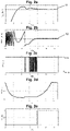
- Measured values and control signals from an inventive method for synchronizing the generator 3 with the power supply network 4 are by Figures 2a to 2e shown, where (as in Figure 2a is shown) an internal combustion engine 2 with a coupled generator 3 is accelerated from standstill until a desired generator speed is reached.
- Figure 2a shows the behavior of the generator speed along the synchronization time with the power supply network 4.
- Figure 2c shows a control signal of the control or regulating unit 6 for the ignition point of at least one cylinder unit 9 of the internal combustion engine 2, ie a control signal for determining the ignition point.
- this ignition timing is given in relation to a rotation angle of the crankshaft of the internal combustion engine 2 before a top dead center (as is common in the prior art).
- Fig. 2d shows a control or regulation signal of the control or regulation unit 6 with regard to a throttle valve of the internal combustion engine 2, the diagram showing an opening of the throttle valve between "1" (fully open) and "0" (fully closed).
- Figure 2e shows a control or regulation signal of the control or regulation unit 6 for the electrical connection 10 of the generator 3 to the power supply network 4, with a distinction being made between a closed connection "1" (control signal for closing the electrical connection 10) and an open connection "0". becomes.
- the connection 10 of the generator 3 to the power supply network 4 is established as soon as the phase angle difference is stabilized in a further tolerance range 12 for an acceptable phase angle difference (connection criterion).
- Fig. 2d Further can be recognized by Fig. 2d that at the beginning of the synchronization the throttle cap is slightly opened. This opening makes it possible to increase the speed of the internal combustion engine 2 when the ignition point corresponds to the nominal ignition point t nom and to reduce the speed when the ignition point corresponds to the changed ignition point t temp . As a result, better response behavior of the control can be achieved during synchronization.
- control or regulation unit 6 connects the generator 3 to the power supply network 4 via the electrical connection 10 and the control or regulation unit 6 can switch to a normal operating mode for the genset 1 to be changed.
- connection criterion includes, for example, that the generator speed (see Figure 2a ) is in a definable tolerance range 11 and that the phase angle difference (see Figure 2a ) is in a further definable tolerance range 12.
- the throttle valve is continuously opened in order to increase the power of the internal combustion engine 2 and thus the power supplied to the power supply network 4.
Landscapes
- Engineering & Computer Science (AREA)
- Chemical & Material Sciences (AREA)
- Combustion & Propulsion (AREA)
- Mechanical Engineering (AREA)
- General Engineering & Computer Science (AREA)
- Power Engineering (AREA)
- Signal Processing (AREA)
- Ignition Installations For Internal Combustion Engines (AREA)
- Electrical Control Of Ignition Timing (AREA)
Applications Claiming Priority (1)
| Application Number | Priority Date | Filing Date | Title |
|---|---|---|---|
| DE102021105547.4A DE102021105547B4 (de) | 2021-03-08 | 2021-03-08 | Verfahren zum Synchronisieren eines Generators mit einem Stromversorgungsnetz |
Publications (2)
| Publication Number | Publication Date |
|---|---|
| EP4056832A1 true EP4056832A1 (fr) | 2022-09-14 |
| EP4056832B1 EP4056832B1 (fr) | 2026-04-29 |
Family
ID=80623594
Family Applications (1)
| Application Number | Title | Priority Date | Filing Date |
|---|---|---|---|
| EP22159341.1A Active EP4056832B1 (fr) | 2021-03-08 | 2022-03-01 | Procédé de synchronisation d'un générateur avec un réseau d'alimentation électrique |
Country Status (3)
| Country | Link |
|---|---|
| US (1) | US11876379B2 (fr) |
| EP (1) | EP4056832B1 (fr) |
| DE (1) | DE102021105547B4 (fr) |
Families Citing this family (1)
| Publication number | Priority date | Publication date | Assignee | Title |
|---|---|---|---|---|
| DE102021119328B3 (de) * | 2021-07-26 | 2022-10-20 | Rolls-Royce Solutions GmbH | Verfahren zum Betreiben eines Generatorsatzes, Einrichtung zum Betreiben eines Generatorsatzes und Generatorsatz |
Citations (5)
| Publication number | Priority date | Publication date | Assignee | Title |
|---|---|---|---|---|
| US20120175876A1 (en) * | 2009-05-20 | 2012-07-12 | Pendray John R | Control of an engine-driven generator to address transients of an electrical power grid connected thereto |
| EP2651000A2 (fr) | 2012-03-22 | 2013-10-16 | Alstom Technology Ltd | Procédé de synchronisation d'un générateur avec un réseau |
| WO2017051156A1 (fr) * | 2015-09-24 | 2017-03-30 | Cummins Power Generation Limited | Systèmes et procédés permettant un démarrage à froid rapide |
| EP2433355B2 (fr) * | 2009-05-20 | 2017-10-04 | Cummins Power Generation IP, Inc. | Appareil, des systèmes et méthodes pour répondre aux transitoires de charge electrique, des défauts électriques et des perturbations dans un réseau électrique |
| EP3561988A1 (fr) | 2018-04-24 | 2019-10-30 | Innio Jenbacher GmbH & Co OG | Synchronisation de réseau rapide |
Family Cites Families (7)
| Publication number | Priority date | Publication date | Assignee | Title |
|---|---|---|---|---|
| JP3308050B2 (ja) * | 1993-07-19 | 2002-07-29 | 株式会社デンソー | 内燃機関のトルク制御装置 |
| AT509558B1 (de) * | 2010-01-19 | 2012-09-15 | Ge Jenbacher Gmbh & Co Ohg | Stationäre kraftanlage |
| US9720395B2 (en) * | 2014-03-04 | 2017-08-01 | Nec Corporation | Synchronization control for reconnecting microgrid to main grid after islanding |
| JP6405866B2 (ja) * | 2014-10-08 | 2018-10-17 | スズキ株式会社 | エンジン制御装置 |
| JP2017133395A (ja) * | 2016-01-26 | 2017-08-03 | 愛三工業株式会社 | エンジンの吸気温度制御装置 |
| JP6836444B2 (ja) * | 2017-03-30 | 2021-03-03 | 本田技研工業株式会社 | 発電機システム |
| DE102017124709B3 (de) | 2017-10-23 | 2018-12-27 | Maximilian Geisberger | Stromaggregat zur Einspeisung von Energie in ein elektrisches Energieversorgungsnetz und Verfahren hierzu |
-
2021
- 2021-03-08 DE DE102021105547.4A patent/DE102021105547B4/de active Active
-
2022
- 2022-03-01 EP EP22159341.1A patent/EP4056832B1/fr active Active
- 2022-03-04 US US17/687,472 patent/US11876379B2/en active Active
Patent Citations (5)
| Publication number | Priority date | Publication date | Assignee | Title |
|---|---|---|---|---|
| US20120175876A1 (en) * | 2009-05-20 | 2012-07-12 | Pendray John R | Control of an engine-driven generator to address transients of an electrical power grid connected thereto |
| EP2433355B2 (fr) * | 2009-05-20 | 2017-10-04 | Cummins Power Generation IP, Inc. | Appareil, des systèmes et méthodes pour répondre aux transitoires de charge electrique, des défauts électriques et des perturbations dans un réseau électrique |
| EP2651000A2 (fr) | 2012-03-22 | 2013-10-16 | Alstom Technology Ltd | Procédé de synchronisation d'un générateur avec un réseau |
| WO2017051156A1 (fr) * | 2015-09-24 | 2017-03-30 | Cummins Power Generation Limited | Systèmes et procédés permettant un démarrage à froid rapide |
| EP3561988A1 (fr) | 2018-04-24 | 2019-10-30 | Innio Jenbacher GmbH & Co OG | Synchronisation de réseau rapide |
Also Published As
| Publication number | Publication date |
|---|---|
| US20220294230A1 (en) | 2022-09-15 |
| US11876379B2 (en) | 2024-01-16 |
| EP4056832B1 (fr) | 2026-04-29 |
| DE102021105547A1 (de) | 2022-09-08 |
| DE102021105547B4 (de) | 2023-09-28 |
Similar Documents
| Publication | Publication Date | Title |
|---|---|---|
| EP2649287B1 (fr) | Procédé pour faire fonctionner un moteur à combustion interne assisté par un moteur électrique, et moteur à combustion interne | |
| DE102016011069B4 (de) | Verfahren zum Betreiben einer Antriebseinrichtung sowie entsprechende Antriebseinrichtung | |
| DE19935826B4 (de) | Drehmomentsteuerung für Direkteinspritzer mit Hilfe einer zusätzlichen Drehmomentvorrichtung | |
| DE19581041C2 (de) | Verfahren zum Steuern des Zündzeitpunktes von Verbrennungsmotoren | |
| EP3015688B1 (fr) | Procede destine au fonctionnement d'un moteur a combustion interne | |
| EP2977596B1 (fr) | Moteur a combustion interne dote d'un dispositif de reglage | |
| AT509558B1 (de) | Stationäre kraftanlage | |
| DE112014006571B4 (de) | Kraftmaschinenstart-Steuervorrichtung | |
| DE102014200740A1 (de) | Verfahren und Regel- und/oder Steuereinrichtung zum Betrieb einer Windenergieanlage und/oder eines Windparks sowie Windenergieanlage und Windpark | |
| DE112012007094B4 (de) | Controller zum Starten einer Fahrzeug-Direkteinspritzungsmaschine | |
| DE102004057282A1 (de) | Verbrennungsmotor-Diagnosesystem | |
| DE102016202343A1 (de) | Verfahren und Vorrichtung zur Steuerung einer Brennkraftmaschine | |
| AT508410B1 (de) | Schwingungskompensierter freikolbenmotor | |
| DE10164789B4 (de) | Verfahren und Vorrichtung zur Voraktivierung mindestens eines elektrischen Aufladegeräts in einem Kraftfahrzeug | |
| DE102013215924B4 (de) | Verfahren zur Lastgleichstellung von Zylindern einer Brennkraftmaschine und Brennkraftmaschine | |
| DE112015001743T5 (de) | Zündvorrichtung für eine Verbrennungskraftmaschine | |
| DE102009047219A1 (de) | Verfahren und Vorrichtung zum Betreiben eines Verbrennungsmotors | |
| EP4056832B1 (fr) | Procédé de synchronisation d'un générateur avec un réseau d'alimentation électrique | |
| EP1090221B1 (fr) | Procede de fonctionnement d'un moteur a combustion interne, notamment pour un vehicule automobile | |
| DE102017209485B4 (de) | Steuereinheit und Steuerverfahren für einen Verbrennungsmotor | |
| DE102011101846A1 (de) | Verfahren und Antivibrationsregelungseinrichtung zum Ausgleichen von durch eine Verbrennungskraftmaschine erzeugte Vibrations-Schwingungen | |
| DE4334864A1 (de) | Verfahren und Vorrichtung zur Steuerung einer Brennkraftmaschine | |
| DE102016203237A1 (de) | Verfahren und Vorrichtung zur Steuerung einer Brennkraftmaschine | |
| EP2396528A2 (fr) | Procédé de régulation d'un moteur à combustion interne | |
| EP3896270B1 (fr) | Moteur à combustion interne |
Legal Events
| Date | Code | Title | Description |
|---|---|---|---|
| PUAI | Public reference made under article 153(3) epc to a published international application that has entered the european phase |
Free format text: ORIGINAL CODE: 0009012 |
|
| STAA | Information on the status of an ep patent application or granted ep patent |
Free format text: STATUS: THE APPLICATION HAS BEEN PUBLISHED |
|
| AK | Designated contracting states |
Kind code of ref document: A1 Designated state(s): AL AT BE BG CH CY CZ DE DK EE ES FI FR GB GR HR HU IE IS IT LI LT LU LV MC MK MT NL NO PL PT RO RS SE SI SK SM TR |
|
| STAA | Information on the status of an ep patent application or granted ep patent |
Free format text: STATUS: REQUEST FOR EXAMINATION WAS MADE |
|
| 17P | Request for examination filed |
Effective date: 20230302 |
|
| RBV | Designated contracting states (corrected) |
Designated state(s): AL AT BE BG CH CY CZ DE DK EE ES FI FR GB GR HR HU IE IS IT LI LT LU LV MC MK MT NL NO PL PT RO RS SE SI SK SM TR |
|
| P01 | Opt-out of the competence of the unified patent court (upc) registered |
Effective date: 20230614 |
|
| STAA | Information on the status of an ep patent application or granted ep patent |
Free format text: STATUS: EXAMINATION IS IN PROGRESS |
|
| 17Q | First examination report despatched |
Effective date: 20250107 |
|
| GRAP | Despatch of communication of intention to grant a patent |
Free format text: ORIGINAL CODE: EPIDOSNIGR1 |
|
| STAA | Information on the status of an ep patent application or granted ep patent |
Free format text: STATUS: GRANT OF PATENT IS INTENDED |
|
| GRAS | Grant fee paid |
Free format text: ORIGINAL CODE: EPIDOSNIGR3 |
|
| INTG | Intention to grant announced |
Effective date: 20260122 |
|
| GRAA | (expected) grant |
Free format text: ORIGINAL CODE: 0009210 |
|
| STAA | Information on the status of an ep patent application or granted ep patent |
Free format text: STATUS: THE PATENT HAS BEEN GRANTED |
|
| AK | Designated contracting states |
Kind code of ref document: B1 Designated state(s): AL AT BE BG CH CY CZ DE DK EE ES FI FR GB GR HR HU IE IS IT LI LT LU LV MC MK MT NL NO PL PT RO RS SE SI SK SM TR |
|
| REG | Reference to a national code |
Ref country code: CH Ref legal event code: F10 Free format text: ST27 STATUS EVENT CODE: U-0-0-F10-F00 (AS PROVIDED BY THE NATIONAL OFFICE) Effective date: 20260429 Ref country code: GB Ref legal event code: FG4D Free format text: NOT ENGLISH |