EP4056859A1 - Procédé de fonctionnement d'un agrégat de tuyauterie, ensemble d'atténuation des vibrations d'une unité de pompe couplée à un agrégat de tuyauterie et unité de pompe - Google Patents
Procédé de fonctionnement d'un agrégat de tuyauterie, ensemble d'atténuation des vibrations d'une unité de pompe couplée à un agrégat de tuyauterie et unité de pompe Download PDFInfo
- Publication number
- EP4056859A1 EP4056859A1 EP21162309.5A EP21162309A EP4056859A1 EP 4056859 A1 EP4056859 A1 EP 4056859A1 EP 21162309 A EP21162309 A EP 21162309A EP 4056859 A1 EP4056859 A1 EP 4056859A1
- Authority
- EP
- European Patent Office
- Prior art keywords
- pump unit
- pipework
- base plate
- aggregate
- foundation
- Prior art date
- Legal status (The legal status is an assumption and is not a legal conclusion. Google has not performed a legal analysis and makes no representation as to the accuracy of the status listed.)
- Granted
Links
Images


Classifications
-
- F—MECHANICAL ENGINEERING; LIGHTING; HEATING; WEAPONS; BLASTING
- F04—POSITIVE - DISPLACEMENT MACHINES FOR LIQUIDS; PUMPS FOR LIQUIDS OR ELASTIC FLUIDS
- F04D—NON-POSITIVE-DISPLACEMENT PUMPS
- F04D29/00—Details, component parts, or accessories
- F04D29/66—Combating cavitation, whirls, noise, vibration or the like; Balancing
- F04D29/669—Combating cavitation, whirls, noise, vibration or the like; Balancing especially adapted for liquid pumps
-
- F—MECHANICAL ENGINEERING; LIGHTING; HEATING; WEAPONS; BLASTING
- F04—POSITIVE - DISPLACEMENT MACHINES FOR LIQUIDS; PUMPS FOR LIQUIDS OR ELASTIC FLUIDS
- F04D—NON-POSITIVE-DISPLACEMENT PUMPS
- F04D15/00—Control, e.g. regulation, of pumps, pumping installations or systems
-
- F—MECHANICAL ENGINEERING; LIGHTING; HEATING; WEAPONS; BLASTING
- F04—POSITIVE - DISPLACEMENT MACHINES FOR LIQUIDS; PUMPS FOR LIQUIDS OR ELASTIC FLUIDS
- F04D—NON-POSITIVE-DISPLACEMENT PUMPS
- F04D29/00—Details, component parts, or accessories
- F04D29/60—Mounting; Assembling; Disassembling
- F04D29/605—Mounting; Assembling; Disassembling specially adapted for liquid pumps
-
- F—MECHANICAL ENGINEERING; LIGHTING; HEATING; WEAPONS; BLASTING
- F05—INDEXING SCHEMES RELATING TO ENGINES OR PUMPS IN VARIOUS SUBCLASSES OF CLASSES F01-F04
- F05D—INDEXING SCHEME FOR ASPECTS RELATING TO NON-POSITIVE-DISPLACEMENT MACHINES OR ENGINES, GAS-TURBINES OR JET-PROPULSION PLANTS
- F05D2260/00—Function
- F05D2260/85—Starting
-
- F—MECHANICAL ENGINEERING; LIGHTING; HEATING; WEAPONS; BLASTING
- F05—INDEXING SCHEMES RELATING TO ENGINES OR PUMPS IN VARIOUS SUBCLASSES OF CLASSES F01-F04
- F05D—INDEXING SCHEME FOR ASPECTS RELATING TO NON-POSITIVE-DISPLACEMENT MACHINES OR ENGINES, GAS-TURBINES OR JET-PROPULSION PLANTS
- F05D2270/00—Control
- F05D2270/30—Control parameters, e.g. input parameters
- F05D2270/303—Temperature
Definitions
- stiffness and/or damping of support of the base plate of the pump unit on the foundation is restored to the state prevailing in the transient state.
- An assembly for attenuation of vibration of a pump unit coupled to a pipework comprising a centrifugal pump and a motor assembled on a base plate, the pump unit being supported resiliently on a foundation using a resilient support, which resilient support is resilient several directions.
- the assembly comprises a retainer means configured movable between a first position suppressing relative movement between the foundation and the base plate for increasing stiffness and/or damping and/or damping of support of the base plate of the pump unit on the foundation, a second position being neutral in influencing to relative movement between the foundation and the base plate.
- the base plate is supported on the foundation by several vertical legs wherein the resilient support is arranged between the leg and the base plate, and the retainer means are arranged to selectably supress relative movement between the leg and the base plate in the plane of the base plate.
- the retainer means are provided with a body part, and pusher part adjustably attached to the body part, wherein the relative movement between the leg and the base plate is suppressible by bringing the pusher part against either one of the base plate or the leg while the body part being attached to either one of the base plate or the leg.
- body part is attached to the base plate and the pusher part is configured to adjustably push against the leg.
- the pusher part comprises a screw bar and the body part comprises a threaded hole to which the screw bar is attached, and that the pusher part is provided with a resilient head at an end of the screw bar.
- the resilient support are compression springs.
- a pump unit comprising an assembly for attenuation of vibration according to the invention.
- base plate means a generally planar structure on which a centrifugal pump and its motor are assembled.
- the base plate may be a framework which is constructed of multiple beams arranged to form the planar structure.
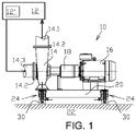
- the pump unit comprises a resilient support 24 in the base plate 20, such that the pump unit 10 is supported resiliently on the foundation 22.
- the resilient support 24 is resilient several directions.
- the resilient support may comprise one of, or a combination of a spring, resilient block, such as a rubber block, vibration damper, such as viscose damper, or alike.
- the resilient support is a compression spring 25.
- the resilient support has a main compression direction which is bearing the load caused by the mass of the pump unit 10. The main compression direction is therefore substantially vertical direction transverse to the plane or the base plate 20.
- the pump 14 is connected to the pipework aggregate without any bellows, that is using simple flange joint 14.2 directly to respective feed pipe 14.1 and return pipe 14.3. Such a flange joint may be considered as a rigid coupling. At least the flange joint 14.2. is considerably stiffer than the resilient support 24.
- FIG. 2 shows a side view of a pump unit 10 according to an embodiment of the invention.
- FIG. 3 shows a left-side end view of the Figure 2 .
- FIG. 5 shows a sectional view V-V marked in the figure 3 which is in turn shown in the Figure 5 .
- the pump unit 10 comprises an assembly 26 for attenuation of vibration of a pump unit to selectably effect on the resilient support 24 in the base plate 20 and vibration characteristics of the pump unit 10.
- the assembly 26 comprises adjustable retainer means 28 for increasing stiffness and/or damping of support of the base plate of the pump unit on the foundation.
- the retainer means 28 can be selectably activated for effecting on the stiffness and/or damping of support of the base plate and deactivated. In addition to mere on-off action of being activate or passive, the stiffness is adjustable by adjusting the force by which the retainer means 28 effects.
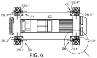
- FIG. 7 there is shown an enlarged view A in the figure 6 , which shows one of the resilient supports 24 in connection with which two retainer means 28 are arranged.
- the retainer means 28 are arranged as pairs in which the retainer means 28.1'-28.1" effect in opposite directions to each other.
- the first pair of retainer means 28.1'-28.1" is arranged to effect in the direction of the selected direction, and a second pair of retainer means 28.3' - 28.3" is arranged to effect in the direction perpendicularly to the selected direction.
- the retainer means 28 are provided with a body part 32, and a pusher part 34 adjustably attached to the body part 32, wherein the relative movement between the leg 30 and the base plate 20 is suppressible by bringing the pusher part 34 against either one of the base plate 20 or the leg 32 while the body part 32 being attached to either one of the base plate 20 or the leg 32.
- the pusher part 34 is brought against the other one of the base plate 20 or the leg 32.
- the body part 32 of the retainer means 28 is attached by screws to the base plate 20 and the pusher part 34 is brought against a surface of the leg 32.
- the pusher part is configured to adjustably push against the leg.
- the pusher part is configured to be selectably activated, by bring it against the leg 32, and deactivated by detaching the pusher part 34 from the leg 32, and when activated the pressing force of the pusher part is adjustable.
- the pusher part 34 comprises a screw bar and the body part comprises a threaded hole 36 to which the screw bar is attached so as to provide adjustable longitudinal movement of the screw bar by rotation thereof.
- the pusher part 34 is provided with a resilient head 38 at an end of the screw bar 34.
- the surface in the leg, against which the pushed part 34 is pushing can be provided with an optional, additional counter part 40, by means of the characteristics of the support can be further controlled.
- the counter part 40 may be for a resilient block or a plate.
- the counter part 40 may be arranged in connection with one or more, or all of the pusher parts 34.
- stiffness and/or damping of support of the base plate of the pump unit on the foundation is increased, such that stiffness and/or damping of support of the pump unit 10 on the foundation is ruled in addition to the resilient support, by means of the pusher part 34, as is depicted in the figure 7 .
- the retainer means 28 it is possible to minimize excessive vibration of the pump unit 10 induced by excitations from the pipework.
- the resilient support results in advanced operation during the start-up stage compensating heat expansion of the pipework aggregate, while during the steady state operation, when the operational temperature has been reached, increased stiffness and/or damping is brought by the pusher part minimizing excessive vibration of the pump unit 10.
- the method may include a step of setting a target operational temperature to the process fluid and/or the pipework aggregate, and acquiring a measured temperature of the process fluid and/or the pipework aggregate, and in case the measured temperature is lower than the target operational temperature the pipework aggregate is in a transient state operation, and in case the measured temperature is equal to or higher than the target operational temperature, the pipework aggregate is in a steady state operation.
- Each one of the retainer means 28 effects in one direction in the plane of the base plate 20.
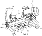
- the assembly comprises a pole 42 which is attached to the foundation 20 similarly to the legs 30 of the pump unit 10. In practise the surface at the end of the pole 42 in the figure 9 is attached to the foundation.
- the pole extends upwardly from the foundation into the plane of the base plate 20 between its structural beams.
- the body part 48 is provided with a pusher screw 50 by means of which the position of the wedge part 46 can be changed. Movement of the wedge part 46 tightens the wedge-shaped space between the support block 44 and the body part 48, and this way effects on the stiffness and/or damping of support of the base plate 20.
- the contact may be arranged as a gliding contact by arranging a suitable glide part to either one, or both of the surface.
- FIG 11 discloses a view of a pump unit 10 from beneath the pump unit 10 according to another embodiment of the invention.
- the pump unit 10 comprises an alternative assembly 26 for attenuation of vibration of a pump unit to selectably effect on the resilient support 24 in the base plate 20 and vibration characteristics of the pump unit 10.
- the assembly 26 comprises four retainer means 28 for increasing stiffness and/or damping of support of the base plate of the pump unit on the foundation.
- vibration of the pump unit is analysed during the transient state operation and if at least one direction of vibration, which has vibration amplitude greater than a pre-set limit value of the amplitude, is determined, stiffness and/or damping of the base plate of the pump unit is increased in at least the determined direction of vibration.
- stiffness and/or damping of support of the base plate of the pump unit on the foundation is increased by arranging a mechanical retainer means to suppress relative movement between the base plate and the foundation in the determined direction of vibration.
- Change of the fluid characteristics is change of temperature and operation is steady state operation when the temperature has reached a predetermined temperature level.
Landscapes
- Engineering & Computer Science (AREA)
- Mechanical Engineering (AREA)
- General Engineering & Computer Science (AREA)
- Vibration Prevention Devices (AREA)
- Structures Of Non-Positive Displacement Pumps (AREA)
Priority Applications (2)
| Application Number | Priority Date | Filing Date | Title |
|---|---|---|---|
| EP21162309.5A EP4056859B1 (fr) | 2021-03-12 | 2021-03-12 | Procédé de fonctionnement d'un agrégat de tuyauterie, et unité de pompe avec un ensemble d'atténuation des vibrations d'une unité de pompe couplée à un agrégat de tuyauterie |
| FIEP21162309.5T FI4056859T3 (fi) | 2021-03-12 | 2021-03-12 | Menetelmä putkistokokonaisuuden käyttämiseksi ja pumppuyksikkö käsittäen kokoonpanon putkistokokonaisuuteen liitetyn pumppuyksikön värähtelyn vaimentamiseksi |
Applications Claiming Priority (1)
| Application Number | Priority Date | Filing Date | Title |
|---|---|---|---|
| EP21162309.5A EP4056859B1 (fr) | 2021-03-12 | 2021-03-12 | Procédé de fonctionnement d'un agrégat de tuyauterie, et unité de pompe avec un ensemble d'atténuation des vibrations d'une unité de pompe couplée à un agrégat de tuyauterie |
Publications (2)
| Publication Number | Publication Date |
|---|---|
| EP4056859A1 true EP4056859A1 (fr) | 2022-09-14 |
| EP4056859B1 EP4056859B1 (fr) | 2025-01-29 |
Family
ID=74873581
Family Applications (1)
| Application Number | Title | Priority Date | Filing Date |
|---|---|---|---|
| EP21162309.5A Active EP4056859B1 (fr) | 2021-03-12 | 2021-03-12 | Procédé de fonctionnement d'un agrégat de tuyauterie, et unité de pompe avec un ensemble d'atténuation des vibrations d'une unité de pompe couplée à un agrégat de tuyauterie |
Country Status (2)
| Country | Link |
|---|---|
| EP (1) | EP4056859B1 (fr) |
| FI (1) | FI4056859T3 (fr) |
Cited By (1)
| Publication number | Priority date | Publication date | Assignee | Title |
|---|---|---|---|---|
| WO2023041594A1 (fr) * | 2021-09-17 | 2023-03-23 | Grundfos Holding A/S | Dispositif et procédé de commande de vibrations opérationnelles d'une pompe ou d'un ensemble pompe |
Citations (6)
| Publication number | Priority date | Publication date | Assignee | Title |
|---|---|---|---|---|
| DE29603890U1 (de) * | 1996-03-02 | 1996-05-30 | Ktr Kupplungstechnik Gmbh, 48432 Rheine | Dämpfungsring zur Geräuschreduzierung mit Sicherungsvorrichtung |
| US20140271242A1 (en) * | 2013-03-13 | 2014-09-18 | Agilent Technologies, Inc. | Vibration/noise management in a scroll compressor |
| CN108931086A (zh) * | 2018-08-22 | 2018-12-04 | 珠海格力电器股份有限公司 | 一种压缩机振动的控制方法、装置及机组 |
| CN110500262A (zh) * | 2019-09-12 | 2019-11-26 | 珠海格力电器股份有限公司 | 一种定频压缩机的减振机构、方法、定频压缩机及空调 |
| CN111364771A (zh) * | 2020-03-27 | 2020-07-03 | 上海建工一建集团有限公司 | 混凝土泵送作业安全控制系统、其布置方法和控制方法 |
| KR20200087114A (ko) | 2020-07-09 | 2020-07-20 | 주식회사 동아펌프 | 원심펌프의 진동흡수 및 지지를 위한 설치구조 |
Family Cites Families (1)
| Publication number | Priority date | Publication date | Assignee | Title |
|---|---|---|---|---|
| JPH06129487A (ja) * | 1992-10-13 | 1994-05-10 | Hitachi Ltd | ばね定数可変型制振装置 |
-
2021
- 2021-03-12 FI FIEP21162309.5T patent/FI4056859T3/fi active
- 2021-03-12 EP EP21162309.5A patent/EP4056859B1/fr active Active
Patent Citations (6)
| Publication number | Priority date | Publication date | Assignee | Title |
|---|---|---|---|---|
| DE29603890U1 (de) * | 1996-03-02 | 1996-05-30 | Ktr Kupplungstechnik Gmbh, 48432 Rheine | Dämpfungsring zur Geräuschreduzierung mit Sicherungsvorrichtung |
| US20140271242A1 (en) * | 2013-03-13 | 2014-09-18 | Agilent Technologies, Inc. | Vibration/noise management in a scroll compressor |
| CN108931086A (zh) * | 2018-08-22 | 2018-12-04 | 珠海格力电器股份有限公司 | 一种压缩机振动的控制方法、装置及机组 |
| CN110500262A (zh) * | 2019-09-12 | 2019-11-26 | 珠海格力电器股份有限公司 | 一种定频压缩机的减振机构、方法、定频压缩机及空调 |
| CN111364771A (zh) * | 2020-03-27 | 2020-07-03 | 上海建工一建集团有限公司 | 混凝土泵送作业安全控制系统、其布置方法和控制方法 |
| KR20200087114A (ko) | 2020-07-09 | 2020-07-20 | 주식회사 동아펌프 | 원심펌프의 진동흡수 및 지지를 위한 설치구조 |
Cited By (1)
| Publication number | Priority date | Publication date | Assignee | Title |
|---|---|---|---|---|
| WO2023041594A1 (fr) * | 2021-09-17 | 2023-03-23 | Grundfos Holding A/S | Dispositif et procédé de commande de vibrations opérationnelles d'une pompe ou d'un ensemble pompe |
Also Published As
| Publication number | Publication date |
|---|---|
| FI4056859T3 (fi) | 2025-04-28 |
| EP4056859B1 (fr) | 2025-01-29 |
Similar Documents
| Publication | Publication Date | Title |
|---|---|---|
| AU2007228927B2 (en) | Device and method for mounting a turbine engine | |
| EP2400119B1 (fr) | Système de jeu des extrémités d'aubes de rotor et de dynamique d'arbre dans un moteur à turbine à gaz | |
| KR100756416B1 (ko) | 배관의 진동저감장치 | |
| CN104105847B (zh) | 单机室型蒸汽轮机及单轴型联合循环发电装置 | |
| EP4056859B1 (fr) | Procédé de fonctionnement d'un agrégat de tuyauterie, et unité de pompe avec un ensemble d'atténuation des vibrations d'une unité de pompe couplée à un agrégat de tuyauterie | |
| CN105927708B (zh) | 一种可调节刚度和阻尼的主动减振支承 | |
| US8616517B2 (en) | Turbomachine foot unit | |
| KR101504852B1 (ko) | 제 1 및 제 2 수동 유압 구성요소를 구비한 압연기의 진동 감쇠 시스템 | |
| CN103429928A (zh) | 具有模块化柔性纽带和可变间隙的阻尼器 | |
| Morosi et al. | Experimental investigations of active air bearings | |
| JPH0115735B2 (fr) | ||
| EP0315416B1 (fr) | Dispositif d'oscillation pour l'amortissement des vibrations | |
| JPH05149365A (ja) | 能動的振動制御システムにおける弾性連接棒 | |
| KR20110004252U (ko) | 경량구조의 변위제한형 방진스프링마운트 | |
| JPS58121336A (ja) | 弾性支持された機械の軸整合方法 | |
| EP3559461B1 (fr) | Actionneur passif pour supprimer une vibration d'une colonne montante d'un pompe verticale, pompe verticale et procédé de réhabilitation d'une pompe verticale | |
| Pourmohammadi et al. | A novel approach to vibration control in fluid-conveying pipes using piezoelectric actuators | |
| US20250020122A1 (en) | Device and method for controlling operational vibrations of a pump or pump assembly | |
| EP4048912B1 (fr) | Support de palier et pompe | |
| JP2008188692A (ja) | ロール加工装置 | |
| KR200364417Y1 (ko) | 배관 지지장치 | |
| KR100349722B1 (ko) | 배관계 진동흡수 장치 | |
| JP4982272B2 (ja) | アクティブ除振マウント機構 | |
| CN114563096A (zh) | 一种抗震式双金属温度计 | |
| EP2469044B1 (fr) | Module pour turbine à vapeur |
Legal Events
| Date | Code | Title | Description |
|---|---|---|---|
| PUAI | Public reference made under article 153(3) epc to a published international application that has entered the european phase |
Free format text: ORIGINAL CODE: 0009012 |
|
| STAA | Information on the status of an ep patent application or granted ep patent |
Free format text: STATUS: THE APPLICATION HAS BEEN PUBLISHED |
|
| AK | Designated contracting states |
Kind code of ref document: A1 Designated state(s): AL AT BE BG CH CY CZ DE DK EE ES FI FR GB GR HR HU IE IS IT LI LT LU LV MC MK MT NL NO PL PT RO RS SE SI SK SM TR |
|
| STAA | Information on the status of an ep patent application or granted ep patent |
Free format text: STATUS: REQUEST FOR EXAMINATION WAS MADE |
|
| 17P | Request for examination filed |
Effective date: 20230314 |
|
| RBV | Designated contracting states (corrected) |
Designated state(s): AL AT BE BG CH CY CZ DE DK EE ES FI FR GB GR HR HU IE IS IT LI LT LU LV MC MK MT NL NO PL PT RO RS SE SI SK SM TR |
|
| RIC1 | Information provided on ipc code assigned before grant |
Ipc: F04D 29/60 20060101ALI20240710BHEP Ipc: F04D 15/00 20060101ALI20240710BHEP Ipc: F04D 29/66 20060101AFI20240710BHEP |
|
| GRAP | Despatch of communication of intention to grant a patent |
Free format text: ORIGINAL CODE: EPIDOSNIGR1 |
|
| STAA | Information on the status of an ep patent application or granted ep patent |
Free format text: STATUS: GRANT OF PATENT IS INTENDED |
|
| INTG | Intention to grant announced |
Effective date: 20240822 |
|
| GRAS | Grant fee paid |
Free format text: ORIGINAL CODE: EPIDOSNIGR3 |
|
| P01 | Opt-out of the competence of the unified patent court (upc) registered |
Free format text: CASE NUMBER: APP_61913/2024 Effective date: 20241119 |
|
| GRAA | (expected) grant |
Free format text: ORIGINAL CODE: 0009210 |
|
| STAA | Information on the status of an ep patent application or granted ep patent |
Free format text: STATUS: THE PATENT HAS BEEN GRANTED |
|
| AK | Designated contracting states |
Kind code of ref document: B1 Designated state(s): AL AT BE BG CH CY CZ DE DK EE ES FI FR GB GR HR HU IE IS IT LI LT LU LV MC MK MT NL NO PL PT RO RS SE SI SK SM TR |
|
| REG | Reference to a national code |
Ref country code: GB Ref legal event code: FG4D |
|
| REG | Reference to a national code |
Ref country code: CH Ref legal event code: EP |
|
| REG | Reference to a national code |
Ref country code: DE Ref legal event code: R096 Ref document number: 602021025283 Country of ref document: DE |
|
| REG | Reference to a national code |
Ref country code: IE Ref legal event code: FG4D |
|
| PGFP | Annual fee paid to national office [announced via postgrant information from national office to epo] |
Ref country code: AT Payment date: 20250417 Year of fee payment: 5 |
|
| REG | Reference to a national code |
Ref country code: FI Ref legal event code: FGE |
|
| REG | Reference to a national code |
Ref country code: NL Ref legal event code: MP Effective date: 20250129 |
|
| PG25 | Lapsed in a contracting state [announced via postgrant information from national office to epo] |
Ref country code: NL Free format text: LAPSE BECAUSE OF FAILURE TO SUBMIT A TRANSLATION OF THE DESCRIPTION OR TO PAY THE FEE WITHIN THE PRESCRIBED TIME-LIMIT Effective date: 20250129 |
|
| PG25 | Lapsed in a contracting state [announced via postgrant information from national office to epo] |
Ref country code: RS Free format text: LAPSE BECAUSE OF FAILURE TO SUBMIT A TRANSLATION OF THE DESCRIPTION OR TO PAY THE FEE WITHIN THE PRESCRIBED TIME-LIMIT Effective date: 20250429 |
|
| PG25 | Lapsed in a contracting state [announced via postgrant information from national office to epo] |
Ref country code: PL Free format text: LAPSE BECAUSE OF FAILURE TO SUBMIT A TRANSLATION OF THE DESCRIPTION OR TO PAY THE FEE WITHIN THE PRESCRIBED TIME-LIMIT Effective date: 20250129 |
|
| PG25 | Lapsed in a contracting state [announced via postgrant information from national office to epo] |
Ref country code: ES Free format text: LAPSE BECAUSE OF FAILURE TO SUBMIT A TRANSLATION OF THE DESCRIPTION OR TO PAY THE FEE WITHIN THE PRESCRIBED TIME-LIMIT Effective date: 20250129 |
|
| REG | Reference to a national code |
Ref country code: LT Ref legal event code: MG9D |
|
| PG25 | Lapsed in a contracting state [announced via postgrant information from national office to epo] |
Ref country code: NO Free format text: LAPSE BECAUSE OF FAILURE TO SUBMIT A TRANSLATION OF THE DESCRIPTION OR TO PAY THE FEE WITHIN THE PRESCRIBED TIME-LIMIT Effective date: 20250429 Ref country code: IS Free format text: LAPSE BECAUSE OF FAILURE TO SUBMIT A TRANSLATION OF THE DESCRIPTION OR TO PAY THE FEE WITHIN THE PRESCRIBED TIME-LIMIT Effective date: 20250529 |
|
| REG | Reference to a national code |
Ref country code: AT Ref legal event code: MK05 Ref document number: 1763690 Country of ref document: AT Kind code of ref document: T Effective date: 20250129 |
|
| PG25 | Lapsed in a contracting state [announced via postgrant information from national office to epo] |
Ref country code: HR Free format text: LAPSE BECAUSE OF FAILURE TO SUBMIT A TRANSLATION OF THE DESCRIPTION OR TO PAY THE FEE WITHIN THE PRESCRIBED TIME-LIMIT Effective date: 20250129 |
|
| PG25 | Lapsed in a contracting state [announced via postgrant information from national office to epo] |
Ref country code: LV Free format text: LAPSE BECAUSE OF FAILURE TO SUBMIT A TRANSLATION OF THE DESCRIPTION OR TO PAY THE FEE WITHIN THE PRESCRIBED TIME-LIMIT Effective date: 20250129 Ref country code: PT Free format text: LAPSE BECAUSE OF FAILURE TO SUBMIT A TRANSLATION OF THE DESCRIPTION OR TO PAY THE FEE WITHIN THE PRESCRIBED TIME-LIMIT Effective date: 20250529 |
|
| PG25 | Lapsed in a contracting state [announced via postgrant information from national office to epo] |
Ref country code: BG Free format text: LAPSE BECAUSE OF FAILURE TO SUBMIT A TRANSLATION OF THE DESCRIPTION OR TO PAY THE FEE WITHIN THE PRESCRIBED TIME-LIMIT Effective date: 20250129 Ref country code: GR Free format text: LAPSE BECAUSE OF FAILURE TO SUBMIT A TRANSLATION OF THE DESCRIPTION OR TO PAY THE FEE WITHIN THE PRESCRIBED TIME-LIMIT Effective date: 20250430 |
|
| PG25 | Lapsed in a contracting state [announced via postgrant information from national office to epo] |
Ref country code: AT Free format text: LAPSE BECAUSE OF FAILURE TO SUBMIT A TRANSLATION OF THE DESCRIPTION OR TO PAY THE FEE WITHIN THE PRESCRIBED TIME-LIMIT Effective date: 20250129 |
|
| PG25 | Lapsed in a contracting state [announced via postgrant information from national office to epo] |
Ref country code: SE Free format text: LAPSE BECAUSE OF FAILURE TO SUBMIT A TRANSLATION OF THE DESCRIPTION OR TO PAY THE FEE WITHIN THE PRESCRIBED TIME-LIMIT Effective date: 20250129 |
|
| REG | Reference to a national code |
Ref country code: DE Ref legal event code: R119 Ref document number: 602021025283 Country of ref document: DE |
|
| PG25 | Lapsed in a contracting state [announced via postgrant information from national office to epo] |
Ref country code: SM Free format text: LAPSE BECAUSE OF FAILURE TO SUBMIT A TRANSLATION OF THE DESCRIPTION OR TO PAY THE FEE WITHIN THE PRESCRIBED TIME-LIMIT Effective date: 20250129 |
|
| PG25 | Lapsed in a contracting state [announced via postgrant information from national office to epo] |
Ref country code: DK Free format text: LAPSE BECAUSE OF FAILURE TO SUBMIT A TRANSLATION OF THE DESCRIPTION OR TO PAY THE FEE WITHIN THE PRESCRIBED TIME-LIMIT Effective date: 20250129 |
|
| PG25 | Lapsed in a contracting state [announced via postgrant information from national office to epo] |
Ref country code: MC Free format text: LAPSE BECAUSE OF FAILURE TO SUBMIT A TRANSLATION OF THE DESCRIPTION OR TO PAY THE FEE WITHIN THE PRESCRIBED TIME-LIMIT Effective date: 20250129 |
|
| PG25 | Lapsed in a contracting state [announced via postgrant information from national office to epo] |
Ref country code: IT Free format text: LAPSE BECAUSE OF FAILURE TO SUBMIT A TRANSLATION OF THE DESCRIPTION OR TO PAY THE FEE WITHIN THE PRESCRIBED TIME-LIMIT Effective date: 20250129 |
|
| PG25 | Lapsed in a contracting state [announced via postgrant information from national office to epo] |
Ref country code: CZ Free format text: LAPSE BECAUSE OF FAILURE TO SUBMIT A TRANSLATION OF THE DESCRIPTION OR TO PAY THE FEE WITHIN THE PRESCRIBED TIME-LIMIT Effective date: 20250129 Ref country code: EE Free format text: LAPSE BECAUSE OF FAILURE TO SUBMIT A TRANSLATION OF THE DESCRIPTION OR TO PAY THE FEE WITHIN THE PRESCRIBED TIME-LIMIT Effective date: 20250129 |
|
| PG25 | Lapsed in a contracting state [announced via postgrant information from national office to epo] |
Ref country code: RO Free format text: LAPSE BECAUSE OF FAILURE TO SUBMIT A TRANSLATION OF THE DESCRIPTION OR TO PAY THE FEE WITHIN THE PRESCRIBED TIME-LIMIT Effective date: 20250129 |
|
| REG | Reference to a national code |
Ref country code: CH Ref legal event code: H13 Free format text: ST27 STATUS EVENT CODE: U-0-0-H10-H13 (AS PROVIDED BY THE NATIONAL OFFICE) Effective date: 20251023 |
|
| PG25 | Lapsed in a contracting state [announced via postgrant information from national office to epo] |
Ref country code: SK Free format text: LAPSE BECAUSE OF FAILURE TO SUBMIT A TRANSLATION OF THE DESCRIPTION OR TO PAY THE FEE WITHIN THE PRESCRIBED TIME-LIMIT Effective date: 20250129 |
|
| PG25 | Lapsed in a contracting state [announced via postgrant information from national office to epo] |
Ref country code: LU Free format text: LAPSE BECAUSE OF NON-PAYMENT OF DUE FEES Effective date: 20250312 |
|
| PLBE | No opposition filed within time limit |
Free format text: ORIGINAL CODE: 0009261 |
|
| STAA | Information on the status of an ep patent application or granted ep patent |
Free format text: STATUS: NO OPPOSITION FILED WITHIN TIME LIMIT |
|
| REG | Reference to a national code |
Ref country code: BE Ref legal event code: MM Effective date: 20250331 |
|
| GBPC | Gb: european patent ceased through non-payment of renewal fee |
Effective date: 20250429 |
|
| 26N | No opposition filed |
Effective date: 20251030 |
|
| PG25 | Lapsed in a contracting state [announced via postgrant information from national office to epo] |
Ref country code: DE Free format text: LAPSE BECAUSE OF NON-PAYMENT OF DUE FEES Effective date: 20251001 |
|
| PG25 | Lapsed in a contracting state [announced via postgrant information from national office to epo] |
Ref country code: GB Free format text: LAPSE BECAUSE OF NON-PAYMENT OF DUE FEES Effective date: 20250429 |
|
| PG25 | Lapsed in a contracting state [announced via postgrant information from national office to epo] |
Ref country code: FR Free format text: LAPSE BECAUSE OF NON-PAYMENT OF DUE FEES Effective date: 20250329 |
|
| PG25 | Lapsed in a contracting state [announced via postgrant information from national office to epo] |
Ref country code: BE Free format text: LAPSE BECAUSE OF NON-PAYMENT OF DUE FEES Effective date: 20250331 |
|
| PG25 | Lapsed in a contracting state [announced via postgrant information from national office to epo] |
Ref country code: CH Free format text: LAPSE BECAUSE OF NON-PAYMENT OF DUE FEES Effective date: 20250331 |
|
| PG25 | Lapsed in a contracting state [announced via postgrant information from national office to epo] |
Ref country code: IE Free format text: LAPSE BECAUSE OF NON-PAYMENT OF DUE FEES Effective date: 20250312 |
|
| PGFP | Annual fee paid to national office [announced via postgrant information from national office to epo] |
Ref country code: FI Payment date: 20260323 Year of fee payment: 6 |