EP4057453B1 - Hochvoltmanagementsystem insbesondere für fahrzeugenergiespeicher - Google Patents
Hochvoltmanagementsystem insbesondere für fahrzeugenergiespeicher Download PDFInfo
- Publication number
- EP4057453B1 EP4057453B1 EP21208812.4A EP21208812A EP4057453B1 EP 4057453 B1 EP4057453 B1 EP 4057453B1 EP 21208812 A EP21208812 A EP 21208812A EP 4057453 B1 EP4057453 B1 EP 4057453B1
- Authority
- EP
- European Patent Office
- Prior art keywords
- contact
- terminal housing
- receiving space
- socket
- socket contact
- Prior art date
- Legal status (The legal status is an assumption and is not a legal conclusion. Google has not performed a legal analysis and makes no representation as to the accuracy of the status listed.)
- Active
Links
Images

Classifications
-
- H—ELECTRICITY
- H01—ELECTRIC ELEMENTS
- H01R—ELECTRICALLY-CONDUCTIVE CONNECTIONS; STRUCTURAL ASSOCIATIONS OF A PLURALITY OF MUTUALLY-INSULATED ELECTRICAL CONNECTING ELEMENTS; COUPLING DEVICES; CURRENT COLLECTORS
- H01R13/00—Details of coupling devices of the kinds covered by groups H01R12/70 or H01R24/00 - H01R33/00
- H01R13/62—Means for facilitating engagement or disengagement of coupling parts or for holding them in engagement
- H01R13/629—Additional means for facilitating engagement or disengagement of coupling parts, e.g. aligning or guiding means, levers, gas pressure electrical locking indicators, manufacturing tolerances
- H01R13/631—Additional means for facilitating engagement or disengagement of coupling parts, e.g. aligning or guiding means, levers, gas pressure electrical locking indicators, manufacturing tolerances for engagement only
- H01R13/6315—Additional means for facilitating engagement or disengagement of coupling parts, e.g. aligning or guiding means, levers, gas pressure electrical locking indicators, manufacturing tolerances for engagement only allowing relative movement between coupling parts, e.g. floating connection
-
- H—ELECTRICITY
- H01—ELECTRIC ELEMENTS
- H01M—PROCESSES OR MEANS, e.g. BATTERIES, FOR THE DIRECT CONVERSION OF CHEMICAL ENERGY INTO ELECTRICAL ENERGY
- H01M10/00—Secondary cells; Manufacture thereof
- H01M10/42—Methods or arrangements for servicing or maintenance of secondary cells or secondary half-cells
- H01M10/425—Structural combination with electronic components, e.g. electronic circuits integrated to the outside of the casing
-
- H—ELECTRICITY
- H01—ELECTRIC ELEMENTS
- H01R—ELECTRICALLY-CONDUCTIVE CONNECTIONS; STRUCTURAL ASSOCIATIONS OF A PLURALITY OF MUTUALLY-INSULATED ELECTRICAL CONNECTING ELEMENTS; COUPLING DEVICES; CURRENT COLLECTORS
- H01R13/00—Details of coupling devices of the kinds covered by groups H01R12/70 or H01R24/00 - H01R33/00
- H01R13/02—Contact members
- H01R13/15—Pins, blades or sockets having separate spring member for producing or increasing contact pressure
- H01R13/187—Pins, blades or sockets having separate spring member for producing or increasing contact pressure with spring member in the socket
-
- H—ELECTRICITY
- H01—ELECTRIC ELEMENTS
- H01R—ELECTRICALLY-CONDUCTIVE CONNECTIONS; STRUCTURAL ASSOCIATIONS OF A PLURALITY OF MUTUALLY-INSULATED ELECTRICAL CONNECTING ELEMENTS; COUPLING DEVICES; CURRENT COLLECTORS
- H01R2101/00—One pole
-
- H—ELECTRICITY
- H01—ELECTRIC ELEMENTS
- H01R—ELECTRICALLY-CONDUCTIVE CONNECTIONS; STRUCTURAL ASSOCIATIONS OF A PLURALITY OF MUTUALLY-INSULATED ELECTRICAL CONNECTING ELEMENTS; COUPLING DEVICES; CURRENT COLLECTORS
- H01R2201/00—Connectors or connections adapted for particular applications
- H01R2201/26—Connectors or connections adapted for particular applications for vehicles
Definitions
- the present invention relates to a battery management system (BMS), in particular for vehicle energy storage devices, such as vehicle batteries.
- BMS battery management system
- Battery management system or simply battery management is a measure, but usually an electronic circuit, which is used to monitor, control and protect batteries in vehicles.
- the BMS also includes automatic switching the power supply depending on whether a charger or a limited power data interface is connected.
- pluggable terminals are also used for the high-voltage terminals.
- These are solutions in which several electrical contact sockets are integrated in a complex housing, which are plugged together with the mating housing of the battery management system during assembly. However, this is done blindly, as the contact sockets in the housing are not visible to the user during the plugging process. Since solutions with a non-symmetrical interface also exist or are required, the plugging process is a challenge.
- the dimensions of a typical battery management system are quite large and so are the system-related tolerances that a housing and the components arranged in it have. This also creates a tolerance problem with the position tolerances of the contact sockets.
- the contact sockets must be aligned as precisely as possible with the corresponding positions of the contact plugs on the opposite side and, on the other hand, they must also be located in defined positions relative to the housing. The position of the contacts also determines, among other things, the insertion and removal forces of the plug system.
- Floating contacts or connecting elements are also known from the documents US 2020/119493 A1 , US 7 077 697 B2 and US 9 270 052 B1 known.
- the present invention is therefore based on the object of overcoming the aforementioned disadvantages and proposing a flexible, universally applicable and cost-effective solution for battery management systems (BMS).
- BMS battery management systems
- a basic idea of the invention is to mount the individual contact sockets flexibly and, so to speak, "floating" and, in particular, to make their busbar supply line flexible.
- a terminal housing according to claim 1 is proposed for this purpose.
- the terminal housing has a terminal area with cylindrical socket contacts (generally contacts) for electrical connection to mating contacts of a battery management system (BMS), wherein at least one contact holder is provided which is stationary in the housing and on which the cylindrical socket contacts are mounted so as to be movable (and thus radially movable) at least transversely to the plug-in direction.
- BMS battery management system
- the respective contact holder is formed from a plurality of elastically deflectable spring arms which together form a common receiving space for receiving a socket contact and which rest with their free spring arm end against an outer casing of the socket contact received in the receiving space.
- socket contact several spring arms extend away from the contact holder in the direction of insertion and form a common bearing for a socket contact, which can be accommodated in it "floating".
- the socket contact can be deflected radially, even with blind insertion and the system-related tolerances, and the two mating contacts (socket contact and, for example, high-voltage pin) "find" each other and can be brought together.
- the degree of radial mobility is at least 10% - 15% of the external diameter of the socket contact.
- approximately 2 mm of radial play is possible in each radial deflection for a socket contact with a diameter of 2 cm.
- the multiple spring arms of a contact receptacle of a contact holder are arranged in relation to one another in such a way that they together form a cylindrical receiving space for a cylindrical socket contact.
- the contact is then centrally received therein and can be held in a radially movable manner by means of the flexibly deflectable spring arms.
- the spring arms it is also conceivable to design the spring arms as snap hooks, the end of which engages in a groove on the contact, so that a fixed axial bearing is achieved.
- the contact holder has a passage opening for the respective socket contact and the socket contact extends at least with a partial section through the passage opening, while another partial section is held by the respective spring arms.
- a further aspect of the present invention relates to the connection of the contacts as such.
- the cylindrical socket contact is connected at its front end opposite the plug-in side to an electrically conductive flexible busbar, in particular an S-shaped, U-shaped, wave-shaped or curved busbar, which is further preferably firmly electrically connected to a busbar with its other connection end, in particular screwed to it.
- an electrically conductive flexible busbar in particular an S-shaped, U-shaped, wave-shaped or curved busbar, which is further preferably firmly electrically connected to a busbar with its other connection end, in particular screwed to it.
- Conventional cable materials and designs can be used as busbar cables for this purpose.
- the spring arms are bent or cranked inwards at or near their free spring arm end in the direction of the receiving space for the socket contact or have a nose that extends radially inwards in the direction of the receiving space. This results in a defined ring-shaped contact section on which the socket contact is held.
- at least 6, preferably 8 or more spring arms are provided per socket contact.
- the socket contacts are provided as single-pole contact elements, so that each socket contact has its independent function from the other socket contacts and can be positioned at a suitable position on the contact carrier, which allows a high degree of flexibility in the design of such terminal housings.
- the vehicle-side counter-contact e.g. an HV contact pin
- the vehicle-side counter-contact connected to the vehicle battery via a cable
- the contact socket or the high-voltage socket contact is designed accordingly.
- a further aspect of the invention relates to a terminal housing having a terminal area with contact pins for electrical connection with cylindrical high-voltage socket contacts, in which the respective positions of the socket contact and contact pin in the plug system are swapped so that the contact pin is mounted radially movable on the terminal side and the respective corresponding contact socket is on the opposite side.
- FIG. 1 a schematic representation of a partial view of an embodiment of the invention is shown, which is part of a higher-level terminal housing 1, which is also shown in a partial view in the Figure 4 is shown.
- the terminal housing 1 can have a complex shape and be adapted to the application in order to connect it to the vehicle-side interface.
- a terminal area 10 with cylindrical socket contacts 20 is provided in the terminal housing 1, of which only one such socket contact 20 is shown as an example.
- Several of these socket contacts 20 are, as in the Figure 5 shown, arranged in the terminal housing 1.
- the socket contacts 20 are designed for electrical connection with counter contacts 50 of a battery management system (BMS).
- BMS battery management system
- Contact holders 30 are provided in the terminal housing 1, on which the cylindrical socket contacts 20 are mounted.
- the socket contact 20 shown is mounted on the elastically deflectable spring arms 31 so that it can move transversely to the plugging direction S.
- the spring arms form a common receiving space for receiving the socket contact 20.
- the spring arms 30 On their free spring arm end 32, the spring arms 30 have a nose 33 which protrudes in the direction of the receiving space.
- the socket contact 20 is therefore mounted on the ring-shaped section on the noses 33.
- the spring arms 30 are connected to the retaining flange 34 and extend in the plugging direction S.
- the retaining flange 34 has a through-opening for the respective socket contact 20.
- the socket contact 20 extends with an upper section through the passage opening, while another, central section, located approximately in the middle of the contact 20 as viewed in the plugging direction, is held by the respective spring arms 31.
- the connection of the cylindrical socket contact 20 to a busbar (busbar line) 24 is also shown.
- the socket contact 20 has an electrically conductive flexible busbar connection at its front end 23 opposite the plug-in side 22, to which the busbar 24 is connected.
- the course of the busbar 24 shows a wave shape.
- it is electrically screwed to a busbar 26.
- busbar lines 24 are shown, each of which leads to the four socket contacts 20. All of these busbar lines 24 are designed with a tolerance compensation section in the form of a downwardly bent wave.
- the counter contact 50 is shown, which is connected to the vehicle battery via a cable and has a guide 51 extending in the plugging direction and designed as a contact protection, as well as a central contact pin 52, which is cylindrically surrounded by the contact protection.
- the contact socket is enclosed by the electrically insulating contact protection when plugged in.
- the invention is not limited in its implementation to the preferred embodiments given above. Rather, a number of variants are conceivable which make use of the solution presented even in fundamentally different embodiments.
Landscapes
- Engineering & Computer Science (AREA)
- Microelectronics & Electronic Packaging (AREA)
- Manufacturing & Machinery (AREA)
- Chemical & Material Sciences (AREA)
- Chemical Kinetics & Catalysis (AREA)
- Electrochemistry (AREA)
- General Chemical & Material Sciences (AREA)
- Details Of Connecting Devices For Male And Female Coupling (AREA)
Description
- Die vorliegende Erfindung betrifft ein Batteriemanagementsystem (BMS) insbesondere für Fahrzeugenergiespeicher, wie Fahrzeugbatterien.
- Bekannte Batteriemanagementsystem (BMS) oder einfach das Batteriemanagement ist eine Maßnahme, meist jedoch eine elektronische Schaltung, welche zur Überwachung, Regelung und zum Schutz von Akkumulatoren in Fahrzeugen dient.
- Dabei handelt es sich z. B. um Ladezustandserkennung, Tiefentladeschutz, Überladeschutz oder auch um komplexe Systeme mit Datenschnittstellen. In vielen mobilen Geräten umfasst das BMS auch die automatische Umschaltung der Stromversorgung je nachdem, ob ein Ladegerät oder eine begrenzt speisefähige Datenschnittstelle angeschlossen ist.
- Bei der Topologie von solchen Systemen werden auch steckbare Terminals für die Hochvolt-Terminals eingesetzt. Dabei handelt es sich um Lösungen, bei denen mehrere elektrische Kontaktbuchsen in einem komplexen Gehäuse integriert sind, die mit dem Gegengehäuse des Batteriemanagementsystems bei der Montage zusammen gesteckt werden. Hierzu erfolgt aber ein blindes Stecken, da bei dem Steckvorgang die Kontaktbuchsen in dem Gehäuse vom Verwender nicht gesehen werden. Da zusätzlich auch Lösungen mit einem nicht symmetrischen Interface existieren oder benötigt werden, gestaltet sich der Steckvorgang als eine Herausforderung.
- Ferner sind die Abmessungen eines typischen Batteriemanagementsystems recht groß und demnach auch die systembedingten Toleranzen, die ein Gehäuse und die darin angeordneten Komponenten aufweisen. Somit tritt auch ein Toleranzproblem bei den Positionstoleranzen der Kontaktbuchsen auf. Die Kontaktbuchsen müssen einerseits möglichst exakt zu den korrespondierenden Positionen der Kontaktstecker auf der Gegenseite fluchten und andererseits auch gegenüber dem Gehäuse an definierten Positionen sitzen. Die Lage der Kontakte bestimmt unter anderem auch die Steck-und Ziehkräfte des Stecksystems.
- In den Druckschriften
DE 3 536 142 A1 ,DE 6002 6208 T2 ,DE 68913828 T2 ,DE 7047251 B ,EP8938562 A2 undWO 2003103104A1 finden sich jeweils Lösungen betreffend das "blinde" Stecken ohne Sicht auf das Interface des Systems bei der Montage und betreffend der Toleranzproblematik. Diese Lösungen lassen sich aber nicht ohne weiteres und auch nicht mit dem gewünschten Erfolg auf ein Gehäuse und den Terminal-Bereich eines Batteriemanagementsystems (BMS) übertragen. Bereits aufgrund der teilweise sehr komplexen Geometrie bedarf es einer anderen, insbesondere flexiblen Lösung, wir die vorbesagten Probleme überwunden werden können. - Schwimmend gelagerte Kontakte oder Verbindungselemente sind zudem aus den Schriften
US 2020/119493 A1 ,US 7 077 697 B2 undUS 9 270 052 B1 - Der vorliegenden Erfindung liegt daher die Aufgabe zugrunde, vorbesagte Nachteile zu überwinden und eine flexible, universell verwendbare und kostengünstige Lösung für Batteriemanagementsysteme (BMS) vorzuschlagen.
- Ein Grundgedanke der Erfindung ist es dabei, die einzelnen Kontaktbuchsen flexible und sozusagen "schwimmend" zu Lagern und dabei insbesondere auch deren Busbar-Zuleitung flexible zu gestalten.
- Erfindungsgemäß wird hierzu ein Terminalgehäuse gemäß Anspruch 1 vorgeschlagen. Das Terminalgehäuse weist einen Terminalbereich mit zylinderförmigen Buchsenkontakten (allgemein Kontakten) zur elektrischen Verbindung mit Gegenkontakten eines Batteriemanagementsystems (BMS) auf, wobei wenigstens eine stationär im Gehäuse angebrachte Kontakthalterung vorgesehen ist, an denen die zylinderförmigen Buchsenkontakte zumindest quer zur Steckrichtung beweglich (somit radial beweglich) gelagert sind. Zur Erzielung der besagten radialen Beweglichkeit ist hierzu die jeweilige Kontakthalterung aus je einer Mehrzahl an elastisch auslenkbaren Federarmen ausgebildet, die zusammen jeweils einen gemeinsamen Aufnahmeraum für die Aufnahme eines Buchsenkontaktes ausbilden und mit ihrem freien Federarmende gegen einen Außenmantel des in dem Aufnahmeraum aufgenommenen Buchsenkontaktes anliegen.
- Anders ausgedrückt erstrecken sich mehrere Federarme in Steckrichtung von der Kontakthalterung weg und bilden ein gemeinsames Lager für einen Buchsenkontakt, der darin "schwimmend" aufgenommen werden kann. Beim Zusammenstecken mit dem Gegenstecker kann auch bei blindem Stecken und den systembedingten Toleranzen der Buchsenkontakt radial ausgelenkt werden und die beiden Gegenkontakte (Buchsenkontakt und z. B. Hochvoltpin) "finden" sich und können zusammen geführt werden.
- In einer bevorzugten Ausgestaltung ist vorgesehen, dass das Maß für die radiale Beweglichkeit mindestens 10 % - 15% des Außen-Durchmessers des Buchsenkontaktes beträgt. So werden z. B. etwa 2 mm Radialspiel in jede radiale Auslenkung für einen Buchsenkontakt mit einem Durchmesser von 2 cm ermöglicht.
- In einer besonders vorteilhaften Ausführungsform der Erfindung ist vorgesehen, dass die mehreren Federarme einer Kontaktaufnahme einer Kontakthalterung jeweils so zueinander angeordnet sind, dass diese gemeinsam einen zylinderförmigen Aufnahmeraum für einen zylinderförmigen Buchsenkontakt ausbilden. Der Kontakt wird dann darin zentral aufgenommen und kann radial beweglich mittels der flexibel auslenkbaren Federarme gehalten werden. Denkbar ist es auch, die Federarme als Schnapphaken auszubilden, deren Ende ein eine Nut am Kontakt eingreift, so dass eine feste Axiallagerung erzielt wird.
- In ebenfalls bevorzugter Weise ist vorgesehen, dass die Kontakthalterung jeweils eine Durchtrittsöffnung für den jeweiligen Buchsenkontakt aufweist und sich der Buchsenkontakt zumindest mit einem Teilabschnitt durch die Durchtrittsöffnung hindurch erstreckt, während ein anderer Teilabschnitt von den jeweiligen Federarmen gehalten wird.
- Ein weiterer Aspekt der vorliegenden Erfindung betrifft den Anschluss der Kontakte als solche. Bevorzugt ist hierzu vorgesehen, dass der zylinderförmige Buchsenkontakt an seinem der Steckseite gegenüberliegenden stirnseitigen Ende mit einem elektrisch leitenden flexiblen Busbar verbunden ist, insbesondere einem S-förmig, U-förmig, wellenförmig oder einem gebogenen Busbar, der weiter vorzugsweise mit seinem anderen Anschlussende elektrisch an einer Stromschiene fest verbunden insbesondere mit dieser verschraubt ist. Dies hat den Vorteil, dass der beweglich Kontakt auch über den Anschlussbereich über eine Beweglichkeit verfügt. Als Busbarleitungen können hierzu herkömmliche Leitungsmaterialen und Ausführungen verwendet werden.
- In einer ebenfalls vorteilhaften Ausführungsform der Erfindung ist vorgesehen, dass der jeweilige Busbar quer zur Steckrichtung vom jeweiligen Buchsenkontakt weggeführt ist. Somit entsteht sozusagen eine 90°-Anschlussart, bei der der Busbaranschluss quer zur Steckrichtung weg montiert ist und dadurch die radiale Beweglichkeit begünstig bzw. unterstützt ist.
- Weiter vorteilhaft ist es, wenn die Federarme an oder nahe zu ihrem freien Federarmende in Richtung des Aufnahmeraums für den Buchsenkontakt gebogen oder nach innen gekröpft ausgebildet sind oder eine Nase aufweisen, die sich radial nach innen in Richtung des Aufnahmeraums erstreckt. Dadurch ergibt sich ein definierter ringförmiger Anlageabschnitt an denen der Buchsenkontakt gehalten wird. Bevorzugt sind wenigstens 6, vorzugsweise 8 oder mehr Federarme je Buchsenkontakt vorgesehen.
- In einer bevorzugten Ausgestaltung der Erfindung sind die Buchsenkontakte als jeweils einpolige Kontaktelemente bereitgestellt, so dass jeder Buchsenkontakt sozusagen seine unabhängige Funktion von den anderen Buchsenkontakten hat und an einer geeigneten Position am Kontaktträger positioniert werden kann, was eine hohe Flexibilität bei dem Design von solchen Terminalgehäusen erlaubt.
- Weiter hat es sich als Vorteil gezeigt, wenn der mit der Fahrzeugbatterie über eine Leitung verbundene fahrzeugseitige Gegenkontakt (z. B. ein HV-Kontaktpin) eine sich in Steckrichtung erstreckende, als Berührschutz ausgeführte außenliegende Führung um den jeweiligen Kontaktpin herum aufweist, der ausgebildet ist, mit der Kontaktbuchse in elektrischen Kontakt gebracht zu werden, wobei dann der Berührschutz die Kontaktbuchse im gesteckten Zustand berührsicher umschließt und bevorzugt auch im nicht gesteckten Zustand ein Berührschutz vorhanden ist, der bis zur Spitze des Kontaktpins reicht. Daraus folgt, dass die Kontaktbuchse bzw. der Hochvolt-Buchsenkontakt entsprechend ausgebildet ist.
- Die Erfindung wurde zunächst in ihrer vorteilhaften Form beschrieben, bei der die Buchsenkontakte wie beschrieben an dem Kontaktträger schwimmend gelagert sind. Denkbar wäre aber auch eine sogenannte kinematische Umkehr und Vertauschen der Kontaktpositionen. Daher betrifft ein weiterer Aspekt der Erfindung ein Terminalgehäuse aufweisend einen Terminalbereich mit Kontaktpins zur elektrischen Verbindung mit zylinderförmigen Hochvolt-Buchsenkontakten, bei welchem entsprechend die jeweilige Position von Buchsenkontakt und Kontaktpin im Stecksystem vertauscht sind, so dass der Kontaktpin auf der Terminalseite radialbeweglich gelagert ist und sich die jeweilige korrespondierende Kontaktbuchse auf der Gegenseite befindet.
- Andere vorteilhafte Weiterbildungen der Erfindung sind in den Unteransprüchen gekennzeichnet bzw. werden nachstehend zusammen mit der Beschreibung der bevorzugten Ausführung der Erfindung anhand der Figuren näher dargestellt.
- Es zeigen:
- Fig.1
- eine schematische Darstellung einer Teilansicht einer Ausführungsform der Erfindung;
- Fig.2
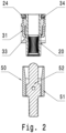
- eine schematische Schnittansicht ergänzt mit einem schematisch dargestellten Gegenstecker;
- Fig.3
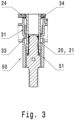
- eine Schnittansicht durch ein Ausführungsbeispiel im gesteckten Zustand;
- Fig. 4
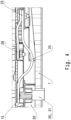
- eine Teil-Ansicht des Terminalgehäuses mit einer Kontaktbuchse, die via einer Busbarleitung elektrisch mit dem Stromverteiler verbunden ist und
- Fig. 5
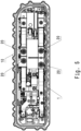
- eine beispielhafte Draufsicht auf eine Schnittstelle eines Terminalgehäuses mit vier Buchsenkontakten.
- Im Folgenden wird die Erfindung anhand einer beispielhaften Ausführungsform mit Bezug auf die
Figuren 1 bis 5 näher beschrieben, wobei gleiche Bezugszeichen auf gleiche funktionale und/oder strukturelle Merkmale in den Figuren hinweisen. - Zunächst ist in der
Figur 1 eine schematische Darstellung einer Teilansicht einer Ausführungsform der Erfindung gezeigt, die Teil eines übergeordneten Terminalgehäuses 1 ist, welches ebenfalls in einer ausschnittsweisen Ansicht in derFigur 4 gezeigt ist. Das Terminalgehäuse 1 kann dabei komplex geformt sind und auf die Applikation entsprechend angepasst, um dieses mit der fahrzeugseitigen Schnittstelle zu verbinden. - Mit Bezug auf die
Figuren 4 und5 ist zu erkennen, dass im Terminalgehäuse 1 ein Terminalbereich 10 mit zylinderförmigen Buchsenkontakten 20 vorgesehen ist, wovon beispielhaft nur ein solcher Buchsenkontakt 20 gezeigt ist. Mehrere dieser Buchsenkontakte 20 sind, wie in derFigur 5 gezeigt, im Terminalgehäuse 1 angeordnet. - Die Buchsenkontakte 20 sind zur elektrischen Verbindung mit Gegenkontakten 50 eines Batteriemanagementsystem (BMS) ausgestaltet. Im Terminalgehäuse 1 sind Kontakthalterungen 30 vorgesehen, an denen die zylinderförmigen Buchsenkontakten 20 gelagert sind. Ein solches Beispiel ist in den
Figuren 1 bis 3 näher gezeigt. Der dargestellte Buchsenkontakt 20 ist quer zur Steckrichtung S beweglich an den elastisch auslenkbaren Federarmen 31 gelagert. Die Federarme bilden hierzu einen gemeinsamen Aufnahmeraum zur Aufnahme des Buchsenkontaktes 20. An ihrem freien Federarmende 32 besitzen die Federarme 30 eine Nase 33, die in Richtung des Aufnahmeraums hervorsteht. Der Buchsenkontakt 20 lagert demnach an dem ringförmigen Abschnitt an den Nasen 33. - Die Federarme 30 sind an dem Halteflansch 34 angebunden und erstrecken sich in Steckrichtung S. Der Halteflansch 34 besitzt eine Durchtrittsöffnung für den jeweiligen Buchsenkontakt 20. Wie in den Ansichten der
Figuren 1 und3 zu erkennen, erstreckt sich der Buchsenkontakt 20 mit einem oberen Teilabschnitt durch die Durchtrittsöffnung hindurch, während ein anderer, zentraler in etwa in der Mitte des Kontakts 20 in Steckrichtung betrachtet, liegender Teilabschnitt von den jeweiligen Federarmen 31 gehalten wird. - In der Ansicht der
Figur 4 ist auch die Verbindung des zylinderförmigen Buchsenkontakts 20 mit einer Busbar (Busbarleitung) 24 gezeigt. Der Buchsenkontakt 20 verfügt an seinem der Steckseite 22 gegenüberliegenden stirnseitigen Ende 23 über einen elektrisch leitenden flexiblen Busbaranschluss an dem der Busbar 24 verbunden ist. Der Verlauf des Busbar 24 zeigt eine Wellenform. An seinem anderen Anschlussende 25 ist dieser elektrisch an einer Stromschiene 26 verschraubt. In derFigur 5 sind weitere Busbarleitungen 24 dargestellt, die jeweils zu den vier Buchsenkontakten 20 führen. Sämtliche dieser Busbarleitungen 24 sind mit einem Toleranzausgleichabschnitt in Form einer nach untern gebogenen Welle ausgeführt. - In den
Figuren 2 und3 ist jeweils der mit der Fahrzeugbatterie über eine Leitung verbundene Gegenkontakt 50 gezeigt, der eine sich in Steckrichtung erstreckende als Berührschutz ausgeführte Führung 51 besitzt, sowie einen zentralen Kontaktpin 52, der von dem Berührschutz zylindrisch umgeben ist. In derFigur 3 ist ersichtlich, dass die Kontaktbuchse im gesteckten Zustand vom elektrisch isolierenden Berührschutz umschlossen ist. - Die Erfindung beschränkt sich in ihrer Ausführung nicht auf die vorstehend angegebenen bevorzugten Ausführungsbeispiele. Vielmehr ist eine Anzahl von Varianten denkbar, welche von der dargestellten Lösung auch bei grundsätzlich anders gearteten Ausführungen Gebrauch macht.
Claims (11)
- Terminalgehäuse (1) aufweisend einen Terminalbereich (10) mit zylinderförmigen Hochvolt-Buchsenkontakten (20) zur elektrischen Verbindung mit Gegenkontakten (50) eines Batteriemanagementsystems (BMS),wobei wenigstens eine stationär im Terminalbereich (10) angebrachte Kontakthalterung (30) vorgesehen ist, an welcher jeweils ein zylinderförmiger Hochvolt-Buchsenkontakt (20) zumindest quer zur Steckrichtung (S) schwimmend beweglich gelagert ist,wobei die jeweilige Kontakthalterung (30) zur Erzielung einer sich aus der Beweglichkeit zumindest quer zur Steckrichtung (S) ergebenden radialen Beweglichkeit aus je einer Mehrzahl an elastisch auslenkbaren Federarmen (31) ausgebildet ist, die zusammen jeweils einen gemeinsamen Aufnahmeraum für die Aufnahme des jeweiligen Hochvolt-Buchsenkontaktes (20) ausbilden und mit ihrem freien Federarmende (32) gegen einen Außenmantel (21) des in dem Aufnahmeraum aufgenommenen Hochvolt-Buchsenkontaktes (20) anliegen, sodass der Hochvolt-Buchsenkontakt (20) in dem Aufnahmeraum schwimmend gelagert und ausgebildet ist, sich bei einem Zusammenführen des Hochvolt-Buchsenkontakts (20) mit einem jeweiligen Gegenkontakt (50) am Gegenkontakt (50) auszurichten.
- Terminalgehäuse (1) nach Anspruch 1, dadurch gekennzeichnet, dass die mehreren Federarme (31) einer Kontakthalterung (30) jeweils so zueinander angeordnet sind, dass diese gemeinsam einen zylinderförmigen Aufnahmeraum für einen Buchsenkontakt (20) ausbilden.
- Terminalgehäuse (1) nach Anspruch 1 oder 2, dadurch gekennzeichnet, dass die Kontakthalterung (30) jeweils eine Durchtrittsöffnung für den jeweiligen Buchsenkontakt (20) aufweist und sich der Buchsenkontakt (20) zumindest mit einem Teilabschnitt durch die Durchtrittsöffnung hindurch erstreckt, während ein anderer Teilabschnitt von den jeweiligen Federarmen (31) gehalten wird.
- Terminalgehäuse (1) nach einem der vorhergehenden Ansprüche, dadurch gekennzeichnet, dass der zylinderförmige Buchsenkontakt (20) an seinem der Steckseite (22) gegenüberliegenden stirnseitigen Ende (23) mit einem elektrisch leitenden flexiblen Busbar (24) verbunden ist, insbesondere einem S-förmig, U-förmig, wellenförmig oder einem gebogenen Busbar (24), der weiter vorzugsweise mit seinem anderen Anschlussende (25) elektrisch an einer Stromschiene (26) fest verbunden insbesondere mit dieser verschraubt ist.
- Terminalgehäuse (1) nach dem vorhergehenden Anspruch, dadurch gekennzeichnet, dass der jeweilige Busbar quer zur Steckrichtung vom jeweiligen Buchsenkontakt (20) weggeführt ist.
- Terminalgehäuse (1) nach einem der vorhergehenden Ansprüche, dadurch gekennzeichnet, dass die radiale Beweglichkeit mindestens 10 % - 15% des Außen-Durchmessers des Buchsenkontaktes (20) beträgt.
- Terminalgehäuse (1) nach einem der vorhergehenden Ansprüche, dadurch gekennzeichnet, dass die Federarme (31) an oder nahe zu ihrem freien Federarmende (32) in Richtung des Aufnahmeraums für den Buchsenkontakt (20) gebogen ausgebildet sind oder eine Nase (33) aufweisen, die sich radial nach innen in Richtung des Aufnahmeraums erstreckt.
- Terminalgehäuse (1) nach einem der vorhergehenden Ansprüche, dadurch gekennzeichnet, dass wenigstens 6, vorzugsweise 8 oder wenigstens 8 Federarme (30) je Buchsenkontakt (20) vorgesehen sind.
- Terminalgehäuse (1) nach einem der vorhergehenden Ansprüche, dadurch gekennzeichnet, dass die Buchsenkontakte (20) einpolige Kontaktelemente darstellen.
- Terminalgehäuse (1) nach einem der vorhergehenden Ansprüche, dadurch gekennzeichnet, dass der Hochvolt-Buchsenkontakt (20) ausgebildet ist, mit dem mit der Fahrzeugbatterie über eine Leitung verbundenen Gegenkontakt (50), welcher eine sich in Steckrichtung erstreckende als Berührschutz ausgeführte Führung (51) um einen Kontaktpin (52) herum aufweist, in elektrischen Kontakt gebracht und durch den Berührschutz (51) im gesteckten Zustand umschlossen zu werden.
- Terminalgehäuse (1) aufweisend einen Terminalbereich (10) mit Kontaktpins (52) zur elektrischen Verbindung mit zylinderförmigen Hochvolt-Buchsenkontakten (20) eines Batteriemanagementsystems (BMS),wobei wenigstens eine stationär im Terminalbereich (10) angebrachte Kontakthalterung (30) vorgesehen ist, an welcher jeweils ein Kontaktpin (52) zumindest quer zur Steckrichtung (S) schwimmend beweglich gelagert ist,wobei die jeweilige Kontakthalterung (30) zur Erzielung einer sich aus der Beweglichkeit zumindest quer zur Steckrichtung (S) ergebenden radialen Beweglichkeit aus je einer Mehrzahl an elastisch auslenkbaren Federarmen (31) ausgebildet ist, die zusammen jeweils einen gemeinsamen Aufnahmeraum für die Aufnahme des jeweiligen Kontaktpins (52) ausbilden und mit ihrem freien Federarmende (32) gegen einen Außenmantel des in dem Aufnahmeraum aufgenommenen Kontaktpins (52) anliegen, sodass der Kontaktpin (52) in dem Aufnahmeraum schwimmend gelagert und ausgebildet ist, sich bei einem Zusammenführen des Kontaktpins (52) mit einem jeweiligen Hochvolt-Buchsenkontakt (20) am Hochvolt-Buchsenkontakt (20) auszurichten.
Applications Claiming Priority (1)
| Application Number | Priority Date | Filing Date | Title |
|---|---|---|---|
| DE102021105914.3A DE102021105914A1 (de) | 2021-03-11 | 2021-03-11 | Hochvoltmanagementsystem insbesondere für Fahrzeugenergiespeicher |
Publications (2)
| Publication Number | Publication Date |
|---|---|
| EP4057453A1 EP4057453A1 (de) | 2022-09-14 |
| EP4057453B1 true EP4057453B1 (de) | 2024-11-06 |
Family
ID=78676510
Family Applications (1)
| Application Number | Title | Priority Date | Filing Date |
|---|---|---|---|
| EP21208812.4A Active EP4057453B1 (de) | 2021-03-11 | 2021-11-17 | Hochvoltmanagementsystem insbesondere für fahrzeugenergiespeicher |
Country Status (2)
| Country | Link |
|---|---|
| EP (1) | EP4057453B1 (de) |
| DE (1) | DE102021105914A1 (de) |
Family Cites Families (12)
| Publication number | Priority date | Publication date | Assignee | Title |
|---|---|---|---|---|
| US4406507A (en) | 1981-06-30 | 1983-09-27 | The Bendix Corporation | Electrical connector insert |
| DE3536142A1 (de) | 1985-10-10 | 1987-04-16 | Opel Adam Ag | Mehrpolige, als steckverbindung ausgebildete elektrische verbindung zwischen zwei gelenkig miteinander verbundenen bauteilen, insbesondere zwischen karosserie und seitentuer von kraftfahrzeugen |
| US4812133A (en) | 1988-06-30 | 1989-03-14 | Amp Incorporated | Floating mounting means for electrical connector assembly |
| GB9715378D0 (en) | 1997-07-23 | 1997-09-24 | Tec Electrical Components Limi | Connector assemblies |
| JP4365949B2 (ja) | 1999-08-25 | 2009-11-18 | モレックス インコーポレイテド | 基板接続用コネクタ |
| US6354890B2 (en) | 2000-03-17 | 2002-03-12 | Delphi Technologies, Inc. | High current sleeve and post terminals |
| TW200409418A (en) | 2002-05-30 | 2004-06-01 | Heyco Products Inc | Connectors for under-cabinet lighting |
| US7077697B2 (en) * | 2004-09-09 | 2006-07-18 | Corning Gilbert Inc. | Snap-in float-mount electrical connector |
| DE102007047251B4 (de) | 2007-10-02 | 2011-07-07 | Amphenol-Tuchel Electronics GmbH, 74080 | Selbstjustierender Gerätesteckverbinder |
| US9379468B2 (en) | 2012-10-26 | 2016-06-28 | Cisco Technology, Inc. | Apparatus and method for allowing alignment mismatch in electrical connections |
| US9270052B1 (en) * | 2015-03-31 | 2016-02-23 | Tyco Electronics Corporation | Pass-through connector system |
| DE202018105926U1 (de) * | 2018-10-16 | 2018-11-02 | Odu Gmbh & Co. Kg | Schwimmender Verbinder |
-
2021
- 2021-03-11 DE DE102021105914.3A patent/DE102021105914A1/de active Pending
- 2021-11-17 EP EP21208812.4A patent/EP4057453B1/de active Active
Also Published As
| Publication number | Publication date |
|---|---|
| EP4057453A1 (de) | 2022-09-14 |
| DE102021105914A1 (de) | 2022-09-15 |
Similar Documents
| Publication | Publication Date | Title |
|---|---|---|
| DE102013209690B4 (de) | HV-Fingerschutz | |
| EP2831957B1 (de) | Sicherungssystem für hochstromanwendungen | |
| DE102011078412B4 (de) | Elektrischer Anschluss zum Aufnehmen eines Steckers | |
| EP2499709B1 (de) | Steckeradapter | |
| EP3104469B1 (de) | Rundsteckverbinder zur datenübertragung hoher datenraten | |
| DE202008013757U1 (de) | Hybrid-Steckverbinder für Daten- und Powerleitungen | |
| EP2957003B1 (de) | Adapter | |
| EP3613110B1 (de) | Baugruppe für ein steckverbinderteil mit einem kontakteinsatz und einem erdungselement | |
| WO2010112516A1 (de) | Abgeschirmte steckverbinderanordnung | |
| DE19638157A1 (de) | Elektrischer Mehrpolstecker | |
| DE102016213757B4 (de) | Steckverbindung zum Koppeln von Hochvoltanschlüssen und System mit einer derartigen Steckverbindung | |
| DE102020211091A1 (de) | Elektrischer Kontaktverbinder sowie Batterie | |
| WO2021027991A1 (de) | Hybridsteckverbinder | |
| EP2345110B1 (de) | Steckverbinder für ein sternvierer-kabel | |
| EP4356485A1 (de) | Berührschutzpin | |
| DE202021101221U1 (de) | Hochvoltmanagementsystem insbesondere für Fahrzeugenergiespeicher | |
| DE102015122868A1 (de) | Mehrfachstecker insbesondere für ein Fahrzeug zum Anschließen eines Koaxialkabels, mit dem Mehrfachstecker verbindbare Buchse, Mehrfachsteckverbindung umfassend einen derartigen Mehrfachstecker und eine derartige Buchse sowie Fahrzeug mit einem solchen Mehrfachstecker | |
| EP4057453B1 (de) | Hochvoltmanagementsystem insbesondere für fahrzeugenergiespeicher | |
| DE102021107921B4 (de) | Elektrisches kabel mit an leitern befestigten, separaten kontaktelementen zur bauraumsparenden anordnung in einem stecksystem | |
| EP4080687B1 (de) | Steckverbinderanordnung und steckverbindung | |
| EP2697869B1 (de) | Steckverbinder mit einem kontaktelement | |
| DE102024114591A1 (de) | Anschlussklemme | |
| DE102020114088B4 (de) | Schirmhülse | |
| EP2073314B1 (de) | Anordnung zum elektrisch leitenden Verbinden von elektrischen Leltern | |
| WO2022218762A1 (de) | Anschlusseinheit |
Legal Events
| Date | Code | Title | Description |
|---|---|---|---|
| PUAI | Public reference made under article 153(3) epc to a published international application that has entered the european phase |
Free format text: ORIGINAL CODE: 0009012 |
|
| STAA | Information on the status of an ep patent application or granted ep patent |
Free format text: STATUS: THE APPLICATION HAS BEEN PUBLISHED |
|
| AK | Designated contracting states |
Kind code of ref document: A1 Designated state(s): AL AT BE BG CH CY CZ DE DK EE ES FI FR GB GR HR HU IE IS IT LI LT LU LV MC MK MT NL NO PL PT RO RS SE SI SK SM TR |
|
| STAA | Information on the status of an ep patent application or granted ep patent |
Free format text: STATUS: REQUEST FOR EXAMINATION WAS MADE |
|
| 17P | Request for examination filed |
Effective date: 20230307 |
|
| RBV | Designated contracting states (corrected) |
Designated state(s): AL AT BE BG CH CY CZ DE DK EE ES FI FR GB GR HR HU IE IS IT LI LT LU LV MC MK MT NL NO PL PT RO RS SE SI SK SM TR |
|
| RIC1 | Information provided on ipc code assigned before grant |
Ipc: H01R 101/00 20060101ALN20240729BHEP Ipc: H01R 13/187 20060101ALN20240729BHEP Ipc: H01R 13/631 20060101AFI20240729BHEP |
|
| GRAP | Despatch of communication of intention to grant a patent |
Free format text: ORIGINAL CODE: EPIDOSNIGR1 |
|
| STAA | Information on the status of an ep patent application or granted ep patent |
Free format text: STATUS: GRANT OF PATENT IS INTENDED |
|
| GRAS | Grant fee paid |
Free format text: ORIGINAL CODE: EPIDOSNIGR3 |
|
| GRAA | (expected) grant |
Free format text: ORIGINAL CODE: 0009210 |
|
| STAA | Information on the status of an ep patent application or granted ep patent |
Free format text: STATUS: THE PATENT HAS BEEN GRANTED |
|
| INTG | Intention to grant announced |
Effective date: 20240911 |
|
| P01 | Opt-out of the competence of the unified patent court (upc) registered |
Free format text: CASE NUMBER: APP_51986/2024 Effective date: 20240916 |
|
| AK | Designated contracting states |
Kind code of ref document: B1 Designated state(s): AL AT BE BG CH CY CZ DE DK EE ES FI FR GB GR HR HU IE IS IT LI LT LU LV MC MK MT NL NO PL PT RO RS SE SI SK SM TR |
|
| REG | Reference to a national code |
Ref country code: GB Ref legal event code: FG4D Free format text: NOT ENGLISH |
|
| REG | Reference to a national code |
Ref country code: CH Ref legal event code: EP |
|
| REG | Reference to a national code |
Ref country code: DE Ref legal event code: R096 Ref document number: 502021005710 Country of ref document: DE |
|
| REG | Reference to a national code |
Ref country code: IE Ref legal event code: FG4D Free format text: LANGUAGE OF EP DOCUMENT: GERMAN |
|
| REG | Reference to a national code |
Ref country code: NL Ref legal event code: FP |
|
| REG | Reference to a national code |
Ref country code: LT Ref legal event code: MG9D |
|
| PG25 | Lapsed in a contracting state [announced via postgrant information from national office to epo] |
Ref country code: HR Free format text: LAPSE BECAUSE OF FAILURE TO SUBMIT A TRANSLATION OF THE DESCRIPTION OR TO PAY THE FEE WITHIN THE PRESCRIBED TIME-LIMIT Effective date: 20241106 Ref country code: PT Free format text: LAPSE BECAUSE OF FAILURE TO SUBMIT A TRANSLATION OF THE DESCRIPTION OR TO PAY THE FEE WITHIN THE PRESCRIBED TIME-LIMIT Effective date: 20250306 Ref country code: IS Free format text: LAPSE BECAUSE OF FAILURE TO SUBMIT A TRANSLATION OF THE DESCRIPTION OR TO PAY THE FEE WITHIN THE PRESCRIBED TIME-LIMIT Effective date: 20250306 |
|
| PG25 | Lapsed in a contracting state [announced via postgrant information from national office to epo] |
Ref country code: FI Free format text: LAPSE BECAUSE OF FAILURE TO SUBMIT A TRANSLATION OF THE DESCRIPTION OR TO PAY THE FEE WITHIN THE PRESCRIBED TIME-LIMIT Effective date: 20241106 |
|
| PG25 | Lapsed in a contracting state [announced via postgrant information from national office to epo] |
Ref country code: BG Free format text: LAPSE BECAUSE OF FAILURE TO SUBMIT A TRANSLATION OF THE DESCRIPTION OR TO PAY THE FEE WITHIN THE PRESCRIBED TIME-LIMIT Effective date: 20241106 |
|
| PG25 | Lapsed in a contracting state [announced via postgrant information from national office to epo] |
Ref country code: ES Free format text: LAPSE BECAUSE OF FAILURE TO SUBMIT A TRANSLATION OF THE DESCRIPTION OR TO PAY THE FEE WITHIN THE PRESCRIBED TIME-LIMIT Effective date: 20241106 |
|
| PG25 | Lapsed in a contracting state [announced via postgrant information from national office to epo] |
Ref country code: NO Free format text: LAPSE BECAUSE OF FAILURE TO SUBMIT A TRANSLATION OF THE DESCRIPTION OR TO PAY THE FEE WITHIN THE PRESCRIBED TIME-LIMIT Effective date: 20250206 |
|
| PG25 | Lapsed in a contracting state [announced via postgrant information from national office to epo] |
Ref country code: GR Free format text: LAPSE BECAUSE OF FAILURE TO SUBMIT A TRANSLATION OF THE DESCRIPTION OR TO PAY THE FEE WITHIN THE PRESCRIBED TIME-LIMIT Effective date: 20250207 Ref country code: LV Free format text: LAPSE BECAUSE OF FAILURE TO SUBMIT A TRANSLATION OF THE DESCRIPTION OR TO PAY THE FEE WITHIN THE PRESCRIBED TIME-LIMIT Effective date: 20241106 |
|
| PG25 | Lapsed in a contracting state [announced via postgrant information from national office to epo] |
Ref country code: PL Free format text: LAPSE BECAUSE OF FAILURE TO SUBMIT A TRANSLATION OF THE DESCRIPTION OR TO PAY THE FEE WITHIN THE PRESCRIBED TIME-LIMIT Effective date: 20241106 |
|
| PG25 | Lapsed in a contracting state [announced via postgrant information from national office to epo] |
Ref country code: RS Free format text: LAPSE BECAUSE OF FAILURE TO SUBMIT A TRANSLATION OF THE DESCRIPTION OR TO PAY THE FEE WITHIN THE PRESCRIBED TIME-LIMIT Effective date: 20250206 |
|
| REG | Reference to a national code |
Ref country code: CH Ref legal event code: PL |
|
| PG25 | Lapsed in a contracting state [announced via postgrant information from national office to epo] |
Ref country code: SM Free format text: LAPSE BECAUSE OF FAILURE TO SUBMIT A TRANSLATION OF THE DESCRIPTION OR TO PAY THE FEE WITHIN THE PRESCRIBED TIME-LIMIT Effective date: 20241106 |
|
| PG25 | Lapsed in a contracting state [announced via postgrant information from national office to epo] |
Ref country code: DK Free format text: LAPSE BECAUSE OF FAILURE TO SUBMIT A TRANSLATION OF THE DESCRIPTION OR TO PAY THE FEE WITHIN THE PRESCRIBED TIME-LIMIT Effective date: 20241106 |
|
| PG25 | Lapsed in a contracting state [announced via postgrant information from national office to epo] |
Ref country code: LU Free format text: LAPSE BECAUSE OF NON-PAYMENT OF DUE FEES Effective date: 20241117 |
|
| REG | Reference to a national code |
Ref country code: CH Ref legal event code: PL |
|
| PG25 | Lapsed in a contracting state [announced via postgrant information from national office to epo] |
Ref country code: EE Free format text: LAPSE BECAUSE OF FAILURE TO SUBMIT A TRANSLATION OF THE DESCRIPTION OR TO PAY THE FEE WITHIN THE PRESCRIBED TIME-LIMIT Effective date: 20241106 |
|
| PG25 | Lapsed in a contracting state [announced via postgrant information from national office to epo] |
Ref country code: CH Free format text: LAPSE BECAUSE OF NON-PAYMENT OF DUE FEES Effective date: 20241130 |
|
| PG25 | Lapsed in a contracting state [announced via postgrant information from national office to epo] |
Ref country code: RO Free format text: LAPSE BECAUSE OF FAILURE TO SUBMIT A TRANSLATION OF THE DESCRIPTION OR TO PAY THE FEE WITHIN THE PRESCRIBED TIME-LIMIT Effective date: 20241106 |
|
| PG25 | Lapsed in a contracting state [announced via postgrant information from national office to epo] |
Ref country code: SK Free format text: LAPSE BECAUSE OF FAILURE TO SUBMIT A TRANSLATION OF THE DESCRIPTION OR TO PAY THE FEE WITHIN THE PRESCRIBED TIME-LIMIT Effective date: 20241106 |
|
| PG25 | Lapsed in a contracting state [announced via postgrant information from national office to epo] |
Ref country code: CZ Free format text: LAPSE BECAUSE OF FAILURE TO SUBMIT A TRANSLATION OF THE DESCRIPTION OR TO PAY THE FEE WITHIN THE PRESCRIBED TIME-LIMIT Effective date: 20241106 |
|
| PG25 | Lapsed in a contracting state [announced via postgrant information from national office to epo] |
Ref country code: IT Free format text: LAPSE BECAUSE OF FAILURE TO SUBMIT A TRANSLATION OF THE DESCRIPTION OR TO PAY THE FEE WITHIN THE PRESCRIBED TIME-LIMIT Effective date: 20241106 |
|
| REG | Reference to a national code |
Ref country code: DE Ref legal event code: R097 Ref document number: 502021005710 Country of ref document: DE |
|
| REG | Reference to a national code |
Ref country code: BE Ref legal event code: MM Effective date: 20241130 |
|
| PG25 | Lapsed in a contracting state [announced via postgrant information from national office to epo] |
Ref country code: SE Free format text: LAPSE BECAUSE OF FAILURE TO SUBMIT A TRANSLATION OF THE DESCRIPTION OR TO PAY THE FEE WITHIN THE PRESCRIBED TIME-LIMIT Effective date: 20241106 |
|
| PLBE | No opposition filed within time limit |
Free format text: ORIGINAL CODE: 0009261 |
|
| STAA | Information on the status of an ep patent application or granted ep patent |
Free format text: STATUS: NO OPPOSITION FILED WITHIN TIME LIMIT |
|
| PG25 | Lapsed in a contracting state [announced via postgrant information from national office to epo] |
Ref country code: MC Free format text: LAPSE BECAUSE OF FAILURE TO SUBMIT A TRANSLATION OF THE DESCRIPTION OR TO PAY THE FEE WITHIN THE PRESCRIBED TIME-LIMIT Effective date: 20241106 |
|
| 26N | No opposition filed |
Effective date: 20250807 |
|
| PG25 | Lapsed in a contracting state [announced via postgrant information from national office to epo] |
Ref country code: BE Free format text: LAPSE BECAUSE OF NON-PAYMENT OF DUE FEES Effective date: 20241130 |
|
| PGFP | Annual fee paid to national office [announced via postgrant information from national office to epo] |
Ref country code: NL Payment date: 20251119 Year of fee payment: 5 |
|
| PGFP | Annual fee paid to national office [announced via postgrant information from national office to epo] |
Ref country code: DE Payment date: 20251118 Year of fee payment: 5 |
|
| PGFP | Annual fee paid to national office [announced via postgrant information from national office to epo] |
Ref country code: GB Payment date: 20251120 Year of fee payment: 5 |
|
| PGFP | Annual fee paid to national office [announced via postgrant information from national office to epo] |
Ref country code: AT Payment date: 20260113 Year of fee payment: 5 |
|
| PGFP | Annual fee paid to national office [announced via postgrant information from national office to epo] |
Ref country code: FR Payment date: 20251120 Year of fee payment: 5 |
|
| PGFP | Annual fee paid to national office [announced via postgrant information from national office to epo] |
Ref country code: IE Payment date: 20251120 Year of fee payment: 5 |
|
| PG25 | Lapsed in a contracting state [announced via postgrant information from national office to epo] |
Ref country code: HU Free format text: LAPSE BECAUSE OF FAILURE TO SUBMIT A TRANSLATION OF THE DESCRIPTION OR TO PAY THE FEE WITHIN THE PRESCRIBED TIME-LIMIT; INVALID AB INITIO Effective date: 20211117 |
|
| PG25 | Lapsed in a contracting state [announced via postgrant information from national office to epo] |
Ref country code: CY Free format text: LAPSE BECAUSE OF FAILURE TO SUBMIT A TRANSLATION OF THE DESCRIPTION OR TO PAY THE FEE WITHIN THE PRESCRIBED TIME-LIMIT; INVALID AB INITIO Effective date: 20211117 |