EP4057571A1 - Système et procédé de détection et de déviation d'attaques sur des organes de commande et des réseaux embarqués - Google Patents
Système et procédé de détection et de déviation d'attaques sur des organes de commande et des réseaux embarqués Download PDFInfo
- Publication number
- EP4057571A1 EP4057571A1 EP22153725.1A EP22153725A EP4057571A1 EP 4057571 A1 EP4057571 A1 EP 4057571A1 EP 22153725 A EP22153725 A EP 22153725A EP 4057571 A1 EP4057571 A1 EP 4057571A1
- Authority
- EP
- European Patent Office
- Prior art keywords
- vehicle
- bus
- honeypot
- ecus
- remote
- Prior art date
- Legal status (The legal status is an assumption and is not a legal conclusion. Google has not performed a legal analysis and makes no representation as to the accuracy of the status listed.)
- Granted
Links
Images


Classifications
-
- H—ELECTRICITY
- H04—ELECTRIC COMMUNICATION TECHNIQUE
- H04L—TRANSMISSION OF DIGITAL INFORMATION, e.g. TELEGRAPHIC COMMUNICATION
- H04L63/00—Network architectures or network communication protocols for network security
- H04L63/14—Network architectures or network communication protocols for network security for detecting or protecting against malicious traffic
- H04L63/1408—Network architectures or network communication protocols for network security for detecting or protecting against malicious traffic by monitoring network traffic
- H04L63/1425—Traffic logging, e.g. anomaly detection
-
- H—ELECTRICITY
- H04—ELECTRIC COMMUNICATION TECHNIQUE
- H04L—TRANSMISSION OF DIGITAL INFORMATION, e.g. TELEGRAPHIC COMMUNICATION
- H04L63/00—Network architectures or network communication protocols for network security
- H04L63/14—Network architectures or network communication protocols for network security for detecting or protecting against malicious traffic
- H04L63/1408—Network architectures or network communication protocols for network security for detecting or protecting against malicious traffic by monitoring network traffic
- H04L63/1416—Event detection, e.g. attack signature detection
-
- H—ELECTRICITY
- H04—ELECTRIC COMMUNICATION TECHNIQUE
- H04L—TRANSMISSION OF DIGITAL INFORMATION, e.g. TELEGRAPHIC COMMUNICATION
- H04L12/00—Data switching networks
- H04L12/28—Data switching networks characterised by path configuration, e.g. LAN [Local Area Networks] or WAN [Wide Area Networks]
- H04L12/40—Bus networks
-
- H—ELECTRICITY
- H04—ELECTRIC COMMUNICATION TECHNIQUE
- H04L—TRANSMISSION OF DIGITAL INFORMATION, e.g. TELEGRAPHIC COMMUNICATION
- H04L12/00—Data switching networks
- H04L12/28—Data switching networks characterised by path configuration, e.g. LAN [Local Area Networks] or WAN [Wide Area Networks]
- H04L12/40—Bus networks
- H04L12/40006—Architecture of a communication node
- H04L12/40032—Details regarding a bus interface enhancer
-
- H—ELECTRICITY
- H04—ELECTRIC COMMUNICATION TECHNIQUE
- H04L—TRANSMISSION OF DIGITAL INFORMATION, e.g. TELEGRAPHIC COMMUNICATION
- H04L12/00—Data switching networks
- H04L12/66—Arrangements for connecting between networks having differing types of switching systems, e.g. gateways
-
- H—ELECTRICITY
- H04—ELECTRIC COMMUNICATION TECHNIQUE
- H04L—TRANSMISSION OF DIGITAL INFORMATION, e.g. TELEGRAPHIC COMMUNICATION
- H04L63/00—Network architectures or network communication protocols for network security
- H04L63/14—Network architectures or network communication protocols for network security for detecting or protecting against malicious traffic
- H04L63/1433—Vulnerability analysis
-
- H—ELECTRICITY
- H04—ELECTRIC COMMUNICATION TECHNIQUE
- H04L—TRANSMISSION OF DIGITAL INFORMATION, e.g. TELEGRAPHIC COMMUNICATION
- H04L63/00—Network architectures or network communication protocols for network security
- H04L63/14—Network architectures or network communication protocols for network security for detecting or protecting against malicious traffic
- H04L63/1441—Countermeasures against malicious traffic
- H04L63/1491—Countermeasures against malicious traffic using deception as countermeasure, e.g. honeypots, honeynets, decoys or entrapment
-
- H—ELECTRICITY
- H04—ELECTRIC COMMUNICATION TECHNIQUE
- H04L—TRANSMISSION OF DIGITAL INFORMATION, e.g. TELEGRAPHIC COMMUNICATION
- H04L67/00—Network arrangements or protocols for supporting network services or applications
- H04L67/01—Protocols
- H04L67/12—Protocols specially adapted for proprietary or special-purpose networking environments, e.g. medical networks, sensor networks, networks in vehicles or remote metering networks
- H04L67/125—Protocols specially adapted for proprietary or special-purpose networking environments, e.g. medical networks, sensor networks, networks in vehicles or remote metering networks involving control of end-device applications over a network
-
- H—ELECTRICITY
- H04—ELECTRIC COMMUNICATION TECHNIQUE
- H04L—TRANSMISSION OF DIGITAL INFORMATION, e.g. TELEGRAPHIC COMMUNICATION
- H04L12/00—Data switching networks
- H04L12/28—Data switching networks characterised by path configuration, e.g. LAN [Local Area Networks] or WAN [Wide Area Networks]
- H04L12/40—Bus networks
- H04L2012/40208—Bus networks characterized by the use of a particular bus standard
- H04L2012/40215—Controller Area Network CAN
-
- H—ELECTRICITY
- H04—ELECTRIC COMMUNICATION TECHNIQUE
- H04L—TRANSMISSION OF DIGITAL INFORMATION, e.g. TELEGRAPHIC COMMUNICATION
- H04L12/00—Data switching networks
- H04L12/28—Data switching networks characterised by path configuration, e.g. LAN [Local Area Networks] or WAN [Wide Area Networks]
- H04L12/40—Bus networks
- H04L2012/40267—Bus for use in transportation systems
- H04L2012/40273—Bus for use in transportation systems the transportation system being a vehicle
-
- H—ELECTRICITY
- H04—ELECTRIC COMMUNICATION TECHNIQUE
- H04L—TRANSMISSION OF DIGITAL INFORMATION, e.g. TELEGRAPHIC COMMUNICATION
- H04L67/00—Network arrangements or protocols for supporting network services or applications
- H04L67/01—Protocols
- H04L67/12—Protocols specially adapted for proprietary or special-purpose networking environments, e.g. medical networks, sensor networks, networks in vehicles or remote metering networks
Definitions
- the present disclosure relates to security systems and mechanisms that may be utilized on communication networks in vehicles, as well as other systems such as aerospace, aviation, nautical, etc.
- An attacker targeting a modern connected vehicle may target an infotainment system or such similar systems that are connected to remote servers and the outside world via interfaces like Bluetooth, Wi-Fi, or other mobile data connections.
- Honeypots may be utilized for computer security. Automotive honeypots may focus on replicating an interface to attract attackers. If, however, an attack manages to hack a vehicle, they can further progress attacking more sensitive and safety critical parts of the car. While some existing intrusion detection systems may exist, they typically gather very limited information about the attacker's methods and capabilities.
- a vehicle system includes a first vehicle bus, wherein the first vehicle bus includes one or more electronic control units (ECUs) configured to operate, wherein the one or more ECUs are configured to communicate with a remote server, a second vehicle bus, wherein the second vehicle bus is configured to communicate to the one or more ECUs, wherein the second vehicle bus includes one or more vehicle driving ECUs configured to operate vehicle driving functionality, a gateway controller configured to control communication between the first vehicle bus and the second vehicle bus, and a honeypot configured to emulate vehicle data, wherein the honeypot is further configured to monitor activity from a remote attacker.
- ECUs electronice control units
- a vehicle system includes a vehicle bus that includes one or more electronic control units (ECUs) configured to operate, wherein at least one of the one or more ECUs is configured to directly communicate with a remote server, a honeypot configured to emulate vehicle data, wherein the honeypot is further configured to monitor activity from an attacker of the one or more ECUS on the vehicle bus, wherein the honey pot includes one or more security vulnerabilities, and one or more processors in communication with the honeypot.
- ECUs electronice control units
- a system includes a first bus, wherein the first bus includes one or more electronic control units (ECUs) configured to operate a system component, wherein the one or more ECUs are configured to communicate with a remote server, a second bus, wherein the second bus is configured to communicate to the one or more ECUs, wherein the second bus includes one or more ECUs configured to operate system functionality, a gateway controller configured to monitor and control communication between the first bus and the second bus, and a honeypot configured to mimic the gateway controller but not interfere with benign communication between the first bus and second bus, wherein the honeypot is further configured to monitor activity from a remote device and located on the first bus.
- ECUs electronice control units
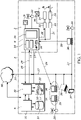
- FIG. 1 shows a schematic basic depiction of a mechatronic system 2.
- machine control data 1 are obtained, including, in exemplary fashion in FIG. 1 , a speed 1 (interchangeable with machine control data or machine control datum below).
- the machine control data 1 are communicated in the mechatronic system 2 in a network 3 having multiple network users 4, 6.
- the control data 1 are sent in the network 3 by an appropriately configured publisher by means of a data interchange standard that supports a publish/subscribe communication model.
- the data sent are received by a network user 6, 4 via the network 3 by means of the data interchange standard.
- the publisher performs the transmission in the form of network messages.
- the network messages sent are each intended for subscribers selectable as required that are decoupled from the publisher.
- a subscriber selectively obtains a network message with its control data 1 to be procured, in each case preferably under event control, or selects said network message; additionally or alternatively, the relevant subscriber can also selectively take the control data 1 to be procured from a received/analyzed network message.
- the network messages may be transmitted via a controller area network (CAN) protocol or any other communication method.
- CAN controller area network
- a machine controller 4 of the mechatronic system 2 is incorporated into the network 3 as a network user, specifically firstly via a field bus 21 that connects the machine controller 4 to industrial automation components; secondly via an asynchronous network segment 27 that connects the machine controller 4 to other IT components, such as for example PCs.
- the machine controller 4 can be configured indiscriminately as a subscriber and/or as a publisher. If it is configured as a publisher, then it provides the control data 1 with a message identifier 7, codes or decodes the control data by means of the data interchange standard to produce a network message and sends the network message via the network 3.
- the machine controller 4 If the machine controller 4 is configured as a subscriber, it receives a network message intended for this subscriber (this then being the machine controller 4) by means of the message identifier 7 via the network 3 and decodes the network message by means of the data interchange standard to produce usable control data 1.
- the mechatronic system 2 is designed to be communicative substantially with the industrial automation components by means of the field bus 21.
- the machine controller 4 has an integrated PLC 14 and a likewise integrated CNC 15.
- the visualization of machine control data 1 takes place via the display 16, which is likewise integrated in the machine controller 4.
- the machine controller 4 has a port for a USB stick 17 for interchanging control data within particular parties that are not incorporated in the network 3.
- there is a hard disk/SSD 18 that acts as an internal data memory of the machine controller and on which control data 1 are also stored, buffered and interchanged between the individual modules.
- the field bus 21 connects the machine controller 4 to two drive controllers 22, 23.
- the electric motor 25 is activated by the drive controller 23.
- the drive controller 22 actuates a servomotor 24.
- a tachometer 26 is used to return the instantaneous speed 1 (or other data used for actuating and/or monitoring the servo motor 24) to the drive controller 22.
- the speed 1 is likewise transmitted via the field bus 21 to the machine controller 4, where it is processed and used for communication in accordance with the disclosure.
- a clock provided for a system time 19 of the machine controller 4.
- the control data 1 can be provided with a system time-in particular a system time synchronized throughout the system-for example in the form of a timestamp by means of the clock 19.
- the network 3 may also use the asynchronous network segment 27 to set up a communication connection between the mechatronic system 2 or components of the mechatronic system 2 and a network infrastructure that is based on an asynchronous (also non-realtime-compatible) network protocol.
- a synchronous network segment may also be utilized.
- the asynchronous network segment 27 has been used to incorporate an industrial PC 6.
- the industrial PC 6 likewise has an internal hard disk/SSD 18 and a port for a USB stick 17 (see above); in addition, a CD/DVD drive 33 is shown in exemplary fashion, this likewise being able to be used to load or forward communicated control data 1 in accordance with the disclosure.
- OPC-UA-compliant application entity 30 an OPC-UA-compliant application entity 30 and a PC application 31 for control data 1 (e.g. a control or simulation tool) are shown in exemplary fashion.
- the data interchange standard is OPC-UA.
- the OPC-UA-compliant application entity 30 of the industrial PC 6 is used to make available the OPC-UAstandard-compliant functionalities, in particular the communication via OPC-UA, on a commercially available industrial PC 6.
- the control data 1 received or sent or decoded or encoded by means of the OPC-UA-compliant application 30 are then bidirectionally interchanged with practically any PC application 31, selectable as required, for control data 1, so that the communication of the control data in accordance with the disclosure is realized.
- control data 1 become interchangeable with further network users 34, 35, 36, 37, 38 via an OPC-UA-compliant interface.
- each network user 4, 6, 34, 35, 36, 37, 38 also has an OPC-UA-compliant interface and/or application.
- the asynchronous network segment 27 has additionally also been used to incorporate into the infrastructure:
- Office PCs 34 that act in cooperation as an EDGE computing system 35, in which for example analysis tasks or computing tasks relating to the mechatronic system 2 are relocated.
- One part of the asynchronous network segment 27 is also a wireless transmitter 20, which is likewise used to transmit control data 1, inter alia.
- a network connection to a cloud 66 accessible via the internet for example for storing control data 1 with global availability, for example for preventive maintenance or analysis of mechatronic systems 2).
- the machine controller 4 is configured firstly as a publisher and simultaneously as a subscriber. To this end, the machine controller 4 is incorporated in the mechatronic system 2 as a network user and can communicate control data 1 that are on the machine controller 4 in the whole network 3.
- the drive controller 22 has a drive-integrated machine controller (not shown here) or a drive-integrated PLC.
- the publisher paths 28 are physical and/or virtual paths that use the communication infrastructure of the network 3 and are physically realized by means of Ethernet and/or by means of wireless transmitter 20 and/or by means of the field bus 21, for example (this also applies mutatis mutandis to the subscriber paths 29, in this regard see later on).
- the machine controller 4 when configured as a publisher, it provides the control data with a message identifier 7, encodes said control data as a network message by utilizing a communication protocol and sends the network message via the network 3.
- network users 6, 35 configured as subscribers in the asynchronous network segment 27 are present that receive the control data 1 published by the machine controller 4 in accordance with the disclosure.
- the control data 1 coming from the mechatronic system 2 are made available on the office PC 6 and also in the EDGE computing system 35.
- the industrial PC 6 has an OPC-UA-compliant application entity 30, which is an application running on the industrial PC and communicates bidirectionally with a target PC application 31 for control data 1 and transmits the control data 1 interchanged in OPC-UA-compliant fashion.
- an OPC-UA-compliant application entity 30 of this kind or an OPC-UA-compliant application may be present on each of the network users 4, 6, 34, 35, 36, 37, 38.
- a drive controller 22 configured as a subscriber is present that uses the publisher path 28 (as seen from the point of view of the machine controller 4) to receive the control data 1 from the machine controller 4; this can take place physically via the field bus 21, so that the communication of the control data 1 can also take place in real time.
- the machine controller 4 is configured as a subscriber (specifically, as above in the case of the configuration as a publisher too, in each case the control-integrated PLC 14). In this case, it uses the subscriber path 29 (from the machine controller point of view) to receive control data from the industrial PC 6.
- FIG. 2 shows a schematic basic depiction of a mechatronic system 2 having industrial automation components that use a field bus 44 to communicate among one another and with other network users or automation components.
- the field bus 44 may be any type of communication bus, such as or similar to a CAN bus.
- a field bus ring topology 44 may connect multiple machine controllers 4, 39, 40, 41, 42 (collectively referred to as 4+ below for the sake of simplicity) so as to communicate among one another in real time; this can be for example a Sercos field bus, an EtherCAT field bus, a Profinet field bus or a TSN based field bus or a realtime-compatible TSN network.
- the field bus ring topology 44 is an oppositely directed double ring in order to provide, for example, a redundancy suitable for safety applications.
- a star topology (or any other topology) can be realized for TSN by using a TSNcompatible switch.
- the machine controllers 4, 39 may have industrial automation components connected to them.
- the machine controller 4 can act as a master.
- the machine controller 40 has a drive controller 43, having an integrated machine controller (e.g. PLC), connected to it, via a realtime communication medium, such as a field bus 21. Otherwise, another two drive controllers 22, each influencing a servomotor 24 or an electric motor 25, are connected.
- PLC integrated machine controller
- the machine controller 41 merely has a drive controller 43, having an integrated machine controller, connected to it via the field bus 21, said drive controller influencing a servomotor 24 having a tachometer 26; the tachometer 26 is used to return the speed 1 to the drive controller 43 in each case.
- the machine controller 42 has a drive controller 22, having connected servomotor 24/tachometer 26 combination, and a drive controller 43, having an integrated machine controller and an electric motor 25 influenced thereby, connected to it.
- publish/subscribe communication paths 45 which can be realized virtually or physically, may be shown in accordance with the disclosure. By way of example, they can be physically implemented by means of the field bus ring topology 44, or by utilizing further communication connections, which are not shown here.
- the machine controller 4 is configured as a publisher and sends control data procured from the machine controller 41, which in this regard is configured as a subscriber, via the communication path 45. Simultaneously, the machine controller 4 is configured as a subscriber for control data 1 procured from the machine controller 41, which in this regard is configured as a publisher. At the same time, the machine controller 4-configured as a subscriber-procures published control data from the machine controller 42 as a publisher.
- Control data can also be communicated by drives 22, 43 in accordance with the disclosure.
- the machine controller 39 is configured as a subscriber for control data 1 published by the drive controller 43, with an integrated machine controller, that is connected to the machine controller 41 via the field bus 21 as a publisher.
- the drive controller 43 connected to the machine controller 42 also procures control data 1 from this drive controller 43 connected to the machine controller 41.
- the drive controller 43 connected to the machine controller 40 is configured as a publisher and publishes control data that (inter alia) are received by the machine controller 41, which in this respect is configured as a subscriber, via the communication path 45. Both the direct communication via the field bus ring topology 44 and the communication via the publish/subscribe communication paths 45 shown may take place in real time.
- FIG. 3 is an example of an in-vehicle network that includes such a honeypot system.
- a vehicle system 301 may include a first CAN bus network 303 and a second CAN bus network 305.
- One of the CAN bus networks may include lower criticality systems and ECU's connected on that network, such as a telematics system, navigation system, multimedia system, etc.
- the other CAN bus network may include higher criticality systems. Such higher criticality systems may be utilized to operate the vehicle, such as the braking system (e.g., any system related ECU), the electronic throttle control, engine control unit, etc.
- the gateway 307 that operates to communicate between the different networks in the vehicle.
- honeypot 309 utilized as a security mechanism.
- the honeypot 309 may act as a security mechanism by being a diversion to thwart attackers.
- the honey pot 309 may thwart attackers by emulating vehicle data.
- the honeypot 309 may not actually communication with operational ECUs that control vehicle functionality.
- automotive honeypots 309 may attempt to emulate the entire car, in particular the device that is connected to a remote network.
- the honeypot 309 may thus emulate communication with various ECUs, however, the honeypot 309 may not interfere with benign communication (e.g., not an attack or vulnerability) between the various ECUs on the bus that are communicating with one another.
- An example is the internet connectivity of an infotainment system, or a vehicle-to-vehicle (V2V) or vehicle-to-everything (V2X) controller in a vehicle with high autonomy or fully autonomous driving.
- V2V vehicle-to-vehicle
- V2X vehicle-to-everything
- the vehicle may utilize a fake gateway controller to act as a honeypot.
- a typical gateway controller may be an interesting target for an attacker because it may connect multiple busses of the car with each other, similar to a router. However, the busses may have different levels of safety criticality.
- One security practice may be to not connect any safety critical ECU to networks that have controllers in connection with outside networks.
- the infotainment system on CAN A is not being directly connected to a safety critical ECU like the drivetrain or brakes on CAN B.
- any ECU 311 can be used as a honeypot 309, thus the honeypot 309 may be configured to emulate an ECU.
- the honeypot 309 may be configured to run fake commands, however, the honeypot 309 is not in communication with active vehicle components (e.g., like the Engine ECU), but may be running commands to emulate such data communication that would normally happen between the component the honeypot is mimicking and various vehicle components.
- the honeypot is not limited to simply emulate just a gateway between various vehicle buses, it may implement any vehicle component.
- the ECU 311 may be powertrain ECU on a safety critical bus, or a combination of multiple honeypot ECUs.
- the honeypot could be deployed on every car in the fleet, or just randomly selected cars.
- the honeypot 309 could also include vulnerable code or software that is loaded onto memory of the honeypot 309, or a vulnerable ECU in communication with the honeypot 309, or any other ECU. Thus, such vulnerabilities may bait an attacker. Usually an attacker requires multiple vulnerabilities to get a level of control that they need to deploy a full attack, but such vulnerable code could eliminate that.
- the honeypot may have some potential attack surfaces an attacker could use.
- One may be that it is at an end of arbitrary CAN messages to determine which module responds to which ID and message. This may require brute force and reverse engineering, which may be detected by that honeypot, and even further encouraged by fake-responding to CAN messages.
- an attacker may take over an infotainment system. From that point, the attacker may determine a way to flash a new firmware on the CAN controller part (e.g., software or hardware that operates with the CAN controller) of the infotainment system. From there, the attacker may send arbitrary CAN messages to the CAN bus to see which controller reacts to which CAN ID messages.
- a honeypot 309 may be utilized to identify such activity, such as the arbitrary CAN messages, which CAN bus the messages are sent to, and which controller would react to which CAN ID messages.
- the honeypot 309 may also be utilized as a sink for multiple CAN IDs and messages, and actively respond to them in order to attract an attacker to the honeypot 309.
- the honeypot 309 may also be utilized to monitor secure flashing.
- Unified Diagnostic Services For secure flashing (and other diagnostics) of controllers that are connected to a CAN bus within a vehicle, Unified Diagnostic Services (UDS).
- UDS Unified Diagnostic Services
- a security feature of UDS may be a seed / key algorithm, which may often require some kind of brute forcing / data collection to break. Such a seed may be simulated by the honeypot, to lure an attacker into attacking a certain device. Then, the vehicle system may collect information about the attacker and its capabilities. Such information may include where the attack was started, capabilities of the attacker, and other similar information.
- the open JTAG (or SPI, i2C) interfaces may be utilized to directly flash a microcontroller.
- the honeypot may utilize a fake JTAG interface and could be presented on an attacker (physically visible on the microcontroller) to trick an attacker into attacking the honeypot.
- the system could use the honeypot to instead of just faking a JTAG interface, fake a complete microcontroller with a JTAG (or other similar) interface.
- the system may have the honeypot record (e.g., store) what a real gateway did in the past and replay those actions and commands.
- the honeypot and system may have information to replicate past actions of a real gateway, including the types of data communication and to what ECUs or vehicle components that data goes to.
- the system or the honeypot may utilize a recording of what a real gateway has done in terms of operations in the past.
- the system may record gateway operations of an actual honeypot (not a gateway) and have the honeypot mimic operation.
- the replay may utilize actually known responses to seen states and transitions in an effort to mimic the emulation of the honeypot.
- the system and honeypot may also simulate a gateway by a rule-based system. For example, the system and honeypot may determine if a certain message (e.g., message x) comes from CAN bus A, then translates to a different message (e.g., message y) to CAN bus B, it may wait a threshold time (e.g., two seconds), then send a reply from CAN bus B to CAN bus A.
- a threshold time e.g., two seconds
- FIG. 3 While the operation of FIG. 3 is shown with respect to a vehicle, any type of system may be utilized. For example, similar techniques may also be used in the areas of Internet-of-Things (IOT) or Industry 4.0, where an attack is taken as a risk, but honeypots are deployed deeper inside real systems.
- IOT Internet-of-Things
- Industry 4.0 Industry 4.0
- FIG. 4 is an example flow chart of a process and method utilizing a honeypot to counteract an attack.
- a processor or controller that is a part of the honeypot or in communication with the honeypot may receive data from one or more remote devices or ECUs in communication with a remote device.
- the data may be any type of data, such as a communication command, notification, or any other data.
- the system may monitor such data from the remote device.
- the data may be analyzed in order to determine if the data needs to be communicated to another recipient (e.g., another ECU) or executed.
- the system may determine if such data from the remote device is from a potential attacker.
- the system may analyze the data for threatening code or commands that may execute malware, viruses, security threats, etc. If the system determines that the data is not from an attacker, it may continue to simply monitor the data.
- the system may have code or programs utilized to monitor such data to determine if the activity is from an attacker.
- the system may then execute a counter operation based on the determination.
- the potential counter action may be complete silence, and thus the system may simply not operate any countermeasure and utilize the honeypot as a diversion.
- the honeypot may be utilized to log the intrusion.
- the honeypot may record data related to the intrusion, such as an IP address, MAC address, device name, commands, messages, identifiers, or other data related to the intrusion.
- data related to the intrusion such as an IP address, MAC address, device name, commands, messages, identifiers, or other data related to the intrusion.
- Such information may be analyzed locally or be sent to a control center.
- the attack can be analyzed either locally or remotely (e.g., at the control center) to determine future security enhancements to other security mechanisms and ECUs, such as more robust code, to prevent such attacks from happening in the future.
- the countermeasures may be one of the following above or any of the countermeasures above in a combination.
- the processes, methods, or algorithms disclosed herein can be deliverable to/implemented by a processing device, controller, or computer, which can include any existing programmable electronic control unit or dedicated electronic control unit.
- the processes, methods, or algorithms can be stored as data and instructions executable by a controller or computer in many forms including, but not limited to, information permanently stored on non-writable storage media such as ROM devices and information alterably stored on writeable storage media such as floppy disks, magnetic tapes, CDs, RAM devices, and other magnetic and optical media.
- the processes, methods, or algorithms can also be implemented in a software executable object.
- the processes, methods, or algorithms can be embodied in whole or in part using suitable hardware components, such as Application Specific Integrated Circuits (ASICs), Field-Programmable Gate Arrays (FPGAs), state machines, controllers or other hardware components or devices, or a combination of hardware, software and firmware components.
- suitable hardware components such as Application Specific Integrated Circuits (ASICs), Field-Programmable Gate Arrays (FPGAs), state machines, controllers or other hardware components or devices, or a combination of hardware, software and firmware components.
Landscapes
- Engineering & Computer Science (AREA)
- Computer Security & Cryptography (AREA)
- Computer Networks & Wireless Communication (AREA)
- Signal Processing (AREA)
- Computing Systems (AREA)
- Computer Hardware Design (AREA)
- General Engineering & Computer Science (AREA)
- Health & Medical Sciences (AREA)
- General Health & Medical Sciences (AREA)
- Medical Informatics (AREA)
- Small-Scale Networks (AREA)
Applications Claiming Priority (1)
| Application Number | Priority Date | Filing Date | Title |
|---|---|---|---|
| US17/160,946 US20220239694A1 (en) | 2021-01-28 | 2021-01-28 | System and method for detection and deflection of attacks on in-vehicle controllers and networks |
Publications (2)
| Publication Number | Publication Date |
|---|---|
| EP4057571A1 true EP4057571A1 (fr) | 2022-09-14 |
| EP4057571B1 EP4057571B1 (fr) | 2025-04-30 |
Family
ID=80119437
Family Applications (1)
| Application Number | Title | Priority Date | Filing Date |
|---|---|---|---|
| EP22153725.1A Active EP4057571B1 (fr) | 2021-01-28 | 2022-01-27 | Système et procédé de détection et de déviation d'attaques sur des organes de commande et des réseaux embarqués |
Country Status (4)
| Country | Link |
|---|---|
| US (1) | US20220239694A1 (fr) |
| EP (1) | EP4057571B1 (fr) |
| KR (1) | KR20220109352A (fr) |
| CN (1) | CN114826643B (fr) |
Families Citing this family (2)
| Publication number | Priority date | Publication date | Assignee | Title |
|---|---|---|---|---|
| JP7760989B2 (ja) * | 2022-11-07 | 2025-10-28 | トヨタ自動車株式会社 | 攻撃検知システム |
| JP2025062920A (ja) * | 2023-10-03 | 2025-04-15 | トヨタ自動車株式会社 | 通信システム、制御装置、及び、通信方法 |
Citations (1)
| Publication number | Priority date | Publication date | Assignee | Title |
|---|---|---|---|---|
| WO2020120160A1 (fr) * | 2018-12-10 | 2020-06-18 | Daimler Ag | Procédé de détection d'intrusion dans un bus de terrain distribué d'un réseau et système associé |
Family Cites Families (15)
| Publication number | Priority date | Publication date | Assignee | Title |
|---|---|---|---|---|
| US8087083B1 (en) * | 2002-01-04 | 2011-12-27 | Verizon Laboratories Inc. | Systems and methods for detecting a network sniffer |
| US9173100B2 (en) * | 2011-11-16 | 2015-10-27 | Autoconnect Holdings Llc | On board vehicle network security |
| US9503324B2 (en) * | 2013-11-05 | 2016-11-22 | Harris Corporation | Systems and methods for enterprise mission management of a computer network |
| US10824720B2 (en) * | 2014-03-28 | 2020-11-03 | Tower-Sec Ltd. | Security system and methods for identification of in-vehicle attack originator |
| CA3004893A1 (fr) * | 2015-11-12 | 2017-05-18 | Mercury Systems, Inc. | Filtre a cadres de bus de diffusion |
| EP3566164B1 (fr) * | 2017-01-03 | 2024-04-10 | Karamba Security Ltd. | Sécurité de contrôleur reposant sur un mode et prévention contre un logiciel malveillant |
| EP3699794A1 (fr) * | 2017-08-10 | 2020-08-26 | Argus Cyber Security Ltd. | Système et procédé de détection d'exploitation d'un composant connecté à un réseau de communication embarqué |
| US11030310B2 (en) * | 2017-08-17 | 2021-06-08 | Red Bend Ltd. | Systems and methods for disabling a malicious ECU in a controller area network (CAN) bus |
| JP7045286B2 (ja) * | 2018-01-22 | 2022-03-31 | パナソニック インテレクチュアル プロパティ コーポレーション オブ アメリカ | データ解析装置、データ解析方法及びプログラム |
| JP6950605B2 (ja) * | 2018-03-27 | 2021-10-13 | トヨタ自動車株式会社 | 車両用通信システム |
| RU2706887C2 (ru) * | 2018-03-30 | 2019-11-21 | Акционерное общество "Лаборатория Касперского" | Система и способ блокирования компьютерной атаки на транспортное средство |
| WO2020068826A1 (fr) * | 2018-09-24 | 2020-04-02 | Karamba Security Ltd. | Système de sécurité de dispositif de commande électronique |
| US11876833B2 (en) * | 2019-08-15 | 2024-01-16 | Uchicago Argonne, Llc | Software defined networking moving target defense honeypot |
| US11509690B2 (en) * | 2019-11-21 | 2022-11-22 | Arbor Networks, Inc. | Management of botnet attacks to a computer network |
| US12058148B2 (en) * | 2020-05-01 | 2024-08-06 | Amazon Technologies, Inc. | Distributed threat sensor analysis and correlation |
-
2021
- 2021-01-28 US US17/160,946 patent/US20220239694A1/en not_active Abandoned
-
2022
- 2022-01-27 EP EP22153725.1A patent/EP4057571B1/fr active Active
- 2022-01-28 CN CN202210107406.4A patent/CN114826643B/zh active Active
- 2022-01-28 KR KR1020220013330A patent/KR20220109352A/ko active Pending
Patent Citations (1)
| Publication number | Priority date | Publication date | Assignee | Title |
|---|---|---|---|---|
| WO2020120160A1 (fr) * | 2018-12-10 | 2020-06-18 | Daimler Ag | Procédé de détection d'intrusion dans un bus de terrain distribué d'un réseau et système associé |
Non-Patent Citations (1)
| Title |
|---|
| VERENDEL V ET AL: "An Approach to using Honeypots in In-Vehicle Networks", VEHICULAR TECHNOLOGY CONFERENCE, 2008. VTC 2008-FALL. IEEE 68TH, IEEE, PISCATAWAY, NJ, USA, 21 September 2008 (2008-09-21), pages 1 - 5, XP031352443, ISBN: 978-1-4244-1721-6 * |
Also Published As
| Publication number | Publication date |
|---|---|
| KR20220109352A (ko) | 2022-08-04 |
| EP4057571B1 (fr) | 2025-04-30 |
| CN114826643B (zh) | 2026-03-31 |
| US20220239694A1 (en) | 2022-07-28 |
| CN114826643A (zh) | 2022-07-29 |
Similar Documents
| Publication | Publication Date | Title |
|---|---|---|
| US11063970B2 (en) | Attack detection method, attack detection device and bus system for a motor vehicle | |
| US10798117B2 (en) | Security processing method and server | |
| JP7641900B2 (ja) | 侵入経路分析装置および侵入経路分析方法 | |
| US11165851B2 (en) | System and method for providing security to a communication network | |
| Larson et al. | An approach to specification-based attack detection for in-vehicle networks | |
| Fröschle et al. | Analyzing the capabilities of the CAN attacker | |
| US10798114B2 (en) | System and method for consistency based anomaly detection in an in-vehicle communication network | |
| EP3528163A1 (fr) | Protection cryptique de véhicule | |
| US20160381068A1 (en) | System and method for time based anomaly detection in an in-vehicle communication network | |
| EP4057571B1 (fr) | Système et procédé de détection et de déviation d'attaques sur des organes de commande et des réseaux embarqués | |
| JP2019013007A (ja) | グローバル自動車安全システム | |
| Jadhav et al. | A survey on security in automotive networks | |
| US10574671B2 (en) | Method for monitoring security in an automation network, and automation network | |
| JP7784617B2 (ja) | 機器診断装置、遠隔機器監視方法、遠隔機器監視システム及び機器診断プログラム | |
| Wu et al. | IDH-CAN: A hardware-based ID hopping CAN mechanism with enhanced security for automotive real-time applications | |
| Werquin et al. | Automated fuzzing of automotive control units | |
| CN113169966B (zh) | 用于监控数据传输系统的方法、数据传输系统和机动车 | |
| Campo et al. | Real-time network defense of SAE J1939 address claim attacks | |
| Toghuj et al. | Automotive Ethernet architecture and security: challenges and technologies. | |
| US20180316700A1 (en) | Data security inspection mechanism for serial networks | |
| CN117544495A (zh) | 配置车载网关的方法、装置、设备及存储介质 | |
| Yung et al. | Security issues and mitigation in ethernet powerlink | |
| Werquin | Automated reverse engineering and fuzzing of the can bus | |
| Lambert et al. | Design and development of xivenet: A hybrid can research testbed | |
| Wang et al. | Intelligent Connected Vehicle Security: Threats, Attacks and Defenses. |
Legal Events
| Date | Code | Title | Description |
|---|---|---|---|
| PUAI | Public reference made under article 153(3) epc to a published international application that has entered the european phase |
Free format text: ORIGINAL CODE: 0009012 |
|
| STAA | Information on the status of an ep patent application or granted ep patent |
Free format text: STATUS: THE APPLICATION HAS BEEN PUBLISHED |
|
| AK | Designated contracting states |
Kind code of ref document: A1 Designated state(s): AL AT BE BG CH CY CZ DE DK EE ES FI FR GB GR HR HU IE IS IT LI LT LU LV MC MK MT NL NO PL PT RO RS SE SI SK SM TR |
|
| STAA | Information on the status of an ep patent application or granted ep patent |
Free format text: STATUS: REQUEST FOR EXAMINATION WAS MADE |
|
| 17P | Request for examination filed |
Effective date: 20230221 |
|
| RBV | Designated contracting states (corrected) |
Designated state(s): AL AT BE BG CH CY CZ DE DK EE ES FI FR GB GR HR HU IE IS IT LI LT LU LV MC MK MT NL NO PL PT RO RS SE SI SK SM TR |
|
| GRAP | Despatch of communication of intention to grant a patent |
Free format text: ORIGINAL CODE: EPIDOSNIGR1 |
|
| STAA | Information on the status of an ep patent application or granted ep patent |
Free format text: STATUS: GRANT OF PATENT IS INTENDED |
|
| RIC1 | Information provided on ipc code assigned before grant |
Ipc: H04L 12/40 20060101ALN20241118BHEP Ipc: H04L 67/12 20220101ALN20241118BHEP Ipc: H04L 9/40 20220101AFI20241118BHEP |
|
| INTG | Intention to grant announced |
Effective date: 20241129 |
|
| GRAS | Grant fee paid |
Free format text: ORIGINAL CODE: EPIDOSNIGR3 |
|
| GRAA | (expected) grant |
Free format text: ORIGINAL CODE: 0009210 |
|
| STAA | Information on the status of an ep patent application or granted ep patent |
Free format text: STATUS: THE PATENT HAS BEEN GRANTED |
|
| AK | Designated contracting states |
Kind code of ref document: B1 Designated state(s): AL AT BE BG CH CY CZ DE DK EE ES FI FR GB GR HR HU IE IS IT LI LT LU LV MC MK MT NL NO PL PT RO RS SE SI SK SM TR |
|
| REG | Reference to a national code |
Ref country code: CH Ref legal event code: EP Ref country code: GB Ref legal event code: FG4D |
|
| REG | Reference to a national code |
Ref country code: IE Ref legal event code: FG4D |
|
| REG | Reference to a national code |
Ref country code: DE Ref legal event code: R096 Ref document number: 602022013730 Country of ref document: DE |
|
| REG | Reference to a national code |
Ref country code: NL Ref legal event code: MP Effective date: 20250430 |
|
| REG | Reference to a national code |
Ref country code: AT Ref legal event code: MK05 Ref document number: 1791116 Country of ref document: AT Kind code of ref document: T Effective date: 20250430 |
|
| PG25 | Lapsed in a contracting state [announced via postgrant information from national office to epo] |
Ref country code: FI Free format text: LAPSE BECAUSE OF FAILURE TO SUBMIT A TRANSLATION OF THE DESCRIPTION OR TO PAY THE FEE WITHIN THE PRESCRIBED TIME-LIMIT Effective date: 20250430 Ref country code: PT Free format text: LAPSE BECAUSE OF FAILURE TO SUBMIT A TRANSLATION OF THE DESCRIPTION OR TO PAY THE FEE WITHIN THE PRESCRIBED TIME-LIMIT Effective date: 20250901 Ref country code: ES Free format text: LAPSE BECAUSE OF FAILURE TO SUBMIT A TRANSLATION OF THE DESCRIPTION OR TO PAY THE FEE WITHIN THE PRESCRIBED TIME-LIMIT Effective date: 20250430 |
|
| REG | Reference to a national code |
Ref country code: LT Ref legal event code: MG9D |
|
| PG25 | Lapsed in a contracting state [announced via postgrant information from national office to epo] |
Ref country code: NO Free format text: LAPSE BECAUSE OF FAILURE TO SUBMIT A TRANSLATION OF THE DESCRIPTION OR TO PAY THE FEE WITHIN THE PRESCRIBED TIME-LIMIT Effective date: 20250730 Ref country code: GR Free format text: LAPSE BECAUSE OF FAILURE TO SUBMIT A TRANSLATION OF THE DESCRIPTION OR TO PAY THE FEE WITHIN THE PRESCRIBED TIME-LIMIT Effective date: 20250731 |
|
| PG25 | Lapsed in a contracting state [announced via postgrant information from national office to epo] |
Ref country code: NL Free format text: LAPSE BECAUSE OF FAILURE TO SUBMIT A TRANSLATION OF THE DESCRIPTION OR TO PAY THE FEE WITHIN THE PRESCRIBED TIME-LIMIT Effective date: 20250430 Ref country code: PL Free format text: LAPSE BECAUSE OF FAILURE TO SUBMIT A TRANSLATION OF THE DESCRIPTION OR TO PAY THE FEE WITHIN THE PRESCRIBED TIME-LIMIT Effective date: 20250430 |
|
| PG25 | Lapsed in a contracting state [announced via postgrant information from national office to epo] |
Ref country code: BG Free format text: LAPSE BECAUSE OF FAILURE TO SUBMIT A TRANSLATION OF THE DESCRIPTION OR TO PAY THE FEE WITHIN THE PRESCRIBED TIME-LIMIT Effective date: 20250430 |
|
| PG25 | Lapsed in a contracting state [announced via postgrant information from national office to epo] |
Ref country code: HR Free format text: LAPSE BECAUSE OF FAILURE TO SUBMIT A TRANSLATION OF THE DESCRIPTION OR TO PAY THE FEE WITHIN THE PRESCRIBED TIME-LIMIT Effective date: 20250430 |
|
| PG25 | Lapsed in a contracting state [announced via postgrant information from national office to epo] |
Ref country code: AT Free format text: LAPSE BECAUSE OF FAILURE TO SUBMIT A TRANSLATION OF THE DESCRIPTION OR TO PAY THE FEE WITHIN THE PRESCRIBED TIME-LIMIT Effective date: 20250430 |
|
| PG25 | Lapsed in a contracting state [announced via postgrant information from national office to epo] |
Ref country code: RS Free format text: LAPSE BECAUSE OF FAILURE TO SUBMIT A TRANSLATION OF THE DESCRIPTION OR TO PAY THE FEE WITHIN THE PRESCRIBED TIME-LIMIT Effective date: 20250731 |
|
| PG25 | Lapsed in a contracting state [announced via postgrant information from national office to epo] |
Ref country code: IS Free format text: LAPSE BECAUSE OF FAILURE TO SUBMIT A TRANSLATION OF THE DESCRIPTION OR TO PAY THE FEE WITHIN THE PRESCRIBED TIME-LIMIT Effective date: 20250830 |
|
| PG25 | Lapsed in a contracting state [announced via postgrant information from national office to epo] |
Ref country code: LV Free format text: LAPSE BECAUSE OF FAILURE TO SUBMIT A TRANSLATION OF THE DESCRIPTION OR TO PAY THE FEE WITHIN THE PRESCRIBED TIME-LIMIT Effective date: 20250430 |
|
| PG25 | Lapsed in a contracting state [announced via postgrant information from national office to epo] |
Ref country code: DK Free format text: LAPSE BECAUSE OF FAILURE TO SUBMIT A TRANSLATION OF THE DESCRIPTION OR TO PAY THE FEE WITHIN THE PRESCRIBED TIME-LIMIT Effective date: 20250430 Ref country code: SM Free format text: LAPSE BECAUSE OF FAILURE TO SUBMIT A TRANSLATION OF THE DESCRIPTION OR TO PAY THE FEE WITHIN THE PRESCRIBED TIME-LIMIT Effective date: 20250430 |
|
| PG25 | Lapsed in a contracting state [announced via postgrant information from national office to epo] |
Ref country code: CZ Free format text: LAPSE BECAUSE OF FAILURE TO SUBMIT A TRANSLATION OF THE DESCRIPTION OR TO PAY THE FEE WITHIN THE PRESCRIBED TIME-LIMIT Effective date: 20250430 |
|
| PG25 | Lapsed in a contracting state [announced via postgrant information from national office to epo] |
Ref country code: EE Free format text: LAPSE BECAUSE OF FAILURE TO SUBMIT A TRANSLATION OF THE DESCRIPTION OR TO PAY THE FEE WITHIN THE PRESCRIBED TIME-LIMIT Effective date: 20250430 |
|
| PG25 | Lapsed in a contracting state [announced via postgrant information from national office to epo] |
Ref country code: SK Free format text: LAPSE BECAUSE OF FAILURE TO SUBMIT A TRANSLATION OF THE DESCRIPTION OR TO PAY THE FEE WITHIN THE PRESCRIBED TIME-LIMIT Effective date: 20250430 |
|
| PG25 | Lapsed in a contracting state [announced via postgrant information from national office to epo] |
Ref country code: IT Free format text: LAPSE BECAUSE OF FAILURE TO SUBMIT A TRANSLATION OF THE DESCRIPTION OR TO PAY THE FEE WITHIN THE PRESCRIBED TIME-LIMIT Effective date: 20250430 |
|
| REG | Reference to a national code |
Ref country code: DE Ref legal event code: R097 Ref document number: 602022013730 Country of ref document: DE |
|
| PLBE | No opposition filed within time limit |
Free format text: ORIGINAL CODE: 0009261 |
|
| STAA | Information on the status of an ep patent application or granted ep patent |
Free format text: STATUS: NO OPPOSITION FILED WITHIN TIME LIMIT |
|
| REG | Reference to a national code |
Ref country code: CH Ref legal event code: L10 Free format text: ST27 STATUS EVENT CODE: U-0-0-L10-L00 (AS PROVIDED BY THE NATIONAL OFFICE) Effective date: 20260311 |
|
| 26N | No opposition filed |
Effective date: 20260202 |
|
| PGFP | Annual fee paid to national office [announced via postgrant information from national office to epo] |
Ref country code: GB Payment date: 20260122 Year of fee payment: 5 |
|
| PGFP | Annual fee paid to national office [announced via postgrant information from national office to epo] |
Ref country code: DE Payment date: 20260319 Year of fee payment: 5 |
|
| PGFP | Annual fee paid to national office [announced via postgrant information from national office to epo] |
Ref country code: FR Payment date: 20260128 Year of fee payment: 5 |