EP4057721B1 - Methods and terminal for paging a multi-sim terminal - Google Patents
Methods and terminal for paging a multi-sim terminal Download PDFInfo
- Publication number
- EP4057721B1 EP4057721B1 EP20885842.3A EP20885842A EP4057721B1 EP 4057721 B1 EP4057721 B1 EP 4057721B1 EP 20885842 A EP20885842 A EP 20885842A EP 4057721 B1 EP4057721 B1 EP 4057721B1
- Authority
- EP
- European Patent Office
- Prior art keywords
- network
- terminal
- paging
- data
- information
- Prior art date
- Legal status (The legal status is an assumption and is not a legal conclusion. Google has not performed a legal analysis and makes no representation as to the accuracy of the status listed.)
- Active
Links
Images








Classifications
-
- H—ELECTRICITY
- H04—ELECTRIC COMMUNICATION TECHNIQUE
- H04W—WIRELESS COMMUNICATION NETWORKS
- H04W60/00—Affiliation to network, e.g. registration; Terminating affiliation with the network, e.g. de-registration
-
- H—ELECTRICITY
- H04—ELECTRIC COMMUNICATION TECHNIQUE
- H04W—WIRELESS COMMUNICATION NETWORKS
- H04W48/00—Access restriction; Network selection; Access point selection
- H04W48/18—Selecting a network or a communication service
-
- H—ELECTRICITY
- H04—ELECTRIC COMMUNICATION TECHNIQUE
- H04W—WIRELESS COMMUNICATION NETWORKS
- H04W60/00—Affiliation to network, e.g. registration; Terminating affiliation with the network, e.g. de-registration
- H04W60/005—Multiple registrations, e.g. multihoming
-
- H—ELECTRICITY
- H04—ELECTRIC COMMUNICATION TECHNIQUE
- H04W—WIRELESS COMMUNICATION NETWORKS
- H04W68/00—User notification, e.g. alerting and paging, for incoming communication, change of service or the like
-
- H—ELECTRICITY
- H04—ELECTRIC COMMUNICATION TECHNIQUE
- H04W—WIRELESS COMMUNICATION NETWORKS
- H04W68/00—User notification, e.g. alerting and paging, for incoming communication, change of service or the like
- H04W68/005—Transmission of information for alerting of incoming communication
-
- H—ELECTRICITY
- H04—ELECTRIC COMMUNICATION TECHNIQUE
- H04W—WIRELESS COMMUNICATION NETWORKS
- H04W68/00—User notification, e.g. alerting and paging, for incoming communication, change of service or the like
- H04W68/02—Arrangements for increasing efficiency of notification or paging channel
-
- H—ELECTRICITY
- H04—ELECTRIC COMMUNICATION TECHNIQUE
- H04W—WIRELESS COMMUNICATION NETWORKS
- H04W76/00—Connection management
- H04W76/10—Connection setup
-
- H—ELECTRICITY
- H04—ELECTRIC COMMUNICATION TECHNIQUE
- H04W—WIRELESS COMMUNICATION NETWORKS
- H04W76/00—Connection management
- H04W76/20—Manipulation of established connections
- H04W76/27—Transitions between radio resource control [RRC] states
-
- H—ELECTRICITY
- H04—ELECTRIC COMMUNICATION TECHNIQUE
- H04W—WIRELESS COMMUNICATION NETWORKS
- H04W76/00—Connection management
- H04W76/30—Connection release
-
- H—ELECTRICITY
- H04—ELECTRIC COMMUNICATION TECHNIQUE
- H04W—WIRELESS COMMUNICATION NETWORKS
- H04W88/00—Devices specially adapted for wireless communication networks, e.g. terminals, base stations or access point devices
- H04W88/02—Terminal devices
- H04W88/06—Terminal devices adapted for operation in multiple networks or having at least two operational modes, e.g. multi-mode terminals
-
- H—ELECTRICITY
- H04—ELECTRIC COMMUNICATION TECHNIQUE
- H04W—WIRELESS COMMUNICATION NETWORKS
- H04W36/00—Hand-off or reselection arrangements
Definitions
- US 2014/126522 A1 proposes a method and apparatus enabling a mobile device to receive paging notifications from multiple networks.
- USIMs Universal Subscriber Identity Modules
- the present disclosure may provide a method and apparatus for operating a terminal in a wireless communication system.
- the present disclosure may provide a method and apparatus for a multi-SIM terminal to receive a paging message in a wireless communication system.
- the present disclosure may provide a method and apparatus for a multi-SIM terminal to transition to a network.
- a method of operating a terminal based on a plurality of networks in a wireless communication system defined in claim 1 is provided.
- a terminal operating in a wireless communication system defined in claim 9 is provided.
- a method of operating a network in a wireless communication system defined in claim 10 is provided.
- the paging-related information may indicate the data desiring to receive paging based on at least any one of a logical channel, a packet data unit (PDU) session, a network slice, a data network name (DNN), and IP multimedia subsystem (IMS) service information.
- PDU packet data unit
- DNN data network name
- IMS IP multimedia subsystem
- the paging-related information may further include identifier information for the information indicating the data desiring to receive paging.
- the terminal in case the terminal receives the paging message from the first network after the terminal transitions to the second network, the terminal releases the connection of the second network based on the paging message corresponding to the paging-related information of the first network, the terminal may transition from the second network to the first network.
- the terminal in case the terminal receives the paging message from the first network after the terminal transitions to the second network, if the paging message does not correspond to the paging-related information of the first network, the terminal may maintain connection with the second network.
- the terminal may transition to the first network.
- the terminal in case the terminal receives a paging message from the second network after having established a connection to the first network, if a priority of data corresponding to the paging message is higher than a preset priority, the terminal may transition from the first network to the second network.
- a connection to the first network may be maintained.
- the terminal may operate based on a plurality of subscriber identification modules (SIMs).
- SIMs subscriber identification modules
- the first network may correspond to a first SIM
- the second network may correspond to a second SIM
- a terminal may receive paging only for desired information based on paging condition information.
- the terminal when a terminal transitions to a network based on multi-SIM, the terminal may determine whether or not to transition to the network by setting a paging condition.
- the terminal when a terminal transitions to a network based on multi-SIM, the terminal may set various granularities of information desiring to receive paging.
- Effects obtained in the present disclosure are not limited to the above-mentioned effects, and other effects not mentioned above may be clearly derived and understood by those skilled in the art, to which a technical configuration of the present disclosure is applied, from the following description of embodiments of the present disclosure. That is, effects, which are not intended when implementing a configuration described in the present disclosure, may also be derived by those skilled in the art from the embodiments of the present disclosure.
- the embodiments of the present disclosure are described with focus on the relationship of data reception and transmission between a base station and a mobile station.
- the base station means a terminal node of a network that performs direct communication with the mobile station.
- a specific operation which is described to be performed by a base station, may be performed by an upper node of the base station in some cases.
- base station may be replaced by such terms as "fixed station”, “Node B”, “eNode B(eNB)”, “gNode B(gNB)”, “ng-eNB”, “advanced base station(ABS)", or "access point”.
- terminal may be replaced by such terms as “user equipment(UE)”, “mobile station(MS)”, “subscriber station(SS)”, “mobile subscriber station(MSS)”, “mobile terminal” or “advanced mobile station(AMS)”.
- UE user equipment
- MS mobile station
- SS subscriber station
- MSS mobile subscriber station
- AMS mobile terminal
- a transmission end refers to a fixed and/or mobile node that provides a data service or a voice service
- a reception end means a fixed and/or mobile node that receives a data service or a voice service.
- a mobile station may be a transmission end, and a base station may be a reception end.
- a mobile station may be a reception end, and a base station may be a transmission end.
- the embodiments of the present disclosure may be supported by standard documents disclosed in at least one of the following radio access systems: an IEEE 802 xx system, a 3rd generation partnership project (3GPP) system, a 3GPP long term evolution (LTE) system, a 3GPP 5th generation (5G) new radio (NR) system and a 3GPP2 system, and in particular, the embodiments of the present disclosure may be supported by the following documents: 3GPP TS (technical specification) 38.211, 3GPP TS 38.212, 3GPP TS 38.213, 3GPP TS 38.321, and 3GPP TS 38.331.
- 3GPP TS technical specification
- the embodiments of the present disclosure are applicable to another radio access system but is not limited to the above-described system. As an example, they are applicable to a system applied after a 3GPP 5G NR system and are not limited to a specific system.
- CDMA Code Division Multiple Access
- FDMA Frequency Division Multiple Access
- TDMA Time Division Multiple Access
- OFDMA Orthogonal Frequency Division Multiple Access
- SC-FDMA Single Carrier Frequency Division Multiple Access
- LTE may mean a technology after 3GPP TS 36.xxx Release 8.
- LTE-A the LTE technology after 3GPP TS 36.xxx Release 10
- LTE-A pro the LTE technology after 3GPP TS 36.xxx Release 13
- 3GPP NR may mean a technology after TS 38.xxx Release 15.
- 3GPP 6G may mean a technology after TS Release 17 and/or Release 18.
- xxx' means the specific number of a standard document.
- LTE/NR/6G may be referred to collectively as 3GPP system.
- 3GPP LTE/LTE-A will be mainly focused on to clarify the descriptions below, but the technical features of the present disclosure are not limited thereto.
- IP Multimedia Subsystem or IP Multimedia Core Network Subsystem (IMS): an architectural framework for providing standardization for delivering voice or other multimedia services on internet protocol (IP).
- IP internet protocol
- Universal Mobile Telecommunication System (UMTS): the 3rd generation mobile communication technology based on global system for mobile communication (GSM) developed by the 3GPP.
- GSM global system for mobile communication
- the EPC is a key element of system architecture evolution (SAE) to improve the performance of 3GPP technologies.
- SAE corresponds to a research project to determine a network structure supporting mobility between various kinds of networks.
- the SAE aims to provide an optimized packet-based system, for example, supporting various radio access technologies on an IP basis and providing more improved data transfer capability.
- the EPC is a core network of an IP mobile communication system for the 3GPP LTE system and can support packet-based real-time and non-real time services.
- functions of the core network have been implemented through two separate sub-domains including a circuit-switched (CS) sub-domain for voice and a packet-switched (PS) sub-domain for data.
- CS circuit-switched
- PS packet-switched
- the 3GPP LTE system that is an evolution of the 3rd mobile communication system
- the CS and PS sub-domains have been unified into a single IP domain.
- a connection between UEs having IP capabilities can be configured via an IP-based base station (e.g., evolved Node B (eNodeB)), an EPC, and an application domain (e.g., IP multimedia subsystem (IMS)).
- eNodeB evolved Node B
- EPC electronic circuitry
- IMS IP multimedia subsystem
- the EPC may include various components, and FIG. 1 illustrates some of the EPC components, including a serving gateway (SGW), a packet data network gateway (PDN GW), a mobility management entity (MME), a SGSN (serving GPRS (general packet radio service) supporting node), and an enhanced packet data gateway (ePDG).
- SGW serving gateway
- PDN GW packet data network gateway
- MME mobility management entity
- SGSN serving GPRS (general packet radio service) supporting node
- ePDG enhanced packet data gateway
- the SGW (or S-GW) operates as a boundary point between a radio access network (RAN) and a core network, and is an element that functions to maintain a data path between the eNB and the PDN GW. Further, if the UE moves across areas served by the eNB, the SGW serves as a local mobility anchor point. That is, packets can be routed through the SGW for mobility within the E-UTRAN (evolved-universal mobile telecommunications system (UMTS) terrestrial radio access network defined in 3GPP Release-8 or later).
- E-UTRAN evolved-universal mobile telecommunications system (UMTS) terrestrial radio access network defined in 3GPP Release-8 or later.
- the SGW may also serve as an anchor point for mobility with other 3GPP networks (RAN defined before 3GPP Release-8, for example, UTRAN or GERAN (global system for mobile communication (GSM)/enhanced data rates for global evolution (EDGE) radio access network).
- RAN defined before 3GPP Release-8, for example, UTRAN or GERAN (global system for mobile communication (GSM)/enhanced data rates for global evolution (EDGE) radio access network).
- GSM global system for mobile communication
- EDGE enhanced data rates for global evolution
- the PDN GW corresponds to a termination point of a data interface to a packet data network.
- the PDN GW can support policy enforcement features, packet filtering, charging support, and the like.
- the PDN GW can serve as an anchor point for mobility management between the 3GPP network and a non-3GPP network (e.g., untrusted networks such as an interworking wireless local area network (I-WLAN) or trusted networks such as a code division multiple access (CDMA) network and Wimax).
- I-WLAN interworking wireless local area network
- CDMA code division multiple access
- Three major requirement areas of 5G include (1) an enhanced mobile broadband (eMBB) area, (2) a massive machine type communication (mMTC) area, and (3) an ultra-reliable and low latency communications (URLLC) area.
- eMBB enhanced mobile broadband
- mMTC massive machine type communication
- URLLC ultra-reliable and low latency communications
- KPI key performance indicator
- eMBB is far above basic mobile Internet access and covers media and entertainment applications in abundant bidirectional tasks, cloud or augmented reality.
- Data is one of key motive powers of 5G, and dedicated voice services may not be first seen in the 5G era.
- voice will be processed as an application program using a data connection simply provided by a communication system.
- Major causes for an increased traffic volume include an increase in the content size and an increase in the number of applications that require a high data transfer rate.
- Streaming service (audio and video), dialogue type video and mobile Internet connections will be used more widely as more devices are connected to the Internet.
- Such many application programs require connectivity always turned on in order to push real-time information and notification to a user.
- cloud storage is a special use case that tows the growth of an uplink data transfer rate.
- 5G is also used for remote business of cloud.
- Entertainment for example, cloud game and video streaming are other key elements which increase a need for the mobile broadband ability. Entertainment is essential in the smartphone and tablet anywhere including high mobility environments, such as a train, a vehicle and an airplane.
- Another use case is augmented reality and information search for entertainment. In this case, augmented reality requires very low latency and an instant amount of data.
- one of the most expected 5G use case relates to a function capable of smoothly connecting embedded sensors in all fields, that is, mMTC.
- mMTC massive machine type
- IoT devices will reach 20.4 billions.
- the industry IoT is one of areas in which 5G performs major roles enabling smart city, asset tracking, smart utility, agriculture and security infra.
- URLLC includes a new service which will change the industry through remote control of major infra and a link with ultra reliability/low available latency, such as a self-driving vehicle.
- a level of reliability and latency is essential for smart grid control, industry automation, robot engineering, drone control and adjustment.
- 5G can supplement fiber-to-the-home (FTTH) and cable-based broadband (or DOCSIS) as means for providing a stream evaluated from several hundreds of mega bits per second to gigabits per second.
- FTTH fiber-to-the-home
- DOCSIS cable-based broadband
- Such fast speed is required to deliver TV with a resolution of 4K or more (6K, 8K or more) in addition to virtual reality and augmented reality.
- Virtual reality (VR) and augmented reality (AR) applications include immersive sports games.
- a specific application program may require a special network configuration. For example, for VR games, in order for game companies to minimize latency, a core server may need to be integrated with the edge network server of a network operator.
- An automotive is expected to be an important and new motive power in 5G, along with many use cases for the mobile communication of an automotive. For example, entertainment for a passenger requires a high capacity and a high mobility mobile broadband at the same time. The reason for this is that future users continue to expect a high-quality connection regardless of their location and speed.
- Another use example of the automotive field is an augmented reality dashboard.
- the augmented reality dashboard overlaps and displays information, identifying an object in the dark and notifying a driver of the distance and movement of the object, over a thing seen by the driver through a front window.
- a wireless module enables communication between vehicles, information exchange between a vehicle and a supported infrastructure, and information exchange between a vehicle and other connected devices (e.g., devices accompanied by a pedestrian).
- a safety system guides alternative courses of a behavior so that a driver can drive more safely, thereby reducing a danger of an accident.
- a next stage will be a remotely controlled or self-driven vehicle. This requires very reliable, very fast communication between different self-driven vehicles and between an automotive and infra.
- a self-driving vehicle can perform all driving activities, and a driver will be focused on only abnormal traffics, which cannot be identified by a vehicle itself.
- Technical requirements of a self-driving vehicle require ultra-low latency and ultra-high speed reliability so that traffic safety is increased up to a level which cannot be achieved by a person.
- a smart city and smart home mentioned as a smart society will be embedded as a high-density radio sensor network.
- the distributed network of intelligent sensors will identify the cost of a city or home and a condition for energy-efficient maintenance.
- a similar configuration may be performed for each home. All of a temperature sensor, a window and heating controller, a burglar alarm and home appliances are wirelessly connected. Many of such sensors are typically a low data transfer rate, low energy and a low cost. However, for example, real-time HD video may be required for a specific type of device for surveillance.
- a smart grid collects information, and interconnects such sensors using digital information and a communication technology so that the sensors operate based on the information.
- the information may include the behaviors of a supplier and consumer, and thus the smart grid may improve the distribution of fuel, such as electricity, in an efficient, reliable, economical, production-sustainable and automated manner.
- the smart grid may be considered to be another sensor network having small latency.
- a health part owns many application programs which reap t he benefits of mobile communication.
- a communication system can support remote treatment providing clinical treatment at a distant place. This helps to reduce a barrier for the distance and can improve access to medical services which are not continuously used at remote farming areas. Furthermore, this is used to save life in important treatment and an emergency condition.
- a radio sensor network based on mobile communication can provide remote monitoring and sensors for parameters, such as the heart rate and blood pressure.
- Logistics and freight tracking is an important use case for mobile communication, which enables the tracking inventory and packages anywhere using a location-based information system.
- the logistics and freight tracking use case typically requires a low data speed, but a wide area and reliable location information.
- Embodiments of the present disclosure to be described below can be implemented through the combination or the modification in order to meet the 5G requirements described above.
- Machine learning means the field in which various problems handled in the artificial intelligence field are defined and methodology for solving the problems are researched. Machine learning is also defined as an algorithm for improving performance of a task through continuous experiences for the task.
- An artificial neural network is a model used in machine learning, and is configured with artificial neurons (nodes) forming a network through a combination of synapses, and may mean the entire model having a problem-solving ability.
- the artificial neural network may be defined by a connection pattern between the neurons of different layers, a learning process of updating a model parameter, and an activation function for generating an output value.
- the artificial neural network may include an input layer, an output layer, and optionally one or more hidden layers. Each layer includes one or more neurons.
- the artificial neural network may include a synapse connecting neurons. In the artificial neural network, each neuron may output a function value of an activation function for input signals, weight, and a bias input through a synapse.
- a model parameter means a parameter determined through learning, and includes the weight of a synapse connection and the bias of a neuron.
- a hyper parameter means a parameter that needs to be configured prior to learning in the machine learning algorithm, and includes a learning rate, the number of times of repetitions, a mini-deployment size, and an initialization function.
- the purpose of learning of the artificial neural network may be considered to determine a model parameter that minimizes a loss function.
- the loss function may be used as an index for determining an optimal model parameter in the learning process of an artificial neural network.
- Machine learning may be classified into supervised learning, unsupervised learning, and reinforcement learning based on a learning method.
- Supervised learning means a method of training an artificial neural network in the state in which a label for learning data has been given.
- the label may mean an answer (or a result value) that must be deduced by an artificial neural network when learning data is input to the artificial neural network.
- Unsupervised learning may mean a method of training an artificial neural network in the state in which a label for learning data has not been given.
- Reinforcement learning may mean a learning method in which an agent defined within an environment is trained to select a behavior or behavior sequence that maximizes accumulated compensation in each state.
- DNN deep neural network
- a robot may mean a machine that automatically processes a given task or operates based on an autonomously owned ability.
- a robot having a function for recognizing an environment and autonomously determining and performing an operation may be called an intelligent robot.
- a robot may be classified for industry, medical treatment, home, and military based on its use purpose or field.
- a robot includes a driver including an actuator or motor, and can perform various physical operations, such as moving a robot joint.
- a movable robot includes a wheel, a brake, a propeller, etc. in a driver, and may run on the ground or fly in the air through the driver.
- Self-driving means a technology for autonomous driving.
- a self-driving vehicle means a vehicle that runs without user manipulation or by user's minimum manipulation.
- self-driving may include all of a technology for maintaining a driving lane, a technology for automatically controlling speed, such as adaptive cruise control, a technology for automatically driving along a fixed path, a technology for automatically setting a path when a destination is set and driving, and the like.
- a vehicle includes all of a vehicle having only an internal combustion engine, a hybrid vehicle including both an internal combustion engine and an electric motor, and an electric vehicle having only an electric motor, and may include a train, a motorcycle, etc. in addition to the vehicles.
- the self-driving vehicle may be considered as a robot having a self-driving function.
- Extended reality collectively refers to virtual reality (VR), augmented reality (AR), and mixed reality (MR).
- VR virtual reality
- AR augmented reality
- MR mixed reality
- the VR technology provides an object or background of the real world as a CG image only.
- the AR technology provides a virtually produced CG image on an actual thing image.
- the MR technology is a computer graphics technology for mixing and combining virtual objects with the real world and providing them.
- the MR technology is similar to the AR technology in that it shows a real object and a virtual object.
- a virtual object is used to supplement a real object.
- a virtual object and a real object are used as the same character.
- the XR technology can be applied to a head-mount display (HMD), a head-up display (HUD), a mobile phone, a tablet PC, a laptop, a desktop, TV, a digital signage, and the like.
- HMD head-mount display
- HUD head-up display
- a device to which the XR technology is applied may be called an XR device.
- FIG. 1 is a view illustrating a device to which the present disclosure is applicable.
- the device 100 may be implemented as a fixed device or mobile device, such as TV, a projector, a mobile phone, a smartphone, a desktop computer, a notebook, a terminal for digital broadcasting, a personal digital assistants (PDA), a portable multimedia player (PMP), a navigator, a tablet PC, a wearable device, a set-top box (STB), a DMB receiver, a radio, a washing machine, a refrigerator, a desktop computer, a digital signage, a robot, and a vehicle.
- PDA personal digital assistants
- PMP portable multimedia player
- STB set-top box
- the terminal 100 may include a communication unit 110, an input unit 120, a learning processor 130, a sensing unit 140, an output unit 150, a memory 170, and a processor 180.
- the communication unit 110 may transmit and receive data to and from external devices, such as other devices 100a to 100er or an AI server 200, using wired and wireless communication technologies.
- the communication unit 110 may transmit and receive sensor information, a user input, a learning model, and a control signal to and from external devices.
- Examples of communication technologies used by the communication unit 110 include a global system for mobile communication (GSM), code division multi access (CDMA), long term evolution (LTE), 5G, a wireless LAN (WLAN), wireless-fidelity (Wi-Fi), Bluetooth.TM., radio frequency identification (RFID), infrared data association (IrDA), ZigBee, near field communication (NFC), etc.
- GSM global system for mobile communication
- CDMA code division multi access
- LTE long term evolution
- 5G 5G
- WLAN wireless LAN
- Wi-Fi wireless-fidelity
- Bluetooth.TM Bluetooth.
- RFID radio frequency identification
- IrDA infrared data association
- ZigBee ZigBee
- NFC near field communication
- the input unit 120 may obtain various types of data.
- the input unit 120 may include a camera for an image signal input, a microphone for receiving an audio signal, a user input unit for receiving information from a user, etc.
- the camera or the microphone is treated as a sensor, and a signal obtained from the camera or the microphone may be called sensing data or sensor information.
- the input unit 120 can obtain learning data for model learning and input data to be used when an output is obtained using a learning model.
- the input unit 120 can obtain not-processed input data.
- the processor 180 or the learning processor 130 can extract an input feature by performing pre-processing on the input data.
- the learning processor 130 may be trained by a model configured with an artificial neural network using learning data.
- the trained artificial neural network may be called a learning model.
- the learning model may be used to deduce a result value of new input data not learning data, and the deduced value may be used as a base for performing a given operation.
- the learning processor 130 can perform AI processing along with the learning processor 240 of the AI server 200.
- the learning processor 130 may include a memory integrated or implemented in the device 100. Alternatively, the learning processor 130 may be implemented using the memory 170, an external memory directly coupled to the device 100, or a memory maintained in an external device.
- the sensing unit 140 can obtain at least one of internal information of the device 100, surrounding environment information of the device 100, or user information using various sensors.
- sensors included in the sensing unit 140 include a proximity sensor, an illumination sensor, an acceleration sensor, a magnetic sensor, a gyro sensor, an inertia sensor, an RGB sensor, an IR sensor, a fingerprint recognition sensor, an ultrasonic sensor, a photo sensor, a microphone, LIDAR, and a radar, etc.
- the output unit 150 can generate an output related to a visual sense, an auditory sense or a tactile sense.
- the output unit 150 may include a display for outputting visual information, a speaker for outputting auditory information, and a haptic module for outputting tactile information.
- the memory 170 can store data supporting various functions of the device 100.
- the memory 170 can store input data obtained by the input unit 120, learning data, a learning model, a learning history, etc.
- the processor 180 can determine at least one executable operation of the Device 100 based on information that is determined or generated using a data analysis algorithm or a machine learning algorithm. Furthermore, the processor 180 can perform the determined operation by controlling the components of the device 100.
- the processor 180 can request, search, receive, and use data of the learning processor 130 or the memory 170, and can control the components of the Device 100 to execute a predicted operation or an operation determined to be preferred, among the at least one executable operation.
- the processor 180 may generate a control signal for controlling the corresponding external device and transmit the generated control signal to the corresponding external device.
- At least some of at least one of the STT engine or the NLP engine may be configured as an artificial neural network trained based on a machine learning algorithm. Furthermore, at least one of the STT engine or the NLP engine may have been trained by the learning processor 130, may have been trained by the learning processor 240 of the AI server 200 or may have been trained by distributed processing thereof.
- the AI server 200 may mean a device which is trained by an artificial neural network using a machine learning algorithm or which uses a trained artificial neural network.
- the AI server 200 consists of a plurality of servers and may perform distributed processing and may be defined as a 5G network. Further, the AI server 200 may be included as a partial configuration of the device 100 and may perform at least some of AI processing.
- the memory 230 may include a model storage unit 231.
- the model storage unit 231 may store a model (or artificial neural network 231a) which is being trained or has been trained through the learning processor 240.
- the learning processor 240 may train the artificial neural network 231a using learning data.
- the learning model may be used in the state in which it has been mounted on the AI server 200 of the artificial neural network or may be mounted on an external device, such as the device 100, and used.
- the processor 260 may deduce a result value of new input data using the learning model, and may generate a response or control command based on the deduced result value.
- FIG. 3 is a view illustrating an AI system to which the present disclosure is applicable.
- the cloud network 300 may constitute part of cloud computing infra or may mean a network present within cloud computing infra.
- the cloud network 300 may be configured using the 3G network, the 4G or long term evolution (LTE) network or the 5G network.
- LTE long term evolution
- the devices 100a to 100e and 200 constituting the AI system 1 may be interconnected over the cloud network 300.
- the devices 100a to 100e and 200 may communicate with each other through a base station, but may directly communicate with each other without the intervention of a base station.
- the AI server 200 is connected to at least one of the robot 100a, the self-driving vehicle 100b, the XR device 100c, the smartphone 100d or the home appliances 100e, that are devices constituting the AI system 1, over the cloud network 300, and may help at least some of the AI processing of the connected devices 100a to 100e.
- the AI server 200 can train an artificial neural network based on a machine learning algorithm in place of the devices 100a to 100e, and can directly store a learning model or transmit the learning model to the devices 100a to 100e.
- the AI server 200 can receive input data from the devices 100a to 100e, deduce a result value of the received input data using the learning model, generate a response or control command based on the deduced result value, and transmit the response or control command to the devices 100a to 100e.
- the devices 100a to 100e can directly deduce a result value of input data using a learning model, and can generate a response or control command based on the deduced result value.
- the devices 100a to 100e to which the above-described technologies are applied are described below.
- the devices 100a to 100e illustrated in FIG. 3 may be considered to be detailed implementations of the device 100 illustrated in FIG. 1 .
- An AI technology is applied to the robot 100a, and the robot 100a may be implemented as a guidance robot, a transport robot, a cleaning robot, a wearable robot, an entertainment robot, a pet robot, an unmanned aerial robot, etc.
- the robot 100a may include a robot control module for controlling an operation.
- the robot control module may mean a software module or a chip in which a software module is implemented using hardware.
- the robot 100a may obtain state information of the robot 100a, detect (recognize) a surrounding environment and an object, generate map data, determine a moving path and a running plan, determine a response to a user interaction, or determine an operation, using sensor information obtained from various types of sensors.
- the robot 100a may use sensor information obtained by at least one sensor among LIDAR, a radar, and a camera in order to determine the moving path and the running plan.
- the robot 100a may perform the above operations using a learning model consisting of at least one artificial neural network.
- the robot 100a may recognize a surrounding environment and an object using the learning model, and determine an operation using the recognized surrounding environment information or object information.
- the learning model may have been directly trained in the robot 100a or may have been trained in an external device, such as the AI server 200.
- the robot 100a may directly generate results using the learning model and perform an operation, but may perform an operation by transmitting sensor information to an external device, such as the AI server 200, and receiving results generated in response thereto.
- the robot 100a may determine a moving path and running plan using at least one of map data, object information detected from sensor information, or object information obtained from an external device.
- the robot 100a may run along the determined moving path and running plan by controlling the driving unit.
- the map data may include object identification information for various objects disposed in the space in which the robot 100a moves.
- the map data may include object identification information for fixed objects, such as a wall and a door, and movable objects, such as a flowerport and a desk.
- the object identification information may include a name, a type, a distance, a location, etc.
- the robot 100a may perform an operation or run by controlling the driving unit based on a user's control/interaction.
- the robot 100a may obtain intention information of an interaction according to a user' s behavior or voice speaking, may determine a response based on the obtained intention information, and may perform an operation.
- An AI technology is applied to the self-driving vehicle 100b, and the self-driving vehicle 100b may be implemented as a mobile robot, a vehicle, an unmanned aerial vehicle, etc.
- the self-driving vehicle 100b may include a self-driving control module for controlling a self-driving function.
- the self-driving control module may mean a software module or a chip in which a software module has been implemented using hardware.
- the self-driving control module may be included in the self-driving vehicle 100b as the component of the self-driving vehicle 100b, but may be configured as separate hardware outside the self-driving vehicle 100b and connected to the self-driving vehicle 100b.
- the self-driving vehicle 100b may obtain state information of the self-driving vehicle 100b, detect (recognize) a surrounding environment and object, generate map data, determine a moving path and a running plan, or determine an operation, using sensor information obtained from various types of sensors.
- the self-driving vehicle 100b may use sensor information obtained from at least one sensor among LIDAR, a radar and a camera, in the same manner as the robot 100a.
- the self-driving vehicle 100b may recognize an environment or an object in an area in which a sight is blocked or an area of a predetermined distance or more by receiving sensor information about the environment or the object from external devices, or may receive information about the environment or object that is directly recognized from the external devices.
- the self-driving vehicle 100b may perform the above operations using a learning model consisting of at least one artificial neural network.
- the self-driving vehicle 100b may recognize a surrounding environment and object using a learning model and determine the flow of running using recognized surrounding environment information or object information.
- the learning model may have been directly trained in the self-driving vehicle 100b or may have been trained in an external device, such as the AI server 200.
- the self-driving vehicle 100b may directly generate results using the learning model to perform an operation, but may perform an operation by transmitting sensor information to an external device, such as the AI server 200, and receiving results generated in response thereto.
- the self-driving vehicle 100b may determine a moving path and running plan using at least one of map data, object information detected from sensor information or object information obtained from an external device.
- the self-driving vehicle 100b may run based on the determined moving path and running plan by controlling the driver.
- the map data may include object identification information for various objects disposed in the space (e.g., road) on which the self-driving vehicle 100b runs.
- the map data may include object identification information for fixed objects, such as a streetlight, a rock, and a building, etc., and mobile objects, such as a vehicle and a pedestrian.
- the object identification information may include a name, a type, a distance, a location, etc.
- the self-driving vehicle 100b may perform an operation or run by controlling the driving unit based on a user's control/interaction.
- the self-driving vehicle 100b may obtain intention information of an interaction according to a user' behavior or voice speaking, may determine a response based on the obtained intention information, and may perform an operation.
- An AI technology is applied to the XR device 100c, and the XR device 100c may be implemented as a head-mount display (HIVID), a head-up display (HUD) provided in a vehicle, television, a mobile phone, a smartphone, a computer, a wearable device, home appliances, a digital signage, a vehicle, a fixed robot or a mobile robot.
- HVID head-mount display
- HUD head-up display
- the XR device 100c may generate location data and attributes data for three-dimensional points by analyzing three-dimensional point cloud data or image data obtained through various sensors or from an external device, may obtain information on a surrounding space or real object based on the generated location data and attributes data, and may output an XR object by rendering the XR object. For example, the XR device 100c may output an XR object, including additional information for a recognized object, by making the XR object correspond to the corresponding recognized object.
- the XR device 100c may perform the above operations using a learning model configured with at least one artificial neural network.
- the XR device 100c may recognize a real object in three-dimensional point cloud data or image data using a learning model, and may provide information corresponding to the recognized real object.
- the learning model may have been directly trained in the XR device 100c or may have been trained in an external device, such as the AI server 200.
- the XR device 100c may directly generate results using a learning model and perform an operation, but may perform an operation by transmitting sensor information to an external device, such as the AI server 200, and receiving results generated in response thereto.
- An AI technology and a self-driving technology are applied to the robot 100a, and the robot 100a may be implemented as a guidance robot, a transport robot, a cleaning robot, a wearable robot, an entertainment robot, a pet robot, an unmanned aerial robot, etc.
- the robot 100a to which the AI technology and the self-driving technology have been applied may mean a robot itself having a self-driving function or may mean the robot 100a interacting with the self-driving vehicle 100b.
- the robot 100a having the self-driving function may collectively refer to devices that autonomously move along a given flow without control of a user or autonomously determine a flow and move.
- the robot 100a and the self-driving vehicle 100b having the self-driving function may use a common sensing technique in order to determine one or more of a moving path or a running plan.
- the robot 100a and the self-driving vehicle 100b having the self-driving function may determine one or more of a moving path or a running plan using information sensed through LIDAR, a radar, a camera, etc.
- the robot 100a interacting with the self-driving vehicle 100b is present separately from the self-driving vehicle 100b, and may perform an operation associated with a self-driving function inside or outside the self-driving vehicle 100b or associated with a user got in the self-driving vehicle 100b.
- the robot 100a interacting with the self-driving vehicle 100b may control or assist the self-driving function of the self-driving vehicle 100b by obtaining sensor information in place of the self-driving vehicle 100b and providing the sensor information to the self-driving vehicle 100b, or by obtaining sensor information, generating surrounding environment information or object information, and providing the surrounding environment information or object information to the self-driving vehicle 100b.
- the robot 100a interacting with the self-driving vehicle 100b may provide information to the self-driving vehicle 100b or may assist a function outside the self-driving vehicle 100b .
- the robot 100a may provide the self-driving vehicle 100b with traffic information, including signal information, as in a smart traffic light, and may automatically connect an electric charger to a filling inlet through an interaction with the self-driving vehicle 100b as in the automatic electric charger of an electric vehicle.
- An AI technology and an XR technology are applied to the robot 100a, and the robot 100a may be implemented as a guidance robot, a transport robot, a cleaning robot, a wearable robot, an entertainment robot, a pet robot, an unmanned aerial robot, a drone, etc.
- the robot 100a to which the XR technology has been applied may mean a robot, that is, a target of control/interaction within an XR image.
- the robot 100a is different from the XR device 100c, and they may operate in conjunction with each other.
- the robot 100a When the robot 100a, that is, a target of control/interaction within an XR image, obtains sensor information from sensors including a camera, the robot 100a or the XR device 100c may generate an XR image based on the sensor information, and the XR device 100c may output the generated XR image. Furthermore, the robot 100a may operate based on a control signal received through the XR device 100c or a user' s interaction.
- a user may identify a corresponding XR image at timing of the robot 100a, remotely operating in conjunction through an external device, such as the XR device 100c, may adjust the self-driving path of the robot 100a through an interaction, may control an operation or driving, or may identify information of a surrounding object.
- an external device such as the XR device 100c
- An AI technology and an XR technology are applied to the self-driving vehicle 100b, and the self-driving vehicle 100b may be implemented as a mobile robot, a vehicle, an unmanned aerial vehicle, etc.
- the self-driving vehicle 100b to which the XR technology has been applied may mean a self-driving vehicle equipped with means for providing an XR image or a self-driving vehicle, that is, a target of control/interaction within an XR image.
- the self-driving vehicle 100b, that is, a target of control/interaction within an XR image is different from the XR device 100c, and they may operate in conjunction with each other.
- the self-driving vehicle 100b equipped with the means for providing an XR image may obtain sensor information from sensors including a camera, and may output an XR image generated based on the obtained sensor information.
- the self-driving vehicle 100b includes an HUD, and may provide a passenger with an XR object corresponding to a real object or an object within a screen by outputting an XR image.
- the XR object when the XR object is output to the HUD, at least some of the XR object may be output with it overlapping a real object toward which a passenger' s view is directed.
- the XR object when the XR object is displayed on a display included within the self-driving vehicle 100b, at least some of the XR object may be output so that it overlaps an object within a screen.
- the self-driving vehicle 100b may output XR objects corresponding to objects, such as a carriageway, another vehicle, a traffic light, a signpost, a two-wheeled vehicle, a pedestrian, and a building.
- the self-driving vehicle 100b that is a target of control/interaction within an XR image obtains sensor information from sensors including a camera
- the self-driving vehicle 100b or the XR device 100c may create an XR image based on the sensor information, and the XR device 100c may output the created XR image.
- the self-driving vehicle 100b may operate based on a control signal received through an external device, such as the XR device 100c, or a user's interaction.
- a 5G system is an advanced technology from 4G LTE mobile communication technology and supports a new radio access technology (RAT), extended long term evolution (eLTE) as an extended technology of LTE, non-3GPP access (e.g., wireless local area network (WLAN) access), etc. through the evolution of the existing mobile communication network structure or a clean-state structure.
- RAT new radio access technology
- eLTE extended long term evolution
- WLAN wireless local area network
- the 5G system is defined based on a service, and an interaction between network functions (NFs) in an architecture for the 5G system can be represented in two ways as follows.
- NFs network functions
- Reference point representation indicates an interaction between NF services in NFs described by a point-to-point reference point (e.g., N11) between two NFs (e.g., AMF and SMF).
- a point-to-point reference point e.g., N11
- two NFs e.g., AMF and SMF.
- Service-based representation network functions (e.g., AMF) within a control plane (CP) allow other authenticated network functions to access its services.
- the representation also includes a point-to-point reference point, if necessary.
- FIG. 4 illustrates various reference points.
- the SGW and the PDN GW are configured as separate gateways, but the two gateways may be implemented according to a single gateway configuration option.
- the MME is an element to perform signaling and control functions for supporting access to the network connection of the UE, allocation, tracking, paging, roaming, and handover of network resources, and so on.
- the MME controls control plane functions related to subscribers and session management.
- the MME manages a large number of eNBs and performs signaling of the conventional gateway selection for handover to other 2G/3G networks. Further, the MME performs functions such as security procedures, terminal-to-network session handling, idle terminal location management, and so on.
- the SGSN handles all packet data such as mobility management and authentication of the user for another 3GPP network (e.g., GPRS network).
- 3GPP network e.g., GPRS network
- the ePDG serves as a security node for an untrusted non-3GPP network (e.g., I-WLAN, Wi-Fi hotspot, etc.)
- an untrusted non-3GPP network e.g., I-WLAN, Wi-Fi hotspot, etc.
- the UE with IP capability can access the IP service network (e.g., IMS) provided by a service provider (i.e., operator) via various components within the EPC based on the non-3GPP access as well as the 3GPP access.
- IP service network e.g., IMS
- a service provider i.e., operator
- reference points such as S1-U and S1-MME can connect two functions present in different functional entities.
- the 3GPP system defines a conceptual link connecting two functions present in different functional entities of E-UTRAN and EPC, as a reference point.
- Table 1 summarizes reference points illustrated in FIG. 4 .
- various reference points can exist depending on the network structure.
- This reference point can be used intra-PLMN or inter-PLMN (e.g. in the case of Inter-PLMN HO).
- S4 It provides related control and mobility support between GPRS Core and the 3GPP Anchor function of Serving GW. In addition, if Direct Tunnel is not established, it provides the user plane tunneling.
- S5 It provides user plane tunneling and tunnel management between Serving GW and PDN GW. It is used for Serving GW relocation due to UE mobility and if the Serving GW needs to connect to a non-collocated PDN GW for the required PDN connectivity.
- S11 Reference point for the control plane protocol between MME and SGW SGi It is the reference point between the PDN GW and the packet data network. Packet data network may be an operator external public or private packet data network or an intra operator packet data network, e.g. for provision of IMS services. This reference point corresponds to Gi for 3GPP accesses.
- AMF hosts the following main functions (refer to 3GPP TS 23.501 [3]).
- UPF hosts the following main functions (refer to 3GPP TS 23.501 [3]).
- Session management function hosts the following main functions (refer to 3GPP TS 23.501 [3]).
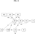
- FIG. 11 is a view illustrating an example of a general architecture of a 5th generation (5G) system.
- 5G 5th generation
- Access and mobility management function supports such functions as signaling between CN nodes for mobility between 3GPP access networks, termination of a radio access network (RAN) CP interface (N2), termination of NAS signaling (N1), registration management (registration area), idle mode UE reachability, support of network slicing, and SMF selection.
- RAN radio access network
- N1 termination of NAS signaling
- registration management registration area
- idle mode UE reachability support of network slicing
- SMF selection selection.
- AMF Access Management Function
- DN Data network
- PDU downlink protocol data unit
- PCF Policy control function
- Session management function provides a session management function, and when UE has a plurality of sessions, each session may be managed by different SMFs.
- SMF Session Management Function
- Unified data management stores a user' s subscription data, policy data and the like.
- UPF User plane function forwards a downlink PDU, which is received from a DN, to UE via (R)AN and forwards an uplink PDU, which is received from UE, to a DN via (R)AN.
- Application function operates with a 3GPP core network for service provision (e.g., for supporting functions like application effect on traffic routing, network capability exposure access, mutual operation with policy framework for policy control).
- Radio access network collectively refers to new radio access networks that support both evolved E-UTRA, which is an evolved version of 4G radio access, and a new radio (NR) access technology (e.g. eNB).
- NR new radio
- gNB supports functions for wireless resource management (that is, radio bearer control, radio admission control, connection mobility control, dynamic allocation of resources to UE in uplink/downlink (that is, scheduling)).
- User equipment means a user device.
- a conception link connecting NFs in a 5G system is defined as a reference point.
- N1 means a reference point between UE and AMF
- N2 means a reference point between (R)AN and AMF
- N3 means a reference point between (R)AN and UPF
- N4 means a reference point between SMF and UPF
- N6 means a reference point between UPF and a data network
- N9 means a reference point between 2 core UPFs
- N5 means a reference point between PCF and AF
- N7 means a reference point between SMF and PCF
- N24 means a reference point between PCF in a visited network and PCF in a home network
- N8 means a reference point between UDM and AMF
- N10 means a reference point between UDM and SMF
- N11 means a reference point between AMF and SMF
- N12 means a reference point between AMF and authentication server function (AUSF)
- N13 means a reference point between UDM and AUSF
- N14 means a reference point between 2 AMFs
- N15 means a reference point between
- the above description was based on an EPS system using eNB, but it may be replaced by a 5G system by using gNB instead of eNB, AMF instead of mobility management (MM) function of MME, SMF as SM function of S/P-GW, and UPF as user plane-related function of S/P-GW.
- gNB instead of eNB
- AMF mobility management
- MME mobility management
- SMF mobility management
- S/P-GW user plane-related function of S/P-GW.
- FIG. 12 is a view showing an example of a wireless device applicable to the present disclosure.
- the processor 1202a may receive a radio signal including second information/signal through the transceiver 1206a and then store information obtained from signal processing of the second information/signal in the memory 1204a.
- the memory 1204a may be coupled with the processor 1202a, and store a variety of information related to operation of the processor 1202a.
- the memory 1204a may store software code including instructions for performing all or some of the processes controlled by the processor 1202a or performing the descriptions, functions, procedures, proposals, methods and/or operational flowcharts disclosed herein.
- the processor 1202a and the memory 1204a may be part of a communication modem/circuit/chip designed to implement wireless communication technology (e.g., LTE or NR).
- one or more protocol layers may be implemented by one or more processors 1202a and 1202b.
- one or more processors 1202a and 1202b may implement one or more layers (e.g., functional layers such as PHY (physical), MAC (media access control), RLC (radio link control), PDCP (packet data convergence protocol), RRC (radio resource control), SDAP (service data adaptation protocol)).
- layers e.g., functional layers such as PHY (physical), MAC (media access control), RLC (radio link control), PDCP (packet data convergence protocol), RRC (radio resource control), SDAP (service data adaptation protocol)).
- the communication unit 1410 may transmit and receive signals (e.g., data, control signals, etc.) to and from other wireless devices or base stations.
- the control unit 1420 may control the components of the hand-held device 1400 to perform various operations.
- the control unit 1420 may include an application processor (AP).
- the memory unit 1430 may store data/parameters/program/code/instructions necessary to drive the hand-held device 1400. In addition, the memory unit 1430 may store input/output data/information, etc.
- the power supply unit 1440a may supply power to the hand-held device 1400 and include a wired/wireless charging circuit, a battery, etc.
- the interface unit 1440b may support connection between the hand-held device 1400 and another external device.
- the interface unit 1440b may include various ports (e.g., an audio input/output port and a video input/output port) for connection with the external device.
- the input/output unit 1440c may receive or output video information/signals, audio information/signals, data and/or user input information.
- the input/output unit 1440c may include a camera, a microphone, a user input unit, a display 1440d, a speaker and/or a haptic module.
- the input/output unit 1440c may acquire user input information/signal (e.g., touch, text, voice, image or video) from the user and store the user input information/signal in the memory unit 1430.
- the communication unit 1410 may convert the information/signal stored in the memory into a radio signal and transmit the converted radio signal to another wireless device directly or transmit the converted radio signal to a base station.
- the communication unit 1410 may receive a radio signal from another wireless device or the base station and then restore the received radio signal into original information/signal.
- the restored information/signal may be stored in the memory unit 1430 and then output through the input/output unit 1440c in various forms (e.g., text, voice, image, video and haptic).
- FIG. 15 is a view showing an example of a car or an autonomous driving car applicable to the present disclosure.
- FIG. 15 shows a car or an autonomous driving vehicle applicable to the present disclosure.
- the car or the autonomous driving car may be implemented as a mobile robot, a vehicle, a train, a manned/unmanned aerial vehicle (AV), a ship, etc. and the type of the car is not limited.
- AV manned/unmanned aerial vehicle
- the car or autonomous driving car 1500 may include an antenna unit (antenna) 1508, a communication unit (transceiver) 1510, a control unit (controller) 1520, a driving unit 1540a, a power supply unit (power supply) 1540b, a sensor unit 1540c, and an autonomous driving unit 1540d.
- the antenna unit 1550 may be configured as part of the communication unit 1510.
- the blocks 1510/1530/1540a to 1540d correspond to the blocks 1410/1430/1440 of FIG. 14 .
- the communication unit 1510 may transmit and receive signals (e.g., data, control signals, etc.) to and from external devices such as another vehicle, a base station (e.g., a base station, a road side unit, etc.), and a server.
- the control unit 1520 may control the elements of the car or autonomous driving car 1500 to perform various operations.
- the control unit 1520 may include an electronic control unit (ECU).
- the driving unit 1540a may drive the car or autonomous driving car 1500 on the ground.
- the driving unit 1540a may include an engine, a motor, a power train, wheels, a brake, a steering device, etc.
- the power supply unit 1540b may supply power to the car or autonomous driving car 1500, and include a wired/wireless charging circuit, a battery, etc.
- the sensor unit 1540c may obtain a vehicle state, surrounding environment information, user information, etc.
- the sensor unit 1540c may include an inertial navigation unit (IMU) sensor, a collision sensor, a wheel sensor, a speed sensor, an inclination sensor, a weight sensor, a heading sensor, a position module, a vehicle forward/reverse sensor, a battery sensor, a fuel sensor, a tire sensor, a steering sensor, a temperature sensor, a humidity sensor, an ultrasonic sensor, an illumination sensor, a brake pedal position sensor, and so on.
- IMU inertial navigation unit
- the autonomous driving sensor 1540d may implement technology for maintaining a driving lane, technology for automatically controlling a speed such as adaptive cruise control, technology for automatically driving the car along a predetermined route, technology for automatically setting a route when a destination is set and driving the car, etc.
- the communication unit 1510 may receive map data, traffic information data, etc. from an external server.
- the autonomous driving unit 1540d may generate an autonomous driving route and a driving plan based on the acquired data.
- the control unit 1520 may control the driving unit 1540a (e.g., speed/direction control) such that the car or autonomous driving car 1500 moves along the autonomous driving route according to the driving plane.
- the communication unit 1510 may aperiodically/periodically acquire latest traffic information data from an external server and acquire surrounding traffic information data from neighboring cars.
- the sensor unit 1540c may acquire a vehicle state and surrounding environment information.
- the autonomous driving unit 1540d may update the autonomous driving route and the driving plan based on newly acquired data/information.
- the communication unit 1510 may transmit information such as a vehicle location, an autonomous driving route, a driving plan, etc. to the external server.
- the external server may predict traffic information data using AI technology or the like based on the information collected from the cars or autonomous driving cars and provide the predicted traffic information data to the cars or autonomous driving cars.
- FIG. 16 is a view showing an example of a mobility applicable to the present disclosure.
- the mobility applied to the present disclosure may be implemented as at least one of a transportation means, a train, an aerial vehicle or a ship.
- the mobility applied to the present disclosure may be implemented in the other forms and is not limited to the above-described embodiments.
- the mobility 1600 may include a communication unit (transceiver) 1610, a control unit (controller) 1620, a memory unit (memory) 1630, an input/output unit 1640a and a positioning unit 1640b.
- the blocks 1610 to 1630/1640a to 1640b may corresponding to the blocks 1310 to 1330/1340 of FIG. 13 .
- the communication unit 1610 may transmit and receive signals (e.g., data, control signals, etc.) to and from external devices such as another mobility or a base station.
- the control unit 1620 may control the components of the mobility 1600 to perform various operations.
- the memory unit 1630 may store data/parameters/programs/code/instructions supporting the various functions of the mobility 1600.
- the input/output unit 1640a may output AR/VR objects based on information in the memory unit 1630.
- the input/output unit 1640a may include a HUD.
- the positioning unit 1640b may acquire the position information of the mobility 1600.
- the position information may include absolute position information of the mobility 1600, position information in a driving line, acceleration information, position information of neighboring vehicles, etc.
- the positioning unit 1640b may include a global positioning system (GPS) and various sensors.
- GPS global positioning system
- control unit 1620 may display a warning on the glass window of the mobility through the input/output unit 1640a. In addition, the control unit 1620 may broadcast a warning message for driving abnormality to neighboring mobilities through the communication unit 1610. Depending on situations, the control unit 1620 may transmit the position information of the mobility and information on driving/mobility abnormality to a related institution through the communication unit 1610.
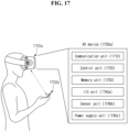
- FIG. 17 is a view showing an example of an XR device applicable to the present disclosure.
- the XR device may be implemented as a HMD, a head-up display (HUD) provided in a vehicle, a television, a smartphone, a computer, a wearable device, a home appliance, a digital signage, a vehicle, a robot, etc.
- HMD head-up display
- FIG. 17 is a view showing an example of an XR device applicable to the present disclosure.
- the XR device may be implemented as a HMD, a head-up display (HUD) provided in a vehicle, a television, a smartphone, a computer, a wearable device, a home appliance, a digital signage, a vehicle, a robot, etc.
- HUD head-up display
- the communication unit 1710 may transmit and receive signals (e.g., media data, control signals, etc.) to and from external devices such as another wireless device, a hand-held device or a media server.
- the media data may include video, image, sound, etc.
- the control unit 1720 may control the components of the XR device 1700a to perform various operations.
- the control unit 1720 may be configured to control and/or perform procedures such as video/image acquisition, (video/image) encoding, metadata generation and processing.
- the memory unit 1730 may store data/parameters/programs/code/instructions necessary to drive the XR device 1700a or generate an XR object.
- the input/output unit 1740a may acquire control information, data, etc. from the outside and output the generated XR object.
- the input/output unit 1740a may include a camera, a microphone, a user input unit, a display, a speaker and/or a haptic module.
- the sensor unit 1740b may obtain an XR device state, surrounding environment information, user information, etc.
- the sensor unit 1740b may include a proximity sensor, an illumination sensor, an acceleration sensor, a magnetic sensor, a gyro sensor, an inertia sensor, a red green blue (RGB) sensor, an infrared (IR) sensor, a finger scan sensor, an ultrasonic sensor, an optical sensor, a microphone and/or a radar.
- the power supply unit 1740c may supply power to the XR device 1700a and include a wired/wireless charging circuit, a battery, etc.
- the memory unit 1730 of the XR device 1700a may include information (e.g., data, etc.) necessary to generate an XR object (e.g., AR/VR/MR object).
- the input/output unit 1740a may acquire an instruction for manipulating the XR device 1700a from a user, and the control unit 1720 may drive the XR device 1700a according to the driving instruction of the user. For example, when the user wants to watch a movie, news, etc. through the XR device 1700a, the control unit 1720 may transmit content request information to another device (e.g., a hand-held device 1700b) or a media server through the communication unit 1730.
- another device e.g., a hand-held device 1700b
- a media server e.g., a media server
- the communication unit 1730 may download/stream content such as a movie or news from another device (e.g., the hand-held device 1700b) or the media server to the memory unit 1730.
- the control unit 1720 may control and/or perform procedures such as video/image acquisition, (video/image) encoding, metadata generation/processing, etc. with respect to content, and generate/output an XR object based on information on a surrounding space or a real object acquired through the input/output unit 1740a or the sensor unit 1740b.
- the XR device 1700a may be wirelessly connected with the hand-held device 1700b through the communication unit 1710, and operation of the XR device 1700a may be controlled by the hand-held device 1700b.
- the hand-held device 1700b may operate as a controller for the XR device 1700a.
- the XR device 1700a may acquire three-dimensional position information of the hand-held device 1700b and then generate and output an XR object corresponding to the hand-held device 1700b.
- FIG. 18 is a view showing an example of a robot applicable to the present disclosure.
- the robot may be classified into industrial, medical, household, military, etc. according to the purpose or field of use.
- the robot 1800 may include a communication unit (transceiver) 1810, a control unit (controller) 1820, a memory unit (memory) 1830, an input/output unit 1840a, sensor unit 1840b and a driving unit 1840c.
- blocks 1810 to 1830/1840a to 1840c may correspond to the blocks 1310 to 1330/1340 of FIG. 13 , respectively.
- the communication unit 1810 may transmit and receive signals (e.g., driving information, control signals, etc.) to and from external devices such as another wireless device, another robot or a control server.
- the control unit 1820 may control the components of the robot 1800 to perform various operations.
- the memory unit 1830 may store data/parameters/programs/code/instructions supporting various functions of the robot 1800.
- the input/output unit 1840a may acquire information from the outside of the robot 1800 and output information to the outside of the robot 1800.
- the input/output unit 1840a may include a camera, a microphone, a user input unit, a display, a speaker and/or a haptic module.
- the sensor unit 1840b may obtain internal information, surrounding environment information, user information, etc. of the robot 1800.
- the sensor unit 1840b may include a proximity sensor, an illumination sensor, an acceleration sensor, a magnetic sensor, a gyro sensor, an inertia sensor, an infrared (IR) sensor, a finger scan sensor, an ultrasonic sensor, an optical sensor, a microphone and/or a radar.
- the driving unit 1840c may perform various physical operations such as movement of robot joints. In addition, the driving unit 1840c may cause the robot 1800 to run on the ground or fly in the air.
- the driving unit 1840c may include an actuator, a motor, wheels, a brake, a propeller, etc.
- a terminal may perform discontinuous reception (DRX) in RRC idle (RRC_IDLE) and RRC inactive (RRC_INACTIVE) states to reduce power consumption.
- the terminal monitors one paging occasion (PO) per DRX cycle.
- the terminal may receive paging downlink control information (DCI) in a paging occasion (PO), which is a PDCCH monitoring opportunity that can be configured in multiple time slots (e.g. subframes or OFDM symbols).
- DCI downlink control information
- a base station may perform multi-beam transmission.
- the base station may repeatedly transmit a same paging message in all beams of an entire pattern.
- the terminal may receive a paging message by selecting a specific beam among beams transmitted by the base station, and a corresponding terminal operation may be different depending on an implementation of the terminal.
- the paging message may be classified into radio access network (RAN) paging and core network (CN) paging.
- RAN radio access network
- CN core network
- the RAN paging message and the CN paging message may be the same paging message.
- the RRC idle state terminal and the RRC inactive state terminal described above may operate differently.
- the RRC inactive state terminal is in a state connected to the CN and may be deactivated in the RAN.
- the CN may determine that the terminal is connected to a specific RAN. In this case, when signaling occurs in the terminal, the CN may consider that the terminal is in a connected state and may transfer signaling for the terminal to the RAN.
- the RAN since the RRC inactive state terminal is in an inactive state in the RAN, the RAN may generate a paging message to perform the above-described RAN paging.
- the RRC idle state terminal may be in an inactive state both in the RAN and in the CN. Accordingly, when signaling occurs in the terminal, the CN may perform the above-described CN paging based on a tracking area (TA).
- TA tracking area
- the terminal may perform a RRC Connection Resume procedure.
- the terminal transitions from the RRC inactive state to the RRC idle state and provides information on the transition state to the CN.
- a terminal monitors a (i s + 1)th PO in which a first PO starts in a PF.
- PDCCH monitoring opportunities for paging that do not overlap with uplink symbols are numbered consecutively starting from 0 allocated to a first PDCCH monitoring situation for paging in the PF.
- the (i s + 1)th PO may be a set from a PDCCH monitoring opportunity indicated by "firstPDCCH-MonitoringOccasionOfPO" (e.g.
- the above-described parameters, N, Ns, "first-PDCCH-MonitoringOccassionOfPO", PF offset , and a default DRX cycle are signaled in SIB1.
- 5G-S-TMSI is a string with 48-bit length, and in the above-described equation, "5G-S-TMSI" should be interpreted as a binary number indicating that a leftmost bit is a most important bit.
- coordination may be difficult between networks to which a terminal with a plurality of USIMs is registered. That is, the networks to which the terminal is registered may operate with each system independently without coordination with each other. Accordingly, each of the networks may transmit paging without recognizing other networks, and the terminal may receive paging from respective networks at the same time.
- a hardware implementation of the terminal may receive one paging but not a paging channel simultaneously, a concrete method for performing paging may be needed to prevent service quality of the terminal from being degraded.
- a terminal may obtain information on a paging application server (PAF) set by each network service provider during registration.
- the terminal may obtain the information on a PAF set by each network service provider by using a preset value.
- the terminal may obtain PAF information for each network service provider corresponding to each USIM.
- the terminal may be allocated an Internet protocol (IP) address A1 from SMF1 while being registered to a mobile communication service provider A (or network A).
- IP Internet protocol
- the terminal may receive an IP address A2 of PAF1.
- the terminal may be allocated an IP address B1 from SMF2 while being registered to a mobile communication service provider B (or network B).
- the terminal may receive an IP address B2 of PAF2.
- the terminal may try registration to another system by using data connectivity through each system.
- the terminal may register A1, which is an IP address allocated from SMF1, to PAF2.
- the terminal may register the IP address B1 allocated from SMF2 to PAF1.
- the terminal may transition to at least any one of RRC inactive state or RRC idle state based on an instruction of a RAN. After transitioning based on what is described above, the terminal may monitor a paging channel of each service provider (or network).
- each service provider or network.
- this is merely one example, and the present disclosure is not limited to the above-described embodiment.
- RAN paging for indicating a new RRC configuration setting to a terminal may start in a RAN node of the mobile communication service provider A (hereinafter, node gNB-A).
- node gNB-A a RAN node of the mobile communication service provider A
- the terminal may not receive the paging due to an operation of a system of the mobile communication service provider B. That is, the terminal may not receive the paging of the mobile communication service provider A because of the system of the mobile communication service provider B. Accordingly, the terminal may not respond to the above-described node eNB-A for a certain period of time.
- the node eNB-A may determine that the above-described RAN paging fails, and may request paging for the terminal to a CN.
- the node gNB-A may transfer information on the failure to the CN, which is not limited to the above-described embodiment.
- the CN may transfer signaling from the node gNB-A to the terminal or notify information on the connection failure to the failure.
- the CN may check registration information of the terminal based on the information received from the node eNB-A.
- the mobile communication service provider A may check whether or not there is information that the terminal registers to PAF1, based on the terminal registration information forwarded to the CN.
- the CN may request PAF 1 to forward any one of paging-related information for the terminal, RRC connected state transition request information, re-registration request information, connection request information, and paging performance reason information to the terminal.
- PAF1 may forward information received from the CN to the terminal through information that the terminal indicated previously (e.g. IP address B1).
- the terminal may determine whether or not to switch to the system of the mobile communication service provider A. As an example, when system switching is necessary based on the above-described information or a crucial operation occurs to the system of the mobile communication service provider A, the terminal may switch to the system of the mobile communication service provider A and perform a necessary operation.
- the above-described process may be performed in case a terminal is registered to a plurality of systems beforehand.
- the above-described process may be performed in case a terminal indicates information on a multi-SIM operation or registration information on a multi-SIM operation.
- the above-described process may be performed when a previous network configures a corresponding operation to each network, which is not limited to the above-described embodiment.
- the above-described process may be used to indicate corresponding information to a terminal operating based on multi-SIM, and in this case, relevant may be used instead.
- a terminal operates based on multi-SIM or the terminal is registered to a plurality of systems
- the CN may forward the data or signaling to the terminal by using another system (or a communication network of another system) or an AF.
- another system or a communication network of another system
- an AF a communication network of another system
- the terminal may forward the data or signaling to the terminal by using another system (or a communication network of another system) or an AF.
- the terminal may be a case in which the terminal does not receive a paging message or does not respond to a signaling message so that a wireless network requests the CN to forward information to the terminal or to perform a paging process, as described above.
- a network may suspend paging according to a temporary suspension request that the terminal transmits based on the first system. That is, the network may not transfer paging to the terminal for a predetermined time even when data to be transmitted to the terminal is generated based on the first system. That is, the network may transmit paging after the predetermined time, and the terminal may check paging for the above-described first system after a predetermined time based on the above-described temporary suspension request.
- the information that requires paging reception may be forwarded based on at least any one of a logical channel, a packet data unit (PDU) session, a network slice, a data network name (DNN), and IP multimedia subsystem (IMS) service information.
- PDU packet data unit
- DNN data network name
- IMS IP multimedia subsystem
- the network may transmit paging to the terminal.
- the above-described operation may be applied to a wireless access network and a core network.
- an information granularity in which the terminal wants to receive paging in an existing system, may be at least any one of a logical channel, a packet data unit (PDU) session, a network slice, a data network name (DNN), and IP multimedia subsystem (IMS) service information.
- PDU packet data unit
- DNN data network name
- IMS IP multimedia subsystem
- the UE 1910 may provide information associated with handling of data or signaling, which occurs to the UE 1910, to the first network 1940, while leaving the first network 1940.
- the UE 1910 may forward paging condition-related information to a network, while transitioning from the first network 1940 to the second network 1950.
- the temporary suspension request may further include identifier information for information indicating data desiring to receive paging.
- the temporary suspension request may further include identifier information associated with the logical channel.
- the temporary suspension request may further include identifier information associated with the PDU session, which is not limited to the above-described embodiment.
- the UE 1910 may transition from the second network 1950 to the first network 1940 again, but the present disclosure is not limited to the above-described embodiment.
- FIG. 20 a view illustrating a terminal operation method applied to the present disclosure.
- a terminal operating based on a plurality of networks may establish a connection to a first network (S2010).
- the terminal receives a paging message from a second network (S2020)
- the terminal transmits a message for indicating temporary suspension of data communication with the first network to the first network (S2030).
- a process of the terminal controls a transceiver, and the transceiver receives a paging message from the second network. That is, the processor of the terminal controls the transceiver to receive a paging message from the second network.
- the transceiver transmits a message for indicating temporary suspension of data communication to the first network.
- the processor of the terminal controls the transceiver to transmit a message for indicating temporary suspension of data communication to the first network.
- the message for indicating temporary suspension of data communication with the first network may be a temporary suspension request message.
- the message for indicating temporary suspension of data communication with the first network may be a message for indicating leave from the first network. That is, the message for indicating temporary suspension of data communication with the first network may be a message to the effect that the terminal suspends data communication with the first network for a predetermined period of time in order to perform data communication with another network, and this is not limited to any specific term.
- the first network is a network corresponding a first SIM
- the second network is a network corresponding to a second SIM.
- a network may be a non-public network not corresponding to SIM and is not limited to the above-described embodiment.
- the description below assumes a network corresponding to SIM.
- the terminal receives a paging message from the second network after having established a connection to the first network, if a priority of data corresponding to the paging message is higher than a preset priority, the terminal transitions from the first network to the second network. On the other hand, in case a priority of data corresponding to the paging message is lower than a preset priority, a connection to the first network may be maintained.
- the temporary suspension request includes paging-related information of the first network.
- the terminal receives a paging message from the first network after transitioning to the second network, the terminal determines whether or not to transition to the first network based on the paging-related information of the first network included in the temporary suspension request.
- the paging-related information of the first network is information indicating data the terminal desires to receive paging among data that occur from the first network to the terminal after the terminal transitions to the second network.
- the paging-related information may indicate the data desiring to receive paging based on at least any one of a logical channel, a packet data unit (PDU) session, a network slice, a data network name (DNN), and IP multimedia subsystem (IMS) service information, as described above.
- PDU packet data unit
- DNN data network name
- IMS IP multimedia subsystem
- the paging-related information may further include identifier information for information indicating data desiring to receive paging.
- the paging-related information may further include identifier information associated with the PDU session, as described above.
- the terminal in case the terminal receives the paging message from the first network after the terminal transitions to the second network, if the paging message corresponds to the paging-related information of the first network, the terminal transitions from the second network to the first network.
- the terminal may maintain connection with the second network.
- the terminal after the terminal transitions to the second network, when a predetermined time passes or the terminal receives a message indicating resumption of the data communication with the first network, the terminal may transition to the first network.
- the first network may establish a connection to a terminal operating based on a plurality of networks.
- the terminal may indicate to the first network through signaling to the effect that the terminal operates based on a plurality of networks, but this is not limited to the above-described embodiment.
- the first network may suspend the connection to the terminal based on a temporary suspension request.
- the first network may recognize that the terminal performs connection to the second network, that is, another network.
- the temporary suspension request may include paging condition-related information of a network. Based on paging-related information included in the temporary suspension request, the first network may determine whether or not to transmit a paging message to the terminal.
Landscapes
- Engineering & Computer Science (AREA)
- Computer Networks & Wireless Communication (AREA)
- Signal Processing (AREA)
- Computer Security & Cryptography (AREA)
- Mobile Radio Communication Systems (AREA)
- Telephonic Communication Services (AREA)
Priority Applications (1)
| Application Number | Priority Date | Filing Date | Title |
|---|---|---|---|
| EP25160486.4A EP4543109A3 (en) | 2019-11-06 | 2020-10-28 | Method and apparatus for transmitting and receiving signals of user equipment and base station in wireless communication system |
Applications Claiming Priority (2)
| Application Number | Priority Date | Filing Date | Title |
|---|---|---|---|
| KR20190141255 | 2019-11-06 | ||
| PCT/KR2020/014824 WO2021091155A1 (ko) | 2019-11-06 | 2020-10-28 | 무선 통신 시스템에서 단말 및 기지국의 신호 송수신 방법 및 장치 |
Related Child Applications (2)
| Application Number | Title | Priority Date | Filing Date |
|---|---|---|---|
| EP25160486.4A Division-Into EP4543109A3 (en) | 2019-11-06 | 2020-10-28 | Method and apparatus for transmitting and receiving signals of user equipment and base station in wireless communication system |
| EP25160486.4A Division EP4543109A3 (en) | 2019-11-06 | 2020-10-28 | Method and apparatus for transmitting and receiving signals of user equipment and base station in wireless communication system |
Publications (3)
| Publication Number | Publication Date |
|---|---|
| EP4057721A1 EP4057721A1 (en) | 2022-09-14 |
| EP4057721A4 EP4057721A4 (en) | 2023-11-08 |
| EP4057721B1 true EP4057721B1 (en) | 2025-04-09 |
Family
ID=75849764
Family Applications (2)
| Application Number | Title | Priority Date | Filing Date |
|---|---|---|---|
| EP20885842.3A Active EP4057721B1 (en) | 2019-11-06 | 2020-10-28 | Methods and terminal for paging a multi-sim terminal |
| EP25160486.4A Pending EP4543109A3 (en) | 2019-11-06 | 2020-10-28 | Method and apparatus for transmitting and receiving signals of user equipment and base station in wireless communication system |
Family Applications After (1)
| Application Number | Title | Priority Date | Filing Date |
|---|---|---|---|
| EP25160486.4A Pending EP4543109A3 (en) | 2019-11-06 | 2020-10-28 | Method and apparatus for transmitting and receiving signals of user equipment and base station in wireless communication system |
Country Status (5)
| Country | Link |
|---|---|
| US (1) | US12335911B2 (ko) |
| EP (2) | EP4057721B1 (ko) |
| KR (1) | KR102505706B1 (ko) |
| CN (1) | CN114616878B (ko) |
| WO (1) | WO2021091155A1 (ko) |
Families Citing this family (6)
| Publication number | Priority date | Publication date | Assignee | Title |
|---|---|---|---|---|
| CN114071715A (zh) * | 2020-08-06 | 2022-02-18 | 北京三星通信技术研究有限公司 | 用于寻呼的方法和设备 |
| CN114745677B (zh) * | 2021-01-08 | 2023-05-16 | 维沃移动通信有限公司 | 路径处理方法、装置、终端、网络设备和存储介质 |
| CN115580942B (zh) * | 2022-09-27 | 2026-04-03 | 维沃移动通信有限公司 | 网络连接方法、装置、电子设备和可读存储介质 |
| US12550099B2 (en) * | 2023-08-29 | 2026-02-10 | Qualcomm Incorporated | Enhanced paging services with identity management for wireless networks |
| US20250081039A1 (en) * | 2023-09-05 | 2025-03-06 | Dish Wireless L.L.C. | Intelligent simultaneous core |
| US20250089019A1 (en) * | 2023-09-07 | 2025-03-13 | Qualcomm Incorporated | Paging for network-based user equipment (ue)-to-ue communication |
Family Cites Families (27)
| Publication number | Priority date | Publication date | Assignee | Title |
|---|---|---|---|---|
| US8630667B2 (en) | 2009-10-23 | 2014-01-14 | Apple Inc. | Methods and apparatus for paging reception in multimode wireless networks |
| US9161233B2 (en) * | 2010-03-30 | 2015-10-13 | Qualcomm Incorporated | Method and apparatus to facilitate support for multi-radio coexistence |
| US20130150014A1 (en) * | 2011-12-12 | 2013-06-13 | Broadcom Corporation | Background Paging Monitoring For Multiple SIM User Equipment |
| CN103517454A (zh) * | 2012-06-27 | 2014-01-15 | 联发科技股份有限公司 | 增强信令连接释放指示处理方法 |
| DE112013002607B4 (de) * | 2012-06-28 | 2021-10-07 | Apple Inc. | Antworten auf eine Funkrufnachricht |
| WO2014058245A1 (ko) * | 2012-10-10 | 2014-04-17 | 엘지전자 주식회사 | 추적 영역 갱신 방법 및 단말 |
| US9072070B2 (en) * | 2012-11-29 | 2015-06-30 | Intel Mobile Communications GmbH | Mobile wireless devices and methods of operation |
| CN103999508B (zh) * | 2012-11-30 | 2019-09-03 | 华为技术有限公司 | 迁移方法及装置 |
| WO2017069598A1 (ko) | 2015-10-23 | 2017-04-27 | 엘지전자(주) | 무선 통신 시스템에서 단말의 아이들 모드 시그널링 감소를 제어하기 위한 방법 및 이를 위한 장치 |
| WO2018005419A1 (en) * | 2016-06-30 | 2018-01-04 | Intel IP Corporation | Optimized paging mechanism for ip multimedia subsystem (ims) |
| CN109479309B (zh) * | 2016-07-13 | 2022-10-11 | 三星电子株式会社 | 在移动通信中使用的接入控制方法和装置 |
| KR102463290B1 (ko) * | 2016-08-02 | 2022-11-04 | 삼성전자 주식회사 | 차세대 이동통신 시스템에서 네트워크 소모 전력을 효과적으로 절감시키는 방법 및 장치 |
| US20180220329A1 (en) | 2017-01-28 | 2018-08-02 | Qualcomm Incorporated | System and Methods for Improving Performance in a Multi-SIM Wireless Communication Device Using Voice-Over-Wireless Local Area Network Service |
| CN115102588B (zh) * | 2017-05-05 | 2024-05-14 | 瑞典爱立信有限公司 | 5g系统中的寻呼策略区分 |
| EP4593520A3 (en) * | 2017-06-16 | 2025-10-29 | Telefonaktiebolaget LM Ericsson (publ) | Resuming a connection in a wireless communication system |
| BR112020002493A2 (pt) | 2017-08-09 | 2020-08-04 | Ntt Docomo, Inc. | estação rádio base e método de radiocomunicação |
| WO2020209620A1 (en) * | 2019-04-09 | 2020-10-15 | Samsung Electronics Co., Ltd. | Method and ue for managing paging procedure in wireless communication network |
| US12302231B2 (en) * | 2019-04-09 | 2025-05-13 | Samsung Electronics Co., Ltd. | Method and system of UE for switching between plurality of SIM networks |
| US11910482B2 (en) * | 2019-04-16 | 2024-02-20 | Asustek Computer Inc. | Method and apparatus for UE reporting for multi-USIM in a wireless communication system |
| CN110351704A (zh) * | 2019-05-29 | 2019-10-18 | 努比亚技术有限公司 | 一种寻呼控制方法、双卡双待终端及计算机可读存储介质 |
| CN118785369A (zh) * | 2019-06-17 | 2024-10-15 | 交互数字专利控股公司 | 用于具有多个usim的wtru的寻呼方法 |
| WO2020252621A1 (en) * | 2019-06-17 | 2020-12-24 | Qualcomm Incorporated | Techniques for managing sessions in multiple-subscription wireless communications |
| KR20210020384A (ko) * | 2019-08-14 | 2021-02-24 | 삼성전자주식회사 | 차세대 이동 통신 시스템에서 복수 개의 sim을 지원하는 단말의 페이징 송수신 방법 및 장치 |
| US12615607B2 (en) * | 2019-09-06 | 2026-04-28 | Lenovo (Singapore) Pte. Ltd. | Connection suspension for multiple SIMs |
| US11452067B2 (en) * | 2019-09-25 | 2022-09-20 | Qualcomm Incorporated | Secure paging for service prioritization |
| EP4489489A3 (en) * | 2019-10-11 | 2025-01-15 | Lenovo (Singapore) Pte. Ltd. | Paging for multiple sims |
| EP4054247B1 (en) * | 2019-10-29 | 2025-10-15 | Beijing Xiaomi Mobile Software Co., Ltd. | Method and apparatus for connection establishment, base station, user equipment, and core network device |
-
2020
- 2020-10-28 WO PCT/KR2020/014824 patent/WO2021091155A1/ko not_active Ceased
- 2020-10-28 EP EP20885842.3A patent/EP4057721B1/en active Active
- 2020-10-28 KR KR1020227004467A patent/KR102505706B1/ko active Active
- 2020-10-28 CN CN202080076042.7A patent/CN114616878B/zh active Active
- 2020-10-28 US US17/772,890 patent/US12335911B2/en active Active
- 2020-10-28 EP EP25160486.4A patent/EP4543109A3/en active Pending
Also Published As
| Publication number | Publication date |
|---|---|
| CN114616878A (zh) | 2022-06-10 |
| CN114616878B (zh) | 2024-01-19 |
| EP4057721A4 (en) | 2023-11-08 |
| WO2021091155A1 (ko) | 2021-05-14 |
| KR20220028134A (ko) | 2022-03-08 |
| KR102505706B1 (ko) | 2023-03-03 |
| EP4543109A2 (en) | 2025-04-23 |
| EP4543109A3 (en) | 2025-06-18 |
| US20220377702A1 (en) | 2022-11-24 |
| EP4057721A1 (en) | 2022-09-14 |
| US12335911B2 (en) | 2025-06-17 |
Similar Documents
| Publication | Publication Date | Title |
|---|---|---|
| US12418876B2 (en) | Method and device for performing registration in network in wireless communication system | |
| US11917580B2 (en) | Method for transmitting and receiving paging signal in wireless communication system and apparatus therefor | |
| US10856248B2 (en) | Method for selecting network providing restricted local operator service in wireless communication system and apparatus thereof | |
| US11553332B2 (en) | Method and device for controlling data transmission state in wireless communication system | |
| US12137485B2 (en) | Method for transmitting/receiving PDB-related signal in wireless communication system and device therefor | |
| US12063593B2 (en) | Method for terminal to connect to network in wireless communication system | |
| US12294973B2 (en) | Method for providing communication service in wireless communication system | |
| EP3780902B1 (en) | Method for transmitting v2x data in wireless communication system, and device therefor | |
| EP4057721B1 (en) | Methods and terminal for paging a multi-sim terminal | |
| US20220038946A1 (en) | Method by which nwdaf transmits and receives signal in wireless communication system, and device therefor | |
| EP4057766B1 (en) | Method and device for controlling configuration related to sidelink communication in wireless communication system | |
| US12376013B2 (en) | PWS service method in NPN | |
| US20210321320A1 (en) | Method and apparatus for transmitting data in wireless communication system | |
| US20220361039A1 (en) | Operation method related to sidelink transmission and reception of ue in wireless communication system, and device therefor |
Legal Events
| Date | Code | Title | Description |
|---|---|---|---|
| STAA | Information on the status of an ep patent application or granted ep patent |
Free format text: STATUS: THE INTERNATIONAL PUBLICATION HAS BEEN MADE |
|
| PUAI | Public reference made under article 153(3) epc to a published international application that has entered the european phase |
Free format text: ORIGINAL CODE: 0009012 |
|
| STAA | Information on the status of an ep patent application or granted ep patent |
Free format text: STATUS: REQUEST FOR EXAMINATION WAS MADE |
|
| 17P | Request for examination filed |
Effective date: 20220520 |
|
| AK | Designated contracting states |
Kind code of ref document: A1 Designated state(s): AL AT BE BG CH CY CZ DE DK EE ES FI FR GB GR HR HU IE IS IT LI LT LU LV MC MK MT NL NO PL PT RO RS SE SI SK SM TR |
|
| DAV | Request for validation of the european patent (deleted) | ||
| DAX | Request for extension of the european patent (deleted) | ||
| REG | Reference to a national code |
Ref country code: DE Ref legal event code: R079 Free format text: PREVIOUS MAIN CLASS: H04W0068020000 Ipc: H04W0060000000 Ref document number: 602020049311 Country of ref document: DE |
|
| A4 | Supplementary search report drawn up and despatched |
Effective date: 20231006 |
|
| RIC1 | Information provided on ipc code assigned before grant |
Ipc: H04W 88/06 20090101ALN20230929BHEP Ipc: H04W 68/00 20090101ALI20230929BHEP Ipc: H04W 48/18 20090101ALI20230929BHEP Ipc: H04W 60/00 20090101AFI20230929BHEP |
|
| STAA | Information on the status of an ep patent application or granted ep patent |
Free format text: STATUS: EXAMINATION IS IN PROGRESS |
|
| 17Q | First examination report despatched |
Effective date: 20240515 |
|
| GRAP | Despatch of communication of intention to grant a patent |
Free format text: ORIGINAL CODE: EPIDOSNIGR1 |
|
| STAA | Information on the status of an ep patent application or granted ep patent |
Free format text: STATUS: GRANT OF PATENT IS INTENDED |
|
| RIC1 | Information provided on ipc code assigned before grant |
Ipc: H04W 88/06 20090101ALN20241017BHEP Ipc: H04W 68/00 20090101ALI20241017BHEP Ipc: H04W 48/18 20090101ALI20241017BHEP Ipc: H04W 60/00 20090101AFI20241017BHEP |
|
| RIC1 | Information provided on ipc code assigned before grant |
Ipc: H04W 88/06 20090101ALN20241021BHEP Ipc: H04W 68/00 20090101ALI20241021BHEP Ipc: H04W 48/18 20090101ALI20241021BHEP Ipc: H04W 60/00 20090101AFI20241021BHEP |
|
| INTG | Intention to grant announced |
Effective date: 20241104 |
|
| GRAS | Grant fee paid |
Free format text: ORIGINAL CODE: EPIDOSNIGR3 |
|
| GRAA | (expected) grant |
Free format text: ORIGINAL CODE: 0009210 |
|
| STAA | Information on the status of an ep patent application or granted ep patent |
Free format text: STATUS: THE PATENT HAS BEEN GRANTED |
|
| AK | Designated contracting states |
Kind code of ref document: B1 Designated state(s): AL AT BE BG CH CY CZ DE DK EE ES FI FR GB GR HR HU IE IS IT LI LT LU LV MC MK MT NL NO PL PT RO RS SE SI SK SM TR |
|
| REG | Reference to a national code |
Ref country code: GB Ref legal event code: FG4D |
|
| REG | Reference to a national code |
Ref country code: CH Ref legal event code: EP |
|
| REG | Reference to a national code |
Ref country code: DE Ref legal event code: R096 Ref document number: 602020049311 Country of ref document: DE |
|
| REG | Reference to a national code |
Ref country code: IE Ref legal event code: FG4D |
|
| REG | Reference to a national code |
Ref country code: NL Ref legal event code: MP Effective date: 20250409 |
|
| PG25 | Lapsed in a contracting state [announced via postgrant information from national office to epo] |
Ref country code: NL Free format text: LAPSE BECAUSE OF FAILURE TO SUBMIT A TRANSLATION OF THE DESCRIPTION OR TO PAY THE FEE WITHIN THE PRESCRIBED TIME-LIMIT Effective date: 20250409 |
|
| REG | Reference to a national code |
Ref country code: AT Ref legal event code: MK05 Ref document number: 1784746 Country of ref document: AT Kind code of ref document: T Effective date: 20250409 |
|
| PG25 | Lapsed in a contracting state [announced via postgrant information from national office to epo] |
Ref country code: FI Free format text: LAPSE BECAUSE OF FAILURE TO SUBMIT A TRANSLATION OF THE DESCRIPTION OR TO PAY THE FEE WITHIN THE PRESCRIBED TIME-LIMIT Effective date: 20250409 Ref country code: ES Free format text: LAPSE BECAUSE OF FAILURE TO SUBMIT A TRANSLATION OF THE DESCRIPTION OR TO PAY THE FEE WITHIN THE PRESCRIBED TIME-LIMIT Effective date: 20250409 Ref country code: PT Free format text: LAPSE BECAUSE OF FAILURE TO SUBMIT A TRANSLATION OF THE DESCRIPTION OR TO PAY THE FEE WITHIN THE PRESCRIBED TIME-LIMIT Effective date: 20250811 |
|
| REG | Reference to a national code |
Ref country code: LT Ref legal event code: MG9D |
|
| PG25 | Lapsed in a contracting state [announced via postgrant information from national office to epo] |
Ref country code: NO Free format text: LAPSE BECAUSE OF FAILURE TO SUBMIT A TRANSLATION OF THE DESCRIPTION OR TO PAY THE FEE WITHIN THE PRESCRIBED TIME-LIMIT Effective date: 20250709 Ref country code: GR Free format text: LAPSE BECAUSE OF FAILURE TO SUBMIT A TRANSLATION OF THE DESCRIPTION OR TO PAY THE FEE WITHIN THE PRESCRIBED TIME-LIMIT Effective date: 20250710 |
|
| PG25 | Lapsed in a contracting state [announced via postgrant information from national office to epo] |
Ref country code: PL Free format text: LAPSE BECAUSE OF FAILURE TO SUBMIT A TRANSLATION OF THE DESCRIPTION OR TO PAY THE FEE WITHIN THE PRESCRIBED TIME-LIMIT Effective date: 20250409 |
|
| PG25 | Lapsed in a contracting state [announced via postgrant information from national office to epo] |
Ref country code: BG Free format text: LAPSE BECAUSE OF FAILURE TO SUBMIT A TRANSLATION OF THE DESCRIPTION OR TO PAY THE FEE WITHIN THE PRESCRIBED TIME-LIMIT Effective date: 20250409 |
|
| PGFP | Annual fee paid to national office [announced via postgrant information from national office to epo] |
Ref country code: GB Payment date: 20250909 Year of fee payment: 6 |
|
| PG25 | Lapsed in a contracting state [announced via postgrant information from national office to epo] |
Ref country code: HR Free format text: LAPSE BECAUSE OF FAILURE TO SUBMIT A TRANSLATION OF THE DESCRIPTION OR TO PAY THE FEE WITHIN THE PRESCRIBED TIME-LIMIT Effective date: 20250409 |
|
| PG25 | Lapsed in a contracting state [announced via postgrant information from national office to epo] |
Ref country code: AT Free format text: LAPSE BECAUSE OF FAILURE TO SUBMIT A TRANSLATION OF THE DESCRIPTION OR TO PAY THE FEE WITHIN THE PRESCRIBED TIME-LIMIT Effective date: 20250409 |
|
| PGFP | Annual fee paid to national office [announced via postgrant information from national office to epo] |
Ref country code: FR Payment date: 20250909 Year of fee payment: 6 |
|
| PG25 | Lapsed in a contracting state [announced via postgrant information from national office to epo] |
Ref country code: RS Free format text: LAPSE BECAUSE OF FAILURE TO SUBMIT A TRANSLATION OF THE DESCRIPTION OR TO PAY THE FEE WITHIN THE PRESCRIBED TIME-LIMIT Effective date: 20250709 |
|
| PG25 | Lapsed in a contracting state [announced via postgrant information from national office to epo] |
Ref country code: IS Free format text: LAPSE BECAUSE OF FAILURE TO SUBMIT A TRANSLATION OF THE DESCRIPTION OR TO PAY THE FEE WITHIN THE PRESCRIBED TIME-LIMIT Effective date: 20250809 |
|
| PG25 | Lapsed in a contracting state [announced via postgrant information from national office to epo] |
Ref country code: LV Free format text: LAPSE BECAUSE OF FAILURE TO SUBMIT A TRANSLATION OF THE DESCRIPTION OR TO PAY THE FEE WITHIN THE PRESCRIBED TIME-LIMIT Effective date: 20250409 |
|
| PGFP | Annual fee paid to national office [announced via postgrant information from national office to epo] |
Ref country code: DE Payment date: 20250908 Year of fee payment: 6 |
|
| REG | Reference to a national code |
Ref country code: DE Ref legal event code: R097 Ref document number: 602020049311 Country of ref document: DE |
|
| PG25 | Lapsed in a contracting state [announced via postgrant information from national office to epo] |
Ref country code: SM Free format text: LAPSE BECAUSE OF FAILURE TO SUBMIT A TRANSLATION OF THE DESCRIPTION OR TO PAY THE FEE WITHIN THE PRESCRIBED TIME-LIMIT Effective date: 20250409 Ref country code: DK Free format text: LAPSE BECAUSE OF FAILURE TO SUBMIT A TRANSLATION OF THE DESCRIPTION OR TO PAY THE FEE WITHIN THE PRESCRIBED TIME-LIMIT Effective date: 20250409 |
|
| PG25 | Lapsed in a contracting state [announced via postgrant information from national office to epo] |
Ref country code: CZ Free format text: LAPSE BECAUSE OF FAILURE TO SUBMIT A TRANSLATION OF THE DESCRIPTION OR TO PAY THE FEE WITHIN THE PRESCRIBED TIME-LIMIT Effective date: 20250409 |
|
| PG25 | Lapsed in a contracting state [announced via postgrant information from national office to epo] |
Ref country code: EE Free format text: LAPSE BECAUSE OF FAILURE TO SUBMIT A TRANSLATION OF THE DESCRIPTION OR TO PAY THE FEE WITHIN THE PRESCRIBED TIME-LIMIT Effective date: 20250409 |
|
| PG25 | Lapsed in a contracting state [announced via postgrant information from national office to epo] |
Ref country code: SK Free format text: LAPSE BECAUSE OF FAILURE TO SUBMIT A TRANSLATION OF THE DESCRIPTION OR TO PAY THE FEE WITHIN THE PRESCRIBED TIME-LIMIT Effective date: 20250409 |
|
| PG25 | Lapsed in a contracting state [announced via postgrant information from national office to epo] |
Ref country code: IT Free format text: LAPSE BECAUSE OF FAILURE TO SUBMIT A TRANSLATION OF THE DESCRIPTION OR TO PAY THE FEE WITHIN THE PRESCRIBED TIME-LIMIT Effective date: 20250409 |
|
| PG25 | Lapsed in a contracting state [announced via postgrant information from national office to epo] |
Ref country code: RO Free format text: LAPSE BECAUSE OF FAILURE TO SUBMIT A TRANSLATION OF THE DESCRIPTION OR TO PAY THE FEE WITHIN THE PRESCRIBED TIME-LIMIT Effective date: 20250409 |
|
| PLBE | No opposition filed within time limit |
Free format text: ORIGINAL CODE: 0009261 |
|
| STAA | Information on the status of an ep patent application or granted ep patent |
Free format text: STATUS: NO OPPOSITION FILED WITHIN TIME LIMIT |
|
| REG | Reference to a national code |
Ref country code: CH Ref legal event code: L10 Free format text: ST27 STATUS EVENT CODE: U-0-0-L10-L00 (AS PROVIDED BY THE NATIONAL OFFICE) Effective date: 20260218 |
|
| 26N | No opposition filed |
Effective date: 20260112 |