EP4057905B1 - Procédé d'imagerie radiologique - Google Patents
Procédé d'imagerie radiologique Download PDFInfo
- Publication number
- EP4057905B1 EP4057905B1 EP20739695.3A EP20739695A EP4057905B1 EP 4057905 B1 EP4057905 B1 EP 4057905B1 EP 20739695 A EP20739695 A EP 20739695A EP 4057905 B1 EP4057905 B1 EP 4057905B1
- Authority
- EP
- European Patent Office
- Prior art keywords
- vertical scanning
- patient
- frontal
- lateral
- scanning direction
- Prior art date
- Legal status (The legal status is an assumption and is not a legal conclusion. Google has not performed a legal analysis and makes no representation as to the accuracy of the status listed.)
- Active
Links
Images



Classifications
-
- A—HUMAN NECESSITIES
- A61—MEDICAL OR VETERINARY SCIENCE; HYGIENE
- A61B—DIAGNOSIS; SURGERY; IDENTIFICATION
- A61B6/00—Apparatus or devices for radiation diagnosis; Apparatus or devices for radiation diagnosis combined with radiation therapy equipment
- A61B6/40—Arrangements for generating radiation specially adapted for radiation diagnosis
- A61B6/4007—Arrangements for generating radiation specially adapted for radiation diagnosis characterised by using a plurality of source units
- A61B6/4014—Arrangements for generating radiation specially adapted for radiation diagnosis characterised by using a plurality of source units arranged in multiple source-detector units
-
- A—HUMAN NECESSITIES
- A61—MEDICAL OR VETERINARY SCIENCE; HYGIENE
- A61B—DIAGNOSIS; SURGERY; IDENTIFICATION
- A61B6/00—Apparatus or devices for radiation diagnosis; Apparatus or devices for radiation diagnosis combined with radiation therapy equipment
- A61B6/40—Arrangements for generating radiation specially adapted for radiation diagnosis
- A61B6/4007—Arrangements for generating radiation specially adapted for radiation diagnosis characterised by using a plurality of source units
-
- A—HUMAN NECESSITIES
- A61—MEDICAL OR VETERINARY SCIENCE; HYGIENE
- A61B—DIAGNOSIS; SURGERY; IDENTIFICATION
- A61B6/00—Apparatus or devices for radiation diagnosis; Apparatus or devices for radiation diagnosis combined with radiation therapy equipment
- A61B6/40—Arrangements for generating radiation specially adapted for radiation diagnosis
- A61B6/405—Source units specially adapted to modify characteristics of the beam during the data acquisition process
-
- A—HUMAN NECESSITIES
- A61—MEDICAL OR VETERINARY SCIENCE; HYGIENE
- A61B—DIAGNOSIS; SURGERY; IDENTIFICATION
- A61B6/00—Apparatus or devices for radiation diagnosis; Apparatus or devices for radiation diagnosis combined with radiation therapy equipment
- A61B6/42—Arrangements for detecting radiation specially adapted for radiation diagnosis
- A61B6/4208—Arrangements for detecting radiation specially adapted for radiation diagnosis characterised by using a particular type of detector
- A61B6/4241—Arrangements for detecting radiation specially adapted for radiation diagnosis characterised by using a particular type of detector using energy resolving detectors, e.g. photon counting
-
- A—HUMAN NECESSITIES
- A61—MEDICAL OR VETERINARY SCIENCE; HYGIENE
- A61B—DIAGNOSIS; SURGERY; IDENTIFICATION
- A61B6/00—Apparatus or devices for radiation diagnosis; Apparatus or devices for radiation diagnosis combined with radiation therapy equipment
- A61B6/42—Arrangements for detecting radiation specially adapted for radiation diagnosis
- A61B6/4208—Arrangements for detecting radiation specially adapted for radiation diagnosis characterised by using a particular type of detector
- A61B6/4258—Arrangements for detecting radiation specially adapted for radiation diagnosis characterised by using a particular type of detector for detecting non x-ray radiation, e.g. gamma radiation
-
- A—HUMAN NECESSITIES
- A61—MEDICAL OR VETERINARY SCIENCE; HYGIENE
- A61B—DIAGNOSIS; SURGERY; IDENTIFICATION
- A61B6/00—Apparatus or devices for radiation diagnosis; Apparatus or devices for radiation diagnosis combined with radiation therapy equipment
- A61B6/42—Arrangements for detecting radiation specially adapted for radiation diagnosis
- A61B6/4266—Arrangements for detecting radiation specially adapted for radiation diagnosis characterised by using a plurality of detector units
-
- A—HUMAN NECESSITIES
- A61—MEDICAL OR VETERINARY SCIENCE; HYGIENE
- A61B—DIAGNOSIS; SURGERY; IDENTIFICATION
- A61B6/00—Apparatus or devices for radiation diagnosis; Apparatus or devices for radiation diagnosis combined with radiation therapy equipment
- A61B6/48—Diagnostic techniques
- A61B6/488—Diagnostic techniques involving pre-scan acquisition
-
- A—HUMAN NECESSITIES
- A61—MEDICAL OR VETERINARY SCIENCE; HYGIENE
- A61B—DIAGNOSIS; SURGERY; IDENTIFICATION
- A61B6/00—Apparatus or devices for radiation diagnosis; Apparatus or devices for radiation diagnosis combined with radiation therapy equipment
- A61B6/50—Apparatus or devices for radiation diagnosis; Apparatus or devices for radiation diagnosis combined with radiation therapy equipment specially adapted for specific body parts; specially adapted for specific clinical applications
- A61B6/505—Apparatus or devices for radiation diagnosis; Apparatus or devices for radiation diagnosis combined with radiation therapy equipment specially adapted for specific body parts; specially adapted for specific clinical applications for diagnosis of bone
-
- A—HUMAN NECESSITIES
- A61—MEDICAL OR VETERINARY SCIENCE; HYGIENE
- A61B—DIAGNOSIS; SURGERY; IDENTIFICATION
- A61B6/00—Apparatus or devices for radiation diagnosis; Apparatus or devices for radiation diagnosis combined with radiation therapy equipment
- A61B6/52—Devices using data or image processing specially adapted for radiation diagnosis
- A61B6/5258—Devices using data or image processing specially adapted for radiation diagnosis involving detection or reduction of artifacts or noise
-
- A—HUMAN NECESSITIES
- A61—MEDICAL OR VETERINARY SCIENCE; HYGIENE
- A61B—DIAGNOSIS; SURGERY; IDENTIFICATION
- A61B6/00—Apparatus or devices for radiation diagnosis; Apparatus or devices for radiation diagnosis combined with radiation therapy equipment
- A61B6/54—Control of apparatus or devices for radiation diagnosis
- A61B6/542—Control of apparatus or devices for radiation diagnosis involving control of exposure
-
- A—HUMAN NECESSITIES
- A61—MEDICAL OR VETERINARY SCIENCE; HYGIENE
- A61B—DIAGNOSIS; SURGERY; IDENTIFICATION
- A61B6/00—Apparatus or devices for radiation diagnosis; Apparatus or devices for radiation diagnosis combined with radiation therapy equipment
- A61B6/54—Control of apparatus or devices for radiation diagnosis
- A61B6/542—Control of apparatus or devices for radiation diagnosis involving control of exposure
- A61B6/544—Control of apparatus or devices for radiation diagnosis involving control of exposure dependent on patient size
-
- A—HUMAN NECESSITIES
- A61—MEDICAL OR VETERINARY SCIENCE; HYGIENE
- A61B—DIAGNOSIS; SURGERY; IDENTIFICATION
- A61B6/00—Apparatus or devices for radiation diagnosis; Apparatus or devices for radiation diagnosis combined with radiation therapy equipment
- A61B6/54—Control of apparatus or devices for radiation diagnosis
- A61B6/545—Control of apparatus or devices for radiation diagnosis involving automatic set-up of acquisition parameters
-
- G—PHYSICS
- G05—CONTROLLING; REGULATING
- G05B—CONTROL OR REGULATING SYSTEMS IN GENERAL; FUNCTIONAL ELEMENTS OF SUCH SYSTEMS; MONITORING OR TESTING ARRANGEMENTS FOR SUCH SYSTEMS OR ELEMENTS
- G05B13/00—Adaptive control systems, i.e. systems automatically adjusting themselves to have a performance which is optimum according to some preassigned criterion
- G05B13/02—Adaptive control systems, i.e. systems automatically adjusting themselves to have a performance which is optimum according to some preassigned criterion electric
- G05B13/0265—Adaptive control systems, i.e. systems automatically adjusting themselves to have a performance which is optimum according to some preassigned criterion electric the criterion being a learning criterion
- G05B13/027—Adaptive control systems, i.e. systems automatically adjusting themselves to have a performance which is optimum according to some preassigned criterion electric the criterion being a learning criterion using neural networks only
-
- G—PHYSICS
- G06—COMPUTING OR CALCULATING; COUNTING
- G06N—COMPUTING ARRANGEMENTS BASED ON SPECIFIC COMPUTATIONAL MODELS
- G06N3/00—Computing arrangements based on biological models
- G06N3/02—Neural networks
Definitions
- the invention relates to radiological imaging methods, wishing to lower radiation dose received by patient, whereas still wanting to obtain patient body images of good quality.
- a scanning stereo-radiographic system demonstrated interesting capabilities to make simultaneous frontal and lateral images for 3D reconstruction of skeletal anatomical parts such as the rachis or pelvis with a dose reduction up to 50 or even up to 100 compared to CT (Computed Tomography) Scan, and also a dose reduction up to 10 for single view images compared to classical CR (Computed Radiography) or DR (Direct Radiography) systems.
- CT Computer Tomography
- DR Direct Radiography
- AEC Automatic Exposure Control
- This kind of AEC could stop the exposure as soon as the dose target is reached in a dosimeter cell, which is usually a radiolucent ionisation chamber, placed between the patient and the detector (film, CR, DR).
- This kind of AEC had also some drawbacks.
- a first drawback is linked again on the choice of the operator for the spectrum (kV, filter) usually selected with a crossed choice on the protocol and the size of the patient typically among 3 possibilities.
- a second drawback of this kind of AEC was linked to the kind of detector used to acquire the image.
- IEC 62494-1 proposed to use an Exposure Index (EI) which relies on the noise and thus on the Signal to Noise Ratio (SNR) of the image to define the dose target of the AEC as an Exposure Index Target (EIT).
- EI Exposure Index
- SNR Signal to Noise Ratio
- voltage intensity is modulated so as to adapt emitted radiation dose along the horizontal scanning direction or current intensity is modulated along the horizontal scanning direction so as to adapt emitted radiation dose, which is anyway very high, and at least fifty times higher than in vertical scanning of a standing patient, to the patient thickness along the horizontal direction and so as to improve the global image contrast to the patient thickness along the horizontal direction.
- US2005008219A1 may be considered to disclose a radiological imaging method comprising: two radiation sources with imaging directions orthogonal to each other, one frontal radiation source and one lateral radiation source, sliding vertically so as to perform vertical scanning of a standing patient along a vertical scanning direction, wherein said radiological method comprises at least one operating mode in which a frontal and/or lateral scout view is made by performing a preliminary vertical scanning of a standing patient along said vertical scanning direction by said frontal radiation source, said frontal/ lateral scout view is processed to identify a specific bone(s) localization within said frontal/lateral scout view, and in which the dose in the vertical scanning is reduced.
- the object of the present invention is to improve the compromise between:
- the invention proposes to solve the problem, in vertical scanning of a standing patient, where anyway the emitted radiation dose is much lower than in computed tomography, of still reducing this emitted radiation dose, while simultaneously looking for maintaining a good or at least sufficient level of image contrast differently along said vertical direction depending on patient thickness variation along said vertical scanning direction, by modulating quantity of emitted radiation particles without changing the energy of the beam.
- Such compromise between reduced emitted radiation dose and sufficient image contrast, while making simple and cheap the used radiological imaging method, is possibly different at each height along said vertical scanning direction, or least changing often with variable thickness of patient body along said vertical scanning direction.
- the local image contrasts of said identified specific bone(s) localization at different imaging positions along said vertical scanning direction means that the level of the local image contrasts are, not lowered or deteriorated, or at least not too much lowered or deteriorated so that they would imply no more correctly seeing said identified specific bone(s) for the practitioner of the radiological imaging method.
- keeping at a sufficient level the local image contrasts of said identified specific bone(s) localization at different imaging positions along said vertical scanning direction means that the level of the local image contrasts are sufficient for the practitioner of the radiological imaging method to see and notice possible lesions within said identified specific bone(s) localization.
- the local image contrasts of said identified specific bone(s) localization at different imaging positions along said vertical scanning direction means ideally maintaining the local image contrasts of said identified specific bone(s) localization at different imaging positions along said vertical scanning direction.
- these local image contrasts means preferably maintaining the local image contrast at least for the patient regions or patient zones which are the thickest.
- Knowing which patient regions or patient zones are the thickest can be done via the scout view(s).
- a radiological imaging method comprising: 2 radiation sources with imaging directions orthogonal to each other, one frontal radiation source and one lateral radiation source, sliding vertically so as to perform vertical scanning of a standing patient along a vertical scanning direction, wherein said radiological method comprises at least one operating mode in which: a frontal scout view is made by performing a preliminary vertical scanning of a standing patient along said vertical scanning direction by said frontal radiation source, said frontal scout view is processed to identify a specific bone(s) localization within said frontal scout view, a driving current intensity of at least said frontal radiation source is modulated along said vertical scanning direction, depending on patient thickness and on said identified specific bone(s) localization along said vertical scanning direction, with no modulation of voltage intensity of said frontal radiation source along said vertical scanning direction, said driving current intensity modulation of said frontal radiation source is performed automatically, so as to improve a compromise between: lowering the global radiation dose received by a patient during said vertical scanning, while keeping at a sufficient level the local image contrast
- a radiological imaging method comprising: 2 radiation sources with imaging directions orthogonal to each other, one frontal radiation source and one lateral radiation source, sliding vertically so as to perform vertical scanning of a standing patient along a vertical scanning direction, wherein said radiological method comprises at least one operating mode in which: a lateral scout view is made by performing a preliminary vertical scanning of a standing patient along said vertical scanning direction by said lateral radiation source, said lateral scout view is processed to identify a specific bone(s) localization within said lateral scout view, a driving current intensity of at least said lateral radiation source is modulated along said vertical scanning direction, depending on patient thickness and on said identified specific bone(s) localization along said vertical scanning direction, with no modulation of voltage intensity of said lateral radiation source along said vertical scanning direction, said driving current intensity modulation of said lateral radiation source is performed automatically, so as to improve a compromise between: lowering the global radiation dose received by a patient during said vertical scanning, while keeping at a sufficient level the local image
- a radiological imaging method comprising: 2 radiation sources with imaging directions orthogonal to each other, one frontal radiation source and one lateral radiation source, sliding vertically so as to perform vertical scanning of a standing patient along a vertical scanning direction, wherein said radiological method comprises at least one operating mode in which: frontal and lateral scout views are made by performing a preliminary vertical scanning of a standing patient along said vertical scanning direction by said frontal and lateral radiation sources, said frontal and lateral scout views are processed to identify a specific bone(s) localization within both said frontal and lateral scout views, driving current intensities of both said frontal and lateral radiation sources are modulated along said vertical scanning direction, depending on patient thickness and on said identified specific bone(s) localization along said vertical scanning direction, with no modulation of voltage intensities of either frontal or lateral radiation sources along said vertical scanning direction, said driving current intensity modulation of said frontal radiation source, as well as said driving current intensity modulation of said lateral radiation source, are all performed simultaneously,
- Preferred embodiments comprise one or more of the following features, which can be taken separately or together, either in partial combination or in full combination, with any preceding object of the invention.
- said identified specific bone(s) localization includes a patient spine, preferably is a patient spine.
- patient spine is the specific bone(s) localization which is the most interesting to analyze in detail within a patient body; therefore it is used to drive and current intensity modulation.
- the specific bone(s) localization may also be a pelvis or an arm or a leg of a standing patient along a vertical scanning direction, depending on the region of interest within the part of patient body which is imaged.
- said driving current intensity modulation of said frontal radiation source is performed also so as to reach a value of signal to noise ratio which is constant and common to most of said imaging positions along said vertical scanning direction, preferably to all said imaging positions along said vertical scanning direction, for said frontal image and/or for said lateral image, but which can take two different values respectively for frontal image and for lateral image.
- said signal to noise ratio value is constant and predetermined for each different patient organ to be imaged.
- said standard signal to noise ratio value corresponds to a number of X-ray photons received per detector pixel comprised between 50 and 70
- the radiological imaging method operator preferably having the possibility to deviate, via a manual command, from this standard value by at least + or - 20%, more preferably by at least + or - 50%
- said standard signal to noise ratio value corresponds to a number of X-ray photons received per detector pixel comprised between 20 and 40
- the radiological imaging method operator preferably having the possibility to deviate, via a manual command, from this standard value by at least + or - 20%, more preferably by at least + or - 50%.
- the local image contrasts of the identified specific bone(s) localization at different imaging positions along said vertical scanning direction are much improved, for what was indeed the region of interest within the frontal and/or lateral images.
- said frontal and/or lateral image after having undergone at least a first step of current intensity modulation, is normalized preferably by homogenization of regions located just outside patient body contours, in order to get rid of image artifacts coming from said driving current intensity modulation.
- said frontal and/or lateral image after having been normalized, undergoes a contrast enhancement step.
- said identified specific bone(s) localization excludes metallic parts, if any, as for example metallic prosthesis of part of skeleton of patient body or as for example metallic protections put in place on patient body before performing said radiological imaging method.
- said current intensity modulation is maximized so as to also maximize said vertical scanning speed at a constant value.
- the total vertical scanning time is notably reduced, having the advantage of lowering the possibility for the standing patient to move and the effects of a patient move, thereby reducing somewhat the risk of blurring and the risk of deformation of the frontal and lateral images, thereby still enhancing the signal to noise ratios of these frontal and lateral images.
- said operating mode can be either switched on or switched off manually by a radiological imaging method operator.
- the radiological imaging method according to advantageous embodiments of the invention presents 3 operating modes: a full manual mode, an AEC mode without modulation, an AEC mode with modulation.
- said operating mode is dedicated to vertical scanning of large and/or obese patients.
- said operating mode is dedicated to vertical scanning of children patients.
- the radiological imaging method according to the invention is all the more interesting that the thickness of the patient can be especially lower or especially higher than for an averaged size patient. This shows the capability of the radiological imaging method according to the invention to be very patient specific. Of course, the radiological imaging method according to the invention works also very well for standard sized patients.
- said current intensity modulation(s) rate do(es) not go beyond a predetermined threshold of 5 mA per millisecond, preferably a predetermined threshold of 2 mA per millisecond, more preferably a predetermined threshold of 1 mA per millisecond.
- the radiological imaging method according to the invention can be performed also with relatively simple and cheap radiation sources with relatively slow current intensity driving capabilities.
- said current intensity modulation(s) at least range(s) from 20mA to 300mA, and preferably from 10mA to 400mA.
- the radiological imaging method according to the invention can be performed also with relatively simple and cheap radiation sources with relatively limited ranges of current intensity driving capabilities.
- said fixed voltage intensity is selected within a range from 50kV to 120kV.
- the radiological imaging method according to the invention can be performed also with relatively simple and cheap radiation sources.
- said vertical scanning speed value at least range(s) from 8cm/second to 20cm/second, and preferably from 4cm/second to 30cm/second.
- the radiological imaging method according to the invention can be performed also with relatively simple and cheap radiation sources with relatively limited extent of ranges of vertical scanning speed capabilities, while at the same time fully taking advantage of available ranges of vertical scanning speed capabilities.
- each of said frontal and/or lateral scout view(s) is made by performing a preliminary vertical scanning of a standing patient along a vertical scanning direction with a reduced global radiation dose as compared to each of said frontal and lateral images, before making each of said frontal and lateral images.
- the modulation of driving current intensity, as well as possibly of vertical scanning speed, depending on the thickness profile and on the specific bone(s) localization of standing patient body along the vertical scanning direction can be determined just before performing the vertical scanning which will result in effective frontal and lateral images of standing patient body performed with a limited but full radiation dose sufficient to make high quality frontal and lateral images.
- the scout view(s) can be performed at the cost of quite a limited over exposure to emitted radiation.
- said reduced global radiation is less than 10% of said global radiation dose, preferably less than 5% of said global radiation dose.
- the benefit is double: not only is the over exposure during scout view performance (+10% or +5%) very limited, but also it is very efficient to optimize compromise between global radiation dose received and enhancement of image contrast.
- pixels in said scout view are gathered together, preferably by zones of NxN pixels, more preferably by zones of at least 10x10 pixels, to make imaged zones, for example by zones of at least 20x20 pixels to make imaged zones.
- image quality and image contrast are enhanced for the scout view, despite the very low level of emitted radiation dose used to perform this scout view.
- said images or said imaged zones are processed to identify salient points which in turn are used to compute said thickness profile and to identify said specific bone(s) localization of a standing patient along said vertical scanning direction.
- said images or said imaged zones are processed by a neural network to compute said thickness profile and to identify said specific bone(s) localization of a standing patient along said vertical scanning direction.
- said 2 radiation sources slide vertically so as to perform vertical scanning of a pelvis or of a spine or of a full body of a standing patient along a vertical scanning direction.
- 2 radiation detectors are respectively associated with said 2 radiations sources, said 2 radiation detectors being 2 Photon Counting Detectors (PCD) each being associated to an automatic image processing function balancing automatically image density whatever radiation dose received on the sensitive surface of said radiation detector to enhance image contrast.
- PCD Photon Counting Detector
- Photon Counting Detectors present improved linearity and signal to noise ratio, as compared to gaseous detectors.
- 2 radiation detectors are respectively associated with said 2 radiations sources, said 2 radiation detectors being 2 multi-energy counting detectors, preferably being 2 Energy Resolved Photon Counting Detectors (ERPCD).
- ERPD Energy Resolved Photon Counting Detectors
- radiation is X-ray.
- a standing patient or a patient in a standing position is a patient who is in a weight bearing position, contrary to a lying patient or to a patient who is in a lying position as in computed tomography.
- Another patient weight bearing position, alternative to patient standing position could be a patient seating position.
- the present invention aims at providing a solution to provide an AEC system to a scanning stereo-radiographic system, this AEC being compliant to the IEC 62494-1.
- This AEC system is designed to be used in the scanning stereo-radiographic system described in the applications PCT/IB2016/000273 and PCT/IB2017/000986 , incorporated by reference and owned by same applicant EOS-Imaging.
- the two detectors of this scanning stereo-radiographic system are multi-energy counting detectors, also known as Energy Resolved Photon Counting Detector (ERPCD) with at least 2 energy bins.
- the two detectors of this scanning stereo-radiographic system are mono-energy counting detectors also known as Photon Counting Detector (PCD).
- the use of the photon counting detector, in multi-energy or in mono-energy is advantageous compared to the gaseous detector for two main reasons.
- the first reason is the fact that the signal of the ERPCD or PCD is linear with the incoming flux and is directly equal to the number of detected photons while the signal of the gaseous detector was strongly nonlinear, and this non-linearity was rather complex to model to correct it with precision.
- the ERPCD and PCD a non-linear behavior still exists at high flux called the pile-up effect, but this pile-up effect can be well modeled and corrected by the image calibration software.
- the second reason is the fact that the ERPCD and PCD have a very stable behavior and sensitivity without the need of a new calibration during months and are not sensible to a room temperature variation, where the gaseous detector was far to be as stable and needed a daily calibration, and its behavior and sensitivity could also vary in a few minutes according to a change of room temperature.
- the stability of the PCD and ERPCD and the photon counting functionality enable to use directly the counting signal of incident photon in the detector to evaluate the Exposure Index and the Signal to Noise Ratio.
- the Signal to Noise Ratio is directly equal to the root mean square of the signal.
- Other kinds of energy integration detector, as the gaseous one for example do not present this advantage and need to precise calibration to evaluate the SNR, and thus the Exposure Index.
- the radiological imaging method is based on the use of a scout view, in mono-energy (ERPCD or PCD).
- a scout view in mono-energy (ERPCD or PCD).
- the scout view in that case is analyzed to find precisely the axial skeletal or bones of the selected protocol.
- a soft tissue organ protocol as for instance the lung could be selected, and in that case the scout view is analyzed to find the organ.
- the relevant ROI for the diagnosis according to the definition of IEC 62494-1 is defined by the union of a set of circular sub ROI also called 'patch' of approximately the size of a vertebrae (4-5 cm diameter), which are placed on the set of characteristics detected points or landmarks on the scout view according to a protocol specific search of bones or organs.
- This search of characteristics points can be embodied with two different methods: a specific salient point search algorithm or using a trained pose detection Deep Neural Network.
- the equivalent thickness of the patient is evaluated in each patch, and some protocol of specific selection rules provides a vertical vector of equivalent thickness according to the Z (vertical) position in the patient.
- the equivalent thickness is evaluated in mono material PMMA [Poly (methyl methacrylate)] equivalent when mono-energy scout view is used.
- the vertical equivalent thickness vector is then used to process a characteristic thickness, which is a secured detection of most probable maximum thickness.
- the characteristic thickness and the equivalent vector thickness are then used to process the parameters of the scan to get an Exposure Index in each patch as close as possible to the Exposure Target.
- the exposure parameters can be produced in a few different modes according to the choice of the operator:
- the “Flex Dose” is to be used with the voltage or tension (kV) being fixed and the current (mA) being modulated along the Z axis.
- the operating mode according to the invention is this second mode called “Flex dose”.
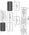
- Fig. 1 shows an example of a part of the radiological imaging method according to an embodiment of the invention, dealing with computing driving current intensity modulation of radiation source.
- the radiological imaging method includes a method to process the current intensity modulation of a radiation source along the vertical scanning direction.
- the figure 1 presents the functional block diagram of an example implementation using the salient points.
- Fig. 2 shows an example of a specific bones localization, here a patient full body including a spine continued by pelvis and leg, via salient points detection.
- the figure 2 presents a typical example of selected salient points on a lateral scout view.
- the succession of circles follows the patient spine in a globally vertical direction.
- This succession of salient points SP is spotted on the lateral image of a patient body.
- This patient body lateral image is plotted with respect to altitude Z (height along vertical scanning direction) as a function of the patient width, patient thickness th being perpendicular to plan of figure, both altitude and width w being expressed in mm.
- Fig. 3 shows an example of a corresponding parameter P which is a median signal patch value as a function of the vertical position Z along the height of the patient expressed in millimeters.
- the figure 3 presents the corresponding fully sampled signal profile along the vertical scanning of the patient.
- the selected salient points are indicated in figure 2 on the lateral scout view by circular dots which represent the circular patch which is around 5 cm diameter.
- Fig. 4 shows an example of a corresponding thickness profile th expressed in millimeters as a function of the vertical position Z along the height of the patient expressed in millimeters.
- the figure 4 presents the characteristic thickness determination on the lateral profile presented in the figure 2 .
- the patient thickness profile is plotted on figure 4 .
- the patient thickness th expressed in mm, is represented as a function of the vertical position Z, also expressed in mm.
- the figures 5 and 6 present a simulation of the standard relation of the voltage (kV) and current (mA) according to the equivalent PMMA thickness for the full spine protocol in "Flex Dose" mode, for the characteristic thicknesses 225 mm in frontal and 335 mm in lateral measured for the anthropomorphic phantom of the figures 15 , 16 and 17 taken as an example.
- Fig. 5 shows an example of constant voltages V expressed in kilovolts as a function of a patient equivalent thickness th expressed in centimeters, respectively for the frontal image and for the lateral image. These constant voltages can be chosen dependent on the characteristic thicknesses measures in the frontal and lateral scout views.
- voltage constant value has been selected at 90 kV (corresponding to a characteristic thickness of 225 mm measured in the frontal scout view of the anthropomorphic phantom) and is independent on the characteristic patient thicknesses ranging from about 10cm to about 50cm.
- voltage constant value has been selected at 120 kV (corresponding to a characteristic thickness of 335 mm measured in the frontal scout view of the anthropomorphic phantom) and is independent on the characteristic patient thicknesses ranging from about 10cm to about 50cm.
- Fig. 6 shows an example of a current modulation I expressed in milliamps as a function of a patient equivalent thickness th expressed in centimeters, respectively for the frontal image and for the lateral image.
- Fig. 7 shows an example of obtained numbers S of X-ray photons per detector pixel (representative of signal to noise ratios) as a function of a patient equivalent thickness th expressed in centimeters respectively for the frontal image and for the lateral image.
- the number of X-ray photons per detector pixel is rather constant at about 60, for equivalent patient thicknesses ranging from about 15cm to about 30cm, and then decreases abruptly from about 60 to about 5, for equivalent patient thicknesses ranging from about 30cm to about 40cm, and continues to decrease more softly to tend toward zero, without reaching actually zero, from about 40cm to about 50cm. Below 15cm, between 15cm and 10cm, this number increases abruptly to about 140.
- the number of X-ray photons per detector pixel is rather constant at about 27, for equivalent patient thicknesses ranging from about 20cm to about 37cm, and then decreases softly to tend toward zero, without reaching actually zero, for equivalent patient thicknesses ranging from about 40cm to about 50cm.. Below 20cm, between 20cm and 10cm, this number increases abruptly to about 250.
- Fig. 8 shows an example of radiation dose D received by patient in ⁇ Gy, as a function of a patient equivalent thickness th expressed in centimeters respectively for the frontal image and for the lateral image.
- the radiation dose received by patient increases first slowly from about none to about 100 micrograys, for equivalent patient thicknesses ranging from about 10cm to about 20cm, then increases much more abruptly from about 100 micrograys to about 850 micrograys, for equivalent patient thicknesses ranging from about 20cm to about 30cm, and afterwards remains roughly constant at about 850 micrograys, for equivalent patient thicknesses ranging from about 30cm to about 50cm.
- the radiation dose received by patient increases first slowly from about none to about 130 micrograys, for equivalent patient thicknesses ranging from about 10cm to about 25cm, then increases much more abruptly from about 130 micrograys to about 1700 micrograys, for equivalent patient thicknesses ranging from about 25cm to about 37cm, and afterwards remains roughly constant at about 1700 micrograys, for equivalent patient thicknesses ranging from about 37cm to about 50cm.
- L curve increases more slowly than F curve in first phase of slow increase, but then L curve increases more rapidly than F curve in second phase of abrupt (or quick) increase.
- the scale along horizontal and vertical axis are in mm, after scout view image has been binned (which means each zone of 20x20 original square pixels has been gathered in a new pixel), for scout view, frontal and lateral images taken after scout view having no such binning.
- Fig.9 to Fig. 12 show frontal and lateral images using a step of salient points detection, both before and after filtering in order to focus on the patient spine (or on the patient spine continued by one of his or her leg) and to exclude other bones, in order to enhance image contrast on the zone of interest which is here the patient spine.
- This filtering step aims at selecting only salient points which are located most probably on axial skeleton, here on spine and on one leg continuing the spine.
- Fig. 9 shows an example of a filtered frontal scout view, after salient points detection step, but before salient points filtering step.
- This patient body image is plotted with respect to altitude Z (height along vertical scanning direction) as a function of the patient width, patient thickness th being perpendicular to plan of figure, both altitude and width w being expressed in mm.
- Fig. 10 shows an example of a filtered frontal scout view, after salient points detection step and after salient points filtering step.
- This patient body image is plotted with respect to altitude Z (height along vertical scanning direction) as a function of the patient width, patient thickness th being perpendicular to plan of figure, both altitude and width w being expressed in mm.
- Bones 21 to 25 are spotted within patient 20.
- Patient 20 is plotted with respect to his or her height Z expressed in mm with respect to his or her width also expressed in mm.
- Rules for frontal image filtering step are the following ones:
- Fig. 11 shows an example of a filtered lateral scout view, after salient points detection step, but before salient points filtering step.
- This patient body image is plotted with respect to altitude Z (height along vertical scanning direction) as a function of the patient width, patient thickness th being perpendicular to plan of figure, both altitude and width w being expressed in mm.
- Fig. 12 shows an example of a filtered lateral scout view, after salient points detection step and after salient points filtering step.
- This patient body image is plotted with respect to altitude Z (height along vertical scanning direction) as a function of the patient width, patient thickness th being perpendicular to plan of figure, both altitude and width w being expressed in mm.
- Bones 31 to 35 are spotted within patient 30.
- Patient 30 is plotted with respect to his or her height Z expressed in mm and with respect to his or her width also expressed in mm.
- Rules for lateral image filtering step are the following ones:
- a specific image, either frontal or lateral, may also be corrected:
- a profile of driving current intensity modulation is calculated from the scout view.
- Fig. 13 shows an example of a filtered frontal scout view, after deep neural network detection step.
- This patient body image is plotted with respect to altitude Z (height along vertical scanning direction) as a function of the patient width, patient thickness th being perpendicular to plan of figure, both altitude and width w being expressed in mm.
- Fig. 14 shows an example of a filtered lateral scout view, after deep neural network detection step.
- This patient body image is plotted with respect to altitude Z (height along vertical scanning direction) as a function of the patient width, patient thickness th being perpendicular to plan of figure, both altitude and width w being expressed in mm.
- Fig. 15 shows an example of lateral image, of constant driving current intensity and of constant driving voltage intensity, in a constant current and voltage mode.
- the figure 15 presents the lateral scan of an anthropomorphic phantom in the case of the modulation is disabled.
- a patient 60 is represented on a lateral image.
- This patient body image is plotted with respect to altitude Z (height along vertical scanning direction) as a function of the patient width, patient thickness th being perpendicular to plan of figure, both altitude and width w being expressed in mm.
- There is a constant driving current intensity 61 all along the vertical scanning direction Z for example at about 350 mA.
- Patient 60 lateral image is of average quality.
- Fig. 16 shows an example of lateral image, of modulated driving current intensity and of constant driving voltage intensity, in a modulated current and constant voltage mode.
- the figure 16 presents the lateral scan of the anthropomorphic phantom in the case of the modulation is enabled but with a fixed voltage (kV).
- a patient 70 is represented on a lateral image.
- This patient body image is plotted with respect to altitude Z (height along vertical scanning direction) as a function of the patient width, patient thickness th being perpendicular to plan of figure, both altitude and width w being expressed in mm.
- There is a driving current intensity modulation 71 all along the vertical scanning direction Z for example varying between about 10 mA and about 350 mA.
- Patient 70 lateral image is of notably similar quality than patient 60 lateral image, but taken with a lower radiation dose and adjusted to get the right level of signal at each position along vertical scanning direction.
- the blank or void part of the image outside the patient is modulated correspondingly to the modulation profile applied.
- the image is then corrected by the normalization with the excepted signal without attenuation to remove this modulation of the blank part in image, to avoid compromising the radiologist analysis of the image.
- the demodulated image follows then a standard contrast enhancement process before the presentation to the radiologist.
- Fig. 17 shows an example of final lateral image as displayed to the radiologist.
- the figure 17 presents for instance the lateral scan image acquired with current modulation only including the demodulation and contrast enhancement processing as it is presented to the radiologist.
- This final lateral image is of good quality.
Landscapes
- Health & Medical Sciences (AREA)
- Life Sciences & Earth Sciences (AREA)
- Engineering & Computer Science (AREA)
- Medical Informatics (AREA)
- Physics & Mathematics (AREA)
- Surgery (AREA)
- General Health & Medical Sciences (AREA)
- Nuclear Medicine, Radiotherapy & Molecular Imaging (AREA)
- Optics & Photonics (AREA)
- Pathology (AREA)
- Radiology & Medical Imaging (AREA)
- Biomedical Technology (AREA)
- Heart & Thoracic Surgery (AREA)
- Molecular Biology (AREA)
- Biophysics (AREA)
- Animal Behavior & Ethology (AREA)
- High Energy & Nuclear Physics (AREA)
- Public Health (AREA)
- Veterinary Medicine (AREA)
- Artificial Intelligence (AREA)
- Evolutionary Computation (AREA)
- Orthopedic Medicine & Surgery (AREA)
- Dentistry (AREA)
- Oral & Maxillofacial Surgery (AREA)
- Computer Vision & Pattern Recognition (AREA)
- Software Systems (AREA)
- General Physics & Mathematics (AREA)
- Automation & Control Theory (AREA)
- Apparatus For Radiation Diagnosis (AREA)
Claims (18)
- Procédé d'imagerie radiologique comprenant :> 2 sources de rayonnement ayant des directions d'imagerie orthogonales entre elles, une source de rayonnement frontal et une source de rayonnement latéral, coulissant verticalement de manière à réaliser un balayage vertical d'un patient debout (20) le long d'une direction de balayage vertical (Z),dans lequel ledit procédé radiologique comprend au moins un mode de fonctionnement dans lequel :> une vue de reconnaissance frontale est réalisée en réalisant (1) un balayage vertical préliminaire d'un patient debout (20) le long de ladite direction de balayage vertical (Z) par ladite source de rayonnement frontal,> ladite vue de reconnaissance frontale est traitée (2, 3) pour identifier une localisation spécifique d'un ou plusieurs os (21) dans ladite vue de reconnaissance frontale,> une intensité de courant d'entraînement (11) d'au moins ladite source de rayonnement frontal est modulée le long de ladite direction de balayage vertical (Z), en fonction de l'épaisseur du patient et de ladite localisation spécifique d'un ou plusieurs os identifiée (21) le long de ladite direction de balayage vertical (Z),> sans aucune modulation d'intensité de tension d'entraînement (11) de ladite source de rayonnement frontal le long de ladite direction de balayage vertical (Z),> ladite modulation d'intensité de courant d'entraînement (11) de ladite source de rayonnement frontal est réalisée automatiquement, de manière à améliorer un compromis entre :o une diminution de la dose globale de rayonnement reçue par un patient (20) lors dudit balayage vertical,o tout en maintenant à un niveau suffisant les contrastes d'image locaux de ladite localisation spécifique d'un ou plusieurs os identifiée (21) à différentes positions d'imagerie le long de ladite direction de balayage vertical (Z), pour l'image frontale.
- Procédé d'imagerie radiologique comprenant :> 2 sources de rayonnement ayant des directions d'imagerie orthogonales entre elles, une source de rayonnement frontal et une source de rayonnement latéral, coulissant verticalement de manière à réaliser un balayage vertical d'un patient debout (30) le long d'une direction de balayage vertical (Z),dans lequel ledit procédé radiologique comprend au moins un mode de fonctionnement dans lequel :> une vue de reconnaissance latérale est réalisée en réalisant (1) un balayage vertical préliminaire d'un patient debout (30) le long de ladite direction de balayage vertical (Z) par ladite source de rayonnement latéral,> ladite vue de reconnaissance latérale est traitée (2, 3) pour identifier une localisation spécifique d'un ou plusieurs os (31) dans ladite vue de reconnaissance latérale,> une intensité de courant d'entraînement (11) d'au moins ladite source de rayonnement latéral est modulée le long de ladite direction de balayage vertical (Z), en fonction de l'épaisseur du patient et de ladite localisation spécifique d'un ou plusieurs os identifiée (31) le long de ladite direction de balayage vertical (Z),> sans aucune modulation d'intensité de tension d'entraînement de ladite source de rayonnement latéral le long de ladite direction de balayage vertical (Z),> ladite modulation d'intensité de courant d'entraînement de ladite source de rayonnement latéral est réalisée automatiquement, de manière à améliorer un compromis entre :o une diminution de la dose globale de rayonnement reçue par un patient (30) lors dudit balayage vertical,o tout en maintenant à un niveau suffisant les contrastes d'image locaux de ladite localisation spécifique d'un ou plusieurs os identifiée (31) à différentes positions d'imagerie le long de ladite direction de balayage vertical (Z), pour l'image latérale.
- Procédé d'imagerie radiologique comprenant :> 2 sources de rayonnement ayant des directions d'imagerie orthogonales entre elles, une source de rayonnement frontal et une source de rayonnement latéral, coulissant verticalement de manière à réaliser un balayage vertical d'un patient debout (20, 30) le long d'une direction de balayage vertical (Z),dans lequel ledit procédé radiologique comprend au moins un mode de fonctionnement dans lequel :> des vues de reconnaissance frontale et latérale sont réalisées en réalisant (1) un balayage vertical préliminaire d'un patient debout le long de ladite direction de balayage vertical par lesdites sources de rayonnement frontal et latéral,> lesdites vues de reconnaissance frontale et latérale sont traitées (2, 3) pour identifier une localisation spécifique d'un ou plusieurs os (21, 31) dans lesdites deux vues de reconnaissance frontale et latérale,> des intensités de courant d'entraînement (11) desdites deux sources de rayonnement frontal et latéral sont modulées le long de ladite direction de balayage vertical, en fonction de l'épaisseur du patient et de ladite localisation spécifique d'un ou plusieurs os identifiée (21, 31) le long de ladite direction de balayage vertical (Z),> sans aucune modulation d'intensités de tension d'entraînement (11) de l'une des sources de rayonnement frontal ou latéral le long de ladite direction de balayage vertical (Z),> ladite modulation d'intensité de courant d'entraînement de ladite source de rayonnement frontal, ainsi que ladite modulation d'intensité de courant d'entraînement de ladite source de rayonnement latéral, sont toutes réalisées simultanément, de préférence de manière synchrone, et automatiquement, de manière à améliorer un compromis entre :∘ une diminution de la dose globale de rayonnement reçue par un patient (20, 30) lors dudit balayage vertical,∘ tout en maintenant à un niveau suffisant les contrastes d'image locaux de ladite localisation spécifique d'un ou plusieurs os identifiée (21, 31) à différentes positions d'imagerie le long de ladite direction de balayage vertical (Z), pour l'image frontale et pour l'image latérale.
- Procédé d'imagerie radiologique selon l'une quelconque des revendications précédentes, dans lequel ladite ou lesdites modulations d'intensité de courant d'entraînement (11) de ladite source de rayonnement frontal est ou sont également réalisées de manière à atteindre une valeur de rapport signal sur bruit qui est constante et commune à la plupart desdites positions d'imagerie le long de ladite direction de balayage vertical (Z), de préférence à toutes lesdites positions d'imagerie le long de ladite direction de balayage vertical (Z), pour ladite image frontale et/ou pour ladite image latérale, mais qui peut prendre respectivement deux valeurs différentes pour l'image frontale et pour l'image latérale,
et de préférence dans lequel, pour chacune desdites images frontale et/ou latérale, ladite valeur de rapport signal sur bruit est constante et prédéterminée pour chaque organe différent du patient (20, 30) à imager. - Procédé d'imagerie radiologique selon la revendication 4, dans lequel :> pour une image frontale de la colonne vertébrale d'un patient, ladite valeur standard de rapport signal sur bruit correspond à un nombre de photons radiographiques reçus par pixel détecteur compris entre 50 et 70, l'opérateur du procédé d'imagerie radiologique ayant de préférence la possibilité de s'écarter, via une instruction manuelle, de cette valeur standard d'au moins + ou - 20 %, de préférence d'au moins + ou - 50 %,> et/ou pour une image frontale de la colonne vertébrale d'un patient, ladite valeur standard de rapport signal sur bruit correspond à un nombre de photons radiographiques reçus par pixel détecteur compris entre 20 et 40, l'opérateur du procédé d'imagerie radiologique ayant de préférence la possibilité de s'écarter, via une instruction manuelle, de cette valeur standard d'au moins + ou - 20 %, de préférence d'au moins + ou - 50 %.
- Procédé d'imagerie radiologique selon l'une quelconque des revendications précédentes, dans lequel ladite image frontale et/ou latérale, après avoir subi au moins une première étape de modulation d'intensité de courant, est normalisée par homogénéisation de régions situées juste à l'extérieur de contours du corps du patient, afin de se débarrasser d'artefacts d'image provenant de ladite modulation d'intensité de courant d'entraînement (11),
et de préférence dans lequel ladite image frontale et/ou latérale, après avoir été normalisée, subit une étape d'amélioration de contraste. - Procédé d'imagerie radiologique selon l'une quelconque des revendications précédentes, dans lequel ladite localisation spécifique d'un ou plusieurs os identifiée (21, 31) exclut des parties métalliques éventuelles, comme par exemple une prothèse métallique d'une partie du squelette du corps du patient ou comme par exemple des protections métalliques mis en place sur le corps du patient avant de réaliser ledit procédé d'imagerie radiologique.
- Procédé d'imagerie radiologique selon l'une quelconque des revendications précédentes, dans lequel ladite modulation d'intensité de courant (11) est maximisée de manière à maximiser également ladite vitesse de balayage vertical à une valeur constante.
- Procédé d'imagerie radiologique selon l'une quelconque des revendications précédentes, dans lequel ledit taux de modulation(s) d'intensité de courant ne dépasse pas un seuil prédéterminé de 5 mA par milliseconde, de préférence un seuil prédéterminé de 2 mA par milliseconde, plus préférablement un seuil prédéterminé de 1 mA par milliseconde.
- Procédé d'imagerie radiologique selon l'une quelconque des revendications précédentes, dans lequel ladite ou lesdites modulations d'intensité de courant est ou sont dans la plage d'au moins 20 mA à 300 mA, et de préférence de 10 mA à 400 mA.
- Procédé d'imagerie radiologique selon l'une quelconque des revendications précédentes, dans lequel ladite intensité de tension fixe est sélectionnée dans une plage allant de 50 kV à 120 kV.
- Procédé d'imagerie radiologique selon l'une quelconque des revendications précédentes, dans lequel ladite vitesse de balayage vertical est dans la plage d'au moins 8 cm/seconde à 20 cm/seconde, et de préférence de 4 cm/seconde à 30 cm/seconde.
- Procédé d'imagerie radiologique selon l'une quelconque des revendications précédentes, dans lequel chacune de ladite ou desdites vues de reconnaissance frontale et/ou latérale est réalisée en réalisant un balayage vertical préliminaire (1) d'un patient debout (20, 30) le long d'une direction de balayage vertical (Z) avec une dose globale de rayonnement réduite par comparaison à chacune desdites images frontale et latérale, avant de réaliser chacune desdites images frontale et latérale,
et de préférence dans lequel ledit rayonnement global réduit est inférieur à 10 % de ladite dose globale de rayonnement, de préférence inférieure à 5 % de ladite dose globale de rayonnement. - Procédé d'imagerie radiologique selon l'une quelconque des revendications précédentes, dans lequel des pixels de ladite vue de reconnaissance sont rassemblés (2), de préférence par zones de NxN pixels, plus préférablement par zones d'au moins 10x10 pixels, pour réaliser des zones imagées.
- Procédé d'imagerie radiologique selon l'une quelconque des revendications précédentes, dans lequel lesdites images ou lesdites zones imagées sont traitées (3) pour identifier des points saillants qui à leur tour sont utilisés pour calculer ledit profil d'épaisseur et pour identifier ladite localisation spécifique d'un ou plusieurs os (21, 31) d'un patient debout (20, 30) le long de ladite direction de balayage vertical (Z), ou dans lequel lesdites images ou lesdites zones imagées sont traitées par un réseau neuronal pour calculer ledit profil d'épaisseur et identifier ladite localisation spécifique d'un ou plusieurs os (21, 31) d'un patient debout (20, 30) le long de ladite direction de balayage vertical (Z).
- Procédé d'imagerie radiologique selon l'une quelconque des revendications précédentes, dans lequel lesdites 2 sources de rayonnement coulissent verticalement de manière à réaliser un balayage vertical d'un bassin ou d'un rachis ou d'une colonne vertébrale ou d'un corps complet d'un patient debout (20, 30) le long d'une direction de balayage verticale (Z).
- Procédé d'imagerie radiologique selon l'une quelconque des revendications précédentes, dans lequel 2 détecteurs de rayonnement sont respectivement associés auxdites 2 sources de rayonnements, lesdits 2 détecteurs de rayonnement étant 2 détecteurs de comptage de photons (PCD) chacun étant associé à une fonction de traitement automatique d'image équilibrant automatiquement une densité d'image quelle que soit la dose de rayonnement reçue sur la surface sensible dudit détecteur de rayonnement pour améliorer un contraste d'image.
- Procédé d'imagerie radiologique selon l'une quelconque des revendications précédentes, dans lequel 2 détecteurs de rayonnement sont respectivement associés auxdites 2 sources de rayonnements, lesdits 2 détecteurs de rayonnement étant 2 détecteurs de comptage multi-énergie, de préférence étant 2 détecteur de comptage de photons résolus en énergie (ERPCD).
Applications Claiming Priority (2)
| Application Number | Priority Date | Filing Date | Title |
|---|---|---|---|
| PCT/IB2019/001291 WO2021094806A1 (fr) | 2019-11-14 | 2019-11-14 | Procédé d'imagerie radiologique |
| PCT/EP2020/070058 WO2021094004A1 (fr) | 2019-11-14 | 2020-07-15 | Procédé d'imagerie radiologique |
Publications (3)
| Publication Number | Publication Date |
|---|---|
| EP4057905A1 EP4057905A1 (fr) | 2022-09-21 |
| EP4057905B1 true EP4057905B1 (fr) | 2023-11-22 |
| EP4057905C0 EP4057905C0 (fr) | 2023-11-22 |
Family
ID=69185621
Family Applications (2)
| Application Number | Title | Priority Date | Filing Date |
|---|---|---|---|
| EP19839657.4A Active EP4057904B1 (fr) | 2019-11-14 | 2019-11-14 | Méthode d'imagerie radiologique |
| EP20739695.3A Active EP4057905B1 (fr) | 2019-11-14 | 2020-07-15 | Procédé d'imagerie radiologique |
Family Applications Before (1)
| Application Number | Title | Priority Date | Filing Date |
|---|---|---|---|
| EP19839657.4A Active EP4057904B1 (fr) | 2019-11-14 | 2019-11-14 | Méthode d'imagerie radiologique |
Country Status (6)
| Country | Link |
|---|---|
| US (2) | US12207959B2 (fr) |
| EP (2) | EP4057904B1 (fr) |
| JP (2) | JP7345653B2 (fr) |
| CN (2) | CN114929111B (fr) |
| GB (2) | GB2604553B (fr) |
| WO (2) | WO2021094806A1 (fr) |
Families Citing this family (5)
| Publication number | Priority date | Publication date | Assignee | Title |
|---|---|---|---|---|
| GB2604553B (en) * | 2019-11-14 | 2023-08-02 | Eos Imaging | Radiological imaging method |
| EP4201335A1 (fr) * | 2021-12-21 | 2023-06-28 | Koninklijke Philips N.V. | Système d'imagerie spectrale ct à rayons x |
| US20250302407A1 (en) | 2022-05-18 | 2025-10-02 | Eos Imaging | Radiological imaging method with a multi-energy scout view |
| JP2025515933A (ja) * | 2022-05-18 | 2025-05-20 | イオス・イメージング | 多重エネルギースキャン画像を用いる放射線撮像方法 |
| CN115128373B (zh) * | 2022-06-08 | 2025-08-01 | 浙江大学 | 一种主动学习的辐射源快速近场扫描方法 |
Family Cites Families (32)
| Publication number | Priority date | Publication date | Assignee | Title |
|---|---|---|---|---|
| US5450462A (en) | 1993-11-19 | 1995-09-12 | General Electric Company | Modulation of x-ray tube current during CT scanning with modulation limit |
| JPH1021372A (ja) * | 1996-07-05 | 1998-01-23 | Toshiba Corp | X線ct装置 |
| JP4463960B2 (ja) | 2000-09-28 | 2010-05-19 | ジーイー・メディカル・システムズ・グローバル・テクノロジー・カンパニー・エルエルシー | X線ctシステムおよび操作コンソール、それらの制御方法ならびに記憶媒体 |
| JP4532005B2 (ja) | 2001-03-09 | 2010-08-25 | 株式会社日立メディコ | X線ct装置及びその画像表示方法 |
| US7177453B2 (en) | 2002-11-26 | 2007-02-13 | General Electric Company | Method and apparatus for partitioning a volume |
| FR2856170B1 (fr) | 2003-06-10 | 2005-08-26 | Biospace Instr | Procede d'imagerie radiographique pour la reconstruction tridimensionnelle, dispositif et programme d'ordinateur pour mettre en oeuvre ce procede |
| KR100967950B1 (ko) * | 2007-05-03 | 2010-07-06 | 목포과학대학산학협력단 | 씨티 시뮬레이션 장치 및 방법, 그것을 기록한 기록매체와프로그램 |
| JP2010213799A (ja) * | 2009-03-13 | 2010-09-30 | Toshiba Corp | X線画像診断装置及び画像処理装置 |
| US8031831B2 (en) | 2009-05-28 | 2011-10-04 | Kabushiki Kaisha Toshiba | Voltage and or current modulation in dual energy computed tomography |
| US8155263B2 (en) | 2009-07-31 | 2012-04-10 | General Electric Company | Apparatus and method for voltage modulation in X-ray computed tomography |
| CN102397080B (zh) * | 2010-09-19 | 2014-01-22 | 上海西门子医疗器械有限公司 | X射线计算机断层摄影系统和方法 |
| EP3524159B1 (fr) * | 2010-12-08 | 2021-01-20 | Bayer Healthcare LLC | Génération d'un modèle approprié d'estimation de la dose de rayonnement reçue par un patient lors de procédures d'imagerie médicale |
| JP2013056031A (ja) * | 2011-09-08 | 2013-03-28 | Fujifilm Corp | 撮影条件決定支援装置及び撮影条件決定支援方法 |
| CN104997528B (zh) * | 2014-04-21 | 2018-03-27 | 东芝医疗系统株式会社 | X 射线计算机断层拍摄装置以及拍摄条件设定辅助装置 |
| JP6466079B2 (ja) | 2014-04-21 | 2019-02-06 | キヤノンメディカルシステムズ株式会社 | X線コンピュータ断層撮影装置及びスキャン計画設定支援装置 |
| CN104068456B (zh) | 2014-07-02 | 2016-08-24 | 江苏牧羊控股有限公司 | 一种颗粒仓与齿轮箱的连接装置 |
| US10213172B2 (en) * | 2015-02-20 | 2019-02-26 | General Electric Company | Imaging method and system of tube voltage and current optimization |
| US9962134B2 (en) * | 2015-10-28 | 2018-05-08 | Medtronic Navigation, Inc. | Apparatus and method for maintaining image quality while minimizing X-ray dosage of a patient |
| WO2017137792A1 (fr) * | 2016-02-10 | 2017-08-17 | Eos Imaging | Procédé de radiographie d'un organe d'un patient |
| JP6906905B2 (ja) * | 2016-06-29 | 2021-07-21 | キヤノンメディカルシステムズ株式会社 | X線診断装置 |
| US10660190B2 (en) | 2017-02-06 | 2020-05-19 | Canon Medical Systems Corporation | X-ray computed tomography apparatus |
| JP6745755B2 (ja) * | 2017-05-18 | 2020-08-26 | 富士フイルム株式会社 | 放射線画像撮影システム、放射線画像撮影方法、放射線画像撮影プログラム、及び体厚推定装置 |
| WO2018224039A1 (fr) * | 2017-06-08 | 2018-12-13 | Shenzhen United Imaging Healthcare Co., Ltd. | Systèmes et procédés d'imagerie médicale |
| EP3871607B1 (fr) * | 2017-07-04 | 2023-07-26 | EOS Imaging | Procédé de radiographie d'un organe d'un patient |
| US10702219B2 (en) | 2017-09-15 | 2020-07-07 | General Electric Company | Methods, systems, and apparatus for determining radiation doses |
| US10973489B2 (en) | 2017-09-29 | 2021-04-13 | General Electric Company | CT imaging system and method using a task-based image quality metric to achieve a desired image quality |
| US10582905B2 (en) * | 2018-02-09 | 2020-03-10 | General Electric Company | Systems and method for x-ray imaging |
| JP6925294B2 (ja) * | 2018-03-23 | 2021-08-25 | 富士フイルム株式会社 | 画像処理装置、放射線画像撮影システム、画像処理方法、及び画像処理プログラム |
| CN109060849B (zh) * | 2018-06-29 | 2021-04-27 | 上海联影医疗科技股份有限公司 | 一种确定辐射剂量调制线的方法、系统和装置 |
| CN109077746B (zh) * | 2018-06-29 | 2022-08-02 | 上海联影医疗科技股份有限公司 | 一种确定辐射剂量调制线的方法、系统和装置 |
| CN109276266A (zh) * | 2018-09-19 | 2019-01-29 | 晓智科技(成都)有限公司 | 一种根据厚度值进行x光成像剂量确定方法 |
| GB2604553B (en) * | 2019-11-14 | 2023-08-02 | Eos Imaging | Radiological imaging method |
-
2019
- 2019-11-14 GB GB2208712.6A patent/GB2604553B/en active Active
- 2019-11-14 EP EP19839657.4A patent/EP4057904B1/fr active Active
- 2019-11-14 WO PCT/IB2019/001291 patent/WO2021094806A1/fr not_active Ceased
- 2019-11-14 JP JP2022528120A patent/JP7345653B2/ja active Active
- 2019-11-14 US US17/776,031 patent/US12207959B2/en active Active
- 2019-11-14 CN CN201980103432.6A patent/CN114929111B/zh active Active
-
2020
- 2020-07-15 US US17/776,022 patent/US12161492B2/en active Active
- 2020-07-15 CN CN202080085548.4A patent/CN114786583B/zh active Active
- 2020-07-15 JP JP2022528116A patent/JP7617915B2/ja active Active
- 2020-07-15 GB GB2206990.0A patent/GB2605047B/en active Active
- 2020-07-15 EP EP20739695.3A patent/EP4057905B1/fr active Active
- 2020-07-15 WO PCT/EP2020/070058 patent/WO2021094004A1/fr not_active Ceased
Also Published As
| Publication number | Publication date |
|---|---|
| EP4057904A1 (fr) | 2022-09-21 |
| EP4057904B1 (fr) | 2025-06-11 |
| EP4057905A1 (fr) | 2022-09-21 |
| JP7617915B2 (ja) | 2025-01-20 |
| GB2604553B (en) | 2023-08-02 |
| GB2604553A (en) | 2022-09-07 |
| JP2023501672A (ja) | 2023-01-18 |
| CN114786583A (zh) | 2022-07-22 |
| WO2021094004A1 (fr) | 2021-05-20 |
| US20220386972A1 (en) | 2022-12-08 |
| US20220386973A1 (en) | 2022-12-08 |
| GB2605047A (en) | 2022-09-21 |
| GB2605047B (en) | 2024-10-30 |
| GB202206990D0 (en) | 2022-06-29 |
| CN114929111A (zh) | 2022-08-19 |
| JP2023501675A (ja) | 2023-01-18 |
| JP7345653B2 (ja) | 2023-09-15 |
| US12207959B2 (en) | 2025-01-28 |
| CN114786583B (zh) | 2025-07-25 |
| US12161492B2 (en) | 2024-12-10 |
| EP4057905C0 (fr) | 2023-11-22 |
| GB202208712D0 (en) | 2022-07-27 |
| CN114929111B (zh) | 2026-01-02 |
| EP4057904C0 (fr) | 2025-06-11 |
| WO2021094806A1 (fr) | 2021-05-20 |
Similar Documents
| Publication | Publication Date | Title |
|---|---|---|
| EP4057905B1 (fr) | Procédé d'imagerie radiologique | |
| EP1216661B1 (fr) | Procédé et appareil de diagnostic médical pour le contrôle de techniques d'exposition à deux spectres d'énergie basées sur des informations d'images | |
| US7983383B2 (en) | X-ray CT apparatus | |
| WO2010038536A1 (fr) | Tomodensitomètre à rayons x | |
| JP2010125334A (ja) | 二重エネルギ計算機式断層写真法を用いた多種物質分解 | |
| US7239730B2 (en) | Method and apparatus for volume scoring calcification concentrations of a CT scan | |
| JP2003070780A (ja) | コンピュータトモグラフによる測定データの取得方法およびコンピュータトモグラフ | |
| US6983180B2 (en) | Method of determining and displaying a helical artifact index | |
| US20030048873A1 (en) | Method for improving a radiological examination and device therefor | |
| US6108403A (en) | X-ray equalization filter | |
| EP4525724A1 (fr) | Méthode d'imagerie radiologique avec image de scannogramme à plusieurs niveaux d'énergie | |
| CN117437144A (zh) | 用于图像去噪的方法和系统 | |
| US20260069234A1 (en) | Method and apparatus for performing automatic exposure control in ct imaging systems | |
| US20250302408A1 (en) | Radiological imaging method with a multi-energy scan image | |
| CN120182614A (zh) | 一种医学图像数据去噪模型的生成方法、去噪方法以及电子设备 | |
| Xu et al. | Arbitrary shape region-of-interest fluoroscopy system | |
| DE102006056985A1 (de) | Adaptive Bildverarbeitung und -wiedergabe für digitale und Computertomographiebilder |
Legal Events
| Date | Code | Title | Description |
|---|---|---|---|
| STAA | Information on the status of an ep patent application or granted ep patent |
Free format text: STATUS: UNKNOWN |
|
| STAA | Information on the status of an ep patent application or granted ep patent |
Free format text: STATUS: THE INTERNATIONAL PUBLICATION HAS BEEN MADE |
|
| PUAI | Public reference made under article 153(3) epc to a published international application that has entered the european phase |
Free format text: ORIGINAL CODE: 0009012 |
|
| STAA | Information on the status of an ep patent application or granted ep patent |
Free format text: STATUS: REQUEST FOR EXAMINATION WAS MADE |
|
| 17P | Request for examination filed |
Effective date: 20220519 |
|
| AK | Designated contracting states |
Kind code of ref document: A1 Designated state(s): AL AT BE BG CH CY CZ DE DK EE ES FI FR GB GR HR HU IE IS IT LI LT LU LV MC MK MT NL NO PL PT RO RS SE SI SK SM TR |
|
| DAV | Request for validation of the european patent (deleted) | ||
| DAX | Request for extension of the european patent (deleted) | ||
| GRAP | Despatch of communication of intention to grant a patent |
Free format text: ORIGINAL CODE: EPIDOSNIGR1 |
|
| STAA | Information on the status of an ep patent application or granted ep patent |
Free format text: STATUS: GRANT OF PATENT IS INTENDED |
|
| INTG | Intention to grant announced |
Effective date: 20230609 |
|
| GRAS | Grant fee paid |
Free format text: ORIGINAL CODE: EPIDOSNIGR3 |
|
| GRAA | (expected) grant |
Free format text: ORIGINAL CODE: 0009210 |
|
| STAA | Information on the status of an ep patent application or granted ep patent |
Free format text: STATUS: THE PATENT HAS BEEN GRANTED |
|
| AK | Designated contracting states |
Kind code of ref document: B1 Designated state(s): AL AT BE BG CH CY CZ DE DK EE ES FI FR GB GR HR HU IE IS IT LI LT LU LV MC MK MT NL NO PL PT RO RS SE SI SK SM TR |
|
| REG | Reference to a national code |
Ref country code: GB Ref legal event code: FG4D |
|
| REG | Reference to a national code |
Ref country code: CH Ref legal event code: EP Ref country code: DE Ref legal event code: R096 Ref document number: 602020021516 Country of ref document: DE |
|
| REG | Reference to a national code |
Ref country code: IE Ref legal event code: FG4D |
|
| U01 | Request for unitary effect filed |
Effective date: 20231211 |
|
| U07 | Unitary effect registered |
Designated state(s): AT BE BG DE DK EE FI FR IT LT LU LV MT NL PT SE SI Effective date: 20231221 |
|
| PG25 | Lapsed in a contracting state [announced via postgrant information from national office to epo] |
Ref country code: GR Free format text: LAPSE BECAUSE OF FAILURE TO SUBMIT A TRANSLATION OF THE DESCRIPTION OR TO PAY THE FEE WITHIN THE PRESCRIBED TIME-LIMIT Effective date: 20240223 |
|
| PG25 | Lapsed in a contracting state [announced via postgrant information from national office to epo] |
Ref country code: IS Free format text: LAPSE BECAUSE OF FAILURE TO SUBMIT A TRANSLATION OF THE DESCRIPTION OR TO PAY THE FEE WITHIN THE PRESCRIBED TIME-LIMIT Effective date: 20240322 |
|
| PG25 | Lapsed in a contracting state [announced via postgrant information from national office to epo] |
Ref country code: ES Free format text: LAPSE BECAUSE OF FAILURE TO SUBMIT A TRANSLATION OF THE DESCRIPTION OR TO PAY THE FEE WITHIN THE PRESCRIBED TIME-LIMIT Effective date: 20231122 |
|
| PG25 | Lapsed in a contracting state [announced via postgrant information from national office to epo] |
Ref country code: IS Free format text: LAPSE BECAUSE OF FAILURE TO SUBMIT A TRANSLATION OF THE DESCRIPTION OR TO PAY THE FEE WITHIN THE PRESCRIBED TIME-LIMIT Effective date: 20240322 Ref country code: GR Free format text: LAPSE BECAUSE OF FAILURE TO SUBMIT A TRANSLATION OF THE DESCRIPTION OR TO PAY THE FEE WITHIN THE PRESCRIBED TIME-LIMIT Effective date: 20240223 Ref country code: ES Free format text: LAPSE BECAUSE OF FAILURE TO SUBMIT A TRANSLATION OF THE DESCRIPTION OR TO PAY THE FEE WITHIN THE PRESCRIBED TIME-LIMIT Effective date: 20231122 |
|
| PG25 | Lapsed in a contracting state [announced via postgrant information from national office to epo] |
Ref country code: RS Free format text: LAPSE BECAUSE OF FAILURE TO SUBMIT A TRANSLATION OF THE DESCRIPTION OR TO PAY THE FEE WITHIN THE PRESCRIBED TIME-LIMIT Effective date: 20231122 Ref country code: PL Free format text: LAPSE BECAUSE OF FAILURE TO SUBMIT A TRANSLATION OF THE DESCRIPTION OR TO PAY THE FEE WITHIN THE PRESCRIBED TIME-LIMIT Effective date: 20231122 Ref country code: NO Free format text: LAPSE BECAUSE OF FAILURE TO SUBMIT A TRANSLATION OF THE DESCRIPTION OR TO PAY THE FEE WITHIN THE PRESCRIBED TIME-LIMIT Effective date: 20240222 Ref country code: HR Free format text: LAPSE BECAUSE OF FAILURE TO SUBMIT A TRANSLATION OF THE DESCRIPTION OR TO PAY THE FEE WITHIN THE PRESCRIBED TIME-LIMIT Effective date: 20231122 |
|
| PG25 | Lapsed in a contracting state [announced via postgrant information from national office to epo] |
Ref country code: CZ Free format text: LAPSE BECAUSE OF FAILURE TO SUBMIT A TRANSLATION OF THE DESCRIPTION OR TO PAY THE FEE WITHIN THE PRESCRIBED TIME-LIMIT Effective date: 20231122 |
|
| PG25 | Lapsed in a contracting state [announced via postgrant information from national office to epo] |
Ref country code: SK Free format text: LAPSE BECAUSE OF FAILURE TO SUBMIT A TRANSLATION OF THE DESCRIPTION OR TO PAY THE FEE WITHIN THE PRESCRIBED TIME-LIMIT Effective date: 20231122 |
|
| PG25 | Lapsed in a contracting state [announced via postgrant information from national office to epo] |
Ref country code: SM Free format text: LAPSE BECAUSE OF FAILURE TO SUBMIT A TRANSLATION OF THE DESCRIPTION OR TO PAY THE FEE WITHIN THE PRESCRIBED TIME-LIMIT Effective date: 20231122 Ref country code: SK Free format text: LAPSE BECAUSE OF FAILURE TO SUBMIT A TRANSLATION OF THE DESCRIPTION OR TO PAY THE FEE WITHIN THE PRESCRIBED TIME-LIMIT Effective date: 20231122 Ref country code: RO Free format text: LAPSE BECAUSE OF FAILURE TO SUBMIT A TRANSLATION OF THE DESCRIPTION OR TO PAY THE FEE WITHIN THE PRESCRIBED TIME-LIMIT Effective date: 20231122 Ref country code: CZ Free format text: LAPSE BECAUSE OF FAILURE TO SUBMIT A TRANSLATION OF THE DESCRIPTION OR TO PAY THE FEE WITHIN THE PRESCRIBED TIME-LIMIT Effective date: 20231122 |
|
| U20 | Renewal fee for the european patent with unitary effect paid |
Year of fee payment: 5 Effective date: 20240621 |
|
| RAP4 | Party data changed (patent owner data changed or rights of a patent transferred) |
Owner name: EOS IMAGING |
|
| U1H | Name or address of the proprietor changed after the registration of the unitary effect |
Owner name: EOS IMAGING; FR |
|
| REG | Reference to a national code |
Ref country code: DE Ref legal event code: R097 Ref document number: 602020021516 Country of ref document: DE |
|
| PLBE | No opposition filed within time limit |
Free format text: ORIGINAL CODE: 0009261 |
|
| STAA | Information on the status of an ep patent application or granted ep patent |
Free format text: STATUS: NO OPPOSITION FILED WITHIN TIME LIMIT |
|
| 26N | No opposition filed |
Effective date: 20240823 |
|
| PG25 | Lapsed in a contracting state [announced via postgrant information from national office to epo] |
Ref country code: MC Free format text: LAPSE BECAUSE OF FAILURE TO SUBMIT A TRANSLATION OF THE DESCRIPTION OR TO PAY THE FEE WITHIN THE PRESCRIBED TIME-LIMIT Effective date: 20231122 |
|
| REG | Reference to a national code |
Ref country code: CH Ref legal event code: PL |
|
| PG25 | Lapsed in a contracting state [announced via postgrant information from national office to epo] |
Ref country code: CH Free format text: LAPSE BECAUSE OF NON-PAYMENT OF DUE FEES Effective date: 20240731 |
|
| PG25 | Lapsed in a contracting state [announced via postgrant information from national office to epo] |
Ref country code: IE Free format text: LAPSE BECAUSE OF NON-PAYMENT OF DUE FEES Effective date: 20240715 |
|
| U20 | Renewal fee for the european patent with unitary effect paid |
Year of fee payment: 6 Effective date: 20250623 |
|
| PGFP | Annual fee paid to national office [announced via postgrant information from national office to epo] |
Ref country code: GB Payment date: 20250723 Year of fee payment: 6 |
|
| PG25 | Lapsed in a contracting state [announced via postgrant information from national office to epo] |
Ref country code: CY Free format text: LAPSE BECAUSE OF FAILURE TO SUBMIT A TRANSLATION OF THE DESCRIPTION OR TO PAY THE FEE WITHIN THE PRESCRIBED TIME-LIMIT; INVALID AB INITIO Effective date: 20200715 |
|
| PG25 | Lapsed in a contracting state [announced via postgrant information from national office to epo] |
Ref country code: HU Free format text: LAPSE BECAUSE OF FAILURE TO SUBMIT A TRANSLATION OF THE DESCRIPTION OR TO PAY THE FEE WITHIN THE PRESCRIBED TIME-LIMIT; INVALID AB INITIO Effective date: 20200715 |